Image-based Component Measurement System Using Light Emitting Device That Outputs Variable Wavelength And Method Thereof, And Me
YUN; CHOAMUN
U.S. patent application number 16/282336 was filed with the patent office on 2019-07-11 for image-based component measurement system using light emitting device that outputs variable wavelength and method thereof, and me. The applicant listed for this patent is SHERPA SPACE INC.. Invention is credited to CHOAMUN YUN.
| Application Number | 20190215432 16/282336 |
| Document ID | / |
| Family ID | 67141110 |
| Filed Date | 2019-07-11 |


| United States Patent Application | 20190215432 |
| Kind Code | A1 |
| YUN; CHOAMUN | July 11, 2019 |
IMAGE-BASED COMPONENT MEASUREMENT SYSTEM USING LIGHT EMITTING DEVICE THAT OUTPUTS VARIABLE WAVELENGTH AND METHOD THEREOF, AND METHOD OF PLANT CULTIVATION METHOD USING THE SAME
Abstract
The present disclosure relates to an image-based component measurement system using a light emitting unit that outputs a variable wavelength, a method thereof, and a plant cultivation method using the same. More specifically, the present disclosure provides an image-based component measurement system using a light emitting unit that outputs a variable wavelength, a method thereof, and a plant cultivation method using the same, which collect and analyze data based on image information acquired by emitting light having a specific wavelength using a sheet on which a plurality of quantum dots which can be controlled to have a wavelength necessary for measuring a configuration component of a target object are arranged. Thus, the system and methods are able to measure component content contained in the target object using a low cost and miniaturized device, and cultivate a plant by adjusting content of nutrients of the plant using the measured component content.
| Inventors: | YUN; CHOAMUN; (Daejeon, KR) | ||||||||||
| Applicant: |
|
||||||||||
|---|---|---|---|---|---|---|---|---|---|---|---|
| Family ID: | 67141110 | ||||||||||
| Appl. No.: | 16/282336 | ||||||||||
| Filed: | February 22, 2019 |
Related U.S. Patent Documents
| Application Number | Filing Date | Patent Number | ||
|---|---|---|---|---|
| PCT/KR2017/012779 | Nov 13, 2017 | |||
| 16282336 | ||||
| PCT/KR2017/012778 | Nov 13, 2017 | |||
| PCT/KR2017/012779 | ||||
| Current U.S. Class: | 1/1 |
| Current CPC Class: | H01L 33/50 20130101; G01N 21/314 20130101; H04N 5/2351 20130101; G01N 21/84 20130101; H04N 5/2354 20130101; G06T 7/73 20170101; G06T 7/521 20170101; G01N 21/8851 20130101; G01N 2021/8466 20130101 |
| International Class: | H04N 5/235 20060101 H04N005/235; H01L 33/50 20060101 H01L033/50; G06T 7/73 20060101 G06T007/73; G06T 7/521 20060101 G06T007/521; G01N 21/88 20060101 G01N021/88 |
Foreign Application Data
| Date | Code | Application Number |
|---|---|---|
| Nov 30, 2016 | KR | 10-2016-0161290 |
| Feb 27, 2017 | KR | 10-2017-0025423 |
Claims
1. An image-based component measurement system using a light-emitting unit that outputs a variable wavelength, comprising: a variable wavelength light emitting unit that outputs light having a wavelength necessary for analyzing a component of a target object; an image acquisition unit that acquires image information of the target object; an image analysis unit that processes an image acquired by the image acquisition unit and analyzes an absorption wavelength and a reflection wavelength of the target object to estimate a component content of the target object; a control unit that controls the variable wavelength light emitting unit, the image acquisition unit, and the image analysis unit to allow light having a wavelength corresponding to a component of the target object to be detected to be output through the variable wavelength light emitting unit, adjusts image acquisition timing of the target object in the image acquisition unit, receives data acquired by analyzing the image information of the target object from the image analysis unit, and determines whether to exist a component included in the target object and a content thereof; a storage unit that stores data required by the variable wavelength light emitting unit, the image analysis unit, and the control unit; and an input and output unit that receives a component to be analyzed with respect to the target object from a user and outputs an analysis result of the received component to the user.
2. The image-based component measurement system according to claim 1, wherein the variable wavelength light emitting unit includes at least one light source and a wavelength variable unit that is spaced from the light source by a predetermined distance and includes a quantum dot for emitting light corresponding to a predetermined wavelength under a control of the control unit.
3. The image-based component measurement system according to claim 2, wherein the wavelength variable unit includes a first region including a quantum dot for emitting red, a second region including a quantum dot for emitting green, a third region including a quantum dot for emitting blue, a fourth region including quantum dots for emitting random color by mixing two or more quantum dots among the quantum dots for emitting red, green, and blue, a fifth region that is formed by stacking two or more quantum dots among quantum dots for emitting red, green, blue, and random color, and a sixth region that outputs a wavelength of the light source as it is, and wherein a plurality of separated regions of the wavelength variable unit corresponding to the respective light sources include at least one region of the first region to the sixth region.
4. An image-based component measurement method using a light-emitting unit that outputs a variable wavelength, comprising: selecting a component of a target object to be measured; checking a wavelength band corresponding to the selected component; adjusting a wavelength of the light emitting unit to a checked wavelength band; acquiring an image of the target object; processing and analyzing the acquired image; estimating content of the selected component according to an analysis result; and outputting component content results.
5. The image-based component measurement method according to claim 4, wherein, in the checking of the wavelength band corresponding to the selected component, a candidate group wavelength band is checked through document data or an experiment, if there is no wavelength band information on the selected component.
6. The image-based component measurement method according to claim 4, wherein, in the adjusting of the wavelength of the light emitting unit, an irradiation region of a wavelength variable unit including a quantum dot for emitting light corresponding to a predetermined wavelength is adjusted such that light having a selected wavelength is output.
7. The image-based component measurement method according to claim 4, wherein, in the acquiring of the image of the target object, the image of the target object is acquired in a state in which there is light having a wavelength necessary for analyzing a component to be measured, or the image of the target object is acquired in a state in which light disappears after the light is emitted from the variable wavelength light emitting unit.
8. The image-based component measurement method according to claim 4, wherein, the processing and analyzing of the acquired image includes leaving only reflected light to be measured and removing noise through a preprocessing process of each image for each wavelength, and acquiring a reflectance for each measurement point for each wavelength.
9. The image-based component measurement method according to claim 4, wherein, in the estimating of the content of the selected component, an absorption value or a reflection value of a specific wavelength and concentration (content) of the component has a correlation with respect to the selected component, and wherein, in the estimating of the content of the selected component, the content of the selected component is estimated by being compared with existing data stored in a storage unit (database) or being inserted into a predetermined correlation equation.
10. A plant cultivation method using an image-based component measurement system, the method comprising: selecting a target component of a plant; checking a wavelength band corresponding to the selected component; adjusting a wavelength of a light emitting device having a variable wavelength to the checked wavelength band; acquiring an image of the plant; processing the acquired image; estimating content of the target component of the plant by analyzing the processed data; outputting component content results; determining whether or not the target component contained in the plant reaches a predetermined target value; adjusting a cultivation environment condition if the target component contained in the plant does not reach the predetermined target value; and reflecting component measurement results and the adjustment of the cultivation environment condition into a growth model of a relevant plant, wherein, in the adjusting of the wavelength of the light emitting device having the variable wavelength to the checked wavelength band, an irradiation region of a wavelength variable unit including a quantum dot for emitting light corresponding to a predetermined wavelength is adjusted such that light having a selected wavelength is output.
Description
CROSS REFERENCE TO RELATED APPLICATIONS
[0001] This application is a continuation application of International Patent Application No. PCT/KR2017/012779, filed on Nov. 13, 2017, which claims priority from Korean Patent Application No. 10-2017-0025423, filed on Feb. 27, 2017, which is now Korean Patent No. 10-1743125, in the Korean Intellectual Property Office, the disclosure of which is incorporated in reference in its entirety; and of International Patent Application No. PCT/KR2017/012778, filed on Nov. 13, 2017, which claims priority from Korean Patent Application No. 10-2016-0161290, filed on Nov. 30, 2016, which is now Korean Patent No. 10-1730965, in the Korean Intellectual Property Office, the disclosure of which is incorporated in reference in its entirety.
TECHNICAL FIELD
[0002] The present disclosure relates to an image-based component measurement system using a light emitting unit that outputs a variable wavelength, a method thereof, and a plant cultivation method using the same. More specifically, the present disclosure relates to an image-based component measurement system using a light emitting unit that outputs a variable wavelength, a method thereof, and a plant cultivation method using the same, which collect and analyze data based on image information acquired by emitting light having a specific wavelength using a sheet on which a plurality of quantum dots, which can be controlled to have a wavelength necessary for measuring a configuration component of a target object, are arranged. Thus, of the system and methods are able to measure component content contained in the target object using a low cost and miniaturized device, and cultivate a plant by adjusting content of nutrients of the plant using the measured component content.
BACKGROUND ART
[0003] Light is an electromagnetic radiation. A frequency of the light increases in order of a radio wave of a low wavelength band, a microwave, infrared (IR) rays, visible (VIS) rays, ultraviolet rays (UV), X-rays, and the like, depending on a length of the wavelength. Light is widely used for spectroscopic analysis depending on each wavelength band, where the infrared rays are classified into near infrared rays (NIR), medium infrared rays (MIR), and far infrared rays (Far Infrared), and all can be used to measure an energy change due to an absorption-based molecular vibration motion of a material to analyze an object.
[0004] In particular, a near-infrared spectroscopic method, which is a technique that utilizes a near-infrared absorptive property of the object to predict components of interest, is widely used not only in agriculture, food, and feed fields, but also in chemical, biochemical, cosmetic, medical, petrochemical, pharmaceutical, polymer, paper and textile fields, and is showing a great value thereof. In order to realize the near-infrared spectroscopic method, various kinds of near-infrared spectroscopic analysis devices have been researched and developed.
SUMMARY OF THE DISCLOSURE
[0005] Conventional spectroscopic analysis apparatuses are disadvantageously expensive. As consumer's interest in various foods including plants increases, the components of interest vary depending on regions, environments, or growth conditions. Therefore, it is necessary to analyze the components in order to confirm quality and nutrients required by the consumer.
[0006] Since it generally takes a long time to collect and test samples and analyze the components, and an experimental apparatus for analyzing the components is expensive, a non-expert cannot easily perform the analysis of the components. Therefore, there is a need for a device and a method that can perform a simple and low-cost component analysis.
[0007] The present disclosure is to solve the above-mentioned problems, and an object of the present disclosure is to provide an image-based component measurement system using a light emitting unit that outputs a variable wavelength, which can measure component content contained in an object using a low cost and miniaturized device by collecting and analyzing data based on image information acquired by emitting light having a specific wavelength using a sheet on which a plurality of controllable quantum dots are arranged so as to have a wavelength necessary for measuring a component of the object, a method thereof, and a plant cultivation method using the same.
[0008] The objects of the embodiments of the present disclosure are not limited to the above-mentioned objects, and other objects not mentioned can be clearly understood by those skilled in the technical field to which the present disclosure pertains from the following description.
[0009] According to an aspect of the present disclosure, an image-based component measurement system using a light-emitting unit that outputs a variable wavelength, includes a variable wavelength light emitting unit that outputs light having a wavelength necessary for analyzing a component of a target object; an image acquisition unit that acquires image information of the target object; an image analysis unit that processes an image acquired by the image acquisition unit and analyzes an absorption wavelength and a reflection wavelength of the target object to estimate a component content of the target object; a control unit that controls the variable wavelength light emitting unit, the image acquisition unit, and the image analysis unit to allow light having a wavelength corresponding to a component of the target object to be detected to be output through the variable wavelength light emitting unit, adjusts image acquisition timing of the target object in the image acquisition unit, receives data acquired by analyzing the image information of the target object from the image analysis unit, and determines whether to exist a component included in the target object and a content thereof; a storage unit that stores data which is required by the variable wavelength light emitting unit, the image analysis unit, and the control unit; and an input and output unit that receives a component to be analyzed with respect to the target object from a user and outputs an analysis result of the received component to the user. The variable wavelength light emitting unit includes at least one light source and a wavelength variable unit that is spaced from the light source by a predetermined distance and includes a quantum dot for emitting light corresponding to a predetermined wavelength under a control of the control unit.
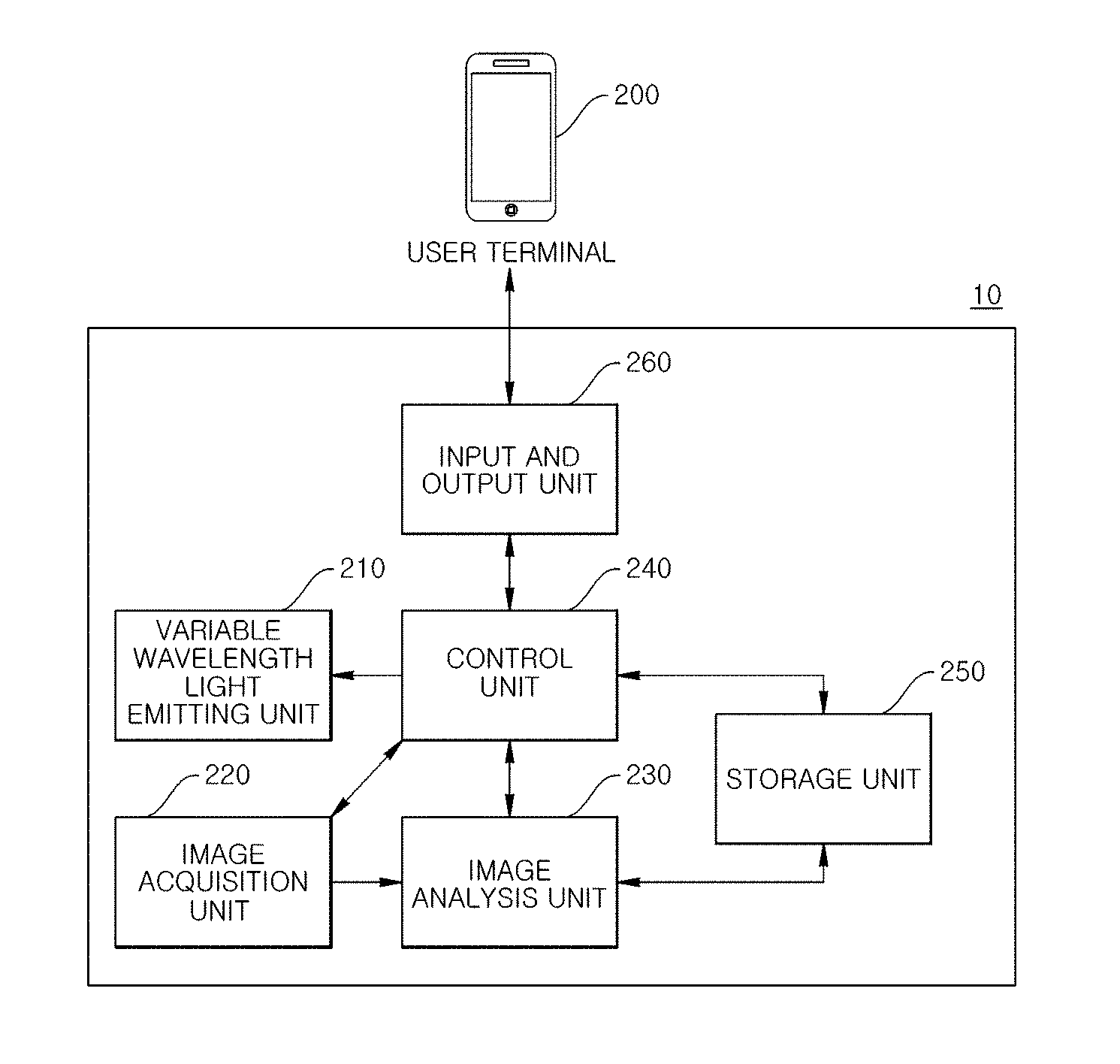
[0010] According to another aspect of the present disclosure, an image-based component measurement method using a light-emitting unit that outputs a variable wavelength includes selecting a component of a target object to be measured; checking a wavelength band corresponding to the selected component; adjusting a wavelength of the light emitting unit to a checked wavelength band; acquiring an image of the target object; processing and analyzing the acquired image; estimating content of the selected component according to an analysis result; and outputting component content results. In the adjusting of the wavelength of the light emitting unit, an irradiation region of a wavelength variable unit including a quantum dot for emitting light corresponding to a predetermined wavelength is adjusted such that light having a selected wavelength is output.
[0011] According to another aspect of the present disclosure, a plant cultivation method using an image-based component measurement system includes selecting a target component of a plant; checking a wavelength band corresponding to the selected component; adjusting a wavelength of a light emitting device having a variable wavelength to the checked wavelength band; acquiring an image of the plant; processing the acquired image; estimating content of the target component of the plant by analyzing the processed data; outputting component content results; determining whether or not the target component which is contained in the plant reaches a predetermined target value; adjusting a cultivation environment condition if the target component which is contained in the plant does not reach the predetermined target value; and reflecting component measurement results and the adjustment of the cultivation environment condition into a growth model of a relevant plant. In the adjusting of the wavelength of the light emitting device having the variable wavelength to the checked wavelength band, an irradiation region of a wavelength variable unit including a quantum dot for emitting light corresponding to a predetermined wavelength is adjusted such that light having a selected wavelength is output.
[0012] According to an image-based component measurement system and a method thereof using a light emitting unit that outputs a variable wavelength according to an embodiment of the present disclosure, it is possible to measure content of a component included in a target object by using a low-cost and small-sized device.
[0013] Meanwhile, if a configuration component of a plant (crop) is grasped by using a device which can perform a simple and low-cost component analysis through a component analysis measurement, a growth condition may be controlled by controlling a fertilizer component or by grasping a nutrition state, and since the plant is directly picked up without physical and chemical processing, time and cost are reduced and immediate feedback is possible.
[0014] That is, even if an accuracy is slightly lower than that of an expensive apparatus, there is an effect that it is possible to immediately know the content result and whether or not the component is contained.
[0015] In addition, according to the plant cultivation method using the light emitting unit that outputs the variable wavelength according to one embodiment of the present disclosure, it is possible to grasp the amount of content of the nutrients contained in the plant and to reflect into a growth model when the plant (crop) grows, and there is an effect that crops which are required for patient food, baby food, diet, and the like and have to contain satisfactory nutrients and the like in particular for diabetes, hypertension, cancer, and the like may be cultivated in a health-customized manner therethrough.
BRIEF DESCRIPTION OF THE DRAWINGS
[0016] FIGS. 1A and 1B are diagrams illustrating a quantum dot used in the present disclosure.
[0017] FIG. 2 is a configuration diagram of an example embodiment of an image-based component measurement system which uses a light emitting unit that outputs a variable wavelength according to the present disclosure.
[0018] FIG. 3 is an example graph illustrating a correlation between absorption values or reflection values of wavelengths which can be acquired from image information used in the present disclosure and a concentration (content) of actual components.
[0019] FIG. 4A is a configuration diagram illustrating an example embodiment of the light emitting unit of FIG. 2.
[0020] FIG. 4B is a diagram illustrating a first example embodiment of the light emitting unit that outputs the variable wavelength according to one embodiment used for the present disclosure.
[0021] FIG. 4C is a detailed configuration diagram of a wavelength variable unit 421 illustrated in FIG. 4B.
[0022] FIG. 5 is a diagram illustrating a second example embodiment of the light emitting unit that outputs the variable wavelength according to the embodiment used in the present disclosure.
[0023] FIG. 6 is a diagram illustrating a third example embodiment of the light emitting unit that outputs the variable wavelength according to the embodiment used in the present disclosure.
[0024] FIG. 7 is a configuration diagram illustrating another embodiment of the light emitting unit of FIG. 2.
[0025] FIG. 8 is a diagram illustrating a first example embodiment of a light emitting unit that outputs a variable wavelength according to another embodiment of the present disclosure.
[0026] FIG. 9 is a diagram illustrating a second example embodiment of the light emitting unit that outputs a variable wavelength according to another embodiment of the present disclosure.
[0027] FIG. 10 is a flowchart illustrating an example embodiment of an image-based component measurement method which uses the light emitting unit that outputs the variable wavelength according to the present disclosure.
[0028] FIG. 11 is a flowchart illustrating an example embodiment of a plant cultivation method which uses the image-based component measurement system according to the present disclosure.
DETAILED DESCRIPTION OF THE DISCLOSURE
[0029] The present disclosure is susceptible to various modifications and alternative forms, and specific embodiments thereof will be illustrated by way of examples in the drawings and will herein be described in detail.
[0030] It should be understood, however, that the present disclosure is not intended to be limited to the particular embodiments but includes all modifications, equivalents, and alternatives falling within the spirit and the scope of the present disclosure.
[0031] When an element is referred to as being "connected" or "coupled" to another element, the element may be directly connected or coupled to another element, but it is to be understood that other components may exist therebetween.
[0032] Meanwhile, when an element is referred to as being "directly connected" or "directly coupled" to another element, it is to be understood that other elements do not exist therebetween.
[0033] The terminology used herein is used for the purpose of describing a particular embodiment only and is not intended to limit the present disclosure.
[0034] The singular expression includes plural expressions unless the context clearly describes otherwise.
[0035] In the present application, it is to be understood that the term "include", "have" or the like is intended to specify existence of the feature, number, process, operation, configuration element, component or combination thereof described in the specification and does not exclude the existence or addition possibility of one or more other features, numbers, processes, operations, configuration elements, components, or combinations thereof.
[0036] Unless defined otherwise, all terms, which are used herein and include technical or scientific terms, have the same meaning as things commonly understood by those skilled in the art to which the present disclosure belongs.
[0037] Terms such as those defined in a commonly used dictionary are to be construed as having a meaning consistent with the meaning in the context of the relevant art and are not to be construed as ideal or overly formal in meaning unless explicitly defined in the present application.
[0038] Hereinafter, the present disclosure will be described in more detail with reference to the accompanying drawings.
[0039] Prior to this, terms and words used in the present specification and claims should not be construed as limited to ordinary or dictionary terms and should be construed in light of meaning and concepts consistent with the technical idea of the present disclosure, based on the principle that the inventor can properly define concept of the term in order to describe the disclosure in the best possible way.
[0040] In addition, unless otherwise defined, the technical terms and scientific terms used herein have the meanings as commonly understood by those skilled in the art to which the present disclosure belongs, and description on the known function and configuration that may unnecessarily blur the gist of the present disclosure in the following description and the accompanying drawings will be omitted.
[0041] The following drawings are provided by way of examples such that those skilled in the art can fully understand the spirit of the present disclosure.
[0042] Therefore, the present disclosure is not limited to the following drawings and may be embodied in other forms.
[0043] In addition, the same reference numerals designate the same configuration elements throughout the specification.
[0044] It is to be noted that the same configuration elements in the drawings are denoted by the same reference numerals wherever possible.
[0045] FIGS. 1A and 1B are diagrams illustrating a quantum dot used in the present disclosure.
[0046] The quantum dot is a semiconductor crystal in which a quantum is synthesized in nanometers (nm).
[0047] When ultraviolet rays (blue light) are applied to the quantum dot, even particles of the same component exhibit various colors depending on sizes of the particles, and such characteristics are better represented by a semiconductor material than a general material.
[0048] Elements such as cadmium, cadmium sulfide, cadmium selenide, and indium phosphide, which have such characteristics, are utilized for the quantum dot semiconductor crystal.
[0049] Recently, a zinc-selenium-sulfur alloy (ZnSeS) is wrapped around the indium phosphide core to eliminate the heavy metal cadmium.
[0050] As illustrated in FIG. 1A, if the quantum dot is small, the quantum dot emits a visible light having a short wavelength such as green, and as the size increases, the quantum dot emits the visible light having a long wavelength such as red.
[0051] In general, bandgap energy, owing to a quantum confinement effect, is controlled according to the size of the quantum dot, and thereby, energy of various wavelengths is emitted.
[0052] That is, as an energy level of an electron is lowered in the quantum dot, the quantum dot emits light, and the larger the quantum dot is, the narrower the space between the energy levels is, and thereby, a red color of a longer wavelength having a relatively low energy is emitted.
[0053] (Source of FIG. 1A: http://informationdisplay.org)
[0054] Referring to FIG. 1B, a principle of the quantum dot is that, if quanta, that is, electrons in a semiconductor material receive energy of ultraviolet rays or the like, the electrons go up to a higher energy level by performing a quantum jump, emit energy, and go down to a lower energy level. Thereby, energy of various wavelengths is emitted depending on a size of the quantum dot.
[0055] If a region of the wavelength (energy) is a visible region (380 nm to 800 nm), it is a principle that various visible colors are emitted as wavelengths of energy forms.
[0056] That is, if the quantum dot absorbs light from an excitation source and reaches an energy-excited state, the quantum dot emits energy corresponding to an energy band gap of the quantum dot.
[0057] Therefore, by controlling the size or material composition of the quantum dot, it is possible to control the energy band gap, and thereby, light can be emitted in the entire regions from an ultraviolet region to an infrared region.
[0058] The quantum dot may be produced by a vapor deposition method such as a metal organic chemical vapor deposition (MOCVD) method or a molecular beam epitaxy (MBE) method, or may be produced by a chemical wet synthesis method.
[0059] Since the quantum dots produced by the chemical wet synthesis method are dispersed in a solvent in a colloidal state, the quantum dots are separated from the solvent through centrifugation, and the separated quantum dots can be dispersed in a produced metal-organic precursor solution.
[0060] At this time, the quantum dots can be stabilized by bonding with an organic matter of the metal-organic precursor.
[0061] FIG. 2 is a configuration diagram illustrating an example embodiment of an image-based component measurement system 10 using a light emitting unit that outputs a variable wavelength according to the present disclosure.
[0062] As illustrated in FIG. 2, the image-based component measurement system using the light emitting unit that outputs the variable wavelength according to the present disclosure includes a variable wavelength light emitting unit 210, an image acquisition unit 220, an image analysis unit 230, a control unit 240, a storage unit 250, and an input and output unit 260.
[0063] The variable wavelength light emitting unit 210 outputs light having a wavelength necessary for analyzing components of a target object.
[0064] The image acquisition unit 220 acquires image information of the target object.
[0065] For example, the image acquisition unit 220 includes an image capturing device such as a camera.
[0066] The image analysis unit 230 processes an image acquired by the image acquisition unit 220 to analyze an absorption wavelength and a reflection wavelength of the target object.
[0067] The control unit 240 controls each of the variable wavelength light emitting unit 210, the image acquisition unit 220, and the image analysis unit 230, outputs light having a wavelength corresponding to a component to be detected of the target object through the variable wavelength light emitting unit 210, controls image acquisition timing of the target object in the image acquisition unit 220, and receives data in which the image information of the target object is analyzed from the image analysis unit 230 to determine existence and content of the component which is included in the target object and is intended to be analyzed.
[0068] The storage unit 250 stores data required by the variable wavelength light emitting unit 210, the image analysis unit 230, and the control unit 240.
[0069] That is, the storage unit 250 stores data necessary for the image-based component measurement system 10.
[0070] Meanwhile, FIG. 2 illustrates that the data is stored in the storage unit 250 included in the image-based component measurement system 10, but the storage unit may also be implemented in a database system or cloud which is provided separately via wired or wireless communication.
[0071] The input and output unit 260 receives a component to be analyzed with respect to the target object from a user and outputs an analysis result of the input component to the user.
[0072] FIG. 2 illustrates that the data is input and output via a separately provided user terminal 200, but it is also possible for the data to be input and output via input and output means provided in the image-based component measurement system 10.
[0073] If the target object is irradiated with light having a wavelength changed according to a component to be analyzed from the variable wavelength light emitting unit 210 under the control of the control unit 240, the image analysis unit 230 can measure a reflection value, a fluorescence value, and the like from the image information (image) transmitted from the image acquisition unit 220 and grasp the component included in the target object.
[0074] In a case of a plant, existence and content of nutrients N, P, K, Ca, Mg, Fe, Zn, and the like for the plant growth can be grasped and specific quality components included in the plant, which are anthocyanin, ascorbic acid, carotenoid, lutein, and the like, can be grasped and utilized for a growth control.
[0075] For example, it is possible to measure the content of the anthocyanin by applying light having wavelengths of 550 nm and 700 nm and measuring reflection values.
[0076] In addition, it is possible to measure contents of N, P, K, Ca, Mg, Fe, Mn, Zn, and Cu by measuring reflection values of light having wavelengths of 400 to 1100 nm. FIG. 3 is a graph illustrating a correlation between absorption values or reflection values of wavelengths acquired from the image information used in the present disclosure and a concentration (content) of actual components.
[0077] In FIG. 3, the absorption value or the reflection value of a specific wavelength acquired from the image information of the plant is illustrated on the y-axis, and component information acquired by processing the plant and extracting the anthocyanin component is illustrated on the x-axis.
[0078] The closer the R value is to 1, the stronger the correlation is, and the graph illustrates that the R value is as high as 0.9455.
[0079] Through the above-described experiment, a correlation equation between the absorption value or the reflection value of the wavelength acquired from the image information and the content of the actual component can be derived, and the storage unit 250 stores the correlation equation and the data stored in a history, and a configuration component can be measured from absorption values and reflection values of the specific wavelength acquired through image processing under the control of the control unit 240.
[0080] FIG. 4A is a configuration diagram illustrating an example embodiment of the variable wavelength light emitting unit of FIG. 2 according to the present disclosure.
[0081] As illustrated in FIG. 4A, the variable wavelength light emitting unit includes a light source 410, a wavelength variable unit 420, and a drive unit 430.
[0082] The light source 410 includes at least one light emitting source, and, for example, a plurality of light emitting sources may be arranged in a matrix form.
[0083] The light emitting source includes an LED emitting white or blue light.
[0084] The wavelength variable unit 420 is spaced apart from the light source 410 by a predetermined distance and includes quantum dots that emit light corresponding to a predetermined wavelength in each of a plurality of separated regions with respect to each of the light emitting sources or corresponding to each column or each row of the light emitting sources.
[0085] The drive unit 430 controls a location of the light emitting source or the wavelength variable unit 420 so as to change an irradiation region of the wavelength variable unit 420 by the light emitting source.
[0086] The control unit 240 controls an operation of each of the drive units 430 to adjust the wavelength output from the variable wavelength light emitting unit.
[0087] Specifically, the control unit 240 changes a location of the wavelength variable unit 420 or the light source 410 according to the wavelength for analyzing the selected components with reference to the information on the wavelengths necessary for analyzing the components of the target object and a mixture ratio of the wavelengths and output wavelength information according to the location control of the wavelength variable unit 420 or the light source 410. Thus, the control unit 240 is able to adjust the wavelengths output from the variable wavelength light emitting unit.
[0088] That is, the variable wavelength light emitting unit emits light having a wavelength corresponding to the component to be analyzed under the control of the control unit 240.
[0089] The variable wavelength light emitting unit further includes an interval adjustment unit 440.
[0090] The interval adjustment unit 440 adjusts a distance between the light source 410 and the wavelength variable unit 420 according to the control of the control unit 240.
[0091] Hereinafter, an embodiment of the variable wavelength light emitting unit used in the present disclosure will be described with reference to FIGS. 4B, 4C, 5, and 6.
[0092] FIG. 4B is a diagram illustrating a first embodiment of a light emitting unit that outputs a variable wavelength according to one embodiment used for the present disclosure, and FIG. 4C is a detailed configuration diagram of the wavelength variable unit 421 illustrated in FIG. 4B.
[0093] As illustrated in FIG. 4B, the wavelength variable unit 421 includes a first region 422 for allowing a wavelength of the light emitting source 411 to be output as it is, a second region 423 including a quantum dot for emitting red, a third region 424 in which a quantum dot for emitting red and a quantum dot for emitting green are stacked, and a fourth region 425 in which a quantum dot for emitting the red, a quantum dot for emitting violet, a quantum dot for emitting the green, and a quantum dot for emitting yellow are stacked.
[0094] Meanwhile, only the region including the quantum dot for emitting the red is illustrated in the figure, but a region including the quantum dot for emitting the green and a region (not illustrated) including the quantum dot for emitting blue can be illustrated.
[0095] Meanwhile, the wavelength variable unit 421 may include a region (not illustrated) including a quantum dot in which two or more quantum dots of red, green, and blue quantum dots are mixed to emit a new random color (for example, yellow, violet, or the like).
[0096] Meanwhile, in the fourth region 425 in which a plurality of layers formed with the quantum dots are formed, the quantum dots that absorb and emit long wavelengths may be stacked so as to be adjacent to the light emitting source 411, and in the region 425, the quantum dots that absorb and emit the long wavelengths may be stacked so as to be located far from the light emitting source 411.
[0097] The wavelength variable unit 421 may further include an optical film 426 for protecting the plurality of separated regions 422 to 425 and a color filter 427 for increasing a color purity of light passing through the plurality of separated regions 422 to 425.
[0098] The drive unit 430 may adjust locations of the wavelength variable unit 420 or the light source 410 in the x and y directions such that an irradiation region of the wavelength variable unit 420 is changed by the light emitting source, and an interval adjustment unit (not illustrated) which adjusts an interval between the light emitting source 411 and the wavelength variable unit 421 adjust a location in the z direction.
[0099] As illustrated in FIG. 4C, a first embodiment of the light emitting unit that outputs a variable wavelength according to one embodiment used for the present disclosure includes the light source 410, the wavelength variable unit 420, the drive unit 430, and a control unit 240.
[0100] The light source 410 includes at least one light emitting source 411, and for example, a plurality of light emitting sources are arranged in the form of a matrix 7.times.7.
[0101] The wavelength variable unit 420 is spaced apart from the light source 410 by a predetermined distance and is illustrated as four hexagons corresponding to each light emitting source 411, and each hexagonal region includes a quantum dot for emitting light corresponding to a predetermined wavelength.
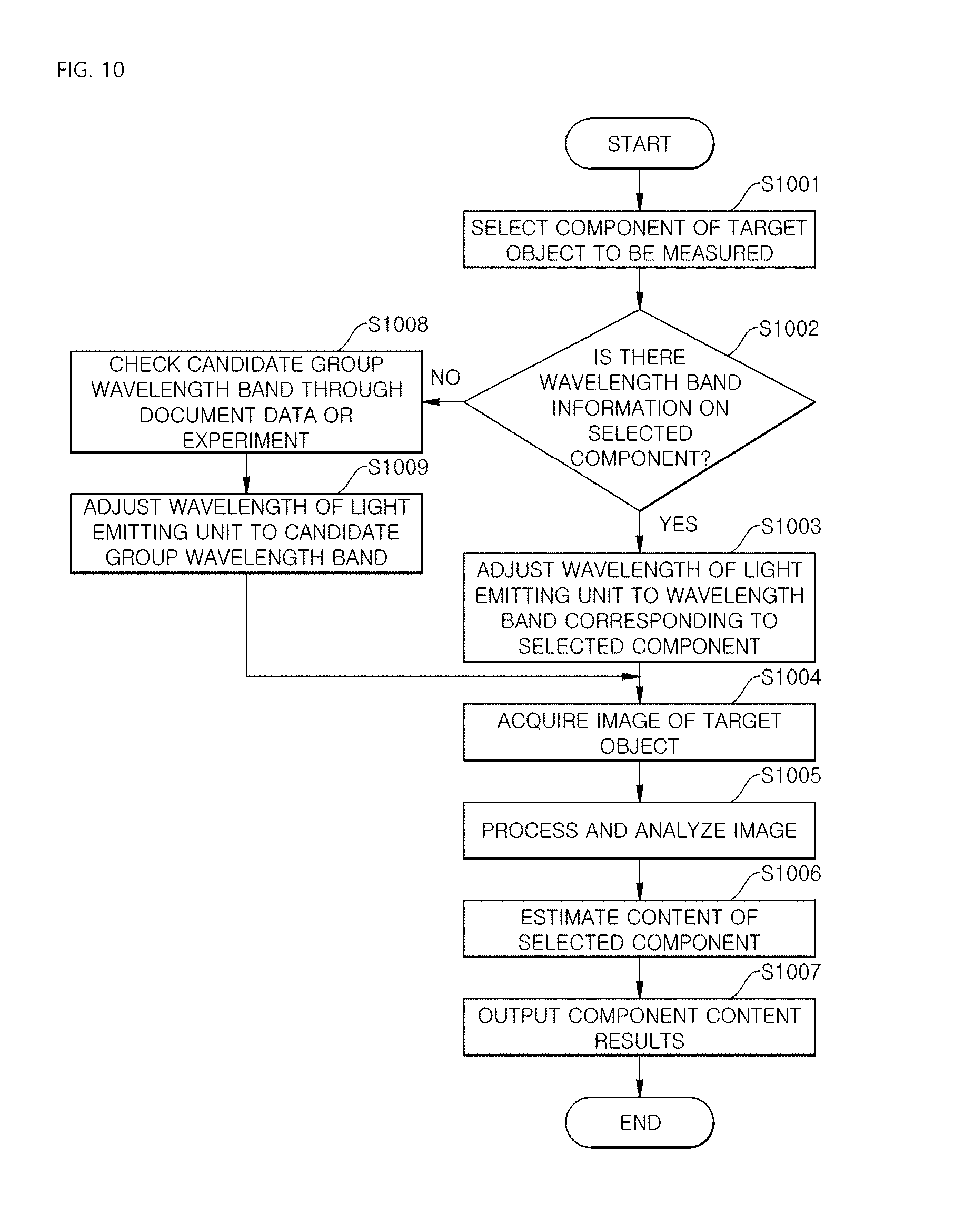
[0102] The drive unit 430 controls the location of the wavelength variable unit 420 in the x and y directions on a row-by-row basis such an irradiation region of the wavelength variable unit 420 is changed by the light emitting source, and at least one of the drive unit can be provided.
[0103] The control unit 240 controls an operation of each of the drive units 430 to adjust the wavelength output from the variable wavelength light emitting unit.
[0104] FIG. 4C illustrates that the drive unit 430 controls the wavelength variable unit 420 on a row-by-row basis to change the irradiation region, but it is possible to control the wavelength variable unit 420 on a column-by-column basis and it is also possible to control the location of the light sources 410 on a row-by-row basis or column-by-column basis to change the irradiation region.
[0105] FIG. 5 is a diagram illustrating a second embodiment of the light emitting unit that outputs the variable wavelength according to the embodiment of the present disclosure.
[0106] As illustrated in FIG. 5, the second embodiment of the light emitting unit that outputs the variable wavelength includes a light source 510, a wavelength variable unit 520, and a drive unit 530.
[0107] The light source 510 includes at least one light emitting source 511, and for example, a plurality of light emitting sources are arranged in the form of a matrix 7.times.7.
[0108] The wavelength variable unit 520 is spaced apart from the light source 510 by a predetermined distance and is illustrated in a four-line form corresponding to each row unit of the light emitting source 511, and each line region includes a quantum dot for emitting light corresponding to a predetermined wavelength.
[0109] The drive unit 530 controls a location of the wavelength variable unit 520 in the diagonal direction on a row-by-row basis to change an irradiation region of the wavelength variable unit 520 by the light source 510, and at least one of the drive units can be provided.
[0110] The control unit 240 controls an operation of each of the drive units 530 to adjust the wavelengths output from the variable wavelength light emitting unit.
[0111] FIG. 5 illustrates that the drive unit 530 controls the wavelength variable unit 520 on a row-by-row basis to change the irradiation regions, but it is also possible to control the wavelength variable unit 520 on a column-by-column basis and it is also possible for the drive unit 530 to control the location of the light source 510 on a row-by-row basis or a column-by-column basis to change the irradiation regions.
[0112] FIG. 6 is a diagram illustrating a third embodiment of the light emitting unit that outputs the variable wavelength according to the embodiment of the present disclosure.
[0113] As illustrated in FIG. 6, the third embodiment of the light emitting unit that outputs the variable wavelength includes a light source 610, a wavelength variable unit 620, and a drive unit 630.
[0114] The light source 610 includes at least one light emitting source 611. For example, a plurality of light emitting sources are arranged in the form of a matrix 7.times.7.
[0115] The wavelength variable unit 620 is spaced apart from the light source 610 by a predetermined distance and is illustrated as an octagon divided into eight regions corresponding to the respective light emitting sources 611 respectively, and each region has a quantum dot that emits light corresponding to a predetermined wavelength.
[0116] Here, a shape of each light emitting source 611 may be circular.
[0117] That is, each wavelength variable unit 620 corresponding to the respective light emitting sources 611 has eight triangular shapes with respect to a central point, and each region has a quantum dot for emitting light corresponding to the predetermined wavelength.
[0118] The drive unit 630 rotates the wavelength variable unit 620 to change an irradiation region of the wavelength variable unit 620 by the light emitting source 611, and the same number of drive units 620 as the wavelength variable units 620 are provided.
[0119] The control unit 240 controls an operation of each of the drive units 630 to adjust the wavelengths output from a plant growth light emitting device having a variable wavelength for which the quantum dots are used.
[0120] FIG. 6 illustrates that the drive unit 630 changes the irradiation region by rotating the wavelength variable unit 620, but it is also possible for the drive unit 630 to control the location of the light emitting source 611 to change the irradiation region.
[0121] For example, the drive unit 630 may be configured to rotate through attraction and repulsion by using an electromagnet having a polarity changing according to a current and can be designed such that the wavelength variable unit 620 or the light emitting source 611 can be rotationally moved through the rotating drive unit 630.
[0122] A method of changing the irradiation region by rotating the wavelength variable unit 620 by means of the drive unit 630 rotating under the control of the control unit 240 may be understood by referring to the configuration diagram of a portion 600 of the variable wavelength light emitting unit.
[0123] Meanwhile, the rotating drive unit 630 may be designed to move a rotation member in the z-axis direction.
[0124] Therefore, the rotating drive unit 630 may be used as an interval adjustment unit that can adjust an interval between the light emitting source 611 and the wavelength variable unit 620.
[0125] FIG. 7 is a configuration diagram illustrating another embodiment of the light emitting unit illustrated in FIG. 2.
[0126] As illustrated in FIG. 7, the light emitting unit that outputs a variable wavelength includes a light source 710 and a wavelength variable unit 720.
[0127] The light source 710 may include at least one light emitting source, and a plurality of light emitting sources may be arranged in the form of a matrix.
[0128] The wavelength variable unit 720 is spaced apart from the light source 710 by a predetermined distance and includes quantum dots that emit light corresponding to a predetermined wavelength in each of a plurality of the separated regions with respect to each of the light emitting sources or corresponding to columns or rows of the light emitting sources.
[0129] The control unit 240 controls an operation of the light source 710 to adjust wavelengths output from the plant growth light emitting device having a variable wavelength for which the quantum dots are used.
[0130] Specifically, the control unit 240 controls ON, OFF or activation time (turn-on time) of each light emitting source of the light source 710 according to the wavelength for analyzing the selected component with reference to information on a wavelength necessary for analyzing the component of a target object and a mixture ratio of the wavelength and output wavelength information according to a location of the light source 710, thereby, controlling the wavelength output from the variable wavelength light emitting unit.
[0131] Meanwhile, intensity of the corresponding wavelength may also be controlled by adjusting the light intensity (intensity) of each light emitting source.
[0132] ON or OFF of the light emitting source may be adjusted by a pulse width modulation (PWM) signal for controlling the light emitting source, and the light intensity of the light emitting source may be controlled by, for example, a dimmer which is a light adjustment device.
[0133] That is, the variable wavelength light emitting unit outputs light having a wavelength corresponding to a component to be analyzed.
[0134] The light emitting unit that outputs a variable wavelength further includes an interval adjustment unit 730.
[0135] The interval adjustment unit 730 adjusts a distance between the light source 710 and the wavelength variable unit 720 under the control of the control unit 240.
[0136] Hereinafter, an embodiment of the light emitting unit that outputs a variable wavelength according to another embodiment of the present disclosure will be described with reference to FIGS. 8 and 9.
[0137] FIG. 8 is a diagram illustrating a first embodiment of the light emitting unit that outputs the variable wavelength according to another embodiment of the present disclosure. As illustrated in FIG. 8, the first embodiment of the light emitting unit that outputs the variable wavelength includes a light source 810 and a wavelength variable unit 820.
[0138] The light source 810 includes at least one light emitting source 811, and, for example, a plurality of light emitting sources are arranged in the form of a matrix 7.times.7.
[0139] The wavelength variable unit 820 is spaced apart from the light source 810 by a predetermined distance and is illustrated as a region including at least one hexagon corresponding to each of the light emitting sources 811, and each hexagonal region includes a quantum dot for emitting light corresponding to a predetermined wavelength.
[0140] Meanwhile, the quantum dot region may have another shape such as a triangle, a square, and a circle as well as the hexagon.
[0141] Specifically, each light emitting source 811 may correspond to a region including quantum dots for emitting colors having different wavelengths and may correspond to a region in which quantum dots for emitting at least two or more different colors are combined.
[0142] The wavelength variable unit 820 may further include an optical film (not illustrated) for protecting a plurality of separated regions and a color filter (not illustrated) for increasing color purity of light passing through the plurality of separated regions.
[0143] The control unit 240 controls an operation of each of the light emitting sources 811 to adjust a wavelength output from the variable wavelength light emitting unit.
[0144] Specifically, the control unit 240 controls ON, OFF or activation time (turn-on time) of each light emitting source of the light source 810 according to the wavelength for analyzing the selected component with reference to information on a wavelength necessary for analyzing the component of a target object and a mixture ratio of the wavelength and output wavelength information according to a location of each light emitting source of the light source 810, thereby, controlling the wavelength output from a light emitting device.
[0145] Meanwhile, intensity of the corresponding wavelength may also be controlled by adjusting the light intensity (intensity) of each light emitting source.
[0146] FIG. 9 is a diagram illustrating a second embodiment of a light emitting unit that outputs a variable wavelength according to another embodiment of the present disclosure.
[0147] As illustrated in FIG. 9, the second embodiment of the light emitting unit that outputs the variable wavelength includes a light source 910 and a wavelength variable unit 920.
[0148] The light source 910 includes at least one light emitting source 911, and, for example, a plurality of light emitting sources are arranged in the form of a matrix 7.times.7.
[0149] The wavelength variable unit 920 is spaced apart from the light source 910 by a predetermined distance and is illustrated as a region including at least one line shape corresponding to a light emitting source 911 on a row-by-row basis, and each region of the line shape includes a quantum dot for emitting light corresponding to a predetermined wavelength.
[0150] Specifically, the light emitting sources 911 on a row-by-row basis may correspond to a region including quantum dots for emitting colors having different wavelengths and may correspond to a region in which quantum dots for emitting at least two or more different colors are combined.
[0151] The wavelength variable unit 920 may further include an optical film (not illustrated) for protecting a plurality of separated regions and a color filter (not illustrated) for increasing color purity of light passing through the plurality of separated regions. The control unit 240 controls the light emitting sources 911 on the row-by-row basis or operations of the respective light emitting sources 911 to adjust the wavelength output from the variable wavelength light emitting unit.
[0152] Specifically, the control unit 240 controls ON, OFF or activation time (turn-on time) of each light emitting source of the light source 910 according to the wavelength for analyzing the selected component with reference to information on a wavelength necessary for analyzing the component of a target object and a mixture ratio of the wavelength and output wavelength information according to a location of each light emitting source of the light source 910, thereby, controlling the wavelength output from a light emitting device.
[0153] Meanwhile, intensity of the corresponding wavelength may also be controlled by adjusting the light intensity (intensity) of each light emitting source.
[0154] FIG. 9 illustrates that the wavelength is changed by controlling an operation of the light emitting source 911 on a row-to-row basis or controlling each, but it is also possible to control the operation of the light emitting source 911 on a column-by-column basis.
[0155] FIG. 10 is a flowchart illustrating an example embodiment of an image-based component measurement method which uses a light emitting unit that outputs a variable wavelength according to the present disclosure.
[0156] First, a component of a target object to be measured is selected (S1001).
[0157] Thereafter, whether or not there is wavelength band information on the selected component is determined (S1002).
[0158] If it is determined in step S1002 that there is the wavelength band information on the selected component, the wavelength of the light emitting unit is adjusted to a wavelength band corresponding to the selected component (S1003).
[0159] Thereafter, an image of a target object is acquired (S1004).
[0160] In step S1004 of acquiring the image of the target object, the image of the target object is acquired in a state in which there is light having a wavelength necessary for analyzing a component to be measured, or the image of the target object is acquired in a state in which light disappears after the light is emitted from the variable wavelength light emitting unit 210.
[0161] Thereafter, image processing and analysis for the acquired image are performed (S1005).
[0162] At this time, only the reflected light to be measured remains and noise is removed through a preprocessing process of each image for each wavelength, and thereby, a reflectance of each measurement point for each wavelength is acquired.
[0163] Thereafter, content of the selected component is estimated from a correlation equation between a reflectance value for each measurement point for each wavelength and the reflectance and component stored in a database (S1006).
[0164] Thereafter, a result of the component content is output (S1007).
[0165] Meanwhile, if it is determined in step S1002 that there is no wavelength band information on the selected component, a candidate group wavelength band is checked through document data or an experiment (S1008).
[0166] A method of checking the candidate group wavelength band through the experiment includes a method of measuring images of various wavelengths and comparing the measurement result with a direct component analysis result such as an extraction method.
[0167] For example, a data processing technique such as a partial least squares discriminant analysis (PLS-DA) is used.
[0168] By using this method, the candidate group wavelength band information on each component is acquired and stored.
[0169] The wavelength of the light emitting unit is adjusted to the candidate group wavelength band (S1009), the processing proceeds to step S1004, and next step is performed.
[0170] FIG. 11 is a flowchart illustrating an example embodiment of a plant cultivation method which uses an image-based component measurement system according to the present disclosure.
[0171] First, a target component of a plant to be measured is selected (S1101).
[0172] Thereafter, whether or not there is wavelength band information on the selected component is determined (S1102).
[0173] If it is determined in step S1102 that there is the wavelength band information on the selected target component, the wavelength of the light emitting unit is adjusted to a wavelength band corresponding to the selected component (S1103).
[0174] Thereafter, an image of the plant is acquired (S1104).
[0175] In step S1104 of acquiring an image of the plant, the image of the plant is acquired in a state in which there is light having a wavelength necessary for analyzing a component to be measured, or the image of the plant is acquired in a state in which light disappears after the light is emitted from the variable wavelength light emitting unit 210.
[0176] Thereafter, image processing and analysis for the acquired image are performed (S1105).
[0177] At this time, the reflected light to be measured remains and noise is removed through a preprocessing process of each image for each wavelength, and thereby, a reflectance of each measurement point for each wavelength is acquired.
[0178] Thereafter, content of the selected component is estimated from a correlation equation between a reflectance value for each measurement point for each wavelength and the reflectance and component stored in a database (S1106).
[0179] Thereafter, a result of the component content is output (S1107).
[0180] Thereafter, whether or not the content of the selected target component reaches a predetermined target value is determined (S1108).
[0181] If the component contained in the plant reaches the predetermined target value, harvest or cultivation is continued (S1109).
[0182] Meanwhile, if the component contained in the plant does not reach the predetermined target value, a cultivation environment condition is adjusted (S1110).
[0183] Thereafter, the component measurement result and the adjustment of the cultivation environment condition are reflected in a growth model of a relevant plant (S1111).
[0184] Meanwhile, if it is determined in step S1102 that there is no wavelength band information on the selected target component, a candidate group wavelength band is checked through document data or an experiment (S1112).
[0185] A method of checking the candidate group wavelength band through the experiment includes a method of measuring images of various wavelengths and comparing the measurement result with a direct component analysis result such as an extraction method.
[0186] For example, a data processing technique such as a partial least squares discriminant analysis (PLS-DA) is used.
[0187] By using the method, the candidate group wavelength band information on each component is acquired and stored.
[0188] The wavelength of the light emitting unit is adjusted to the candidate group wavelength band (S1113), the processing proceeds to step S1104, and next step is performed.
[0189] Although a plant cultivation method of using an image-based component measurement method and an image-based component measurement system which use a light emitting unit that outputs a variable wavelength according to an embodiment of the present disclosure is described, it is also possible to realize a computer-readable recording medium storing a program for implementing the plant cultivation method of using the image-based component measurement method and the image-based component measurement system which use the light emitting unit that outputs the variable wavelength, and a program stored in the computer-readable recording medium storing the program for implementing the plant cultivation method of using the image-based component measurement method and the image-based component measurement system which use the light emitting unit that outputs the variable wavelength.
[0190] That is, it will be readily apparent to those skilled in the art that the plant cultivation method of using the image-based component measurement method and the image-based component measurement system which use the light emitting unit that outputs the variable wavelength may be provided in a state of being included in a recording medium which can be read by a computer by tangibly embodying a program of commands for implementing the plant cultivation method.
[0191] In other words, the plant cultivation method may be implemented in the form of a program command that can be executed through various computer means so as to be recorded in a computer-readable recording medium.
[0192] The computer-readable recording medium may include a program command, a data file, a data structure, and the like, alone or in combination.
[0193] The program commands recorded in the computer-readable recording medium may be specifically designed and configured for the present disclosure or may be known and available to those skilled in the computer software.
[0194] An example of the computer-readable medium includes a magnetic medium such as a hard disk, a floppy disk, and a magnetic tape, an optical medium such as a CD-ROM and a DVD, a magneto-optical medium such as a floptical disk, and a hardware device specifically configured to store and execute a program command such as a ROM, a RAM, a flash memory, and a USB memory.
[0195] The computer-readable recording medium may be a transmission medium such as light, a metal line or a wave guide including a carrier wave for transmitting a signal that designates a program command, a data structure, and the like.
[0196] An example of the program command includes not only a machine language code generated by a compiler, but also a high-level language code that can be executed by a computer using an interpreter or the like.
[0197] The hardware device may be configured to operate as one or more software modules to perform operations of the present disclosure and vice versa.
[0198] The present disclosure is not limited to the above-described embodiments, and it goes without saying that the scope of application of the present disclosure is various and that the present disclosure may be embodied in various forms without departing from the spirit and scope of the disclosure as defined in the appended claims.
* * * * *
References
D00000
D00001
D00002
D00003
D00004
D00005
D00006
D00007
D00008
D00009
D00010
XML
uspto.report is an independent third-party trademark research tool that is not affiliated, endorsed, or sponsored by the United States Patent and Trademark Office (USPTO) or any other governmental organization. The information provided by uspto.report is based on publicly available data at the time of writing and is intended for informational purposes only.
While we strive to provide accurate and up-to-date information, we do not guarantee the accuracy, completeness, reliability, or suitability of the information displayed on this site. The use of this site is at your own risk. Any reliance you place on such information is therefore strictly at your own risk.
All official trademark data, including owner information, should be verified by visiting the official USPTO website at www.uspto.gov. This site is not intended to replace professional legal advice and should not be used as a substitute for consulting with a legal professional who is knowledgeable about trademark law.