Safety Control Unit, Safety Control Method, And Safety Control Program
KOJIMA; Tatsuya ; et al.
U.S. patent application number 16/325422 was filed with the patent office on 2019-07-11 for safety control unit, safety control method, and safety control program. This patent application is currently assigned to OMRON Corporation. The applicant listed for this patent is OMRON Corporation. Invention is credited to Tatsuya KOJIMA, Katsushige OHNUKI, Takamasa UEDA, Koji YAOITA.
| Application Number | 20190212708 16/325422 |
| Document ID | / |
| Family ID | 61760458 |
| Filed Date | 2019-07-11 |

| United States Patent Application | 20190212708 |
| Kind Code | A1 |
| KOJIMA; Tatsuya ; et al. | July 11, 2019 |
SAFETY CONTROL UNIT, SAFETY CONTROL METHOD, AND SAFETY CONTROL PROGRAM
Abstract
A safety control unit includes: a memory; a computation control part; and an input and output unit for connecting the computation control part to a safety input device and an output device to be safely controlled. A system program includes a data refresh program for executing a data refresh of safety control data of the safety input device and the output device and the control data of the memory via the input and output unit. If the computation control part receives a change of a control program, the computation control part stops executing the control program. The computation control part executes the change of the control program while executing a part of the system program including the data refresh. The computation control part resumes executing the control program.
| Inventors: | KOJIMA; Tatsuya; (Kyoto-shi, JP) ; YAOITA; Koji; (Kyoto-shi, JP) ; UEDA; Takamasa; (Kyoto-shi, JP) ; OHNUKI; Katsushige; (Kyoto-shi, JP) | ||||||||||
| Applicant: |
|
||||||||||
|---|---|---|---|---|---|---|---|---|---|---|---|
| Assignee: | OMRON Corporation Kyoto-shi, KYOTO JP |
||||||||||
| Family ID: | 61760458 | ||||||||||
| Appl. No.: | 16/325422 | ||||||||||
| Filed: | August 23, 2017 | ||||||||||
| PCT Filed: | August 23, 2017 | ||||||||||
| PCT NO: | PCT/JP2017/030049 | ||||||||||
| 371 Date: | February 14, 2019 |
| Current U.S. Class: | 1/1 |
| Current CPC Class: | G05B 19/418 20130101; G05B 2219/13153 20130101; G05B 19/056 20130101; G05B 2219/14006 20130101; G05B 19/05 20130101; G05B 2219/14007 20130101; G05B 9/02 20130101 |
| International Class: | G05B 9/02 20060101 G05B009/02; G05B 19/418 20060101 G05B019/418 |
Foreign Application Data
| Date | Code | Application Number |
|---|---|---|
| Sep 30, 2016 | JP | 2016-194883 |
Claims
1. A safety control unit comprising: a memory that stores a system program for safety control, a control program for safety control, and control data; a computation control part configured to execute safety control using the control data, the system program, and the control program; and an input and output unit connecting the computation control part to a safety input device and an output device to be safely controlled, wherein the system program comprises a data refresh of control data of the safety input device and the output device and the memory via the input and output unit, and the computation control part is configured to perform operations comprising: stopping executing the control program, if the computation control part receives a change of the control program, executing the change of the control program while executing a part of the system program comprising the data refresh program, and resuming executing the control program.
2. The safety control unit according to claim 1, wherein the computation control part is further configured with the program such that the computation control part executes, in response to the computation control part receiving an instruction to change the control program while continuing the safety control, the change of the control program while executing the part of the system program comprising the data refresh program.
3. A safety control method, comprising: executing safety control using control data, a system program, and a control program; receiving a change of the control program; stopping executing the control program upon receiving the change of the control program; executing the change of the control program while executing a part of the system program comprising a data refresh program of the control data that is used for the safety control; and resuming executing the control program.
4. A non-transitory computer-readable recording medium storing a safety control program, which when read and executed, for causing a computation control part to execute operations comprising: executing safety control using control data, a system program, and a control program; receiving a change of the control program; stopping executing the control program upon receiving the change of the control program; executing the change of the control program while executing a part of the system program comprising a data refresh program of the control data that is used for the safety control; and resuming executing the control program.
Description
TECHNICAL FIELD
[0001] The present invention relates to a safety control unit for FA systems, and a safety control technique in FA systems.
BACKGROUND ART
[0002] Currently, many FA (Factory Automation) systems are used.
[0003] As described in Patent Document 1, external devices of an FA system are controlled by a control unit (programmable logic controller). With such a configuration of the FA system, a safety control system that uses a safety device as an external device can also be constituted.
[0004] In such a safety control system, a control unit (safety control unit) performs batch conversion (data refresh) of control data including data for safety control, with respect to any external devices including the safety device. Specifically, after the control unit executes a series of programs for controlling the FA system, the control unit performs a data refresh and again executes the series of programs. The data for safety control is updated at the time of this data refresh. Then, the safety control in the safety control system is realized by repeating this process.
RELATED ART DOCUMENT
Patent Document
[0005] Patent Document 1: JP 2009-9505A
SUMMARY OF THE INVENTION
[0006] However, if conventional safety control units are subject to a program change from the outside, the conventional safety control units temporarily stop all programs including any data refresh. For this reason, the safety control unit can not input safety control data, and stops the external devices included in the FA system. That is, the safety control of the FA system stops.
[0007] Accordingly, the present invention aims to provide a safety control unit and a safety control technique that can prevent an unnecessary stop due to safety control, for example, at a time when a program is changed.
Means for Solving the Problems
[0008] A safety control unit according to the present invention includes: a memory that stores a system program for safety control, a control program for safety control, and a control data; a computation control part configured to execute safety control using the control data, the system program, and the control program; and an input and output unit for connecting the computation control part to a safety input device and an output device to be safely controlled. The system program includes a data refresh of the control data of the safety input device and the output device and the memory via the input and output unit. If the computation control part receives a change of the control program, the computation control part stops executing the control program. The computation control part executes the change of the control program while executing a part of the system program including the data refresh. The computation control part resumes the execution the control program.
[0009] In this configuration, because the data refresh is continued when the control program is changed, the safety control is continued.
Effects of the Invention
[0010] According to the present invention, an unnecessary stop of the safety control can be prevented, for example, at a time when a program is changed.
BRIEF DESCRIPTION OF THE DRAWINGS
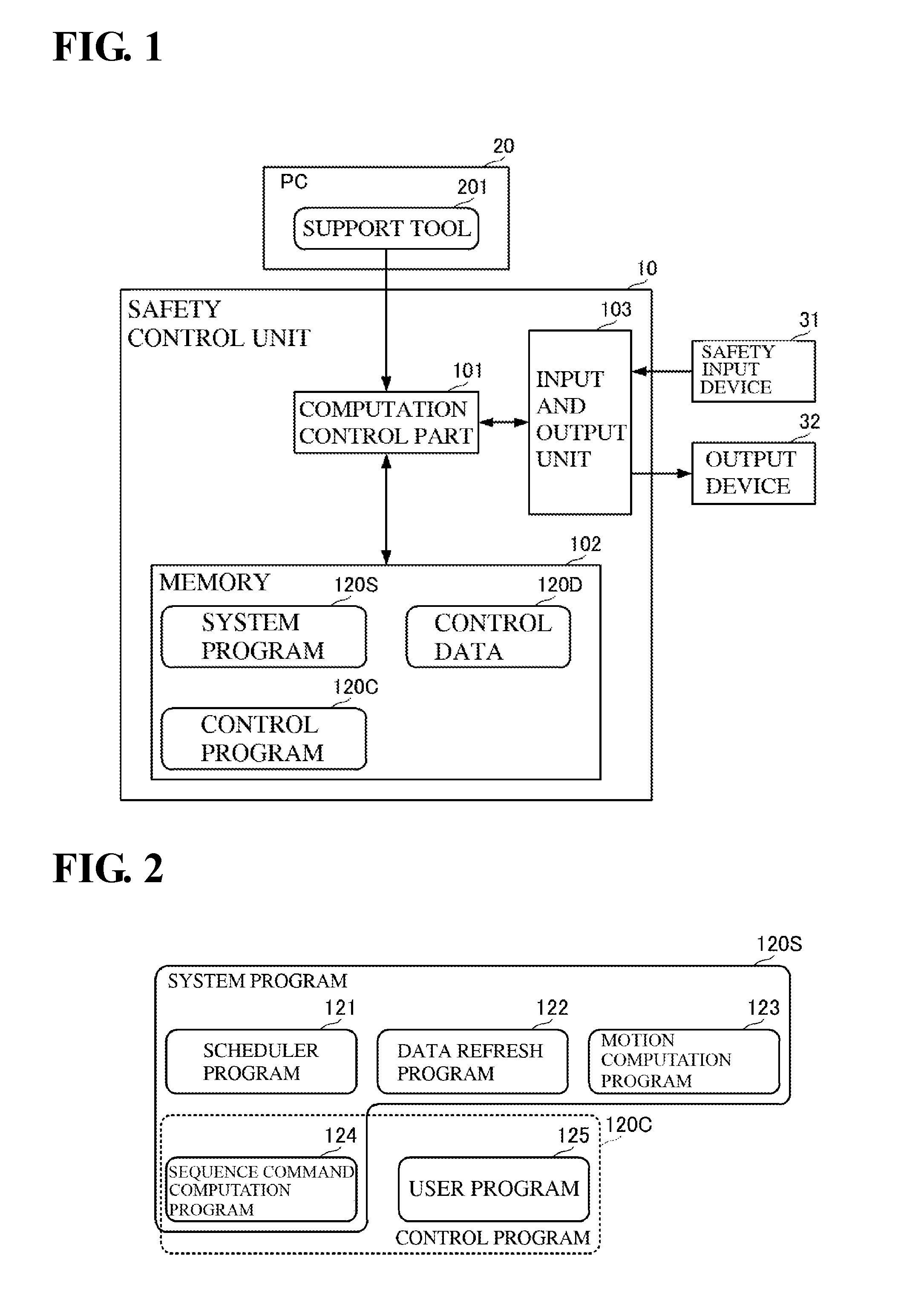
[0011] FIG. 1 is a block diagram showing a schematic configuration of a safety control system including a control unit according to an embodiment of the present invention.
[0012] FIG. 2 is a diagram showing configurations of a system program and a control program.
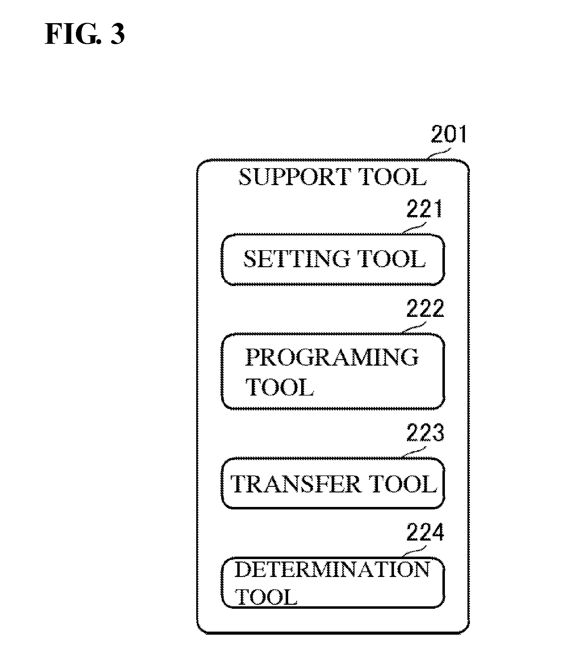
[0013] FIG. 3 is a diagram showing a configuration of a support tool.
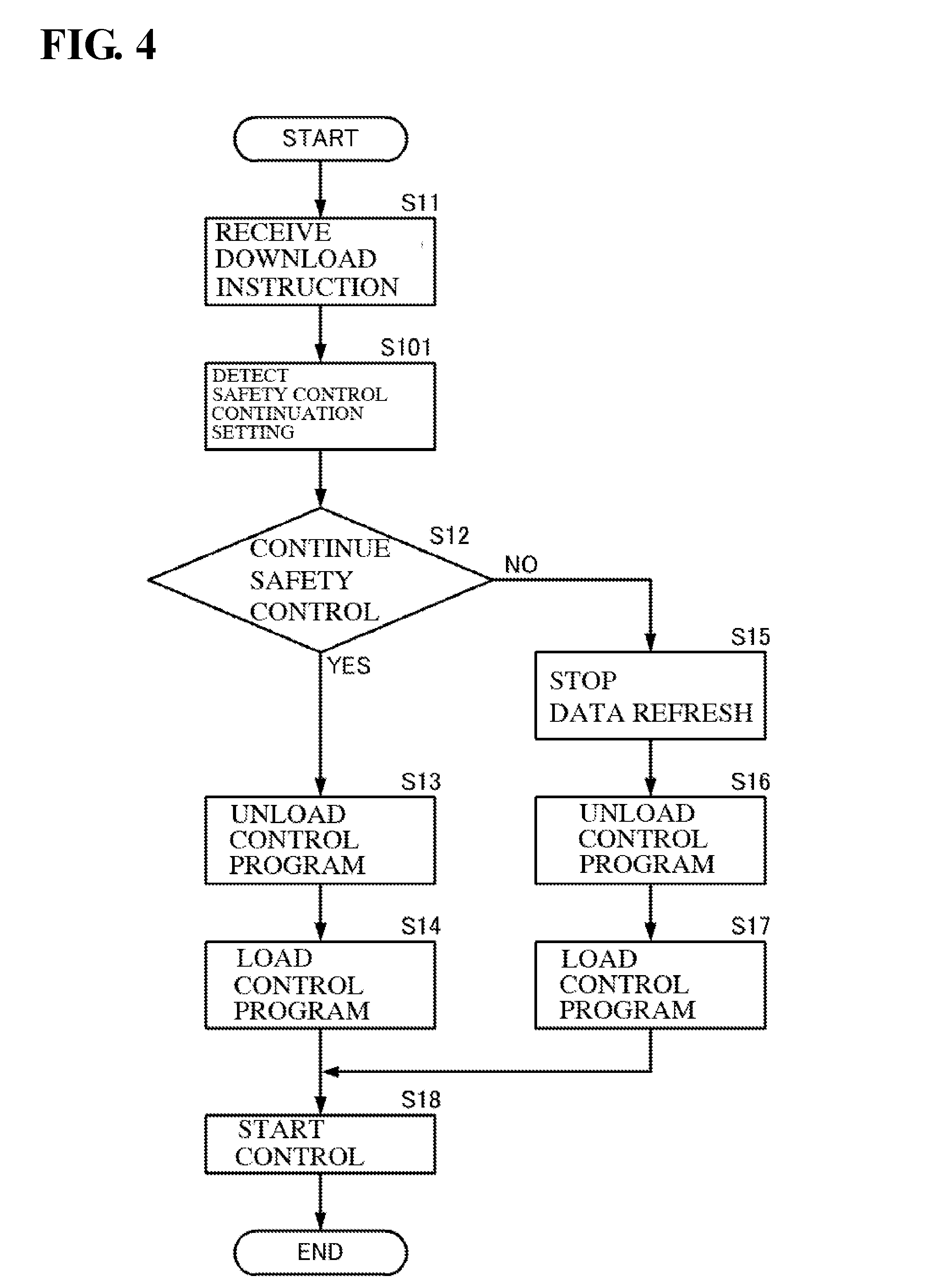
[0014] FIG. 4 is a flowchart of a safety control process in a computation control part.
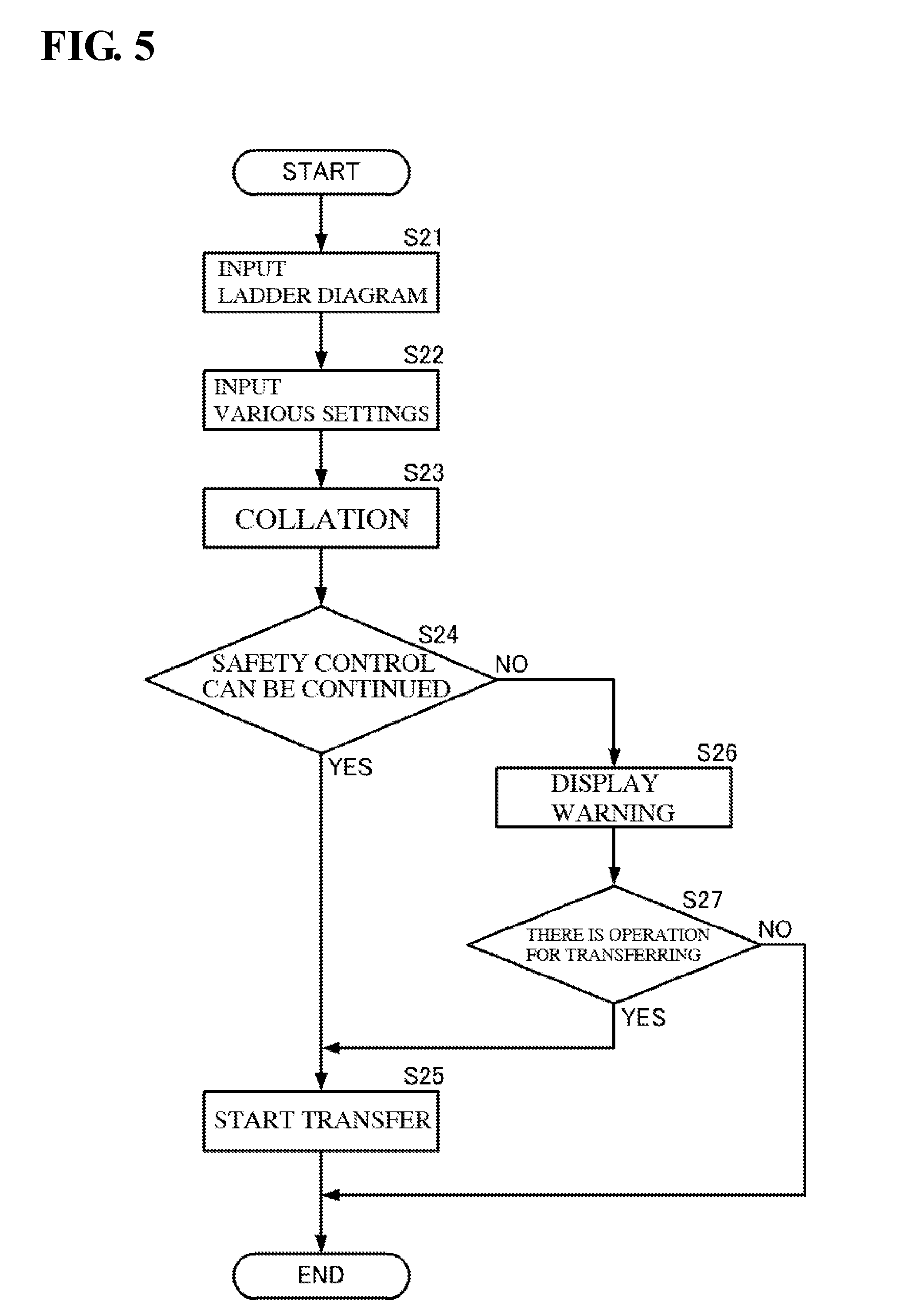
[0015] FIG. 5 is a flowchart of a program change process in the support tool.
EMBODIMENTS OF THE INVENTION
[0016] A safety control unit and a data safety control technique according to an embodiment of the present invention will be described with reference to the drawings. FIG. 1 is a block diagram showing a schematic configuration of a safety control system including a safety control unit according to the embodiment of the present invention. FIG. 2 is a diagram showing configurations of a system program and a control program. FIG. 3 is a diagram showing a configuration of a support tool.
[0017] As shown in FIG. 1, a safety control unit 10 is connected to a PC (personal computer) 20, a safety input device 31, and an output device 32. The safety control unit 10, the safety input device 31, and the output device 32 are connected through a predetermined data network. Note, that it is preferable that this data network is constituted with protocols with high connection reliability. The safety control unit 10, the safety input device 31, and the output device 32 realize a safety control system using an FA (Factory Automation) system. Note, that a general input device may be connected to this safety control system.
[0018] The safety input device 31 is a device for obtaining data for safety control, such as a light curtain or a safety switch. The output device 32 executes operations regarding safety control through relays, motors, lamps, and the like of the FA system. Note, that one safety input device 31 and one output device 32 are shown in FIG. 1, but multiple safety input devices 31 may be arranged and multiple output devices 32 may be arranged.
[0019] The safety control unit 10 and the PC 20 are locally connected via, for example, a general data communication cable. A support tool 201 is incorporated in the PC 20. The safety control unit 10 downloads programs and setting information that are created using the support tool 201.
[0020] The safety control unit 10 includes a computation control part 101, a memory 102, and an input and output unit 103.
[0021] The computation control part 101 is connected to the memory 102 and the input and output unit 103. The input and output unit 103 is connected to the safety input device 31 and the output device 32 via the above-mentioned data network.
[0022] As shown in FIG. 1, the memory 102 stores a system program 120S, a control program 120C, and control data 120D. As shown in FIG. 2, the system program 120S has a scheduler program 121, a data refresh program 122, a motion computation program 123, and a sequence command computation program 124. The control program 120C has the sequence command computation program 124 and a user program 125.
[0023] The control data 120D is referred to when the system program 120S and the control program 120C are executed. A safety control continuation setting variable 120R is a variable in which whether to continue safety control when the control data 120 D is rewritten is set, that is, whether to continue data refresh is set.
[0024] The scheduler program 121 manages the schedules of various processes that the computation control part 101 executes.
[0025] The data refresh program 122 performs batch conversion of the safety control data stored in the control data 120D in the memory 102 and the input and output unit 103, and performs batch conversion of the safety control data stored in the control data 120D in the memory 102 and the safety input device 31 and the output device 32 via the input and output unit 103. More specifically, the data refresh program 122 executes the process for reflecting the safety control data from the safety input device 31 in the control data 120D via the input and output unit 103, and executes the process for outputting output data for safety control and computation results from the motion computation program 123 and the user program 125 to the output device 32 via the input and output unit 103. Note, that the output data for safety control is used for controlling the states of the output device 32, based on input data for safety control.
[0026] The motion computation program 123 performs computations for controlling motion devices such as motors (e.g., servo motors), based on data that a general input device obtains.
[0027] The sequence command computation program 124 belongs to the system program 120S and the control program 120C, and is a program based on the ladder diagram for safety control that is created by the support tool 201.
[0028] The user program 125 executes various settings for safety control created by the support tool 201.
[0029] The computation control part 101 continuously executes the system program 120S and the control program 120C, while referring to the control data 120D. Specifically, based on the scheduler program 121, the computation control part 101 executes the motion computation program 123, the sequence command computation program 124, and the user program 125. At this time, the computation control part 101 refers to the control data 120D.
[0030] Upon completion of the execution of the motion computation program 123, the sequence command computation program 124, and the user program 125, the computation control part 101 executes the data refresh program 122. Specifically, the computation control part 101 performs, using the data refresh program 122, batch conversion of the control data 120D in the memory 102 and the safety control data of the safety input device 31 and the output device 32 via the input and output unit 103.
[0031] Upon completion of the data refresh, the computation control part 101 executes the motion computation program 123, the sequence command computation program 124, and the user program 125 with reference to the control data 120D subjected to the data conversion. The safety control of the FA system is realized by the computation control part 101 repeating this series of processes.
[0032] As shown in FIG. 3, the support tool 201 has a setting tool 221, a programing tool 222, a transfer tool 223, and a determination tool 224. The setting tool 221 is used for creating the user program 125 including the above-mentioned various settings. The programing tool is used for creating a ladder diagram, in other words, is used for creating the sequence command computation program 124. The transfer tool 223 is used for converting the user program 125 created by the setting tool 221 and the sequence command computation program 124 created by the programing tool 222 into the data format to be transferred to the computation control part 101, and is used for transferring these data. The determination tool 224 is used for determining whether the safety control needs to be stopped, that is, whether the data refresh needs to be stopped when the user program 125 and the sequence command computation program 124 are transferred.
[0033] In this configuration, if the user program 125 and the sequence command computation program 124 are to be rewritten with the changes of the various settings and the ladder diagram, the computation control part 101 executes the following processes. FIG. 4 is a flowchart of a safety control process in the computation control part.
[0034] As shown in FIG. 4, the computation control part 101 receives an instruction for rewriting the user program 125 and the sequence command computation program 124, that is, a download instruction (S11). While the computation control part 101 receives no download instruction, the computation control part 101 continuously executes, as mentioned above, the system program 120S including the data refresh and the control using the control program 120C, while referring to the control data 120D.
[0035] The computation control part 101 refers to the download instruction, and detects whether to change the control program 120C while continuing the safety control (S101).
[0036] If the detection result is setting for continuing the safety control (YES in S12), the computation control part 101 stops executing the control program 120C, and unloads the control program 120C (S13). At this time, the computation control part 101 continuously executes a part of the system program 120S including the data refresh program 122 without stopping the execution, except for the sequence command computation program 124.
[0037] Next, the computation control part 101 loads the control program 120C (the sequence command computation program 124 and the user program 125) that is downloaded from the support tool 201 (S14). At this time, the computation control part 101 continuously executes a part of the system program 120S including the data refresh program 122 without stopping the execution, except for the sequence command computation program 124.
[0038] Then, the computation control part 101 resumes executing the control program 120C (S18).
[0039] By executing these processes, if the change of the control program 120C is not related to safety control, the safety control unit 10 can change the control program 120C without temporarily stopping the data refresh. In this manner, an unnecessary temporary stop of the safety control can be prevented.
[0040] Note, that if the detection result is the setting for not continuing the safety control (NO in S12), the computation control part 101 stops executing the data refresh program 122 (S15). That is, the computation control part 101 stops safety communication to the devices related to the safety control. After that, the computation control part 101 unloads the control program 120C (S16), and loads the control program 120C that is downloaded from the support tool 201 (S17). Then, the computation control part 101 resumes executing the system program 120S and the control program 120C (S18).
[0041] With this configuration, an administrator and the like of the FA system can select whether the change of the system program 120S and the control program 120C with the stop of the safety control is needed.
[0042] In addition, as shown in FIG. 5, with the configuration shown in FIG. 3, the support tool 201 may also execute the transfer after it determines whether the stop of the safety control is needed when the control program 120 is changed. FIG. 5 is a flowchart of a program change process in the support tool.
[0043] The support tool 201 receives an input of a ladder diagram including a safety control process from a programmer using the programing tool 222 (S21). Also, the support tool 201 receives an input regarding various settings for safety control by a program using the setting tool 221 (S22). Through these processes, the control program 120C is created, which has the sequence command computation program 124 and the user program 125, and includes safety control. Note, that the order of step S21 and step S22 is not limited to this order, and may be reversed.
[0044] The support tool 201 collates, using the determination tool 224, the program that is created and changed by the support tool 201 and the program that is stored in the memory 102 of the safety control unit 10 (S23).
[0045] Based on the collation result, the support tool 201 determines, using the determination tool 224, whether the stop of the safety control is needed when the control program 120C is changed.
[0046] If it is detected that the stop of the safety control is not needed (YES in S24), the support tool 201 starts transferring the control program 120C (the sequence command computation program 124 and the user program 125) using the transfer tool 223 (S25).
[0047] If it is detected that the stop of the safety control is needed (NO in S24), the support tool 201 displays a warning on the display of the PC 20 or the like (S26).
[0048] If the support tool 201 receives an operation input for transferring from a programmer (YES in S27), the support tool 201 starts transferring the control program 120C (S25). On the other hand, if the support tool 201 receives no operation input for transferring from the programmer (NO in S27), the support tool 201 ends the process.
INDEX TO THE REFERENCE NUMERALS
[0049] 10 . . . safety control unit [0050] 20 . . . PC [0051] 31 . . . safety input device [0052] 32 . . . output device [0053] 101 . . . computation control part [0054] 102 . . . memory [0055] 103 . . . input and output unit [0056] 120C . . . control program [0057] 120D . . . control data [0058] 120S . . . system program [0059] 121 . . . scheduler program [0060] 122 . . . data refresh program [0061] 123 . . . motion computation program [0062] 124 . . . sequence command computation program [0063] 125 . . . user program [0064] 201 . . . support tool [0065] 221 . . . setting tool [0066] 222 . . . programing tool [0067] 223 . . . transfer tool [0068] 224 . . . determination tool
* * * * *
D00000
D00001
D00002
D00003
D00004
XML
uspto.report is an independent third-party trademark research tool that is not affiliated, endorsed, or sponsored by the United States Patent and Trademark Office (USPTO) or any other governmental organization. The information provided by uspto.report is based on publicly available data at the time of writing and is intended for informational purposes only.
While we strive to provide accurate and up-to-date information, we do not guarantee the accuracy, completeness, reliability, or suitability of the information displayed on this site. The use of this site is at your own risk. Any reliance you place on such information is therefore strictly at your own risk.
All official trademark data, including owner information, should be verified by visiting the official USPTO website at www.uspto.gov. This site is not intended to replace professional legal advice and should not be used as a substitute for consulting with a legal professional who is knowledgeable about trademark law.