Arrangement, Particularly Refrigerating Machine Or Heat Pump
Burk; Roland
U.S. patent application number 16/326096 was filed with the patent office on 2019-07-11 for arrangement, particularly refrigerating machine or heat pump. The applicant listed for this patent is Mahle International GmbH. Invention is credited to Roland Burk.
| Application Number | 20190212071 16/326096 |
| Document ID | / |
| Family ID | 59745244 |
| Filed Date | 2019-07-11 |


View All Diagrams
| United States Patent Application | 20190212071 |
| Kind Code | A1 |
| Burk; Roland | July 11, 2019 |
ARRANGEMENT, PARTICULARLY REFRIGERATING MACHINE OR HEAT PUMP
Abstract
An arrangement may comprise a first and second heat tank, a thermochemical reactor that is thermally and fluidically connected to the heat tank, a heat transfer fluid circuit containing a heat transfer fluid for transporting heat between the two heat tanks and the thermochemical reactor, a temporary heat store arranged in the heat transfer fluid circuit for the temporary storage of the heat transfer fluid. The temporary heat store may be designed to receive the heat transfer fluid at two different temperature levels. The temporary heat store may include a first partial store with variable storage space and a second partial store with variable storage space.
| Inventors: | Burk; Roland; (Stuttgart, DE) | ||||||||||
| Applicant: |
|
||||||||||
|---|---|---|---|---|---|---|---|---|---|---|---|
| Family ID: | 59745244 | ||||||||||
| Appl. No.: | 16/326096 | ||||||||||
| Filed: | August 16, 2017 | ||||||||||
| PCT Filed: | August 16, 2017 | ||||||||||
| PCT NO: | PCT/EP2017/000982 | ||||||||||
| 371 Date: | February 15, 2019 |
| Current U.S. Class: | 1/1 |
| Current CPC Class: | F28D 20/0034 20130101; F25B 17/08 20130101; Y02B 30/64 20130101; F28D 2020/0095 20130101; Y02E 60/14 20130101; F25B 2400/24 20130101; Y02A 30/278 20180101; F25B 30/04 20130101; Y02B 30/00 20130101; Y02A 30/27 20180101; Y02E 60/142 20130101 |
| International Class: | F28D 20/00 20060101 F28D020/00 |
Foreign Application Data
| Date | Code | Application Number |
|---|---|---|
| Aug 17, 2016 | DE | 102016215381.1 |
Claims
1. A system for an arrangement of a refrigerating machine or a heat pump, comprising: a first heat reservoir acting as a heat source and with a second heat reservoir acting as a heat sink, at least one thermochemical reactor configured to be thermally and fluidically connected to the heat reservoirs, a heat transfer fluid circuit, in which a heat transfer fluid is arranged to transport heat between the two heat reservoirs and the at least one thermochemical reactor, a temporary heat store arranged in the heat transfer fluid circuit for temporarily storing the heat transfer fluid, wherein the temporary heat store is designed to hold the heat transfer fluid with two different stratified temperature distributions between the temperatures of the heat reservoirs (T.sub.1, T.sub.2), and, for this purpose, the temporary heat store has a first partial store with a variable storage volume and has a second partial store with a variable storage volume that is thermally and fluidically separated from this, at least one, preferably two conveying device(s) available in the heat transfer fluid circuit to propel the heat transfer fluid (F) in the heat transfer fluid circuit, a valve system available in the heat transfer fluid circuit, which comprises at least one adjustable valve device, by which the heat transport between the two heat reservoirs, the thermochemical reactor and the temporary heat store can be controlled by the heat transfer fluid, a regulating/control system for controlling the valve system.
2. The system according to claim 1, at least two thermochemical reactors are available, which each comprise a separate housing, a fluid inlet, and a fluid outlet, wherein the at least two thermochemical reactors are fluidically connected to each other in parallel.
3. The system according to claims 1, wherein the valve system comprises a first adjustable valve device for each available thermochemical reactor, by which the fluid inlet of the respective thermochemical reactor can be optionally connected to the first or the second heat reservoir, and the valve system comprises a second adjustable valve device for each available thermochemical reactor, by which the fluid outlet of the respective thermochemical reactor can be optionally connected to the first or the second heat reservoir.
4. The system according to one of the claim 1, wherein the regulation/control device is set up or programmed for the time-delayed adjustment of the individual first valve devices and for the time-delayed adjustment of the individual second valve devices.
5. The system according to claim 1, further comprising an equalizing reservoir arranged in the heat transfer fluid circuit to hold the heat transfer fluid.
6. The system according to claim 1, wherein the first valve devices and the second valve device are each designed as a 3/2-way switching valve.
7. The system according to claim 6, wherein at least a 3/2-way valve is designed as an automatically switching valve.
8. The system according to claim 1, wherein the temporary heat store is fluidically connected in parallel with the second valve directions so that the fluid inlet of the first heat reservoir fluidically communicates with the first partial store and the fluid inlet of the second heat reservoir fluidically communicates with the second partial store.
9. The system according to claim 1, wherein the temporary heat store is designed to simultaneously hold and output a first and a second fluid mass of the heat transfer fluid, and wherein both fluid masses have different temperature levels or temperature stratifications.
10. The system according to claim 1, wherein the first partial store of the temporary heat store is fluidically connected to the first heat reservoir and the second partial store of the temporary heat store is fluidically connected to the second heat reservoir.
11. The system according to claim 1, wherein the volume-variable first partial store is designed to be complementary to the volume-variable second partial store so that the overall volume formed by the two partial stores is constant.
12. The system according to claim 1, wherein the temporary heat store is designed as a reservoir, wherein the reservoir comprises: a housing, in the interior space of which a separation element is movably arranged, which divides the interior space into a volume-variable first partial store and a second partial store, which is also volume-variable and their medically insulated from the first partial store, a first through-opening available in the housing for introducing and discharging a heat transfer fluid with a first temperature level or a temperature stratification subsequent to it into or out of a first partial store, and a second through-opening available in the housing for introducing and discharging a heat transfer fluid with a second temperature level or a temperature stratification subsequent to it into or out of a second partial store, wherein the volume-variable first partial store is designed to be complementary to the volume-variable second partial store so that the overall volume formed by the two partial stores is constant.
13. The system according to claim 12, wherein a first sensor element is provided on the first through-opening, by which, it can be determined whether the separation element is located in a first end position, in which the separation element has a minimum distance away from the first through-opening and/or that a second sensor element is provided on the second through-opening, by which, it can be determined whether the separation element is located in a second end position, in which the separation element has a minimum distance away from the second through-opening.
14. The system according to claim 13, wherein an operating state can be set by the regulation/control device in the at least one adjustable valve device of the valve system, in which the heat transfer fluid circuit forms a first partial circuit and in which the heat transfer fluid transports heat between the thermochemical reactor and the second heat reservoir so that heat is transferred from the thermochemical reactor into the second heat reservoir.
15. The system according to claim 14, wherein, in the operating state, the first partial store has a maximum volume and the second partial store has a minimum volume.
16. The system according to claim 1, wherein an operating state can be set by the regulation/control device in the at least one adjustable valve device of the valve system where, in which the heat transfer fluid circuit forms a second partial circuit, in which the heat transfer fluid transports heat between the thermochemical reactor and the first heat reservoir so that heat is transferred from the first heat reservoir into the thermochemical reactor.
17. The system according to claim 16, wherein, in the operating state, the second partial store has a maximum volume and the first partial store has a minimum volume.
18. The system according to claim 1, wherein an operating state can be set by the regulation/control device in the at least one adjustable valve device of the valve system wherein: heat transfer fluid is transported from the first partial store into the first heat reservoir, heat transfer fluid is transported from the first heat reservoir into the thermochemical reactor, and heat transfer fluid is transported from the thermochemical reactor into the second partial store.
19. The system according to claim 1, wherein an operating state can be set by the regulation/control device in the at least one adjustable valve device of the valve system, wherein: heat transfer fluid is transported from the second partial store into the second heat reservoir, heat transfer fluid is transported from the second heat reservoir into the thermochemical reactor, and heat transfer fluid is transported from the thermochemical reactor into the first partial store.
20. A method to operate an arrangement of a heat transfer fluid circuit comprising: providing at least one thermochemical reactor, two heat reservoirs with different temperature levels (T.sub.1, T.sub.2) and a temporary heat store, wherein the temporary heat store comprises two thermally and fluidically separated partial stores, in which a heat transfer fluid available in the heat transfer fluid circuit can be taken on being thermally a fluidically separated from one another; supplying heat from the first heat reservoir into the thermochemical reactor by taking heat transfer fluid temporarily stored in the first partial store of the temporary heat store and supplying heat transfer fluid to the first heat reservoir and, at the same time, dissipating heat transfer fluid from the thermochemical reactor and introducing the heat transfer fluid into the second partial store of the temporary heat store; and dissipating heat from the at least one thermochemical reactor into the second heat reservoir, by taking heat transfer fluid temporarily stored in the second partial store of the heat transfer fluid and supplying heat transfer fluid to the second heat reservoir and, at the same time, dissipating heat transfer fluid from the thermochemical reactor and introducing heat transfer fluid into the first partial store of the temporary heat store.
21. The method according to claim 20, wherein at least two thermochemical reactors are available, which each comprise a separate housing, a fluid inlet, and a fluid outlet, wherein the at least two thermochemical reactors are fluidically connected to each other in parallel, the valve system comprises a first adjustable valve device for each available thermochemical reactor, by which the fluid inlet of the respective thermochemical reactor can be optionally connected to the first or the second heat reservoir, the valve system comprises a second adjustable valve device for each available thermochemical reactor, by which the fluid outlet of the respective thermochemical reactor can be optionally connected to the first or the second heat reservoir, wherein, in accordance with switching the first existing valve devices to connect the thermochemical reactors to the first or the second heat reservoir takes place in a time-delayed manner, and wherein, in accordance with switching the first existing valve devices to connect the thermochemical reactors to the first or the second heat reservoir takes place in a time-delayed manner.
22. The method according to claim 21, wherein the time-delayed switching of the first and the second valve devices takes place in such a way that at least one of the thermochemical reactors and a maximum of two of the available thermochemical reactors simultaneously have the temperature level of the first heat reservoir.
Description
CROSS-REFERENCE TO RELATED APPLICATIONS
[0001] This application claims priority to International Application PCT/EP2017/000982 filed on Aug. 16, 2017 and to German Application DE 10 2016 215 381.1 filed on Aug. 17, 2016, the contents of each are hereby incorporated by reference in their entirety.
TECHNICAL FIELD
[0002] The invention relates to an arrangement, in particular, a refrigerating machine or a heat pump, as well as a method for operating this arrangement.
[0003] Thermally powered sorption refrigerating systems have a high energy savings potential since inexpensive waste or excess heat is used and, in this way, expensive mechanical drive energy can be saved. In the case of stationary applications, the electrical networks can be relieved, particularly in warm time zones and climate zones with a high level of cooling demand. In the cold season, the systems can also be used as heat pumps, which boost additional environmental heat to a temperature level sufficient for heating purposes by means of burner heat.
BACKGROUND
[0004] Against this background, from the most recent background art, apparatuses are known where porous solid materials are used, which react with a working material subject to the implementation of heat and do not have any moving and thereby fault-prone wear parts within the range of the working material.
[0005] However, with relation to continuously working absorption systems, adsorption heat pumps or adsorption refrigerating systems implemented with the aid of such thermochemical reactors have the disadvantage that the periodic temperature changes with cycled thermal masses result in efficiency compromises, which reduce the achieved power density or power efficiency.
[0006] In this context, DE 102006043715 A1 discloses an adsorption heat pump where a stratified heat store is used. This allows for a time-delayed storage and reuse of sensitive and latent heat during the adsorption cycle. However, such stratified heat stores cannot be used everywhere due to its great volume.
[0007] It is the object of the present invention to indicate new ways to develop sorption heat pumps and sorption refrigeration systems, in particular, having improved efficiency.
[0008] This task is achieved by means of the object of the independent patent claims. Favourable embodiments are the object of the dependent patent claims.
SUMMARY
[0009] The basic idea of the invention is to equip an arrangement of an adsorption heat pump or an adsorption refrigerating machine based on cyclically operating thermochemical reactors with a temporary heat store, which has two partial stores to hold a heat transfer fluid at two different temperature levels. This temporary heat store is used to temporarily store heat contained in the heat transfer fluid in the case of thermally cycling the thermochemical reactor and in the case of switching the thermochemical reactor between two different temperature levels associated therewith. Under the term "thermochemical reactor", in general, a reservoir with at least one working material and one integrated heat transfer structure is understood, using with at least on exothermic or endothermic reaction or phase change can be instigated independently of a marginal temperature condition subject to the supply and dissipation of heat. Thereby, it can have to do with a sorption reactor or a phase changer, in particular, a condenser and/or a vaporiser. Such special embodiments, components or subcomponents are also known under the terms "sorber", "sorption reactor", "thermochemical store" or "phase changer".
[0010] The present temporary heat store according to the invention that is used allows for the temporary storage of the heat transfer fluid at the temperature level of a heat source of the arrangement in the first partial store and the simultaneous temporary storage of the heat transfer fluid at the temperature level of a heat sink of the arrangement in the second partial store of the temporary heat store.
[0011] In the case of the temporary heat store according to the invention, a volume reduction of the second partial store is associated with a volume increase of the first partial store and vice versa. Since both volume-variable partial stores comprise the same overall volume, introducing the heat transfer fluid at the temperature level of the heat source into the first subspace makes discharging the heat transfer fluid at the second temperature level from the second partial store easier and vice versa. In this way, undesired energy loss of the thermochemical reactor during thermal cycling, meaning when switching over between the two temperature levels of the heat source and the heat sink can be minimized. In the result, this leads to an improved efficiency of the arrangement according to the invention with relation to conventional arrangements.
[0012] An arrangement according to the invention, in particular, a refrigerating machine or a heat pump, comprises a first heat reservoir, which acts as a heat source as well as a second heat reservoir, which acts as a heat sink. The arrangement furthermore comprises at least one thermochemical reactor, which is or can be thermally and fluidically connected to the heat reservoirs. Preferably, the thermochemical reactor is an adsorption refrigerating machine or an adsorption heat pump or is a crucial functional component thereof.
[0013] Furthermore, the arrangement comprises a heat transfer fluid circuit, in which a heat transfer fluid is arranged to transport heat between the two heat reservoirs and the thermochemical reactor. A temporary heat store is provided in the heat transfer fluid circuit to temporarily store the heat transfer fluid. According to the invention, the temporary heat store comprises a first partial store with a variable storage volume. Furthermore, the temporary heat store comprises a second partial store with a variable storage volume that is thermally and fluidically separated from the first partial store.
[0014] At least one, preferably two conveying device(s) of the arrangement according to the invention available in the circuit is used to propel the heat transfer fluid in the heat transfer fluid circuit. Furthermore, the arrangement comprises a valve system that is available in the heat transfer fluid circuit and comprises at least one adjustable valve device. By means of this at least one adjustable valve device, the heat transport between the two heat reservoirs, the thermochemical reactor and the temporary heat store can be controlled by means of the heat transfer fluid. For controlling the said valve system, the arrangement according to the invention only comprises a regulation/control device.
[0015] In a preferred embodiment, at least two thermochemical reactors are provided, which each comprise a separate reservoir with a heat transfer structure with a fluid inlet and a fluid outlet. The at least two thermochemical reactors are thereby arranged with a fluidic parallel connection to one another, meaning the fluid inlets and the fluid outlets of the at least two thermochemical reactors are or can be fluidically connected to each other by means of the valve system. The provision of two or a greater number of separate thermochemical reactors allows for a time-delayed switching of the available thermochemical reactors from a state with a higher temperature T.sub.1 into a state with a temperature T.sub.2 that is relatively lower than temperature T.sub.1. The time-delayed switching of the individual thermochemical reactors results in a particularly low energy loss during the temperature change in connection with the temporary heat store.
[0016] In the case of a favourable further embodiment, the valve system comprises a first adjustable valve device for each available thermochemical reactor, by means of which the fluid inlet of the respective thermochemical storage can be optionally connected to the first or the second heat reservoir. In the case of this variant, the valve system comprises a second adjustable valve device for each available thermochemical reactor, by means of which the fluid outlet of the respective thermochemical reactors can be optionally connected to the first or the second heat reservoir. This measure allows for a favourable control of the time-delayed switching process between exothermic and endothermic subprocesses running at different temperature levels.
[0017] Being particularly preferred, the regulation/control device is set up/programmed for the time-delayed adjustment of the individual first valve devices and for the time-delayed adjustment of the individual second valve devices. This means that the regulation/control device is capable of adjusting the first and second valve devices via suitable control lines individually, meaning independently of one another. The regulation/control device can comprise a control unit or a storage unit. In the latter, a computer programme code can be stored, which is processed by the control unit to carry out the time-delayed switching process of the individual first and second valve devices. In the said computer program code, the algorithm for the time-delayed switching of the first and the second valve devices is thereby coded.
[0018] Expediently, the temporary heat store is fluidically connected in parallel to the second valve devices in such a way that the fluid inlet of the first heat reservoir fluidically communicates with the first partial store and the fluid inlet of the second heat reservoir fluidically communicates with the second partial store.
[0019] In a favourable further embodiment, the first valve device and the second valve device each comprise a 3/2-way valve. This allows for a simple implementation of an optional fluidic connection of the at least one thermochemical reactor either with a first heat reservoir at temperature level T.sub.1 or the second heat reservoir at temperature level T.sub.2.
[0020] In another preferred embodiment, an equalizing reservoir is arranged in the heat fluid circuit to hold the heat transfer fluid.
[0021] In the case of another preferred embodiment, the temporary heat store is designed to simultaneously hold and output a first and a second fluid mass of the heat transfer fluid, wherein the two fluid masses can have various temperature stratifications between the temperature limits T.sub.1 and T.sub.2. This makes it possible to simultaneously temporarily store fluid mass within the temporary heat store for carrying out an energy-efficient temperature change between the temperature level of the heat sink and the heat source.
[0022] Being particularly favourable, the first partial store of the temporary heat store is fluidically connected to the first heat reservoir and the second partial store of the temporary heat store is fluidically connected to the second heat reservoir.
[0023] This measure allows for a simple supply of heat transfer fluid near the temperature T.sub.1 from a thermochemical reactor to be cooled into the temporary heat store. This measure also allows for a simple supply of heat transfer fluid near the temperature T.sub.2 from a thermochemical reactor to be heated into the temporary heat store.
[0024] In accordance with a particularly preferred embodiment, the temporary heat store is designed as a reservoir. In the case of this variant, the reservoir comprises a housing, in the interior space of which a separation element is movably arranged, which divides the interior space into a volume-variable first partial store and a second partial store, which is also volume-variable and is thermally insulated from the first partial store. A first through-opening is provided in the housing for the introduction and discharge of the heat transfer fluid into the or from the first partial store. Furthermore, a second through-opening is provided in the housing for the introduction and discharge of the heat transfer fluid into the or from the second partial store.
[0025] In the case of a favourable further embodiment, the housing is designed to be oblong. Thereby, the first through-opening is arranged on a first longitudinal end and the second through-opening is arranged on a second longitudinal end situated opposite to the first longitudinal end. The large length/sectional ratio associated with an oblong shape of the housing serves the purpose that a temperature stratification of the fluid mass flowing in and out remains constant to a great extent and does not notably mix during the required storage time.
[0026] Expediently, the housing can be designed as a pipe body, which essentially extends in a straight line along an axial direction. In the case of this variant, the separation element abuts the inner side of a circumferential wall of the pipe body to form the two volume-variable partial stores along the axial direction in a moveable manner. Such a construction is easy to manufacture on a technical level, thereby being associated with low manufacturing costs.
[0027] In another favourable further embodiment, a first sensor element is provided on the first through-opening, by means of which it can be determined whether the separation element is situated in a first end position, in which the separation element has a minimum distance away from the first through-opening. In addition or as an alternative, in the case of this variant, a second sensor element can be provided on the second through-opening, by means of which it can be determined whether the separation element is situated in a second end position, in which the separation element has a minimum distance away from the second through-opening. In this way, in the case of thermal cycling the thermochemical reactor, it can be determined when the heat transfer fluid has been completely taken from the two partial stores, because, in this case, the separation element is situated at a minimum distance away from the first or the second through-opening.
[0028] In the case of a preferred embodiment of the arrangement, an operating state can be set by the regulation/control device in the at least one adjustable valve device of the valve system, in which the heat transfer fluid circuit forms a first partial circuit. In this first partial circuit, the heat transfer fluid circulates between the thermochemical reactor and the second heat reservoir, and that being in such a way that heat is transferred from the thermochemical reactor into the second heat reservoir, meaning into the heat sink. In this way, heat can be dissipated from the thermochemical reactor in a particularly effective way.
[0029] Preferably, in this operating state, the first partial store has a maximum volume and the second partial store has a minimum volume. This means that the first partial store is filled with the heat transfer fluid, which has a temperature stratification near the temperature level of the heat source.
[0030] In the case of another preferred embodiment of the arrangement, an operating state can be set by the regulation/control device in the at least one adjustable valve device of the valve system, in which the heat transfer fluid circuit forms a second partial circuit. In this second partial circuit, the heat transfer fluid circulates between the thermochemical reactor and the first heat reservoir so that heat is transferred from the first heat reservoir, meaning from the heat source, into the thermochemical reactor.
[0031] Preferably, in this operating state, the second partial store has a maximum volume and the second partial store has a minimum volume. This means that the second partial store is filled with the heat transfer fluid, which has a temperature stratification near the temperature level of the heat sink.
[0032] In the case of another preferred embodiment of the arrangement, an operating state can be set by the regulation/control device in the at least one adjustable valve device of the valve system where heat transfer fluid is transported from the first partial store of the temporary heat store into the first heat reservoir. At the same time, heat transfer fluid from the first heat reservoir is transported into the thermochemical reactor and heat transfer fluid is transferred from the thermochemical reactor into the second partial store. In this way, heat can be supplied to the thermochemical reactor in a particularly effective manner and, thereby, the sensitive heat with a lower temperature can be stored for a later cooling process.
[0033] In the case of another preferred embodiment of the arrangement, and operating state can be set by the regulation/control device in the at least one adjustable valve device of the valve system where heat is transferred from the second partial store into the second heat reservoir by means of the heat transfer fluid. At the same time, heat from the second heat reservoir is transported into the thermochemical reactor and from the thermochemical reactor into the first partial store by means of the heat transfer fluid. In this way, heat can be discharged from the thermochemical reactor in a particularly efficient manner and, thereby, the sensitive heat with a higher temperature can be stored for a later heating process.
[0034] In a favourable further embodiment, the first and the second heat reservoir as well as the thermochemical reactor each comprise a fluid inlet and a fluid outlet for the introduction and discharge of the heat transfer fluid. In the case of this variant, the heat transfer fluid circuit comprises a first adjustable valve device, by means of which the fluid inlet of the thermochemical reactor can be optionally connected to the fluid outlet of the first or second heat reservoir. The heat transfer fluid circuit also comprises a second adjustable valve device, by means of which the fluid outlet of the thermochemical reactor can be optionally connected to the fluid inlet of the first or second heat reservoir.
[0035] The invention furthermore relates a method for operating an arrangement, preferably the one presented in the above, having a heat transfer fluid circuit, in which at least one thermochemical reactor, two heat reservoirs with different temperatures and a temporary heat store are arranged and are fluidically connected to one another by means of a heat transfer fluid circuit.
[0036] The temporary heat store used for carrying out the method according to the invention comprises two thermally and fluidically separate partial stores, in which a heat transfer fluid circulating within the heat transfer fluid circuit can be accepted and discharged in a way that is thermally and fluidically separated from one another. In accordance with the method according to the invention, in order to supply heat from the first heat reservoir into the thermochemical reactor by means of the heat transfer fluid, heat transfer fluid that is temporarily stored within the first partial store of the temporary heat store is taken and supplied to the first heat reservoir. At the same time, heat transfer fluid is discharged from the thermochemical reactor and introduced into the second partial store of the temporary heat store.
[0037] In order to carry out a temperature change of the thermochemical reactor from a high to a lower temperature level, increasingly cooler heat transfer fluid temporarily stored in the second partial store of the temporary heat store is taken and fed to the heat sink. At the same time, initially cool however increasingly warmer heat transfer fluid is discharged from the thermochemical reactor and introduced into the first partial store of the temporary heat store. In order to carry out a temperature change of the thermochemical reactor from a low to a higher temperature level, increasingly warmer heat transfer fluid temporarily stored in the first partial store of the temporary heat store is taken and fed to the heat source. At the same time, initially cool however increasingly warmer heat transfer fluid is discharged from the thermochemical reactor and introduced into the second partial store of the temporary heat store in a thermally stratified manner.
[0038] In a preferred embodiment of the method, at least two thermochemical reactors are available, which each comprise a separate housing as well as a fluid inlet and a fluid outlet. In the case of this variant, the at least two thermochemical reactors are fluidically connected to each other in parallel.
[0039] Thereby, the valve system comprises a first adjustable valve device for each available thermochemical reactor, by means of which the fluid inlet of the respective thermochemical reactor can be optionally connected to the first or the second heat reservoir. The valve system comprises a second adjustable valve device for each available thermochemical reactor, by means of which the fluid outlet of the respective thermochemical reactor can be optionally connected to the first or the second heat reservoir. The switching of the first existing valve devices to connect the thermochemical reactors to the first or the second heat reservoir takes place in a time-delayed manner. The switching of the available second valve devices to connect the thermochemical reactors to the first or the second heat reservoir also takes place in a time-delayed manner. The time-delayed switching of the individual thermochemical reactors makes a time-delayed regeneration of sensitive heat possible in connection with the temporary heat store, thereby resulting particularly low loss during the temperature change.
[0040] Other important features and advantages of the invention result from the subclaims, the drawings and the related figure description based on the drawing.
[0041] It is to be understood that the features explained in the aforementioned and following cannot only be used in the respectively indicated combination, but also in other combinations or alone, without departing from the scope of the present invention.
[0042] Preferred exemplary embodiments of the invention are represented in the drawings and will be described in more detail in the following description, wherein the same reference numbers will refer to the same or similar or functionally identical components.
BRIEF DESCRIPTION OF THE DRAWINGS
[0043] On a schematic level respectively, the figures show
[0044] FIG. 1 to 4 arrangement according to the invention in various operating states,
[0045] FIG. 5 the construction of a temporary heat store according to the invention of the arrangement in FIGS. 1 to 4 in a detailed view,
[0046] FIG. 6 a first variation of the temporary heat store in FIG. 5,
[0047] FIG. 7 a second variation of the temporary heat store in FIG. 5,
[0048] FIG. 8-11 a variant of the arrangement of FIGS. 1 to 4 with a plurality of thermochemical reactors, which can be switched to one another in a time-delayed manner.
DETAILED DESCRIPTION
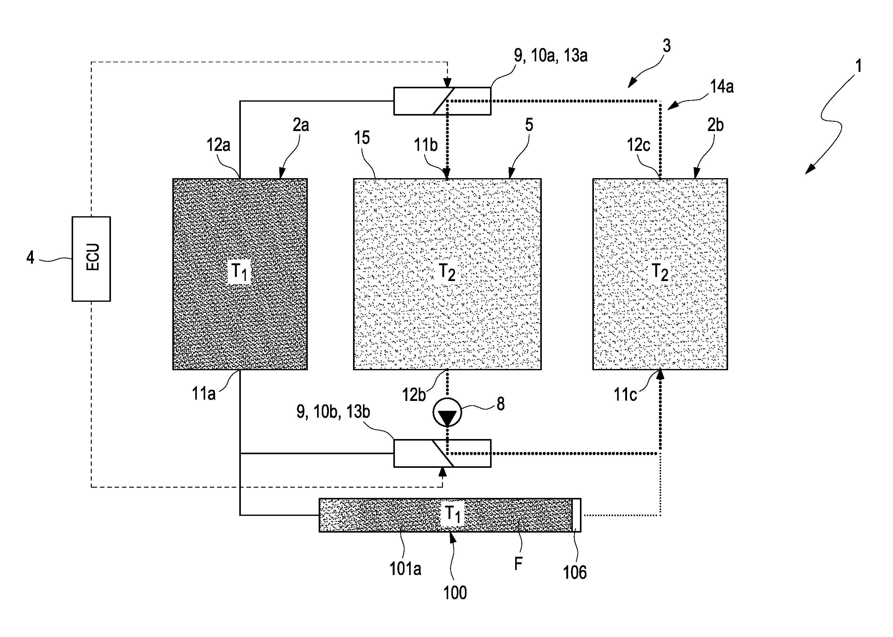
[0049] FIG. 1 shows an example of an arrangement 1 according to the invention, in particular, of a refrigerating machine or of a heat pump. The arrangement 1 comprises a first heat reservoir 2a with a first temperature T.sub.1 and a second heat reservoir 2b with a second temperature T.sub.2. Furthermore, the arrangement 1 comprises a thermochemical reactor 5, which is or can be thermally and fluidically connected to both heat reservoirs 2a, 2b. For this purpose, the arrangement 1 comprises a heat transfer fluid circuit 3, in which a heat transfer fluid F is arranged to transport heat between the two heat reservoirs 2a, 2b and the thermochemical reactor 5.
[0050] Under "thermochemical reactor", in the present document, an apparatus is understood, in which conversion processes are instigated by supplying and dissipating heat at different temperatures T.sub.1, T.sub.2--also known by the person skilled in the art as reaction heat, sorption heat, or phase change heat. The thermochemical reactor 5 can comprise a reservoir 15, which is only schematically shown in the figures, in which thermochemical reactions take place, with a heat transfer structure for the supply and dissipation of the reaction heat. The first temperature T.sub.1 comprises a greater value than the second temperature T.sub.2, meaning the first heat reservoir 2a acts as a heat source, from which heat can be transferred to the thermochemical reactor 5 by means of the heat transfer fluid F. In contrast, the second heat reservoir 2b acts as a heat sink, at which heat can be transferred from the thermochemical reactor 5 by means of the heat transfer fluid F.
[0051] Furthermore, a temporary heat store 100 is available in the heat transfer fluid circuit 3 for temporarily storing the heat transfer fluid F. The temporary heat store 100 makes a temperature change of the thermochemical reactor 5 possible with very little energy loss from temperature T.sub.1 to temperature T.sub.2 and vice versa.
[0052] The construction of the temporary heat store 100 is shown in a schematic detailed illustration in FIG. 5. In accordance with FIG. 4, the temporary heat store 100 has a first partial store 101a with a variable storage volume 102a and has a second partial store 101b with a variable storage volume 102a that is thermally and fluidically separated from this. The volume-variable first partial store 101a of the temporary heat store 100 is designed to be complementary to the volume-variable second partial store 101b so that the overall volume formed by the two partial stores 101a, 101b is always constant.
[0053] The temporary heat store 100 can also be referred to as a sensitive short-term heat store, regenerator or temperature changer and represents a component of the arrangement 1 according to the invention, which initially makes a temperature change in the thermochemical reactor 5 with low levels of energy losses at all possible.
[0054] The temporary heat store 100 is designed to simultaneously hold and output a first and a second fluid mass of the heat transfer fluid F with variously stratified temperature profiles. The temporary heat store 100 is designed to simultaneously hold and output a first and a second fluid mass of the heat transfer fluid F, wherein both fluid masses have different temperature stratifications, which are qualitatively characterized with different grey shades. The darker the grey shade, the higher the present local temperature level is.
[0055] FIG. 6 shows a further embodiment of the reservoir 103 in FIG. 5. In the case of the reservoir 103 in FIG. 2, a coil-like structure 113 is arranged in the interior space 107 of the housing 104. The coil-like structure 113 gives the interior space 107 the geometry of a fluid channel 114 with a coil-like geometry. The fluid channel 114 is thereby delimited by the coil-like structure 113 and by the housing 104, in particular, by its circumferential wall 111. The coil-like structure 103 can be designed as an insert 115 arranged in the interior space. The coil-like structure 113 can comprise at least ten windings 116, preferably even at least 20 windings. The separation element 106 is designed to be adjustable along the coil-like fluid channel 114. That means that the geometrical shape of the separation element 106 is selected in such a way that, within the interior space 107, it is adjustable along the fluid channel 114, which is delimited by the circumferential wall 111 and the coil-like structure 113.
[0056] FIG. 7 shows another variant of the example of FIG. 5, where the reservoir 103 is designed as a hose-like body 117, which at least portionally extends along an extension direction E in a non-linear manner. In the case of this variant, the separation element 106 abuts the inner side 112 of a circumferential wall 111 of the pipe-shaped body 117 to form the two volume-variable partial stores 101a, 101b along the extension direction E in a moveable manner. This variant makes a particularly spatially compact arrangement of the reservoir 103. Preferably, a length of the housing 104 or of the hose-like body 117 measured along the extension direction E is at least ten times, preferably at least twenty times a transverse direction Q measured transversely to the extension direction E.
[0057] As is evident in FIG. 1, the first partial store 101a of the temporary heat store 100 is fluidically connected to the first heat reservoir 2a. In contrast, the second partial store 101b of the temporary heat store 100 is fluidically connected to the second heat reservoir 2b.
[0058] The functional principle of the temporary heat store 100 is based on a thermally insulated fluid reservoir with end-side openings and a large length/cross-sectional ratio, within which an insulating displaceable separating body is arranged, as is schematically shown in FIG. 5.
[0059] In the example scenario in FIG. 5, the temporary heat store 100 is designed as a reservoir 103. This reservoir 103 comprises a housing 104. The housing 104 delimits an interior space 107, in which a separation element 106 is moveably arranged, which thermally and fluidically insulates both partial stores 101a, 101b from each other. The separation element 106 divides the interior space 107 into a volume-variable first partial store 101a and a second partial store 101b, which is also volume-variable and is thermally and fluidically insulated from the first partial store 101a. Preferably, the separation element 106 of the temporary heat store 100 is arranged in such a way that it can be displaceably moved easily in the longitudinal and extension direction in a fluid-tight manner to the greatest extent possible due to pressure differences between the two partial stores.
[0060] As can be recognized in the figures, the thermochemical reactor 5 and the temporary heat store 100 each have separate reservoirs 15 and 103.
[0061] As can be recognized in FIG. 5, a first through-opening 108a is available in the housing 104 for introducing and discharging the heat transfer fluid F at temperature T.sub.1 into the first partial store 101a or out of the first partial store 101a. Furthermore, a second through-opening 108b is available in the housing 104 for introducing and discharging the heat transfer fluid F with the temperature T.sub.2 into the second partial store 101b or out of the second partial store 101b.
[0062] The housing 104 is designed as a pipe body 105, which extends in a straight line along an axial direction A. The separation element 106 abuts the inner side 112 of a circumferential wall 111 of the pipe body 105 to form the two volume-variable partial stores 101a, 101b along the axial direction A in a moveable manner. The first through-opening 108a is arranged on a first longitudinal end 109a. The second through-opening 108b is arranged on a second longitudinal end 109b situated opposite to the first longitudinal end 109a.
[0063] As FIG. 3 illustrates, in the case of a separation element 106 arranged at the far left, meaning on the first through-opening 108a, the temporary heat store 100 can be filled with a temperature-stratified fluid column of the heat transfer fluid F, wherein the temperature level at the separation element approximately corresponds to temperature T.sub.2 and the temperature level at the outlet 108b almost reaches temperature T.sub.1. In accordance with FIG. 4, the separation element 106 can be pushed to the right, towards the second through-opening 108b by a heat transfer fluid F flowing from the left via the first through-opening 108a, which is initially hot, but thereby increasingly becomes cooler, whereby the temporary heat store 100 is filled with a temperature-stratified fluid column of the heat transfer fluid F, wherein the temperature level at the separate element approximately corresponds to temperature T.sub.1 and the temperature level at the outlet 108b almost reaches temperature T.sub.2. At the same time, the liquid column stratified from temperature T.sub.1 to temperature T.sub.2 is pressed to the right through the second through-opening 108b until the separation element 106 is located on the second through-opening 108b and the temperature-stratified liquid column of the heat transfer fluid F has completely been replaced.
[0064] The temperature profiles of the liquid columns of the heat transfer fluid F stored in the partial store of the temporary heat store causes that, in the case of pressing the temperature-stratified liquid column out of the second partial store, initially warm and then, however, increasingly cooler heat transfer fluid is pressed out. Thereby, this partial store can be used for the gradual cooling of a thermochemical reactor 5.
[0065] Complementary to this, in the case of pressing the temperature-stratified liquid column out of the first partial store, initially cool and then, however, increasingly warmer heat transfer fluid is pressed out. Thereby, this partial store can be used for the gradual heating of a thermochemical reactor 5.
[0066] According to FIG. 5, a first sensor element 110a is provided on the first through-opening of the temporary heat store, by means of which it can be determined whether the separation element 106 is located in a first end position, in which it has a minimum distance away from the first through-opening 108a. In an analogous manner, a second sensor element 110b can be provided on the second through-opening 108b, by means of which it can be determined whether the separation element 106 is located in a second end position, in which the it has a minimum distance away from the second through-opening 108b.
[0067] When now viewing FIG. 1 again, it can be recognized that a conveying device 8 to drive the h F is provided in the heat transfer fluid circuit 3.
[0068] In the heat transfer fluid circuit 3, furthermore, a valve system 9 is available, which comprises a first adjustable valve device 10a and a second adjustable valve device 10b. By means of the two valve devices 10a, 10b, the heat transport between the two heat reservoirs 2a, 2b, the thermochemical reactor 5 and the temporary heat store 100 can be set and controlled as a result. In order to control the valve devices 10a, 10b of the valve system 9, a regulation/control device 4 is provided, which interacts which works together with the valve devices 10a, 10b.
[0069] The first and the second heat reservoir 2a, 2b as well as the thermochemical reactor 5 each comprise a fluid inlet 11a, 11b, 11c and a fluid outlet 12a, 12b, 12c for introducing and discharging the heat transfer fluid.
[0070] By means of the first adjustable valve device 10a, the fluid inlet 11b of the thermochemical reactor 5 can be optionally connected to the fluid outlet 12a, 12c of the first or the second heat reservoir 2a, 2b. By means of the second adjustable valve device 10b, the fluid outlet 12b of the thermochemical reactor 5 can be optionally connected to the fluid inlet 11a, 11c of the first or the second heat reservoir 2a, 2b.
[0071] As can be recognized in FIG. 1, the temporary heat store 100 is fluidically connected in parallel to the second valve device 10b in such a way that the fluid inlet 11a of the first heat reservoir 2a fluidically communicates with the first partial store 101a and the fluid inlet 11c of the second heat reservoir 2b fluidically communicates with the second partial store. The first valve device 10a and the second valve device 10b are each designed as 3/2-way switching valve 13a, 13b.
[0072] In the following, now, a full thermal cycle of the thermochemical reactor 5 is explained where the thermochemical reactor 5 is switched between a first state at temperature T.sub.1 of the first heat reservoir 2a and a second state at temperature T.sub.2 of the second heat reservoir 2b.
[0073] Both valve devices 10a, 10b of the valve system 9 can be set into an operating state shown in FIG. 1 by the regulation/control device 4. In this operating state, the first partial store 101a has a maximum volume and the second partial store 101b has a minimum volume, meaning the first partial store 101a of the temporary heat store 100 is filled with heat transfer fluid F, which comprises a temperature stratification increasing from left to right up to almost temperature T.sub.1. On the contrary, the second partial store 101b is empty. In this operating state, the heat transfer fluid circuit 3 forms a first partial circuit 14a, in which the heat transfer fluid F circulates between the thermochemical reactor 5 and the second heat reservoir 2b. In this operating state, the heat transfer fluid F transfers heat from the thermochemical reactor 5 into the second heat reservoir 2b, meaning reaction heat is dissipated out of the thermochemical reactor 5 near temperature level T.sub.2.
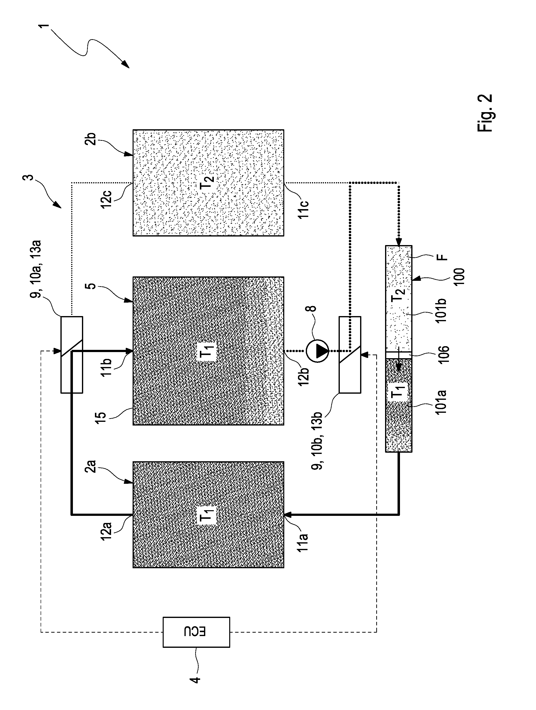
[0074] During the course of the thermal cycling, the thermochemical reactor 5 is now switched into a state at temperature T.sub.1 of the first heat reservoir 2a, whereby, initially, a temperature change is carried out in order to essentially heat the thermal masses of the reactor 5. In addition, both valve devices 10a, 10b are initially set into an operating state shown in FIG. 2 by the regulation/control device 4. In the operating state shown in FIG. 2, both valve devices 10a, 10b are configured in such a way that the heat transfer fluid F is transported from the first partial store 101a of the temporary heat store 100 into the first heat reservoir 2a. Furthermore, heat transfer fluid F is transported from the first heat reservoir 2a into the thermochemical reactor 5. Furthermore, heat transfer fluid F is transported from the thermochemical reactor 5 into the second partial store 101b.
[0075] In this operating state, the temperature-stratified heat transfer fluid F of the first partial store 101a of the temporary heat store 100 is pressed into the heat reservoir 2a, whereby the thermal reactor is consequently heated up to its temperature level T.sub.1. In turn, the second partial store 101b of the temporary heat store 100 is filled with a cool and increasingly warmer heat transfer fluid F coming from the thermochemical reactor 5.
[0076] As soon as the heat transfer fluid F temporarily stored in the first partial store 101a of the temporary heat store 100 has completely been taken from the temporary heat store 100, the separation element 106 is in the aforementioned first end position, which can be detected by the regulation/control device 4 by means of the first sensor element 110a.
[0077] Being triggered by the first sensor element 110a, both valve devices 10a, 10b are initially set into an operating state that is schematically shown in FIG. 3 by the regulation/control device 4.
[0078] In the operating state schematically shown in FIG. 3, the heat transfer fluid circuit 3 forms a second partial circuit 14b, in which the heat transfer fluid F circulates between the thermochemical reactor 5 and the first heat reservoir 2a. In this way, the heat transfer fluid F is transported from the first heat reservoir 2a to the thermochemical reactor. In this operating state, reaction heat is transferred from the first heat reservoir into the thermochemical reactor 5 at temperature level T.sub.1. In this operating state, the first second partial store 101b has a maximum volume and the first partial store 101a has a minimum volume, meaning the second partial store 101b of the temporary heat store 100 is filled with heat transfer fluid F, which comprises a temperature stratification increasing from left to right up to almost temperature T.sub.1. In contrast, the first partial store 101b is empty. The operating state shown in FIG. 3 can be referred to as "heat-supply mode".
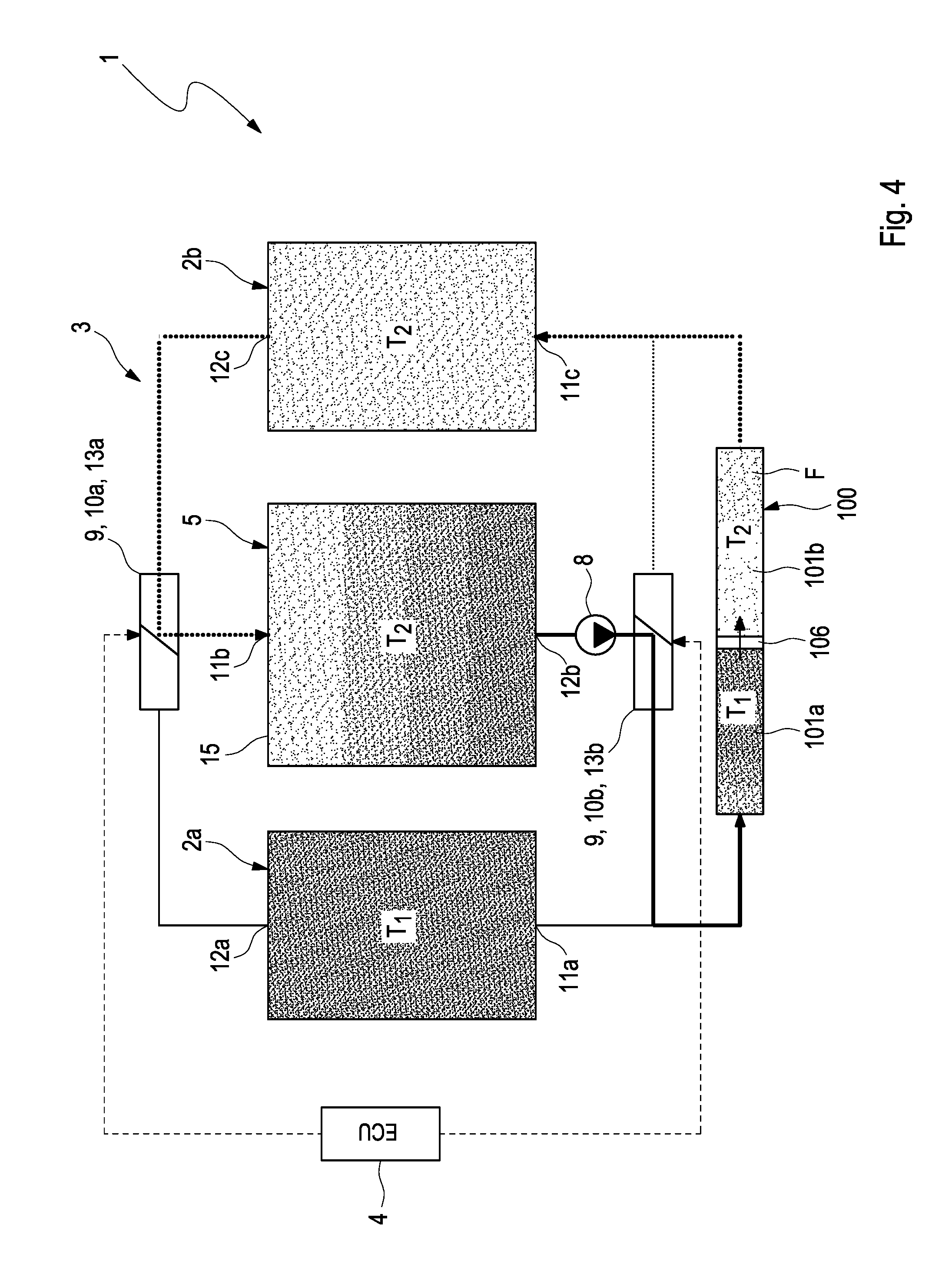
[0079] In order to instigate a "cooling mode", subsequently, both valve devices 10a, 10b can be set into an operating state shown in FIG. 4 by the regulation/control device 4. In the operating state shown in FIG. 4, both valve devices 10a, 10b are configured in such a way that the heat is transported from the second partial store 101b into the second heat reservoir 2b by means of the heat transfer fluid F. At the same time, by pressing out hot heat transfer fluid, sensitive heat is transported from the thermochemical reactor 5 into the first partial store 101a of the temporary heat store 100.
[0080] As soon as the heat transfer fluid F temporarily stored in the second partial store 101b of the temporary heat store 100 has completely been taken from the temporary heat store 100, the separation element 106 is in the aforementioned second end position, which can be detected by the regulation/control device 4 by means of the second sensor element 110b. In this state, the first partial store 101a is completely filled with the heat transfer fluid F (cf. FIG. 1) Being triggered by the sensor element 110b, the two valve devices 10a, 10b is switched into the operating state shown in FIG. 1 again by the regulation/control device 4 and a complete switching cycle of the thermochemical reactor 5 is completed.
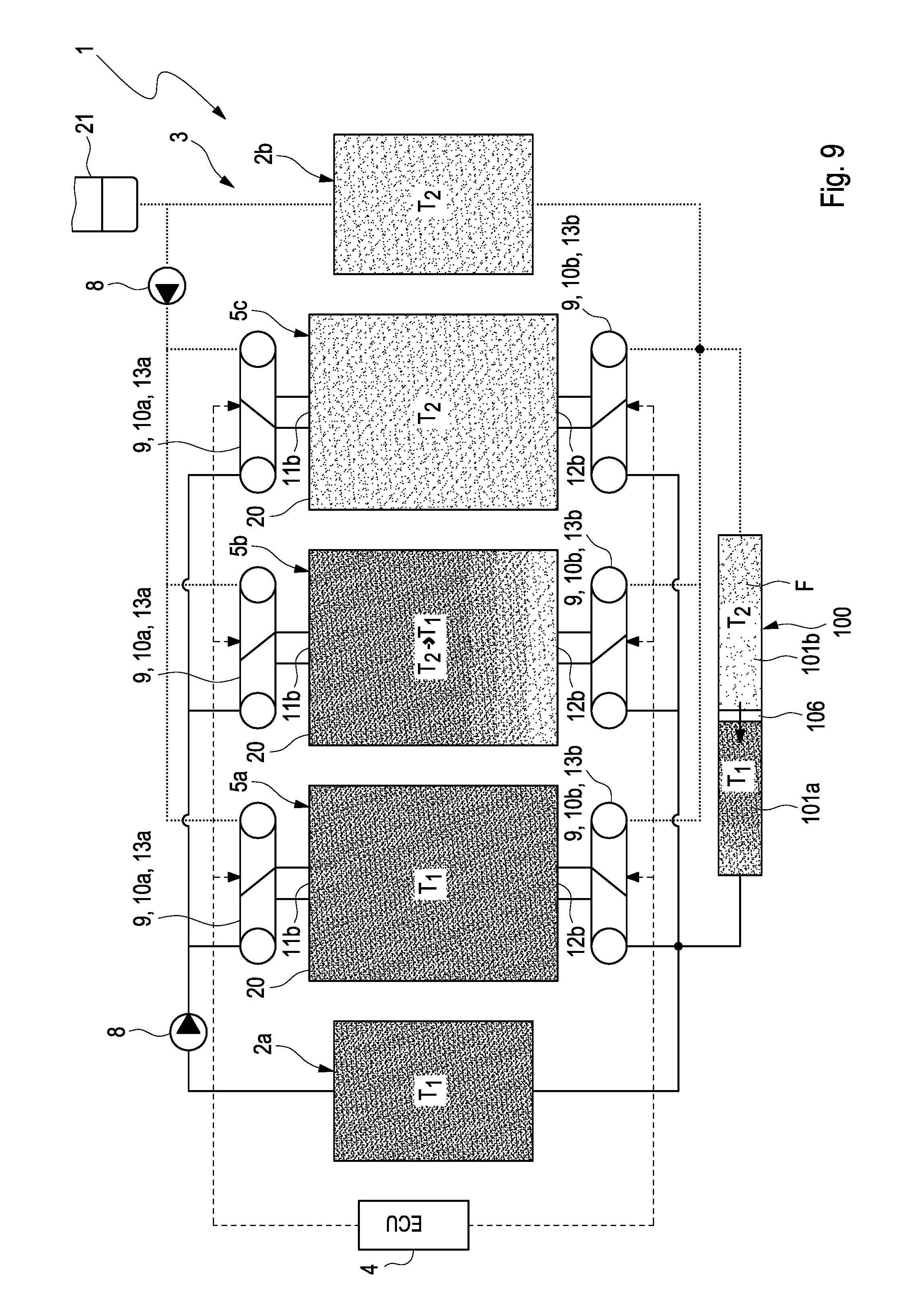
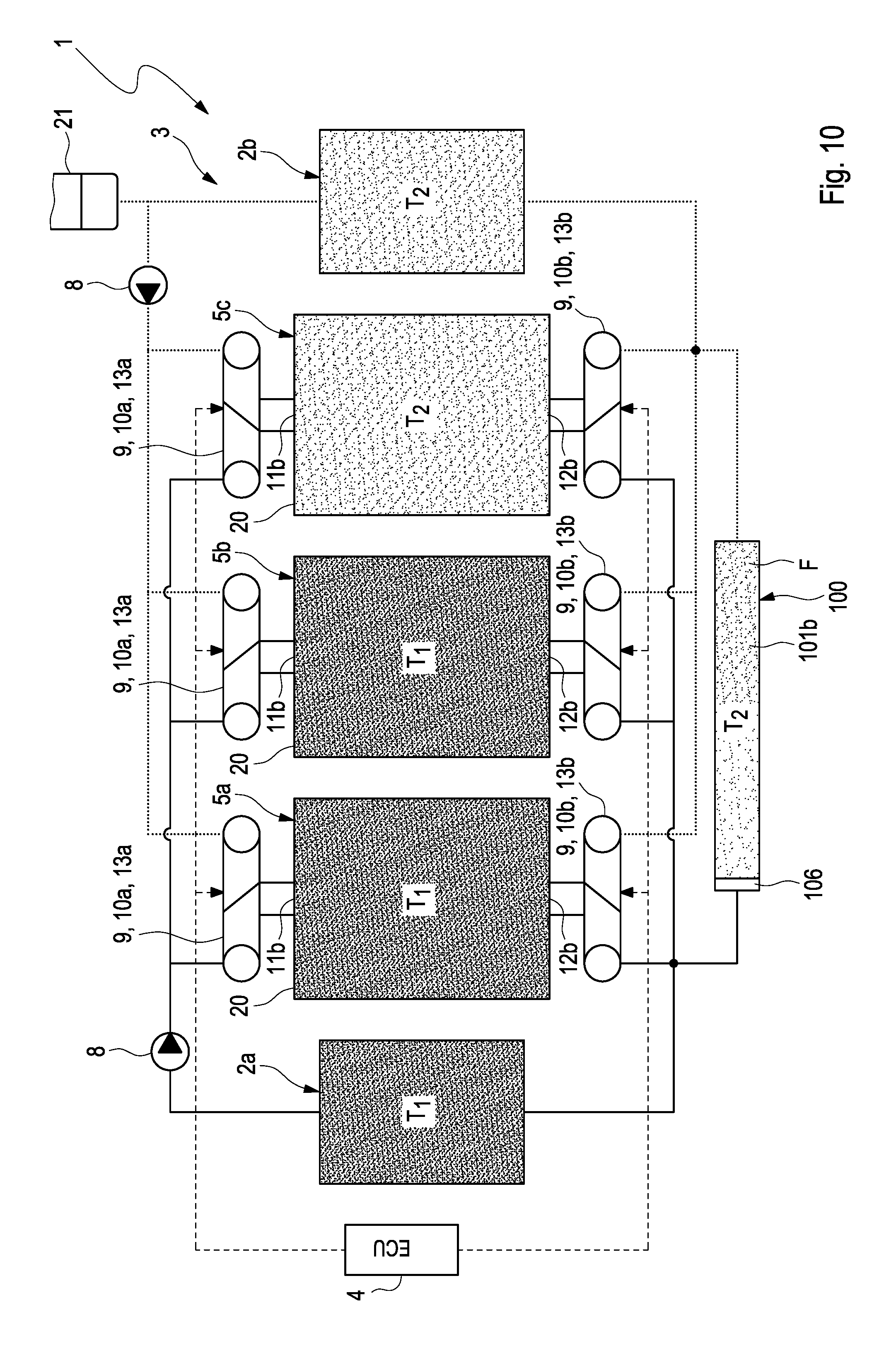
[0081] FIG. 8 shows a further embodiment of the arrangement of the FIGS. 1 to 4 where the arrangement 1 not only has a single thermochemical reactor, but three such thermochemical reactors 5a, 5b, 5c. Each thermochemical reactor 5a, 5b, 5c has its own housing 20a and a respective fluid inlet 11b as well as a fluid outlet 12b. As can be recognized in FIG. 8, the three thermochemical reactors 5a, 5b, 5c are fluidically connected to each other in parallel. In the present example, the reactors can be considered sorption reactors, which desorb a working material at a high temperature T.sub.1 and adsorb a working material at a lower temperature T.sub.2. They receive the desorption heat required for this from a high-temperature heat reservoir 2a serving as a heat source and emit adsorption heat to a low-temperature heat reservoir 2b acting as a heat sink in a time-delayed manner.
[0082] The valve system (9) comprises a first adjustable valve device 10a for each of the three thermochemical reactors 5a, 5b, 5c, by means of which the fluid inlet 11b of the respective thermochemical reactor 5a, 5b, 5c can be optionally connected to the first or the second heat reservoir 2a, 2b of the temperature T.sub.1 or T.sub.2. The valve system 9 furthermore comprises a second adjustable valve device 10b for each of the three thermochemical reactors 5, by means of which the fluid outlet 12b of the respective thermochemical reactor 5a, 5b, 5c can be optionally connected to the first or the second heat reservoir 2a, 2b. The temporary heat store 100 is installed in the arrangement 1 in such a way that the first partial store 101a fluidically communicates with the first heat reservoir 2a and the second partial store 101b fluidically communicates with the second heat reservoir 2b.
[0083] In the example in FIGS. 8 to 11, the three thermochemical reactors 5a, 5b, 5c are cycled analogously to the example in FIGS. 1 to 4, however, in a time-delayed manner to one another.
[0084] In FIG. 8, a stationary switching state of the first and second valve devices 10a, 10b is shown where the sorption reactor 5a at temperature T.sub.1 is desorbed by a heat supply from the first heat reservoir 2a while the second and the third sorption reactor 5b, 5c are in the adsorption process due to the heat dissipation to the second heat reservoir 2b at temperature T.sub.2. The first partial store 101a of the temporary heat store 100 is thereby filled with heat transfer fluid F at temperature T.sub.1, whereas the second partial store 101 is empty.
[0085] The subsequent switching position of the first and the second valve devices is shown in FIG. 9 where the second sorption reactor 5b is heated by means of the fact that the first valve device 10a associated with the second sorption reactor 5b is switched. As a result, the fluid inlet 11b of the second sorption reactor 5b is connected to the first heat reservoir 2a just like the first sorption reactor 5a. The third sorption reactor 5c remain connected to the second heat reservoir 2b on the inlet side. By means of this, the second sorption reactor 5b is heated and the cool heat transfer fluid, which is stratified ranging from being cool up to temperature T.sub.2, is pushed into the second partial store 101b of the temporary heat store 100. The heat transfer fluid stored in the first partial store 101a of the temporary heat store 100 stratified up to temperature T.sub.1 is pushed into the first heat reservoir 2a.
[0086] This unsteady temperature change process in the temporary heat store 100 has ended as soon as the heat transfer fluid F stratified up to temperature T.sub.1 in the temporary heat store 100 has been completely replaced by cooler heat transfer fluid stratified up to temperature T.sub.2 in the temporary heat store 100. Then, the second partial store 101b is completely filled and the first partial store 101a is empty. The illustration of FIG. 10 shows this scenario. Thereby, the sorption reactors 5a and 5b are in desorption mode and reactor 5c is in adsorption mode.
[0087] The next switching position of the first and the second valve devices 10a, 10b in accordance with FIG. 11 is used to cool the first sorption reactor 5a. For this, the first sorption reactor 5a is fluidically connected to the second heat reservoir 2b. In analogy to the heating process, the first sorption reactor 5a is cooled and, thereby the contained heat transfer fluid, which is initially hot at T.sub.1 is pressed into the first partial store 101a of the temporary heat store 100. At the same time, the heat transfer fluid F stored in the temporary heat store 100 is pressed out of the second partial store 101b of the temporary heat store 100. This subprocess also ends by switching the second valve device 10b associated with the first thermochemical store 5a as soon as the first partial store is completely filled with the heat transfer fluid F stratified up to temperature T.sub.1 and the second partial store 101b has been completely emptied.
[0088] This state corresponds to the state according to FIG. 8 with the difference that, now, the second sorption reactor 5b is in stand-alone stationary desorption mode. The partial cycles described in the above have also functioned to further activate the entire cycle around a sorption reactor. In order to complete a full cycle, 3*4=12 partial cycles are required until the initial state according to FIG. 8 is reached.
[0089] In the preceding explained example, the time-delayed switching of the first and the second valve devices 10a 10b take place in such a way that, at the same time, at least one of the sorption reactors 5a, 5b, 5c and a maximum of two of the available reactors 5a, 5b, 5c have the temperature level T.sub.1 of the first heat reservoir 2a. Thereby, it is possible to optimized the time allotments for the desorption and adsorption of each sorption reactor independent of the number of sorption reactors used.
[0090] Even in the case of the variant of the arrangement according to the invention with three thermochemical reactors described in the above based on FIGS. 8 to 11--in other variants, another number of thermochemical reactors can be selected--with the aid of the temporary heat store 100, the sensitive heat of the heat transfer fluid F contained in a thermochemical reactor to be thermally cycled can be recovered at high percentages. Depending on the volume design, this also applied to a part of the sensitive heat of stationary heat storage masses all the way to percentages of latent amounts of heat implemented therein, for example, sorption heat in the present case.
* * * * *
D00000
D00001
D00002
D00003
D00004
D00005
D00006
D00007
D00008
D00009
D00010
D00011
XML
uspto.report is an independent third-party trademark research tool that is not affiliated, endorsed, or sponsored by the United States Patent and Trademark Office (USPTO) or any other governmental organization. The information provided by uspto.report is based on publicly available data at the time of writing and is intended for informational purposes only.
While we strive to provide accurate and up-to-date information, we do not guarantee the accuracy, completeness, reliability, or suitability of the information displayed on this site. The use of this site is at your own risk. Any reliance you place on such information is therefore strictly at your own risk.
All official trademark data, including owner information, should be verified by visiting the official USPTO website at www.uspto.gov. This site is not intended to replace professional legal advice and should not be used as a substitute for consulting with a legal professional who is knowledgeable about trademark law.