External Gear Pump For A Waste Heat Recovery System
Bredenfeld; Guido ; et al.
U.S. patent application number 16/328790 was filed with the patent office on 2019-07-11 for external gear pump for a waste heat recovery system. The applicant listed for this patent is Robert Bosch GmbH. Invention is credited to Jakob Branczeisz, Guido Bredenfeld, Marc Laetzel, Matthias Riedle.
| Application Number | 20190211819 16/328790 |
| Document ID | / |
| Family ID | 59152868 |
| Filed Date | 2019-07-11 |


| United States Patent Application | 20190211819 |
| Kind Code | A1 |
| Bredenfeld; Guido ; et al. | July 11, 2019 |
EXTERNAL GEAR PUMP FOR A WASTE HEAT RECOVERY SYSTEM
Abstract
The invention relates to an external gear pump (1) having a pump housing (2). An inlet (2a), an outlet (2b), and a working chamber (6) are formed in the pump housing (2). A first gear (11), which is arranged on a first shaft (21), and a second gear (12), which is arranged on a second shaft (22), are arranged in the working chamber (6) in such a way that said first and second gears mesh with each other. Both gears (11, 12) have teeth having a tooth width (b). The first shaft (21) is radially supported in at least one plain bearing (61), and the second shaft (22) is radially supported in at least one further plain bearing (63). The plain bearing (61) has a bearing diameter (D63), and the further plain bearing (63) has a further bearing diameter (D63). During operation of the external gear pump (1), a delivery volume (V) of a working medium can be conveyed from the inlet (2a) to the outlet (2b). The two bearing diameters (D.sub.61, D.sub.63) are selected in such a way that the ratio V/(D.sub.61.sup.2*b) is less than 1.1 and the ratio V/(D.sub.63.sup.2*b) is less than 1.1.
| Inventors: | Bredenfeld; Guido; (Markgroeningen, DE) ; Branczeisz; Jakob; (Eberdingen, DE) ; Laetzel; Marc; (Stuttgart, DE) ; Riedle; Matthias; (Obersulm, DE) | ||||||||||
| Applicant: |
|
||||||||||
|---|---|---|---|---|---|---|---|---|---|---|---|
| Family ID: | 59152868 | ||||||||||
| Appl. No.: | 16/328790 | ||||||||||
| Filed: | June 20, 2017 | ||||||||||
| PCT Filed: | June 20, 2017 | ||||||||||
| PCT NO: | PCT/EP2017/065067 | ||||||||||
| 371 Date: | February 27, 2019 |
| Current U.S. Class: | 1/1 |
| Current CPC Class: | F04C 2/18 20130101; F04C 15/0088 20130101 |
| International Class: | F04C 2/18 20060101 F04C002/18 |
Foreign Application Data
| Date | Code | Application Number |
|---|---|---|
| Aug 29, 2016 | DE | 10 2016 216 159.8 |
Claims
1. An external gear pump (1) having a pump housing (2), wherein an inlet (2a), an outlet (2b), and a working chamber (6) are formed in the pump housing (2), wherein a first gear (11), which is arranged on a first shaft (21), and a second gear (12), which is arranged on a second shaft (22), are arranged in the working chamber (6) in such a way that said first and second gears mesh with each other, wherein both of the first and second gears (11, 12) have teeth having a tooth width (b), wherein the first shaft (21) is radially supported in at least one plain bearing (61), and wherein the second shaft (22) is radially supported in at least one further plain bearing (63), wherein the one plain bearing (61) has a first bearing diameter (D.sub.61), and wherein the further plain bearing (63) has a further bearing diameter (D.sub.63), wherein, during operation of the external gear pump (1), a delivery volume (V) of a working medium can be conveyed from the inlet (2a) to the outlet (2b), characterized in that the ratio V/(D.sub.61.sup.2*b) is <1.1 and the ratio V/(D.sub.63.sup.2*b) is <1.1.
2. The external gear pump (1) as claimed in claim 1, characterized in that the ratio V/(D.sub.61.sup.2*b) is >0.5 and the ratio V/(D.sub.63.sup.2*b) is >0.5.
3. The external gear pump (1) as claimed in claim 1, characterized in that the first bearing diameter D.sub.61 and the further bearing diameter D.sub.63 are equal.
4. The external gear pump (1) as claimed in claim 1, characterized in that the first and second shafts (21, 22) are each radially supported in two plain bearings (61, 62, 63, 64), wherein, for each bearing diameter (D.sub.61, D.sub.62, D.sub.63, D.sub.64): V/(D.sup.2*b)<1.1, where D={D.sub.61; D.sub.62; D.sub.63; D.sub.64}.
5. The external gear pump (1) as claimed in claim 4, characterized in that furthermore: D.sub.61=D.sub.62=D.sub.63=D.sub.64.
6. An external gear pump (1) having a pump housing (2), wherein an inlet (2a), an outlet (2b), and a working chamber (6) are formed in the pump housing (2), wherein a first gear (11), which is arranged on a first shaft (21), and a second gear (12), which is arranged on a second shaft (22), are arranged in the working chamber (6) in such a way that said first and second gears mesh with each other, wherein the first gear (11) has a first tip diameter (DK.sub.11) and the second gear (12) has a second tip diameter (DK.sub.12), wherein the first shaft (21) is radially supported in at least one plain bearing (61) and wherein the second shaft (22) is radially supported in at least one further plain bearing (63), wherein the first and second shafts (21, 22) are arranged parallel with a center distance (a) with respect to each other, wherein the one plain bearing (61) has a first bearing diameter (D.sub.61) and wherein the further plain bearing (63) has a further bearing diameter (D.sub.63), characterized in that the ratio (DK.sub.11*a)/D.sub.61.sup.2 is <2.5 and the ratio (DK.sub.12*a)/D.sub.63.sup.2 is <2.5.
7. The external gear pump (1) as claimed in claim 6, characterized in that the ratio (DK.sub.11*a)/D.sub.61.sup.2 is >1.5 and in that the ratio (DK.sub.12*a)/D.sub.63.sup.2 is >1.5.
8. The external gear pump (1) as claimed in claim 6, characterized in that the first bearing diameter D.sub.61 and the further bearing diameter D.sub.63 are equal.
9. The external gear pump (1) as claimed in claim 6, characterized in that the first and second shafts (21, 22) are each radially supported in two plain bearings (61, 62, 63, 64), wherein, for each bearing diameter (D.sub.61, D.sub.62, D.sub.63, D.sub.64): (DK*a)/D.sup.2 is <2.5 where DK={DK.sub.11; DK.sub.12} and where D={D.sub.61; D.sub.62; D.sub.63; D.sub.64}.
10. The external gear pump (1) as claimed in claim 9, characterized in that furthermore: D.sub.61=D.sub.62=D.sub.63=D.sub.64.
11. A heat recovery system having a circuit that carries a working medium, wherein the circuit comprises a feed fluid pump, an evaporator, an expansion machine (104) and a condenser in the flow direction of the working medium, characterized in that the feed fluid pump is embodied as an external gear pump (1) as claimed in claim 1.
12. The external gear pump (1) as claimed in claim 1, characterized in that the ratio V/(D.sub.61.sup.2*b) is >1.0 and the ratio V/(D.sub.63.sup.2*b) is >1.0.
13. The external gear pump (1) as claimed in claim 6, characterized in that the ratio (DK.sub.11*a)/D.sub.61.sup.2 is >2.0 and the ratio (DK.sub.12*a)/D.sub.63.sup.2 is >2.0.
Description
BACKGROUND OF THE INVENTION
[0001] The present invention relates to an external gear pump, in particular one embodied as a feed fluid pump of a waste heat recovery system of an internal combustion engine.
[0002] There are many instances of fluid delivery pumps in the prior art, e.g. in the form of external gear pumps from German Laid-Open Application DE 10 2009 045 030 A1.
[0003] Moreover, the arrangement of feed fluid pumps within a waste heat recovery system of an internal combustion engine is also known in principle, e.g. from German Laid-Open Application DE 10 2013 205 648 A1. However, the known documents leave open the question of how the feed fluid pump can be operated with the longest possible service life, even with aggressive working media in heat recovery systems, which have a very low viscosity.
SUMMARY OF THE INVENTION
[0004] In contrast, the external gear pump according to the invention has the advantage that it can be used for low-viscosity working media that are poor lubricants and can form a hydrodynamic lubricating film in the plain bearings, even for such working media. The bearing service life is thereby significantly increased.
[0005] For this purpose, the external gear pump has a pump housing. An inlet, an outlet, and a working chamber are formed in the pump housing. A first gear, which is arranged on a first shaft, and a second gear, which is arranged on a second shaft, are arranged in the working chamber in such a way that said first and second gears mesh with each other. Both gears have teeth having a tooth width b. The first shaft is radially supported in at least one plain bearing, and the second shaft is radially supported in at least one further plain bearing. The plain bearing has a bearing diameter D.sub.61, and the further plain bearing has a further bearing diameter D.sub.63. During operation of the external gear pump 1, a delivery volume V of a working medium can be conveyed from the inlet to the outlet. The two bearing diameters D.sub.61, D.sub.63 are designed in such a way that the ratio V/(D.sub.61.sup.2*b) is <1.1 and that the ratio V/(D.sub.63.sup.2*b) is <1.1.
[0006] It is furthermore advantageous if the ratio V/(D.sub.61.sup.2*b) is >0.5, in particular greater than 1.0. Similarly also, the ratio V/(D.sub.63.sup.2*b) is >0.5, in particular greater than 1.0. These two ratios should therefore not be arbitrarily small since the delivery volume V approaching zero and dimensions approaching infinity make no sense for the external gear pump according to the invention.
[0007] The design of the external gear pump runs contrary to the typical manner of proceeding of a person skilled in the art, who would wish to achieve a delivery volume V which is as high as possible combined with dimensions of the components of the external gear pump which are as small as possible.
[0008] The plain bearings can be designed as bearing bores in the pump housing, or in a double bearing seat or bearing bush arranged therein, for example. The delivery volume V is the volume of the working medium delivered to the outlet at typical operating points.
[0009] Owing to the atypical large bearing diameters that are used as a result for the plain bearings of the external gear pump, low-viscosity working media that are poor lubricants can be delivered without having to hermetically seal the plain bearings relative to the working chamber. Even working media with a kinematic viscosity<<2 mm.sup.2/s can be delivered in this way. The contact surfaces between the shafts and the plain bearings are increased by this design, and therefore a hydrodynamic sliding film can form in the plain bearings during operation. The wear in the plain bearings is thereby significantly reduced and, accordingly, the service life of the plain bearings and hence also of the entire external gear pump is increased. In the best case, it is even possible to dispense with expensive, particularly wear-resistant materials for the plain bearings.
[0010] In preferred developments, the two bearing diameters of the plain bearing and of the further plain bearing are equal. As a result, the two plain bearings can be of unitary design. It is furthermore also possible to choose gears of the same size, thus optimizing the efficiency of the external gear pump.
[0011] In advantageous embodiments, the two shafts are each radially supported in two plain bearings, advantageously on both sides of the gears. The above design formula then applies to all four plain bearings, i.e. V/(D.sup.2*b)<1.1, where D={D.sub.61; D.sub.62; D.sub.63; D.sub.64}, wherein D.sub.61, D.sub.62, D.sub.63, D.sub.64 are the four bearing diameters. All four bearing diameters are then also preferably equal: D.sub.61=D.sub.62=D.sub.63=D.sub.64.
[0012] Alternative design concepts and also design concepts that can be combined with the above designs are described below. Here, the following design concepts are independent of the delivery volume V.
[0013] For this purpose, the external gear pump has a pump housing. An inlet, an outlet, and a working chamber are formed in the pump housing. A first gear, which is arranged on a first shaft, and a second gear, which is arranged on a second shaft, are arranged in the working chamber in such a way that said first and second gears mesh with each other. The first gear has a first tip diameter DK.sub.11 and the second gear has a second tip diameter DK.sub.12, wherein preferably both tip diameters DK.sub.11, DK.sub.12 are equal. The first shaft is radially supported in at least one plain bearing and the second shaft is radially supported in at least one further plain bearing. The two shafts are arranged parallel with a center distance a with respect to each other. The plain bearing has a bearing diameter D.sub.61 and the further plain bearing has a further bearing diameter D.sub.63. The two bearing diameters D.sub.61, D.sub.63 are designed in such a way that the ratio (DK.sub.11*a)/D.sub.61.sup.2 is <2.5 and that the ratio (DK.sub.12*a)/D.sub.63.sup.2 is <2.5.
[0014] The ratio is furthermore advantageously (DK.sub.11*a)/D.sub.61.sup.2>1.5--in particular greater than 2.0. Similarly also, the ratio (DK.sub.12*a)/D.sub.63.sup.2 is >1.5--in particular greater than 2.0. These two ratios should therefore not become arbitrarily small since the tip diameters and the center distance approaching zero and bearing diameters approaching infinity make no sense for the external gear pump according to the invention.
[0015] The design of the external gear pump runs contrary to the typical manner of proceeding of a person skilled in the art, who would always wish to make the bearing diameters as small as possible.
[0016] In these embodiments too, the plain bearings can be designed as bearing bores in the pump housing, or in a double bearing seat or bearing bush arranged therein, for example.
[0017] Owing to the atypical large bearing diameters that are used by this design concept for the plain bearings of the external gear pump, low-viscosity working media that are poor lubricants can be delivered without having to hermetically seal the plain bearings relative to the working chamber. The same advantages as those already described above apply.
[0018] There are likewise also the same developments of the invention as above: the radial support for the two shafts by two plain bearings in each case and the use of equal bearing diameters for all the plain bearings, wherein each bearing diameter should be dimensioned in accordance with the design concept.
[0019] External gear pumps are very well-suited to use in waste heat recovery systems of internal combustion engines. Waste heat recovery systems of this kind often use low-viscosity working media that are poor lubricants. The external gear pump according to the invention can therefore be used very advantageously in a waste heat recovery system. The waste heat recovery system has a circuit that carries a working medium, wherein the circuit comprises a feed fluid pump, an evaporator, an expansion machine and a condenser in the flow direction of the working medium. Here, the feed fluid pump is embodied as an external gear pump having the features described above.
BRIEF DESCRIPTION OF THE DRAWINGS
[0020] Illustrative embodiments of the invention are described in greater detail below with reference to the attached drawings, in which:
[0021] FIG. 1 shows an external gear pump from the prior art in an exploded illustration, wherein only the essential regions are illustrated,
[0022] FIG. 2 shows a schematic sectional illustration through an external gear pump from the prior art,
[0023] FIG. 3 shows an external gear pump in longitudinal section, wherein only the essential regions are illustrated.
DETAILED DESCRIPTION
[0024] An external gear pump 1 from the prior art is shown in an exploded illustration in FIG. 1. The external gear pump 1 comprises a pump housing 2, a cover 3 and a bottom flange 4. The cover 3 and the bottom flange 4 are clamped to one another by four screws 5 with the pump housing 2 in between. The pump housing 2, the cover 3 and the bottom flange 4 delimit a working chamber 6.
[0025] A first gear 11 and a second gear 12 are arranged in the working chamber 6 in such a way that said first and second gears mesh with each other. In this case, both gears 11, 12 have a certain number of teeth, each having a tooth width or gear width b. The first gear 11 is secured on a first shaft 21, and the second gear 12 is secured on a second shaft 22 parallel to the first shaft 21. Here, the first shaft 21 serves as a drive shaft and is connected to a drive (not illustrated), e.g. a crankshaft of an internal combustion engine. For this purpose, the first shaft 21 projects through the bottom flange 4.
[0026] The two shafts 21, 22 each project through the gear 11, 12 associated therewith and are connected firmly thereto, in each case by a press fit, for example. The shafts 21, 22 are supported on both sides of the gears 11, 12. Support is provided by two double bearing seats 30, 40, wherein the double bearing seats 30, 40 are arranged in the working chamber 6: one double bearing seat 30 is arranged adjacent to the bottom flange 4, and a further double bearing seat 40 is arranged adjacent to the cover 3. Two bearing bushes 9 are press-fitted in each of the two double bearing seats 30, 40. The bearing bushes 9 of the double bearing seat 30 support the two shafts 21, 22 on the drive side, and the bearing bushes 9 of the further double bearing seat 40 support them on the opposite side of the gears 11, 12. The bearing bushes 9 thus form plain bearings for the two shafts 21, 22. As an alternative, the two bearing bushes 9 can also be embodied integrally with the double bearing seat 30. The same also applies to the further double bearing seat 40.
[0027] The four bearing bushes 9 each have a radial bearing function and each form a plain bearing with the shaft 21, 22 associated therewith. The axial bearing function is achieved by means of the two double bearing seats 30, 40: for this purpose, double bearing seat 30 has a stop surface 31 on an end face, and the further double bearing seat 40 has a further stop surface 42 on an end face. Both stop surfaces 31, 42 interact with both gears 11, 12. Stop surface 31 supports both gears 11, 12 in the axial direction oriented toward the bottom flange 4; the further stop surface 42 supports both gears 11, 12 in the axial direction oriented toward the cover 3.
[0028] To seal off the working chamber 6 with respect to the surroundings, two seals are arranged on the pump housing 2: a seal 28 between the pump housing 2 and the bottom flange 4 and a further seal 29 between the pump housing 2 and the cover 3. Both seals 28, 29 extend approximately in a ring shape over the circumference of the pump housing 28, 29 and are usually arranged in corresponding grooves.
[0029] An axial field seal 18 is furthermore arranged between double bearing seat 30 and the bottom flange 4, and a further axial field seal 19 is arranged between the further double bearing seat 40 and the cover 3. On the one hand, the two axial field seals 18, 19 provide axial support for the two double bearing seats 30, 40 within the pump housing 2. On the other hand, the end faces or rear sides of the two double bearing seats 30, 40 are thereby subjected either to the pressure level of the pressure zone or to the pressure level of the suction zone, depending on the angle of rotation.
[0030] FIG. 2 shows the principle of action of the external gear pump 1 known from the prior art in a schematic sectional illustration. An inlet 2a and an outlet 2b, which open into the working chamber 6 on opposite sides, are formed in the pump housing 2. A delivery volume V of the working medium is thus conveyed from the inlet 2a to the outlet 2b on the housing wall of the pump housing 2 between the teeth of the two gears 11, 12. Here, the delivery volume V corresponds to the volume delivered in rated operation of the external gear pump 1, i.e. to the volume delivered at significant operating points. In respect of the tooth width b of the two gears 11, 12, a specific delivery volume V.sub.spec=V/b is thus obtained.
[0031] As a result, the suction zone of the external gear pump 1 with a low first pressure level--e.g. atmospheric pressure--is formed in the region of the inlet 2a, and the pressure zone of the external gear pump 1 with a higher, second pressure level--e.g. 40 bar--is formed in the region of the outlet 2b. Here, the second pressure level of the pressure zone depends on the following flow topology, e.g. on a restriction.
[0032] The tip diameter DK.sub.11 of the first gear 11 and the tip diameter DK.sub.12 of the second gear 12 are furthermore illustrated, as is the center distance a between the two shafts 21, 22. Preferably, the two tip diameters DK.sub.11, DK.sub.12 are equal and the two gears 11, 12 have the same number of teeth.
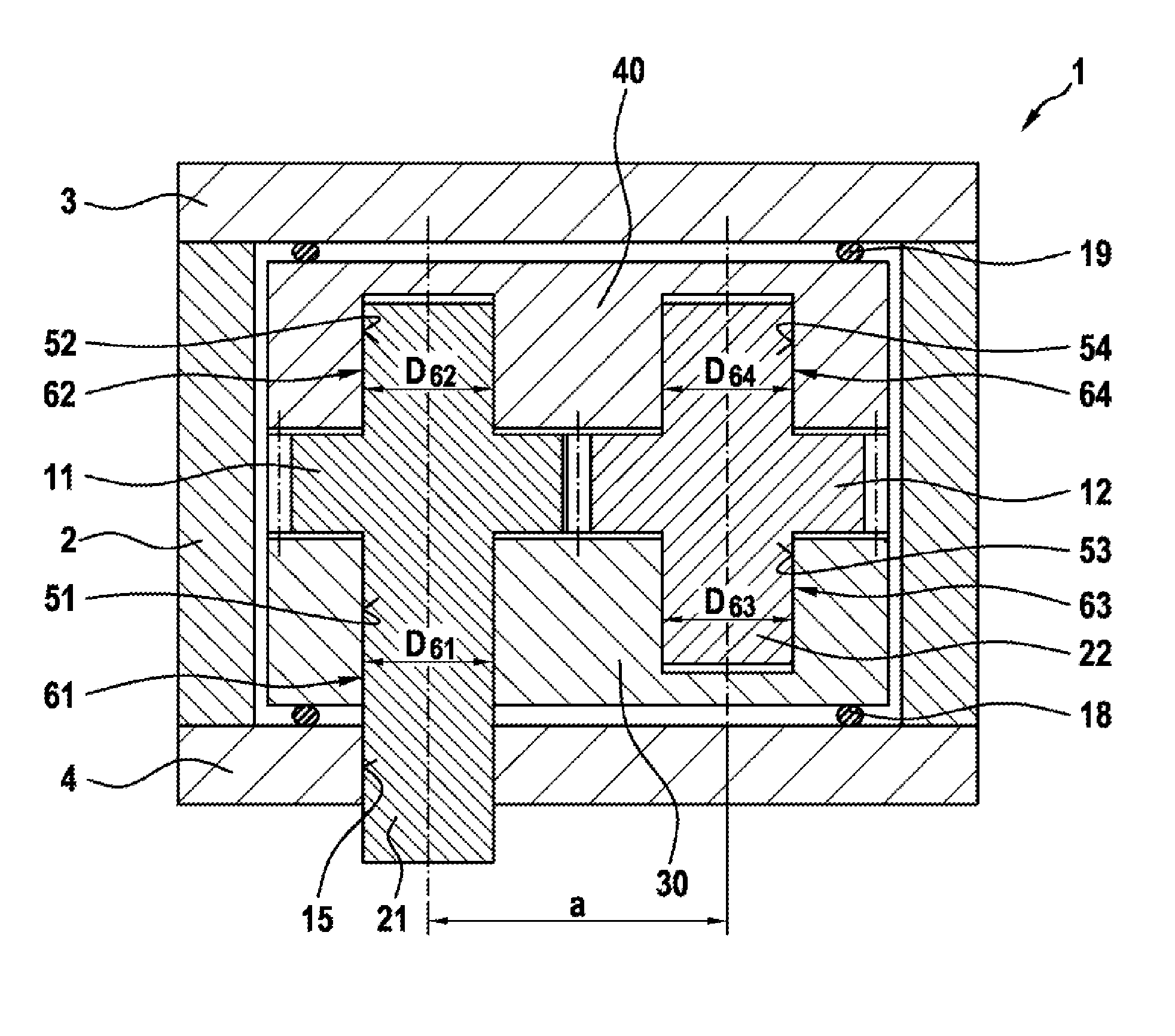
[0033] FIG. 3 shows a cross section of an external gear pump 1 according to the invention in the region through the longitudinal axes of the two shafts 21, 22, which are arranged parallel to one another at a center distance a. According to the invention, the diameters of the plain bearings 61, 62, 63, 64 of the two shafts 21, 22 are made significantly larger than in the case of conventional external gear pumps. As a result, the external gear pump 1 according to the invention is suitable for low-viscosity (e.g. for viscosities<<2 mm.sup.2/s) and working media that are poor lubricants. The external gear pump 1 according to the invention is therefore particularly well-suited for use in waste heat recovery systems of internal combustion engines.
[0034] The gear pair, i.e. the two gears 11, 12, are supported by means of plain bearings 61, 62, 63, 64. In the embodiment in FIG. 3, support is provided in two two-part double bearing seats 30, 40. However, the two double bearing seats 30, 40 can also be of integral construction. As an option, it is also possible to use bearing bushes, as depicted in FIG. 1. In this case, double bearing seat 30 and the further double bearing seat 40 can also be of different construction, as before.
[0035] Double bearing seat 30 is supported via the axial field seal 18 on the bottom flange 4, and the further double bearing seat 40 is supported via the further axial field seal 19 on the cover 3. Both double bearing seats 30, 40 are thus supported in the pump housing 2 via the two axial field seals 18, 19 and the shafts 21, 22 arranged therebetween and via gears 11, 12.
[0036] A through-drive shaft opening 15 is formed in the bottom flange 4. As a result, the drive shaft of the external gear pump 1, in this case the first shaft 21, can be passed out of the pump housing 2 and coupled to a drive, e.g. a coupling or a belt.
[0037] Four bearing bores 51, 52, 53, 54 are formed in the double bearing seats 30, 40, with the result that the first shaft 21 is supported by means of the first bearing bore 51 and by means of the second bearing bore 52, and with the result that the second shaft 22 is supported by means of the third bearing bore 53 and by means of the fourth bearing bore 54. Three bearing bores 52, 53, 54 are embodied as blind bores, while the first bearing bore 51 is embodied as a through bore, thus enabling the first shaft 21, which is embodied as a drive shaft, to be passed out of double bearing seat 30.
[0038] The four bearing bores 51, 52, 53, 54 each form a plain bearing 61, 62, 63, 64 for the shafts 21, 22. The first shaft 21 is supported in two plain bearings 61, 62, wherein the two plain bearings 61, 62 are arranged on opposite sides of the first gear 11 when viewed in the axial direction. The second shaft 22 is supported in two further plain bearings 63, 64, wherein the two further plain bearings 63, 64 are arranged on opposite sides of the second gear 12 when viewed in the axial direction.
[0039] In alternative embodiments, the external gear pump 1 has just one plain bearing for each shaft 21, 22. That is to say, for example, the first shaft 21 is then radially supported only by plain bearing 61, and the second shaft 22 is radially supported only by the further plain bearing 63 within the pump housing 2.
[0040] According to the invention, the plain bearings 61, 62, 63, 64, unlike the conventional designs, are provided with particularly large bearing diameters D.sub.61, D.sub.62, D.sub.63, D.sub.64. The individual bearing diameters D.sub.61, D.sub.62, D.sub.63, D.sub.64 are configured in such a way that: [0041] in respect of the specific delivery volume V.sub.spec: V.sub.spec/D.sup.2<1.1 [0042] in respect of the delivery volume V: V/(D.sup.2b)<1.1 wherein D={D.sub.61; D.sub.62; D.sub.63; D.sub.64}.
[0043] Here, it is advantageous if D.sub.61=D.sub.62=D.sub.63=D.sub.64.
[0044] As an alternative or in addition, the bearing diameters D.sub.61, D.sub.62, D.sub.63, D.sub.64 of the plain bearings 61, 62, 63, 64 should be configured in relation to the tip diameter DK.sub.11, DK.sub.12 of the two gears 11, 12 and in relation to the center distance a of the two shafts 21, 22 relative to one another. Here, the following should apply: (DK*a)/D.sup.2<2.5, where DK={DK.sub.11; DK.sub.12} and D={D.sub.61; D.sub.62; D.sub.63; D.sub.64}.
[0045] The peripheral speed of the cylindrical contact surfaces of the shafts 21, 22 in the plain bearings 61, 62, 63, 64 is thereby increased to such an extent that the radial sliding support with a given low-viscosity working medium and a given, relatively low delivery volume V of the external gear pump 1 functions in the hydrodynamic mode, that is to say a lubricating film can build up between the shafts 21, 22 and the plain bearings 61, 62, 63, 64. For this purpose, the aim is to make the bearing diameter D.sub.61, D.sub.62, D.sub.63, D.sub.64 of the plain bearings 61, 62, 63, 64 as large as possible, and therefore a tooth system of the two gears 11, 12 is chosen which, on the one hand, still rolls cleanly in mechanical terms and allows adequate hydraulic seals with respect to the pump housing 2, the cover 3 and the bottom flange 4 without producing an excessive delivery volume V, wherein the delivery volume V should be suitable, in particular, for a waste heat recovery system.
[0046] The object of designing the external gear pump 1 in such a way that the sliding speed between the shaft 21, 22 and the plain bearings 61, 62, 63, 64 is very greatly increased does not arise in the project planning for a conventional external gear pump corresponding to the prior art for the usual higher-viscosity working media. In that case, it is namely possible, for a given delivery volume, to optimize as regards a compact installation space, i.e. in the direction of plain bearings which are as small as possible. A hydrodynamic lubricating film would nevertheless be established in the contact locations of the plain bearings.
[0047] The invention is defined in such a way that a ratio of the specific delivery volume V.sub.spec of the delivery tooth system [mm.sup.3 delivery volume V per millimeter of gear width b] in relation to the square of the bearing diameter D of the plain bearings is less than 1.1. Pumps according to the prior art generally have a ratio of 2 and above in this respect. Alternatively, another ratio of the product of the tip diameter DK and the center distance a divided by the square of the bearing diameter D is less than 2.5. Pumps according to the prior art generally have a further ratio of this kind of 3 and above.
[0048] In particularly advantageous embodiments, the external gear pump 1 according to the invention is arranged in a waste heat recovery system of an internal combustion engine. The internal combustion engine is supplied with oxygen via an air inlet; the exhaust gas expelled after the combustion process is discharged from the internal combustion engine through an exhaust line.
[0049] The waste heat recovery system has a circuit that carries a working medium, which comprises a feed fluid pump, an evaporator, an expansion machine and a condenser in the flow direction of the working medium. The working medium can be fed into the circuit from a collecting tank and a valve unit via a branch line as required. As an alternative here, the collecting tank can also be incorporated into the circuit.
[0050] The evaporator is connected to the exhaust line of the internal combustion engine and therefore uses the heat energy of the exhaust gas of the internal combustion engine.
[0051] Liquid working medium is fed into the evaporator by the feed fluid pump, optionally from the collecting tank, and is evaporated there by the heat energy of the exhaust gas of the internal combustion engine. The evaporated working medium is then expanded in the expansion machine, releasing mechanical energy, e.g. to a generator (not illustrated) or a transmission (not illustrated). The working medium is then condensed again in the condenser and returned to the collecting tank or fed to the feed fluid pump.
[0052] Here, the feed fluid pump of the waste heat recovery system is an external gear pump 1 according to one of the above embodiments.
* * * * *
D00000
D00001
D00002
D00003
XML
uspto.report is an independent third-party trademark research tool that is not affiliated, endorsed, or sponsored by the United States Patent and Trademark Office (USPTO) or any other governmental organization. The information provided by uspto.report is based on publicly available data at the time of writing and is intended for informational purposes only.
While we strive to provide accurate and up-to-date information, we do not guarantee the accuracy, completeness, reliability, or suitability of the information displayed on this site. The use of this site is at your own risk. Any reliance you place on such information is therefore strictly at your own risk.
All official trademark data, including owner information, should be verified by visiting the official USPTO website at www.uspto.gov. This site is not intended to replace professional legal advice and should not be used as a substitute for consulting with a legal professional who is knowledgeable about trademark law.