Corrosion Resistant Sucker Rod
MARTINEZ; Oscar E. ; et al.
U.S. patent application number 16/074594 was filed with the patent office on 2019-07-11 for corrosion resistant sucker rod. The applicant listed for this patent is WEATHERFORD TECHNOLOGY HOLDINGS, LLC. Invention is credited to Robert P. BADRAK, Oscar E. MARTINEZ, John STACHOWIAK, Jr..
| Application Number | 20190211630 16/074594 |
| Document ID | / |
| Family ID | 65271182 |
| Filed Date | 2019-07-11 |
| United States Patent Application | 20190211630 |
| Kind Code | A1 |
| MARTINEZ; Oscar E. ; et al. | July 11, 2019 |
CORROSION RESISTANT SUCKER ROD
Abstract
A sucker rod for use in a subterranean well and a method of producing same, in which the method can include air quenching a martensitic stainless steel material of the sucker rod. An artificial lift system and a method of flowing a fluid from a well, in which the method can include connecting multiple air quenched and tempered sucker rods in a rod string connected to a downhole pump, and operating the downhole pump, thereby flowing the fluid from the well. A sucker rod can include a stainless steel sucker rod composition in which a carbon content is restricted to the range of 0.08% to 0.15%, and in which the sucker rod composition includes up to 0.20% vanadium content, up to 0.10% niobium content, up to 0.05% titanium content, up to 0.99% nickel content and/or up to 1.0% molybdenum content.
| Inventors: | MARTINEZ; Oscar E.; (Houston, TX) ; STACHOWIAK, Jr.; John; (Houston, TX) ; BADRAK; Robert P.; (Sugar Land, TX) | ||||||||||
| Applicant: |
|
||||||||||
|---|---|---|---|---|---|---|---|---|---|---|---|
| Family ID: | 65271182 | ||||||||||
| Appl. No.: | 16/074594 | ||||||||||
| Filed: | August 11, 2017 | ||||||||||
| PCT Filed: | August 11, 2017 | ||||||||||
| PCT NO: | PCT/US2017/046597 | ||||||||||
| 371 Date: | August 1, 2018 |
| Current U.S. Class: | 1/1 |
| Current CPC Class: | E21B 17/04 20130101; E21B 43/126 20130101; C22C 38/18 20130101; C22C 38/02 20130101; E21B 43/127 20130101; C21D 9/00 20130101; C22C 38/26 20130101; C21D 2211/008 20130101; C21D 6/002 20130101; E21B 19/16 20130101; C21D 9/14 20130101; C22C 38/22 20130101; C21D 9/0075 20130101; E21B 17/10 20130101; E21B 43/12 20130101; C22C 38/04 20130101; C22C 38/24 20130101; E21B 34/14 20130101; F16L 9/02 20130101; E21B 17/00 20130101; C21D 1/18 20130101 |
| International Class: | E21B 17/00 20060101 E21B017/00; C21D 9/00 20060101 C21D009/00; C21D 1/18 20060101 C21D001/18; E21B 19/16 20060101 E21B019/16; E21B 43/12 20060101 E21B043/12 |
Claims
1. A method of producing a sucker rod for use in a subterranean well, the method comprising: maintaining a temperature of a martensitic stainless steel material of the sucker rod at an elevated temperature; and then air quenching the material.
2. The method of claim 1, in which the elevated temperature is approximately 982.degree. C.+/-8.degree. C.
3. The method of claim 2, in which the elevated temperature is maintained for approximately 30 minutes.
4. The method of claim 1, further comprising tempering the material after the air quenching.
5. The method of claim 4, in which the tempering comprises maintaining the temperature of the material at a tempering temperature of approximately 649.degree. C.+/-14.degree. C.
6. The method of claim 5, in which the tempering further comprises maintaining the material at the tempering temperature for a duration of approximately 45 minutes to approximately one hour.
7. The method of claim 1, further comprising forging the material.
8. The method of claim 7, in which the forging comprises elevating the temperature of the material to approximately 1288.degree. C.+/-28.degree. C. prior to deforming the material.
9. The method of claim 7, in which the forging comprises configuring the sucker rod for forming on the material at least one of the group consisting of wrench flats and threads.
10. The method of claim 1, further comprising restricting a carbon content of the material to the range of 0.08% to 0.15%.
11. The method of claim 10, in which the material comprises at least one of the group consisting of: up to 0.20% vanadium content, up to 0.10% niobium content, up to 0.05% titanium content, up to 0.99% nickel content and up to 1.0% molybdenum content.
12. A sucker rod produced by the method of claim 1.
13. A sucker rod for use in a subterranean well, the sucker rod comprising: a stainless steel sucker rod composition in which a carbon content is restricted to the range of 0.08% to 0.15%, and in which the sucker rod composition comprises at least one of the group consisting of: up to 0.20% vanadium content, up to 0.10% niobium content, up to 0.05% titanium content, up to 0.99% nickel content and up to 1.0% molybdenum content.
14. The sucker rod of claim 13, in which the sucker rod composition comprises about 0.05% vanadium content, about 0.5% nickel content, and about 0.20% molybdenum content.
15. The sucker rod of claim 13, in which the sucker rod composition comprises about 0.05% vanadium content, about 0.95% nickel content, and about 0.50% molybdenum content.
16. The sucker rod of claim 13, in which the sucker rod composition comprises about 0.04% niobium content, about 0.5% nickel content, and about 0.20% molybdenum content.
17. The sucker rod of claim 13, in which the sucker rod composition comprises about 0.015% titanium content, about 0.5% nickel content, and about 0.20% molybdenum content.
18. The sucker rod of claim 13, in which a chromium content of the sucker rod composition is 11.5 to 13.0%.
19. A method of flowing a fluid from a subterranean well, the method comprising: producing multiple sucker rods, the producing comprising maintaining a temperature of a martensitic stainless steel material of the sucker rods at approximately an elevated temperature, and then air quenching the material; connecting the sucker rods in a rod string, the connecting including connecting the rod string to a downhole pump; and operating the downhole pump, thereby flowing the fluid from the well.
20. The method of claim 19, in which the elevated temperature is approximately 982.degree. C.+/-8.degree. C.
21. The method of claim 20, in which the elevated temperature is maintained for approximately 30 minutes.
22. The method of claim 19, in which the producing further comprises tempering the material after the air quenching.
23. The method of claim 22, in which the tempering comprises maintaining the temperature of the material at a tempering temperature of approximately 649.degree. C.+/-14.degree. C.
24. The method of claim 23, in which the tempering further comprises maintaining the material at the tempering temperature for a duration of approximately 45 minutes to approximately one hour.
25. The method of claim 19, in which the producing further comprises forging the material.
26. The method of claim 25, in which the forging comprises elevating the temperature of the material to approximately 1288.degree. C.+/-28.degree. C. prior to deforming the material.
27. The method of claim 25, in which the forging comprises configuring the sucker rod for forming on the material at least one of the group consisting of wrench flats and threads.
28. The method of claim 19, further comprising restricting a carbon content of the material to the range of 0.08% to 0.15%.
29. The method of claim 28, in which the material comprises at least one of the group consisting of: up to 0.20% vanadium content, up to 0.10% niobium content, up to 0.05% titanium content, up to 0.99% nickel content and up to 1.0% molybdenum content.
30. An artificial lift system produced by the method of claim 19.
Description
CROSS-REFERENCE TO RELATED APPLICATION
[0001] This application is a national stage under 35 USC 371 of International Application No. PCT/US17/46597, filed on 11 Aug. 2017. The entire disclosure of this prior application is incorporated herein by this reference.
BACKGROUND
[0002] This disclosure relates generally to well equipment and operations and, in one example described below, more particularly provides a stainless steel sucker rod for use in artificial lift operations.
[0003] Reservoir fluids can sometimes flow to the earth's surface when a well has been completed. However, with some wells, reservoir pressure may be insufficient (at the time of well completion or thereafter) to lift the fluids (in particular, liquids) to the surface. In those circumstances, technology known as "artificial lift" can be employed to bring the fluids to the surface (or other desired location, such as a subsea production facility or pipeline, etc.).
[0004] Various types of artificial lift technology are known to those skilled in the art. In one type of artificial lift, a downhole pump is operated by reciprocating a string of "sucker" rods deployed in a well. An apparatus (such as, a walking beam-type pump jack or a hydraulic actuator) located at the surface can be used to reciprocate the rod string.
[0005] Therefore, it will be readily appreciated that improvements are continually needed in the arts of constructing and operating artificial lift systems. Such improvements may be useful for lifting oil, water, gas condensate or other liquids from wells, may be useful with various types of wells (such as, gas production wells, oil production wells, water or steam flooded oil wells, geothermal wells, etc.), and may be useful for any other application where reciprocating motion is desired.
BRIEF DESCRIPTION OF THE DRAWINGS
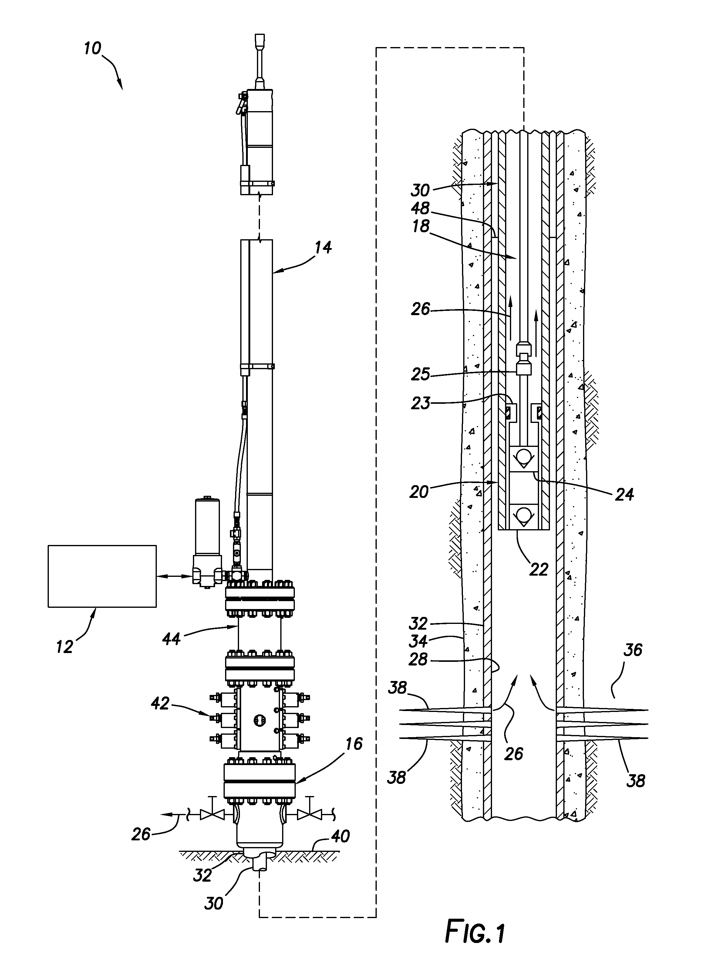
[0006] FIG. 1 is a representative partially cross-sectional view of an example of a well system and associated method which can embody principles of this disclosure.
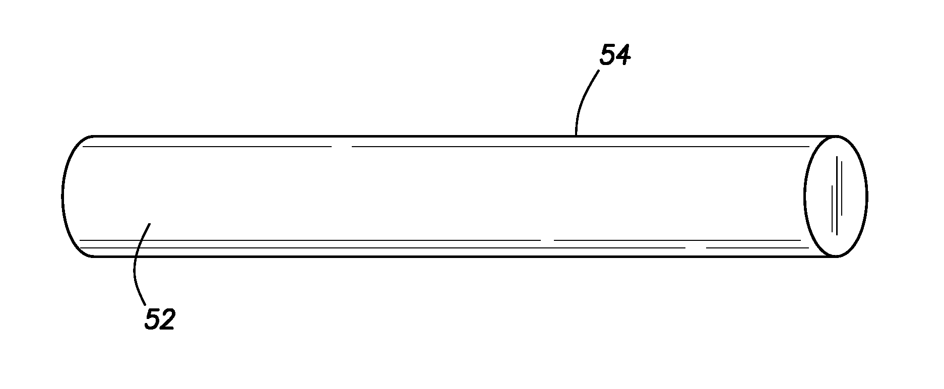
[0007] FIG. 2 is a representative perspective view of an example of a sucker rod material that may be used in a method embodying the principles of this disclosure.
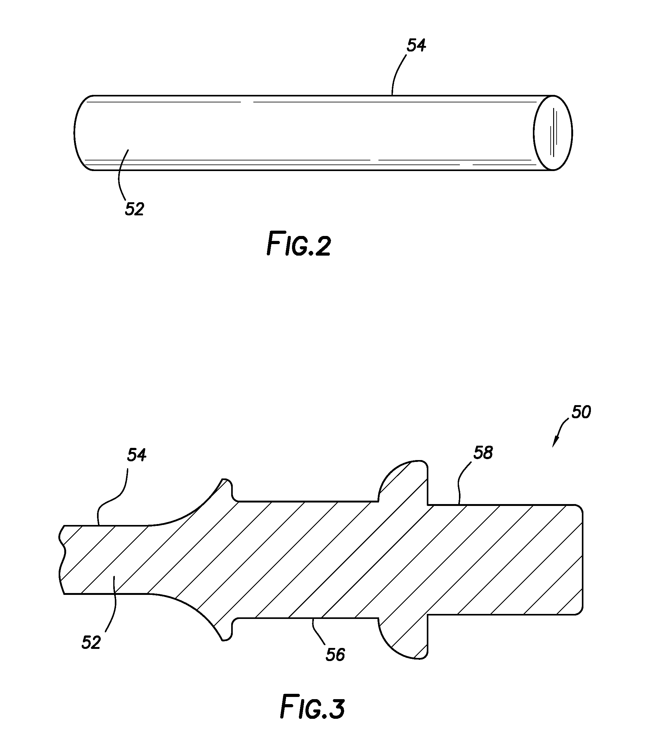
[0008] FIG. 3 is a representative cross-sectional view of a forged sucker rod end.
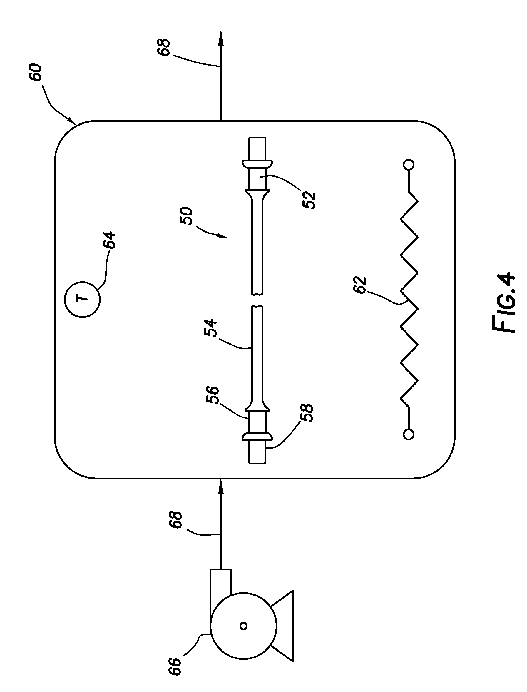
[0009] FIG. 4 is a representative schematic view of a heat treatment procedure that may be used in the method.
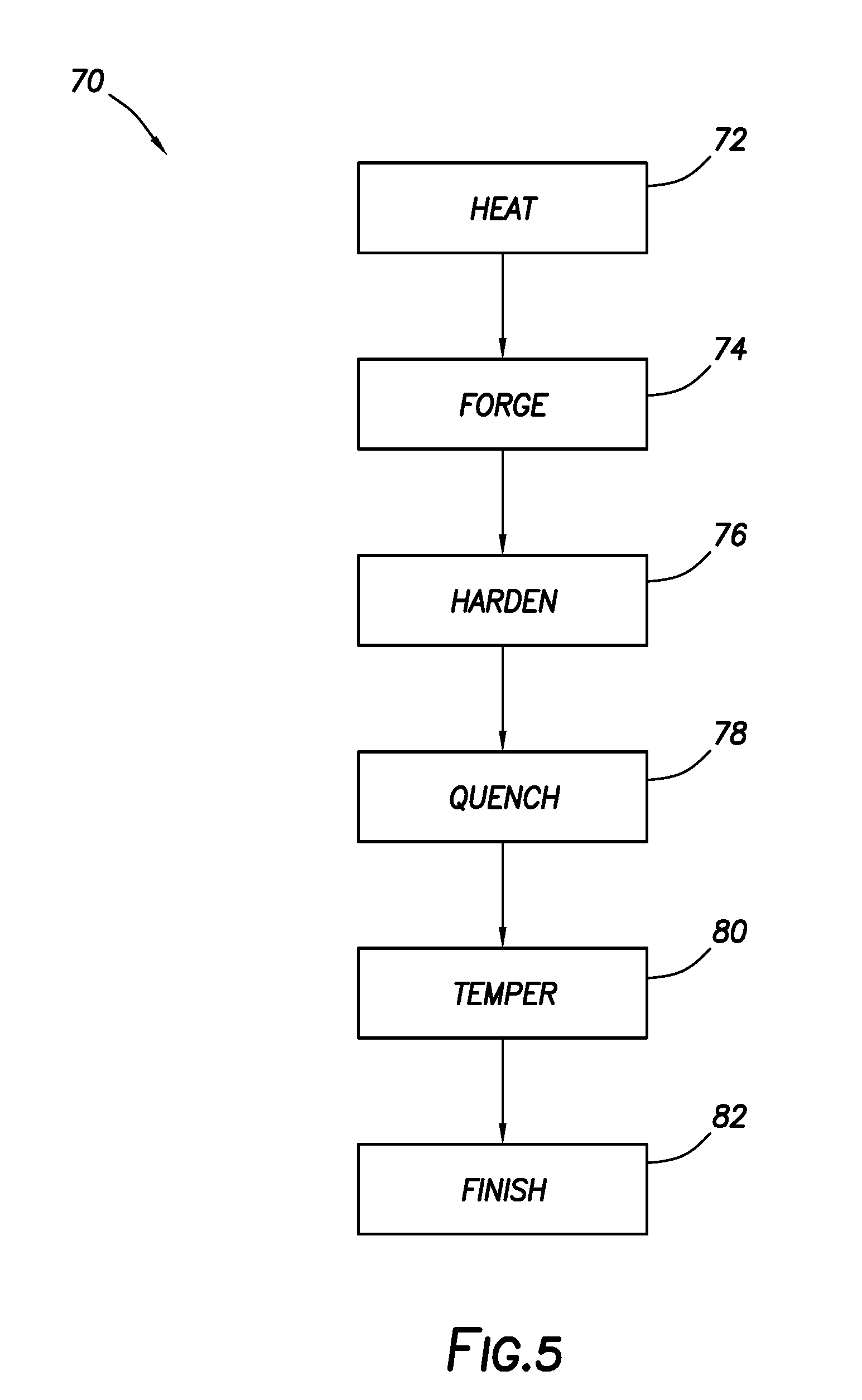
[0010] FIG. 5 is a representative flow chart for an example of a method for producing the sucker rod.
DETAILED DESCRIPTION
[0011] Representatively illustrated in FIG. 1 is an artificial lift system 10 and associated method for use with a subterranean well, which system and method can embody principles of this disclosure. However, it should be clearly understood that the artificial lift system 10 and method are merely one example of an application of the principles of this disclosure in practice, and a wide variety of other examples are possible. Therefore, the scope of this disclosure is not limited at all to the details of the system 10 and method as described herein or depicted in the drawings.
[0012] In the FIG. 1 example, a hydraulic pressure source 12 is used to apply hydraulic pressure to, and exchange hydraulic fluid with, a hydraulic actuator 14 mounted on a wellhead 16. In response, the hydraulic actuator 14 reciprocates a rod string 18 extending into the well, thereby operating a downhole pump 20.
[0013] The rod string 18 is made up of individual sucker rods connected to each other. The rod string 18 communicates reciprocating motion of the hydraulic actuator 14 to the downhole pump 20.
[0014] The downhole pump 20 is depicted in FIG. 1 as being of the type having a stationary or "standing" valve 22 and a reciprocating or "traveling" valve 24. The traveling valve 24 is connected to, and reciprocates with, the rod string 18, so that fluid 26 is pumped from a wellbore 28 into a production tubing string 30. However, it should be clearly understood that the downhole pump 20 is merely one example of a wide variety of different types of pumps that may be used with the artificial lift system 10 and method of FIG. 1, and so the scope of this disclosure is not limited to any of the details of the downhole pump described herein or depicted in the drawings.
[0015] The wellbore 28 is depicted in FIG. 1 as being generally vertical, and as being lined with casing 32 and cement 34. In other examples, a section of the wellbore 28 in which the pump 20 is disposed may be generally horizontal or otherwise inclined at any angle relative to vertical, and the wellbore section may not be cased or may not be cemented. Thus, the scope of this disclosure is not limited to use of the artificial lift system 10 and method with any particular wellbore configuration.
[0016] In the FIG. 1 example, the fluid 26 originates from an earth formation 36 penetrated by the wellbore 28. The fluid 26 flows into the wellbore 28 via perforations 38 extending through the casing 32 and cement 34. The fluid 26 can be a liquid, such as oil, gas condensate, water, etc. However, the scope of this disclosure is not limited to use of the artificial lift system 10 and method with any particular type of fluid, or to any particular origin of the fluid.
[0017] As depicted in FIG. 1, the casing 32 and the production tubing string 30 extend upward to the wellhead 16 at or near the earth's surface 40 (such as, at a land-based wellsite, a subsea production facility, a floating rig, etc.). The production tubing string 30 can be hung off in the wellhead 16, for example, using a tubing hanger (not shown). Although only a single string of the casing 32 is illustrated in FIG. 1 for clarity, in practice multiple casing strings and optionally one or more liner (a liner string being a pipe that extends from a selected depth in the wellbore 28 to a shallower depth, typically sealingly "hung off" inside another pipe or casing) strings may be installed in the well.
[0018] In the FIG. 1 example, a rod blowout preventer stack 42 and an annular seal housing 44 are connected between the hydraulic actuator 14 and the wellhead 16. The rod blowout preventer stack 42 includes various types of blowout preventers (BOP's) configured for use with the rod string 18. For example, one blowout preventer can prevent flow through the blowout preventer stack 42 when the rod string 18 is not present therein, and another blowout preventer can prevent flow through the blowout preventer stack 42 when the rod string 18 is present therein. However, the scope of this disclosure is not limited to use of any particular type or configuration of blowout preventer stack with the artificial lift system 10 and method of FIG. 1.
[0019] The annular seal housing 44 includes an annular seal (described more fully below) about a piston rod of the hydraulic actuator 14. The piston rod (also described more fully below) connects to the rod string 18 below the annular seal, although in other examples a connection between the piston rod and the rod string 18 may be otherwise positioned. The hydraulic pressure source 12 may be connected directly to the hydraulic actuator 14, or it may be positioned remotely from the hydraulic actuator 14 and connected with, for example, suitable hydraulic hoses or pipes.
[0020] The hydraulic pressure source 12 controls pressure in the hydraulic actuator 14, so that the rod string 18 is displaced alternately to its upper and lower stroke extents. These extents do not necessarily correspond to maximum possible upper and lower displacement limits of the rod string 18 or the pump 20.
[0021] For example, it is typically undesirable for a valve rod bushing 25 above the traveling valve 24 to impact a valve rod guide 23 above the standing valve 22 when the rod string 18 displaces downwardly (a condition known to those skilled in the art as "pump-pound"). Thus, it is preferred that the rod string 18 be displaced downwardly only until the valve rod bushing 25 is near its maximum possible lower displacement limit, so that it does not impact the valve rod guide 23.
[0022] On the other hand, the longer the stroke distance (without impact), the greater the productivity and efficiency of the pumping operation (within practical limits), and the greater the compression of fluid between the standing and traveling valves 22, 24 (e.g., to avoid gas-lock). In addition, a desired stroke of the rod string 18 may change over time (for example, due to gradual lengthening of the rod string 18 as a result of lowering of a liquid level (such as at fluid interface 48) in the well, etc.).
[0023] In some situations, the fluid 26 can include substances that cause undesirable corrosion of conventional carbon or low alloy steel sucker rods. For example, the fluid 26 could comprise hydrogen sulfide (H.sub.2S) or carbon dioxide (CO.sub.2).
[0024] In one important aspect, this disclosure provides for production of sucker rods that are corrosion resistant and suitable for use in harsh well environments, such as, where hydrogen sulfide or carbon dioxide is present in the produced fluid 26. However, the scope of this disclosure is not limited to use of the improved sucker rods for any particular purpose, or in any particular environment.
[0025] Referring additionally now to FIG. 2, a sucker rod composition or material 52 is depicted in the form of a cylindrical bar 54 having a suitable length. The bar 54 can be considered as a raw material for producing a sucker rod 50 (see FIGS. 3 & 4). The sucker rod 50 may be used in the rod string 18 described above, or it may be used in other rod strings and in other artificial lift systems, in keeping with the scope of this disclosure.
[0026] In the FIG. 2 example, the sucker rod material 52 comprises a martensitic stainless steel. The material 52 may have a chromium (Cr) content of about 12%, and up to 1.2% carbon (C) content. Where Society of Automotive Engineers (SAE) grade 410, or Unified Numbering System (UNS) grade S41000, stainless steel is used, the material 52 can have a chromium (Cr) content of 11.5-13.0%, nickel (Ni) content of 0.75%, carbon (C) content of up to 0.15%, manganese (Mn) content of 1%, silicon (Si) content of 1%, phosphorus (P) content of 0.04%, and sulfur (S) content of 0.03%.
[0027] In some examples, the sucker rod composition can be tailored to maximize sucker rod performance by incorporating the base composition of UNS S41000, and modifying it by restricting the carbon range. Such modifications can achieve desired mechanical properties, and can include alloy additions that improve properties, such as, toughness and fatigue resistance.
[0028] In such examples of the sucker rod composition or material 52 comprising a modified UNS S41000 base composition, the carbon content can be restricted to 0.08% to 0.15%. Alloying additions can include vanadium additions up to 20%, niobium additions up to 0.10%, titanium additions up to 0.05%, nickel additions up to 0.99%, and/or molybdenum additions up to 1.0%.
[0029] For example, a modified UNS S41000 stainless steel alloy for use as the sucker rod material 52 may comprise a carbon content of 0.08-0.15%, an addition of about 0.05% vanadium, an addition of about 0.5% nickel, and an addition of about 0.20% molybdenum.
[0030] As another example, a modified UNS S41000 stainless steel alloy for use as the sucker rod material 52 may comprise a carbon content of 0.08-0.15%, an addition of about 0.05% vanadium, an addition of about 0.95% nickel, and an addition of about 0.50% molybdenum.
[0031] In yet another example, a modified UNS S41000 stainless steel alloy for use as the sucker rod material 52 may comprise a carbon content of 0.08-0.15%, an addition of about 0.04% niobium, an addition of about 0.5% nickel, and an addition of about 0.20% molybdenum.
[0032] Another modified UNS S41000 stainless steel alloy suitable for use as the sucker rod material 52 may comprise a carbon content of 0.08-0.15%, an addition of about 0.015% titanium, an addition of about 0.5% nickel, and an addition of about 0.20% molybdenum.
[0033] In some examples, a diameter of the bar 54 may be approximately 0.75 inch (.about.1.9 cm). However, the scope of this disclosure is not limited to any particular diameter, length, size or material of the bar 54.
[0034] Referring additionally now to FIG. 3, the sucker rod 50 is depicted after a forging operation. In this example, an end of the bar 54 is heated to a desired forging temperature, and is then deformed using a hammer and die (not shown). When the forging operation is complete, the end of the bar 54 has rough-finished areas for wrench flats 56 and threads 58. The wrench flats 56 and threads 58 may be finished in subsequent steps of the method.
[0035] The forging temperature is selected to provide for ready shaping (deforming) of the bar 54 end, while avoiding formation of .delta.-ferrite crystalline microstructure in the material 52. In one example, the bar 54 end can be satisfactorily forged at approximately 2350.degree. F. (.about.1288.degree. C.)+/-50.degree. F. (.about.28.degree. C.). Other forging temperatures may be used in other examples (e.g., a higher or lower forging temperature may be used depending on a cross-section of the material 52).
[0036] Referring additionally now to FIG. 4, the sucker rod 50 is depicted in a heat-treating operation. Where the ends of the bar 54 are forged (for example, as described above in relation to FIG. 3), the heat-treating operation may be performed after the forging operation.
[0037] As depicted in FIG. 4, the sucker rod 50 is placed in a heat treatment furnace or oven 60. In the FIG. 4 example, the oven 60 includes a burner or heating element 62, a temperature sensor 64 and a blower 66. The blower 66 can force air 68 to flow at a desired flow rate through the oven 60 to thereby reduce a temperature of the sucker rod 50 after a hardening step described more fully below.
[0038] The heating element 62 is depicted in FIG. 4 as an electrical resistance element, but other types of heating sources (such as, a fuel-fired burner) may be used in other examples. The temperature sensor 64 may comprise any of various types of temperature sensors and indicators (such as, a pyrometer, a thermocouple, etc.).
[0039] The heating element 62, temperature sensor 64 and blower 66, or any of them, may be connected to a control system (not shown) for automatically controlling the temperature in the oven 60, for maintaining a desired temperature, and for controlling the time spent at a particular temperature. The control system could include, for example, a programmable logic controller (PLC) utilizing a proportional-integral-derivative (PID) algorithm. Alternatively, temperatures and times in the heat treatment operation may be manually controlled. Thus, the scope of this disclosure is not limited to any particular means for controlling temperature in the heat treatment operation.
[0040] In this example, the heat treatment operation comprises increasing the temperature of the sucker rod 50 to greater than the martensite transformation temperature for the material 52, and then air quenching. The sucker rod 50 is then tempered to its final state by reheating, thereby achieving satisfactory levels of corrosion resistance, hardness, strength, toughness and impact resistance.
[0041] For example, the temperature of the sucker rod 50 can be maintained at approximately 1800.degree. F. (.about.982.degree. C.)+/-15.degree. F. (.about.8.degree. C.) for approximately 30 minutes to thereby harden the material 52. The sucker rod 50 can then be air quenched by flowing air 68 at approximately 15 cubic feet per minute (.about.425 liters per minute) +/-5 cubic feet per minute (.about.142 liters per minute) across the sucker rod.
[0042] After the air quenching, the sucker rod 50 can be tempered. For example, the sucker rod 50 may be tempered by increasing its temperature to approximately 1200.degree. F. (.about.649.degree. C.)+/-25.degree. F. (.about.14.degree. C.) and maintaining that temperature for approximately 45 minutes to one hour.
[0043] In one example, a 1.9 cm diameter SAE grade 410 stainless steel bar 54 can be forged at approximately 1288.degree. C., hardened by heating to 982.degree. C. for approximately 30 minutes, air quenched by forced air at approximately 15 cubic feet per minute (.about.25 liters per minute), and then tempered at approximately 649.degree. C. for approximately 45 minutes. Such heat treated material 52 can have an Izod impact energy value of approximately 87 foot-pounds (.about.118 Nm), elongation of approximately 21%, reduction of area of approximately 69%, tensile strength of approximately 127,600 pounds per square inch (.about.880 MPa), and yield strength of approximately 107,200 pounds per square inch (.about.740 MPa).
[0044] Referring additionally now to FIG. 5, an example flow chart for a method 70 of producing a sucker rod is representatively illustrated. For clarity and conciseness of description, the method 70 is depicted in FIG. 5 and described below as it may be utilized for producing the sucker rod 50 of FIGS. 3 & 4 for use in the artificial lift system 10 of FIG. 1.
[0045] However, it should be clearly understood that, in other examples, the method 70 could be utilized for producing other types of sucker rods for use in other types of artificial lift systems. Accordingly, the scope of this disclosure is not limited to any particular details of the method 70 as described herein or depicted in the drawings.
[0046] In step 72, the material 52 is heated to a forging temperature in preparation for forging (step 74). For an SAE grade 410 or UNS grade S41000 martensitic stainless steel material, the forging temperature may be approximately 2350.degree. F. (1288.degree. C.)+/-50.degree. F. (.about.28.degree. C.). The forging temperature may vary based on, for example, material selection, cross-sectional thickness, extent of deformation, etc. The forging temperature can be selected to allow the material 52 to be deformed as desired with relatively few hammer strikes, and to mitigate formation of undesirable phases such as .delta.-ferrite in the material.
[0047] In step 74, the material 52 is forged to a desired shape, soon after the forging temperature is reached. In this example (see FIG. 3), the end of the bar 54 is struck with a hammer and die, so that the end of the bar is configured for wrench flats 56 and threads 58. In other examples, different configurations or shapes may be used.
[0048] In some examples, the material 52 may not be forged at all. In such examples, the steps 72 and 74 may not be performed.
[0049] In steps 76, 78 and 80, a heat treatment procedure is performed. These steps increase a hardness and strength of the material 52, while also providing for suitable toughness and impact resistance.
[0050] In step 76, the material 52 is hardened by holding the material at a certain elevated temperature for a certain duration. For an SAE grade 410 or UNS grade S41000 martensitic stainless steel material, the elevated temperature may be approximately 1800.degree. F. (.about.982.degree. C.)+/-15.degree. F. (.about.8.degree. C.), and the duration may be approximately 30 minutes. Other hardening temperatures and times may be used in other examples.
[0051] In step 78, the material 52 is quenched. In this example, an air quenching technique is used. In the FIG. 4 example, the blower 66 flows air 68 across the sucker rod 50 at a flow rate of approximately 15 cubic feet per minute (.about.25 liters per minute)+/-5 cubic feet per minute (.about.142 liters per minute). Other flow rates may be used in other examples, with the flow rate varying based on factors, such as, mass of the material 52, desired quench rate, etc.
[0052] In step 80, the material 52 is tempered by increasing its temperature to a certain tempering temperature, and maintaining that temperature for a certain duration. For an SAE grade 410 or UNS grade S41000 martensitic stainless steel material, the tempering temperature may be approximately 1200.degree. F. (.about.649.degree. C.)+/-25.degree. F. (.about.14.degree. C.), and the duration may be approximately 45 minutes to one hour. Other tempering temperatures and durations may be used in other examples.
[0053] In step 82, the sucker rod 50 is finished. For example, the wrench flats 56 may be finish machined to a desired size, and the threads 58 may be formed on the end of the bar 54. Internal or external threads, or other types of connection means, may be formed. The provisions for wrench flats 56 and threads 58 depicted in FIG. 3 are optional, since the forging steps 72, 74 are also optional, and other types of sucker rod ends may be used in other examples.
[0054] In some examples, a portion or all of the finishing may be performed prior to the heat treatment steps 76, 78, 80. None or less than all of the finishing may be performed after the heat treatment steps 76, 78, 80.
[0055] It may now be fully appreciated that the above disclosure provides significant advancements to the art of artificial lift systems, including the art of producing sucker rods for use in artificial lift systems. In one example described above, a sucker rod 50 can be formed of a martensitic stainless steel (such as, SAE grade 410 or UNS grade S41000), which is hardened and air quenched. The sucker rod 50 has desirable corrosion resistance, along with strength, toughness and impact resistance, suitable for use in a harsh well environment.
[0056] A method 70 of producing a sucker rod 50 for use in a subterranean well is provided to the art by the above disclosure. In one example, the method can include the steps of: maintaining a temperature of a martensitic stainless steel material 52 of the sucker rod 50 at approximately an elevated temperature; and then air quenching the material 52.
[0057] The elevated temperature may be approximately 982.degree. C.+/-8.degree. C. The elevated temperature may be maintained for approximately 30 minutes.
[0058] The method may include tempering the material 52 after the air quenching step. The tempering may comprise maintaining the temperature of the material 52 at a tempering temperature of approximately 649.degree. C.+/-14.degree. C. The tempering may comprise maintaining the material 52 at the tempering temperature for a duration of approximately 45 minutes to approximately one hour.
[0059] The method may include forging the material 52. The forging step may comprise elevating the temperature of the material 52 to approximately 1288.degree. C.+/-28.degree. C. prior to deforming the material 52.
[0060] The forging step may include configuring the sucker rod 50 for forming on the material 52 at least one of wrench flats 56 and threads 58.
[0061] The method may include restricting a carbon content of the material to the range of 0.08% to 0.15%. In some examples, the material 52 comprises up to 0.20% vanadium content, up to 0.10% niobium content, up to 0.05% titanium content, up to 0.99% nickel content and/or up to 1.0% molybdenum content.
[0062] The above disclosure also provides to the art a sucker rod 50 produced by the method 70 described above.
[0063] Another sucker rod 50 is also provided for use in a subterranean well. In this example, the sucker rod 50 can comprise a stainless steel sucker rod composition 52 in which a carbon content is restricted to the range of 0.08% to 0.15%, and in which the sucker rod composition 52 includes at least one of the group consisting of: up to 0.20% vanadium content, up to 0.10% niobium content, up to 0.05% titanium content, up to 0.99% nickel content and up to 1.0% molybdenum content.
[0064] The sucker rod composition 52 may include about 0.05% vanadium content, about 0.5% nickel content, and about 0.20% molybdenum content.
[0065] The sucker rod composition 52 may include about 0.05% vanadium content, about 0.95% nickel content, and about 0.50% molybdenum content.
[0066] The sucker rod composition 52 may include about 0.04% niobium content, about 0.5% nickel content, and about 0.20% molybdenum content.
[0067] The sucker rod composition 52 may include about 0.015% titanium content, about 0.5% nickel content, and about 0.20% molybdenum content.
[0068] A chromium content of the sucker rod composition 52 may be from 11.5 to 13.0%.
[0069] Another method described above (e.g., the method 70 of FIG. 5 combined with the method of FIG. 1) can include: producing multiple sucker rods 50, the producing comprising maintaining a temperature of a martensitic stainless steel material 52 of the sucker rods 50 at approximately an elevated temperature, and then air quenching the material 52; connecting the sucker rods 50 in a rod string 18, the connecting including connecting the rod string 18 to a downhole pump 20; and operating the downhole pump 20, thereby flowing a fluid 26 from the well.
[0070] The above disclosure also provides an artificial lift system 10 produced by the method described above.
[0071] Although various examples have been described above, with each example having certain features, it should be understood that it is not necessary for a particular feature of one example to be used exclusively with that example. Instead, any of the features described above and/or depicted in the drawings can be combined with any of the examples, in addition to or in substitution for any of the other features of those examples. One example's features are not mutually exclusive to another example's features. Instead, the scope of this disclosure encompasses any combination of any of the features.
[0072] Although each example described above includes a certain combination of features, it should be understood that it is not necessary for all features of an example to be used. Instead, any of the features described above can be used, without any other particular feature or features also being used.
[0073] It should be understood that the various embodiments described herein may be utilized in various orientations, such as inclined, inverted, horizontal, vertical, etc., and in various configurations, without departing from the principles of this disclosure. The embodiments are described merely as examples of useful applications of the principles of the disclosure, which is not limited to any specific details of these embodiments.
[0074] In the above description of the representative examples, directional terms (such as "above," "below," "upper," "lower," etc.) are used for convenience in referring to the accompanying drawings. However, it should be clearly understood that the scope of this disclosure is not limited to any particular directions described herein.
[0075] The terms "including," "includes," "comprising," "comprises," and similar terms are used in a non-limiting sense in this specification. For example, if a system, method, apparatus, device, etc., is described as "including" a certain feature or element, the system, method, apparatus, device, etc., can include that feature or element, and can also include other features or elements. Similarly, the term "comprises" is considered to mean "comprises, but is not limited to."
[0076] Of course, a person skilled in the art would, upon a careful consideration of the above description of representative embodiments of the disclosure, readily appreciate that many modifications, additions, substitutions, deletions, and other changes may be made to the specific embodiments, and such changes are contemplated by the principles of this disclosure. For example, structures disclosed as being separately formed can, in other examples, be integrally formed and vice versa. Accordingly, the foregoing detailed description is to be clearly understood as being given by way of illustration and example only, the spirit and scope of the invention being limited solely by the appended claims and their equivalents.
* * * * *
D00000
D00001
D00002
D00003
D00004
XML
uspto.report is an independent third-party trademark research tool that is not affiliated, endorsed, or sponsored by the United States Patent and Trademark Office (USPTO) or any other governmental organization. The information provided by uspto.report is based on publicly available data at the time of writing and is intended for informational purposes only.
While we strive to provide accurate and up-to-date information, we do not guarantee the accuracy, completeness, reliability, or suitability of the information displayed on this site. The use of this site is at your own risk. Any reliance you place on such information is therefore strictly at your own risk.
All official trademark data, including owner information, should be verified by visiting the official USPTO website at www.uspto.gov. This site is not intended to replace professional legal advice and should not be used as a substitute for consulting with a legal professional who is knowledgeable about trademark law.