Transport Device And Method For Controlling And Monitoring The Elongation Of A Transport Device
Wagner; Stefan ; et al.
U.S. patent application number 16/099253 was filed with the patent office on 2019-07-11 for transport device and method for controlling and monitoring the elongation of a transport device. The applicant listed for this patent is KHS GmbH. Invention is credited to Josef Dupper, Thomas Lelie, Andreas Linder, Dominik Thiesing, Stefan Wagner, Reinhard Wilzeck.
| Application Number | 20190210813 16/099253 |
| Document ID | / |
| Family ID | 58992839 |
| Filed Date | 2019-07-11 |

| United States Patent Application | 20190210813 |
| Kind Code | A1 |
| Wagner; Stefan ; et al. | July 11, 2019 |
TRANSPORT DEVICE AND METHOD FOR CONTROLLING AND MONITORING THE ELONGATION OF A TRANSPORT DEVICE
Abstract
An apparatus for transporting containers or packs of containers includes an endlessly circulating belt driven by a drive. A mark marks a position on the belt and a sensor detects the mark. A controller receives data from the drive's rotation-angle detector and from the sensor. It then uses this data to either determine an extent to which the belt has elongated or to control the drive.
| Inventors: | Wagner; Stefan; (Kleve, DE) ; Linder; Andreas; (Witten, DE) ; Thiesing; Dominik; (Hamminkeln, DE) ; Lelie; Thomas; (Kleve, DE) ; Dupper; Josef; (Bedburg-Hau, DE) ; Wilzeck; Reinhard; (Kleve, DE) | ||||||||||
| Applicant: |
|
||||||||||
|---|---|---|---|---|---|---|---|---|---|---|---|
| Family ID: | 58992839 | ||||||||||
| Appl. No.: | 16/099253 | ||||||||||
| Filed: | May 24, 2017 | ||||||||||
| PCT Filed: | May 24, 2017 | ||||||||||
| PCT NO: | PCT/EP2017/062674 | ||||||||||
| 371 Date: | November 6, 2018 |
| Current U.S. Class: | 1/1 |
| Current CPC Class: | B65G 43/02 20130101; B65G 43/04 20130101; B65G 43/10 20130101; B65G 23/44 20130101; B65G 43/00 20130101 |
| International Class: | B65G 43/10 20060101 B65G043/10 |
Foreign Application Data
| Date | Code | Application Number |
|---|---|---|
| Jun 22, 2016 | DE | 10 2016 111 421.9 |
Claims
1-15. (canceled)
16. An apparatus for transporting objects selected from the group consisting of containers and packs of containers, said apparatus comprising a belt, a drive, a controller, a sensor, a mark, and an angle detector, wherein said belt is an endlessly-circulating belt, said drive drives said belt, and said controller controls said drive, wherein said mark marks a position on said belt, wherein said sensor detects said mark, wherein said drive comprises said angle detector, wherein said controller receives data from said rotation-angle detector and said sensor, and wherein said controller is configured to carry out a task selected from the group consisting of a first task and a second task, wherein said first task is that of calculating, based at least in part on said data, an extent to which said belt has elongated, and wherein said second task is that of controlling said drive based at least in part on said data.
17. The apparatus of claim 16, wherein there exists no more than one sensor per belt.
18. The apparatus of claim 16, wherein there exists no more than one mark per belt.
19. The apparatus of claim 16, wherein said sensor is a first sensor, wherein said apparatus comprises a second sensor that is identical to said first sensor, wherein said first and second sensors are offset relative to each other along said belt, wherein said first and second sensors interact with said controller such that said controller processes data from each sensor with data from said rotary-angle detector to permit execution of said task for a designated section of said belt.
20. The apparatus of claim 16, wherein said sensor and said drive are separated by a distance, wherein said distance is at least 95% of the length of a drive side of said belt.
21. The apparatus of claim 16, wherein a switching tag secured to said belt forms said mark.
22. The apparatus of claim 16, wherein said belt is a first belt and said controller is a first controller, wherein said apparatus further comprises a second belt and a second controller that controls said second belt, wherein said first and second controllers cooperate to synchronize speeds of said first and second belts.
23. The apparatus of claim 22, wherein said first and second belts are arranged such that said objects are transferred from said first belt to said second belt.
24. The apparatus of claim 22, wherein said first and second belts are arranged such that there exists a section of said first belt and a section of said second belt that are parallel to each other.
25. The apparatus of claim 16, wherein said task is said first task.
26. The apparatus of claim 16, wherein said task is said second task.
27. A method comprising controlling and monitoring a conveyor that comprises an endlessly circulating belt that is driven by a drive and that includes a rotation-angle detector and a stationary sensor for detecting a mark on said belt, wherein controlling and monitoring said conveyor comprises detecting said mark, storing a first reference rotation angle that is associated with detection of said mark, determining a second rotation angle that is associated with said mark's position, determining that said first and second rotation angles differ from each other, and, based at least in part on said difference, executing a task selected from a first task and a second task, wherein said first task comprises determining an extent to which said belt has elongated and wherein said second task comprises regulating said drive's speed.
28. The method of claim 27, further comprising regulating said belt's speed and regulating a further belt's speed.
29. The method of claim 27, further comprising detection an additional mark, obtaining a rotation angle associated with said additional mark, and wherein executing said task comprises executing said task based at last in part on said rotation angle associated with said additional mark.
30. The method of claim 27, wherein executing said task comprises executing said task based at last in part on a comparison between rotation angles derived from measurements by plural sensors opposite said belt and corresponding reference rotation angles.
31. The method of claim 27, further comprising, concurrently with determining said rotation angle, using an additional sensor to detect a cross-influence and wherein determining that said first and second rotation angles differ from each other comprises correcting a comparison between said first and second rotation angles based at least in part on said cross-influence.
32. The method of claim 27, wherein said belt is a first belt and wherein said method further comprises receiving data indicative of a rotation angle of an additional belt and using said data to regulate said first belt so as to adjust said second belt.
33. The apparatus of claim 16, further comprising a cross influence sensor that provides information indicative of a cross influence to said controller.
Description
[0001] The invention relates to a device for transporting containers or multi-packs, comprising an endlessly circulating transport element, a drive unit for driving the circulating transport element, a control unit for controlling the drive unit, and at least one stationary sensor for sensing at least one position of the transport element. The invention further relates to a method for controlling and monitoring a transport device.
[0002] Devices for transporting containers or multi-packs and methods for controlling and monitoring such transport devices are known in many configurations from the prior art. Corresponding devices and methods are used in this situation in the manufacture and packing of goods, in particular foodstuffs. Corresponding transport devices, however, are also used in many other sectors, in particular in the production, processing, or storage of merchandise and goods.
[0003] A known problem with such transport devices is that the endlessly circulating transport elements, in most cases belts or chains, undergo a change of length over the course of time in use. These changes in length occur on the one hand uniformly over the entire transport element, due to forces which take effect during the period of use and depending on the material of the transport device. On the other hand, however, changes in length may also occur on the transport element, depending on the location, due to different properties, such as different material thickness, hardening of a metal, or cross-linking of a polymer. Other external influences can also contribute to changes in length, such as dirt contamination, temperature changes, the humidity, or the respective lubrication.
[0004] These changes in length lead on the one hand, with increasing duration of use, to the probability increasing of a malfunction of the transport device, in particular due to an elongation of the transport element, which results in the transport device having to be taken out of service regularly in order to measure the elongation which has already occurred, and, if necessary, to the transport device being replaced in order to prevent a breakdown and possible consequential damage.
[0005] On the other hand, a change of length of the transport element leads to the situation, with the constant operation of the drive unit, that the speed of the transport element changes as a function of the change of length. Due to this, asynchronicity may occur between the transport device and other devices interacting with it, or other parallel or downstream transport devices. In a transfer region from one transport device to a further transport device, in particular, it is of decisive importance that the adjoining transport devices exhibit synchronous speeds, in order to avoid undesirable forces being exerted on the transported containers or multi-packs due to relative speeds occurring in the transfer region. Likewise, in situations with a plurality of transport devices arranged parallel to one another, a difference in speed leads to an undesirable rotation of the transported containers or multi-packs in relation to the transport device.
[0006] With conventional devices from the prior art, in order to solve these problems, at least two sensors are arranged along the endlessly circulating transport element, which monitor at least one identifying feature on the transport element.
[0007] By way of example, from DE 60 2004 006 459 T2 a method and device are known for monitoring the wear of chain links, wherein a circulating chain exhibits two identification features which can be detected by two sensors. In this situation, the first sensor is arranged secured to the device, while the second sensor can be displaced along the chain. With the method, the second sensor is positioned along the chain in such a way that both sensors in each case detect an identifying feature simultaneously. In the event of an elongation of the chain, a time delay occurs in the actuation of the two sensors, wherein the elongation of the chain is determined in that the second sensor moves until the synchronicity of the signals is established, and the distance covered by the second sensor which is needed for this is determined.
[0008] From U.S. Pat. No. 5,563,392 A, a method and a corresponding device are known for monitoring the wear of a continuous chain. In the device, two sensors are arranged at a constant distance interval from one another along the direction of run of the chain, in order to detect the gaps between the individual chain links. In this situation, both sensors are arranged in such a way that, with a chain which has not undergone elongation, in each case they simultaneously measure a passage of a chain link. In the event of an elongation of the chain, asynchronicity of the detection occurs, wherein, from the time difference of the detection of a chain link, the elongation can be calculated.
[0009] In addition to this, methods and devices are also known from the prior art which make use of only one sensor and a plurality of identification features on the circulating transport element in order to identify an elongation of the transport element. For example, with the device disclosed in DE 11 2004 001 238 T5 for measuring the elongation of a conveyor belt, a plurality of magnets are embedded in the conveyor belt at a consistent distance interval from one another, wherein a magnetism sensor is arranged at the conveyor belt, which from the time change of the detected magnetic field, determines the elongation of the conveyor belt.
[0010] Such configurations from the prior art have the disadvantage, however, that either a plurality of sensors must be arranged along the transport element, which leads to a complex structure as well as high manufacturing costs, or the transport element must comprise a plurality of identifying features, which results in a high price of the transport element, which as a part subject to wear must be replaced on a regular basis. With the use of a plurality of sensors, the measurement result is also regularly negatively influenced, in that the position of the sensors changes in relation to one another or to the transport means respectively, in particular due to a thermal elongation of the transport device as temperatures rise during operation, or due to mechanical influences, and the precision of the measurements therefore decreases.
[0011] The task is now to provide a device for the manufacture of containers or multi-packs, as well as a corresponding method, which in a particularly simple manner and with particularly few components allows for reliable monitoring of the elongation of a transport element, as well as precise controlling of the speed of the transport element, and in this situation can be manufactured and operated particularly economically.
[0012] The object is solved according to the invention by a device according to claim 1 and a method according to claim 10. Advantageous further embodiments of the invention are provided in the dependent claims.
[0013] The device according to the invention for the transport of containers or multi-packs comprises an endlessly circulating transport element, a drive unit for driving the circulating transport element, a control unit for controlling the drive unit, and at least one stationary sensor for detecting at least one position mark of the transport element. According to the invention, the drive unit comprises a means for outputting the position or setting, in particular a rotation angle detector. In this situation, the control unit is connected to the means for outputting the position or setting, as well as to the sensor, in such a way that, by means of the data from the means for outputting the position or setting and from the sensor, the drive unit can be actuated and/or an elongation of the transport element can be calculated.
[0014] The inventors of the device have recognised that it is not necessary to have two sensors arranged at a transport element with a position mark in order to achieve a reliable identification of the actual speed and/or of the rotation of the transport element, but that, also by means of a sensor and of a rotation angle detector arranged in the drive unit, the monitoring and/or controlling of the device is possible in an even simpler manner. In addition to this, the absence of a second sensor along the transport element leads to an advantageous simplification of the structural arrangement and to savings on manufacturing costs. In addition to this, the detection is also more precise and reliable, since the rotation angle detector is usually integrated in the interior of the drive unit, and therefore exhibits less susceptibility to interfering influences.
[0015] With the method according to the invention for controlling and monitoring a transport device, with an endlessly circulating transport element driven by a drive unit with a rotation angle detector, and a stationary sensor for detecting a position mark of the transport element, first a first rotation angle is detected by means of the rotary angle detector, during the detection of the position mark by the sensor, and is stored in a control unit as a reference rotation angle. Next, the determination of at least one further rotation angle takes place, with a repeat detection of the position mark by the sensor and transfer of this to the control unit. The rotation angle which is detected is then compared with the reference rotation angle in the control unit, and, by means of the result obtained from the comparison or from the time change in the results obtained, a regulation takes place of the speed of the drive unit and/or a determination of the elongation of the transport element.
[0016] The method according to the invention allows in a particularly simple manner, in the event of the occurrence of tribological effects in the region of the transport element, in particular a change of length and therefore an elongation, for this to be determined, since, if the transport element is elongated, the position mark reaches the sensor later in relation to the measured rotation angle. It is also possible for the speed of the transport element to be adjusted, in particular by a corresponding acceleration of the drive unit, and to keep it constant over the entire duration of operation. This is particularly important in ensuring a problem-free transfer of the transported containers or multi-packs from or to the transport element, for example at a transfer from a transport star or onto a further transport element. A speed which has not been adjusted can lead not only to undesirable forces being exerted on the container or the multi-pack, but also cause a rotation of the container or multi-pack, and thereby rendering the following work steps more difficult.
[0017] The device according to the invention is suitable for the transport of containers and/or multi-packs by means of a transport element. Containers in this context are, in particular, bottles, cans, or kegs made of metal, glass, plastic, and/or a material composite. A multi-pack is understood in the first instance to be any arrangement of at least two containers, preferably at least four, and for particular preference at least six containers, wherein the containers are arranged in a spatially predetermined position in relation to one another. In this situation the containers are in principle arranged immediately next to one another, for example by means of an adhesive bond, but can also be connected to one another by means of a further element.
[0018] The transport element is in the first instance any desired component or any desired module which is suitable for the transport of a plurality of containers or multi-packs, wherein the containers or multi-packs, preferably at least section by section, and preferably completely, stand or lie during the transport on the transport element. For particular preference, the transport element is a transport belt or a transport chain. Preferably, the transport belt is formed in this situation from plastic, rubber, and/or a fabric, and for particular preference comprises a fibre reinforcement or an embedded reinforcement fabric. In particular, the transport belt is configured as being of one piece. A transport chain is preferably formed from a plurality of chain links made of metal and/or plastic, wherein for particular preference all the chain links are configured as identical.
[0019] According to the invention, the transport element is configured as endlessly circulating, i.e. the transport element does not have any end in one spatial direction, in particular the direction of movement in the device for transport, but is configured and arranged in the device in such a way that, after a complete circulation, a point on the transport element is again located at the same position. For this purpose the transport element in the device is deflected at least twice, wherein the deflection takes place in principle by means of any desired deflection element, preferably by means of at least one drive roller of the drive unit and/or at least one deflection roller. For particular preference the transport element is deflected at one end at the drive unit, and at the other end by means of a deflection roller.
[0020] The drive unit according to the invention can in principle be any desired module which is provided for driving the transport element. In this situation, the drive unit can comprise, as well as a motor, also further components such as transmission units, axles, deflection or drive rollers, in particular for the transport element. The drive unit in principle comprises a motor with a rotation angle detector or with means for outputting the position or setting. In particular, the motor is an electric motor or an electromagnetic drive. For particular preference, the motor is a servomotor with an integrated rotation angle detector. For further preference the motor is steplessly adjustable.
[0021] A rotation angle detector is understood in the first instance to be any desired means for outputting the position or setting of the drive unit, in particular an output axle of the drive unit or of a drive axle of the transport element. In principle, the rotation angle detector is a sensor which detects a rotation angle or a measurement value for the rotation angle. Preferably, the rotation angle detector is an incremental detector for detecting an angle change, in particular in the sense of a digital endless potentiometer. The measurement by the rotation angle detector can take place in any desired manner, for example by photoelectric scanning, a sliding contact, magnetic scanning, or by means of a cogwheel sensor. For particular preference, the rotary angle detector is integrated in a motor, in particular in the servomotor of the drive unit.
[0022] Correspondingly, the specific rotation angle can be an actual angle value, but it can also be any desired value representing an angle. Moreover, the rotation angle or rotation angle value can also be determined in the first instance by means of the control unit, for example if the rotation angle detector is an incremental detector, and it is only in the control unit, by means of the known number of increments representing one full rotation, that the respective angle value is determined. The same also applies accordingly to the reference rotation angle.
[0023] The control unit is, in principle, a data processing system which is well suited for recording and storing signals from a plurality of sensors, but at least from the sensor for the position mark of the transport element and of the rotary angle detector. In addition to this, it is possible, by means of the control unit, at least partially and preferably completely, for a processing of the measured sensor data and/or controlling of the drive unit to be carried out. The control unit preferably comprises a user interface or an interface for connecting a device which comprises a user interface. Likewise preferably, the control unit comprises at least one further interface for coupling to at least one further control unit. For particular preference, the control unit is digitally programmable, wherein the programming can take place by means of a user interface of the control unit, but also by means of a further data processing system which can be connected to the control unit, in particular a computer or tablet. For further preference the user interface comprises both input means, for example keyboards, as well as output means, such as a visual display unit, wherein for very particular preference a touchscreen is provided as input and output means simultaneously. For particular preference, the control unit is a memory-programmable control unit (PLC). Likewise preferably, the control of the drive unit and/or the calculation of the elongation of the transport element takes place entirely by means of the control unit.
[0024] The connection of the control unit to the at least one sensor as well as to the rotation angle sensor can in principle take place in any desired manner. In this situation, both a wireless connection is possible, for example by means of radio or radio frequency, infrared, or by some other means by optical signals or radio signals, as well as by means of an electrical conductor or a fibre optic cable. For particular preference, the connection is provided in each case by means of an electrical conductor. Additionally, the sensor and/or the rotation angle detector can be connected both directly to the control unit, as well as by means of further components, such as encoders, transformers, or the like.
[0025] The sensor can be any desired sensor which is suitable for detecting the position mark of the transport element. In this situation, in the simplest case, this can be a mechanical sensor, such as a switch, which is actuated directly by the position marker passing, or by further components. It may also be a contactless sensor, which in particular detects the position mark optically or electromagnetically. The detection can in this situation be quantitative or digital, wherein it is only detected that the position mark is located in the measurement range of the sensor. As an alternative, a quantitative or analog measurement can also be carried out, with which the strength of the signal or another characteristic is determined at the detection of the position mark.
[0026] In this situation the sensor is in principle secured stationary at the device, such that, during operation and/or during the method according to the invention, the sensor does not need to be moved or can be moved. In principle, the sensor can also be secured at the device as movable, for example pivotable, for example so as to facilitate cleaning of the transport element, but the position of use of the sensor must be stationary, i.e. consistent and immovable. Preferably, however, the sensor is arranged at the device such that it can be aligned, such that the sensor can be used in an ideal position for the identification of the position mark and can be secured there such as to be stationary.
[0027] The position marker is a component, or, alternatively, a part of the transport element, which is configured in such a way, and differs from the other transport element in such a way, that it can be reliably detected by means of the sensor. Preferably, the position mark is located on a surface of the transport element which faces away from the counter-running side of the endlessly circulating transport element, and/or is located in a mounting position of the device on the upper side of the transport element, to receive containers or multi-packs. For further preference, the position mark is arranged in such a way at the edge of the transport element in such a way that containers or multi-packs being transported on the transport element cannot cover the position mark.
[0028] The controlling of the drive unit or drive element respectively by means of the control unit involves for preference a dynamic control arrangement, i.e. the data from the sensor and from the rotation angle detector is processed directly, and the control of the speed of the drive element is likewise effected directly, in particular at each detection of the position mark by the sensor. As an alternative, an adjustment of the speed can also only take place after a specified number of actuations of the sensor, for example after every tenth or one hundredth actuation of the sensor.
[0029] The storing of the reference rotation angle can be actuated either manually, for example by means of a button or a user interface, or automatically, for example by means of a sensor for replacing the transport element. Preferably, a determination of the reference angle takes place after a change and/or after a predefined run-in period of a new transport element.
[0030] According to the invention, at a renewed detection of the position mark, carried out following the determination of the reference rotation angle, a rotation angle is determined, in order to be able to compare this with the reference rotation angle. This preferably takes place within the framework of a continuous determination of the rotation angle at each detection of the position mark by the sensor, as a result of which, advantageously, account can be taken not only of the influence of wear of the transport element, but also of the influence of containers or multi-packs which are present on the transport element.
[0031] As an alternative, however, a discontinuous determination of the same rotation angle or further rotation angles can take place at predetermined longer intervals of time, for example hourly, daily, or weekly.
[0032] A preferred embodiment of the device according to the invention comprises precisely one sensor per transport element, as a result of which a particularly favourable production of the device is possible. In particular, the device preferably comprises precisely one sensor at the transport element. Likewise preferred is an embodiment of the device with precisely one position mark per transport element, as a result of which the transport element, which as a part subject to wear must regularly be renewed, can be manufactured particularly simply and economically.
[0033] With a further preferred embodiment of the device according to the invention, at least two identical sensors are arranged offset in relation to one another along the transport element, and in this situation interact with the control unit in such a way that the data from each sensor can be processed with data from the rotation angle detector, in order to allow for a determination initiated section by section of the elongation of the transport element, and/or a dynamic speed control of the drive unit, initiated section by section. As a result, both an irregular elongation of the transport element as well as a different loading, for example due to a fluctuating number of containers or multi-packs present on the transport element, can be monitored and taken into account in the controlling of the speed of the transport element. Accordingly, in a particularly simple manner, even with irregular elongation of the transport element, a uniform speed regulation is possible. For this purpose, the sensors are preferably arranged at the opposing ends or sides of the transport element, offset to one another. For particular preference, the distance interval between adjoining sensors is the same along the transport element. With the use of a plurality of sensors, likewise preferentially, the values of the rotation angle determined in each case at the detection of the position mark are compared with a reference rotation angle specific to the respective sensor.
[0034] As an alternative, an embodiment of the device according to the invention is also conceivable with which a plurality of position marks are arranged at the transport element, which are detected by a sensor, such that in this way a section by section determination of the elongation of the transport element is possible by means of the time change, the difference of the respective rotation angle in relation to a corresponding reference value, and a multiple control of the speed at one full circulation of the transport element are possible.
[0035] With a preferred further embodiment of the device according to the invention, the distance interval from the sensor to the drive unit is at least 50%, for preference at least 80%, for particular preference 90%, and for very particular preference 95% of the length of the driving side of the transport element, as a result of which, in a particular simple manner, the elongation and speed of the part of the transport element loaded with containers or multi-packs can be measured and regulated accordingly. For very particular preference, the sensor exhibits the greatest possible distance to the drive unit, in particular to the rotation angle detector of the drive unit, following the drive side. The drive side in this context is the entire extended part of the drive element, and preferably corresponds to about half the length of the endlessly circulating transport element. For particular preference, the drive side in this context is the extended part of the transport element between the single drive unit and the deflection roller which is furthest distant from the drive unit. According to a preferred further embodiment of the device according to the invention, the at least one position mark is formed by one or more switching tags formed at the transport element, as a result of which the transport element can be produced particularly favourably, regardless of the position mark, and, at the same time, in the event of a defect or wear of the transport element or the position mark, it can be replaced particularly easily and economically. The switching tag can in principle be either a component for the mechanical actuation as well as for contactless actuation of the sensor or of registration by the sensor. For preference the switching tag is formed in this situation as one piece. Likewise preferably, the switching tag is secured to the transport element by material joining and/or by non-positive fit.
[0036] In this situation it can be of advantage if the switching tags or position marks are essentially the same but still slightly different, in that, for example, switching tags of different lengths are used. As a result, a position, such as a zero position, can be unambiguously determined, and therefore a part of the transport device can also be identified.
[0037] With an alternative further embodiment of the device according to the invention, the at least one position mark or switching tag is a part of the transport element, in particular a part of its contour, texture, or structure, such as, for example, a seam of a transport element configured as a belt, a cut-out or opening, a moulded-on projection, a colouration, a circulating tool or tool part, or the like.
[0038] With an advantageous embodiment of the device according to the invention, a second endlessly circulating transport element is provided, wherein the control unit of the first transport element communicates with the control unit of the second transport element, or, as an alternative, receives data from a rotation angle detector and/or from a sensor of the second transport element, in order to match the speeds of the transport elements to each other, in particular to synchronise them, as a result of which, in a particularly simple manner, a matched operation of two transport elements and a force-free transfer of a transported object between the transport elements is ensured.
[0039] With a second advantageous embodiment of the device according to the invention, the first transport element is arranged in relation to the second transport element in such a way that containers or multi-packs can be transferred from the first to the second transport element. With an alternative advantageous embodiment of the device according to the invention, the second endlessly circulating transport element is arranged at least in sections, preferably completely, parallel to the first transport element, as a result of which, in a particularly simple manner, a rotation of containers or multi-packs is possible by the specific setting of a differential speed and/or a better, rotation-free, transport by means of a plurality of synchronised transport elements. Likewise for preference, both transport elements exhibit the same transport direction and/or are arranged in a common plane. For further preference, the second transport element is arranged, in the transport direction of both transport elements, immediately behind the first transport element.
[0040] With a preferred further embodiment of the device according to the invention, further sensors are connected to the control unit, which detect information, for example relating to the temperature, air humidity, or loading of the transport element, in order to improve the calculation of the information for controlling the speed or relating to the elongation of the transport element, as a result of which, in a particularly simple manner, the cross-influence of external parameters can be minimised or excluded.
[0041] According to an advantageous embodiment of the method according to the invention, by means of the one control unit the speed of the transport element, as well as, preferably, of at least one further transport element, is regulated in each case by the drive unit of the transport element such as may be required, as a result of which, in a particularly simple manner, the speeds of both transport elements can be synchronised or matched to one another, in particular for the transfer of containers and/or multi-packs from the one transport element to the other transport element.
[0042] With a further advantageous embodiment of the method according to the invention, for a plurality of position marks arranged on the transport element, in each case, at a detection procedure by the sensor, a respective rotation angle is determined, and, following this, by a comparison with an associated reference rotation angle, a dynamic speed regulation of the drive unit is carried out, and/or a determination of the elongation of the respective section of the transport element. In this situation, the respective section is the entire region of the transport element which in the transport direction lies behind the preceding position mark as far as the position mark which is being detected in each case.
[0043] According to a preferred embodiment of the method according to the invention, by means of a plurality of sensors arranged opposite the transport element, in each case, at the detection of an individual position mark, the respective rotation angle is determined, and, by comparison with an associated reference rotation angle, a dynamic speed regulation of the drive unit is carried out, and/or a determination of the elongation of the respective section of the transport element.
[0044] According to a likewise preferred embodiment of the method according to the invention, at the same time as the determination of the rotation angle, by means of at least one further sensor, in particular a humidity and/or temperature sensor, at least one cross-influence is detected and a correction carried out at the comparison of the rotation angle detected with the reference rotation angle, by means of the cross-influence measured, as a result of which the determination of the elongation of the transport element can be determined particularly reliably, and the controlling of the speed can be carried out particularly precisely. In this situation, in particular, an expansion and/or a changed elastic behaviour of the transport element can be corrected on the basis of a change in ambient humidity or temperature. This is particularly relevant to the determination of elongation, since a temperature-incurred expansion should not lead to a warning of wear of the transport element. In this way false alarms can be prevented, which would lead to an interruption of the operation, and possibly to premature replacement of the transport element, and therefore to increased operating costs.
[0045] With an advantageous embodiment of the method according to the invention, by means of the control unit of the first transport element, data from a rotation angle detector and/or from a sensor for a position mark of a second transport element is additionally acquired, in order for at least the first transport element to be adjusted to the second transport element. For particular preference, both transport elements are regulated as may be required. For this purpose, with a particularly preferred embodiment, a control element is connected in each case to a rotation angle detector of two drive units of the device, and to a sensor.
[0046] With a further preferred embodiment of the method or device, the elongation or lengthening of the transport element is output on a display. As an alternative or in addition, for particular preference, an optical and/or audible warning is output in the event of an adjustable limit value for the elongation being exceeded. It is also possible for an automatic stop to be provided when a limit value is reached.
[0047] An exemplary embodiment of the device according to the invention is explained in greater detail hereinafter, by reference to the drawing. The figure shows:
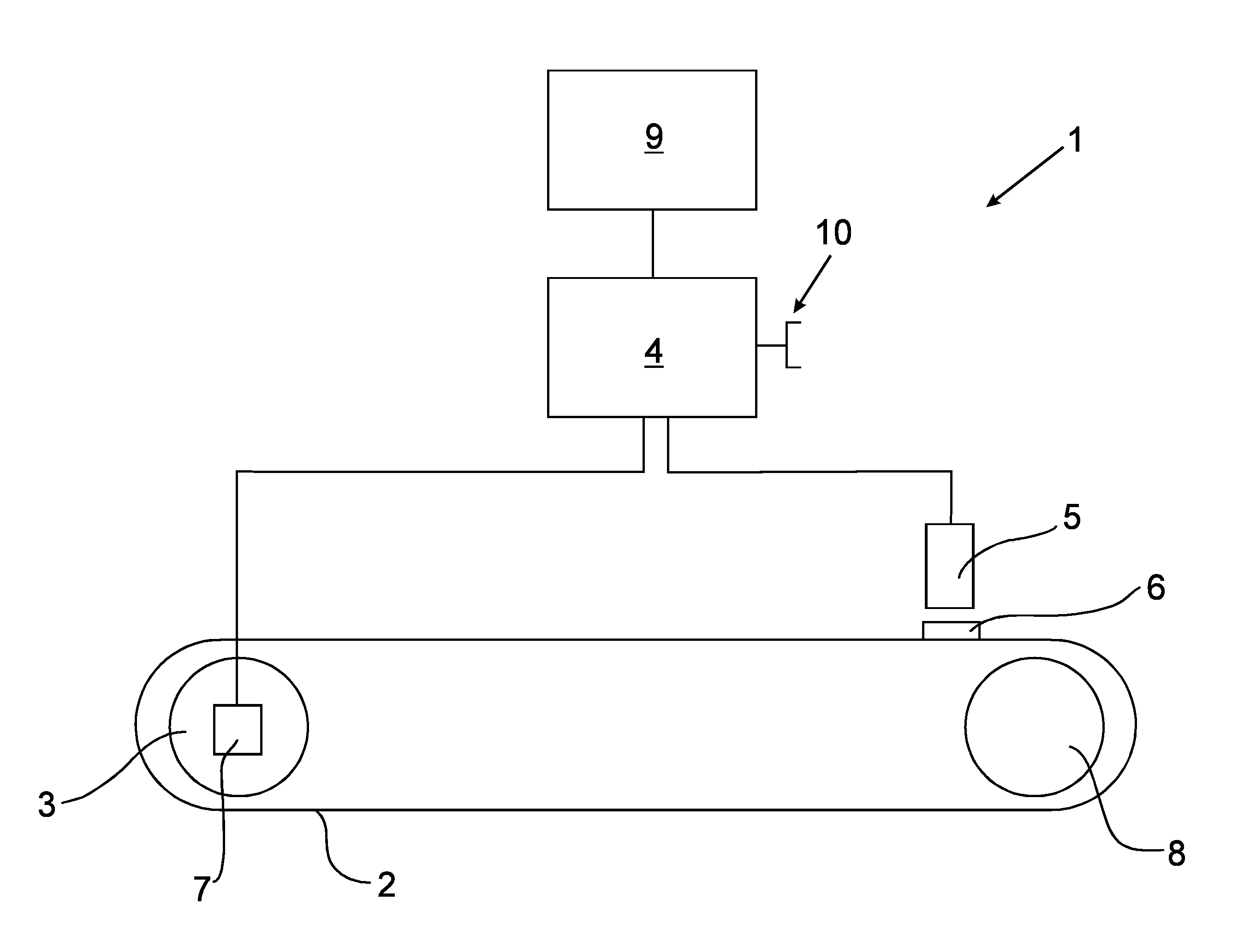
[0048] FIG. 1 A schematic representation of the structure of a device for the transport of containers or multi-packs.
[0049] With a device 1 represented schematically in FIG. 1 for the transport of plastic bottles or multi-packs of bottles, an endless transport belt 2 circulates at one end around a deflection roller 8, and at the other end around a drive roller of a drive unit 3. The drive unit 3 drives the transport belt 2 by means of a servomotor. The servomotor comprises in this situation an incremental transmitter 7 for detecting the respective setting position, and is controlled by a control unit 4, which steplessly regulates the circulating speed of the servomotor and continually receives data from the incremental transmitter 7.
[0050] For further illustration, a switching tag 6 is secured to a surface of the transport belt 2, which can be detected by a sensor 5. The switching tag 6 can of course also be integrated in the interior of the transport belt 2 or in one or more elements of this, and can, for example, be inductively detectable. The sensor 5 is arranged following the drive side of the transport belt 2, at the end of the transport belt 2 facing away from the drive unit 3, in the region of the deflection roller 8, and aligned onto the transport belt 2 in such a way that the switching tag 6 can thereby be detected. The sensor 6 is also connected to the control unit 4, and continuously sends the detection of the switching tag 6 to the control unit 4. As an alternative, this switching tag 6 can, for example, also be a tool or tool part, such as a guide finger and/or shaping finger.
[0051] The control unit 4 is a memory-programmable control device, which comprises a user interface 9 for the device operation and for the output of information. The control unit 4 comprises an interface 10 for programming by means of an external device and/or for the coupling of a plurality of control units 4, for example with an arrangement of several transport belts 2 behind one another or parallel to one another.
[0052] In order to monitor the elongation of the transport belt 2, directly after the installation of a new transport belt 2, at the detection of the switching tag 6 by the sensor 5 in operation, the associated rotation angle value or incremental value of the incremental transmitter 7 is stored in the control unit 4 as a reference value. In subsequent operation of the device 1, regularly or continuously at the detection of the switching tag 6, the rotation angle value or incremental value of the drive unit 3 will again be detected and compared with a reference value. If there is an elongation of the transport belt, the switching tag 6 will reach the sensor 5 somewhat later, as a result of which the associated rotation angle value or incremental value changes. From the difference between both values, the reference value and the rotation angle value presently measured, the elongation of the transport belt 2 can be calculated. The resolution of the measurement in this situation is dependent on the resolution of the incremental transmitter, the number of motor revolutions for one circulation of the transport belt 2, and the length of the transport belt 2.
[0053] In the control unit 4, the elongation or lengthening of the transport belt 2 is monitored, and, when a previously determined limit value is reached, a warning or request for renewal of the transport belt 2 is output on the user interface 9. In particular, the current elongation of the transport belt 2 can be continually reproduced on the user interface 9.
[0054] It is also possible, by means of the control unit 4, for a dynamic speed regulation of the transport belt 2 to be carried out by means of the drive unit 3. For this purpose, likewise the difference between the reference value and the present rotation angle value is detected at the passage of the switching tag 6 past the sensor 5, is taken as the real speed of the transport belt 2 in relation to the circulation speed of the drive unit 3. If there is an elongation of the transport belt 2, the speed of the transport belt 2 slows, with the rotating speed of the drive roller of the drive unit 3 remaining the same. In order to ensure a consistent speed of the transport belt 2, for example in order to keep it in synchrony with a following transport belt, a control arrangement for the drive unit 3 is necessary which is adjusted to the elongation of the transport belt 2. In addition to this, a varying elongation of the transport belt 2 can also occur not only due to wear or ageing, but also due to different loading with objects which are to be transported. Due to the continuous monitoring of the transport belt 2 and the calculation by means of the control unit 4, a dynamic control of the drive unit 3 is possible, and therefore the maintaining of a consistent speed of the transport belt 2, or adjusted to a further transport belt.
REFERENCE NUMBER LIST
[0055] 1 Device for transporting containers or multi-packs
[0056] 2 Transport element
[0057] 3 Drive unit
[0058] 4 Control unit
[0059] 5 Sensor
[0060] 6 Position mark
[0061] 7 Rotation angle detector
[0062] 8 Deflection roller
[0063] 9 User interface
[0064] 10 Interface
* * * * *
D00000
D00001
XML
uspto.report is an independent third-party trademark research tool that is not affiliated, endorsed, or sponsored by the United States Patent and Trademark Office (USPTO) or any other governmental organization. The information provided by uspto.report is based on publicly available data at the time of writing and is intended for informational purposes only.
While we strive to provide accurate and up-to-date information, we do not guarantee the accuracy, completeness, reliability, or suitability of the information displayed on this site. The use of this site is at your own risk. Any reliance you place on such information is therefore strictly at your own risk.
All official trademark data, including owner information, should be verified by visiting the official USPTO website at www.uspto.gov. This site is not intended to replace professional legal advice and should not be used as a substitute for consulting with a legal professional who is knowledgeable about trademark law.