Child-Resistant Large Mouth Container
McNabb; Richard Paul ; et al.
U.S. patent application number 16/301252 was filed with the patent office on 2019-07-11 for child-resistant large mouth container. This patent application is currently assigned to Plastek Industries, Inc.. The applicant listed for this patent is Church & Dwight Co., Inc., Plastek Industries, Inc.. Invention is credited to Timothy C. Dzurik, Frank Edward Lindsay, Albert H. Lund, Richard Paul McNabb, Peter A. Piscopo, Alex S. Szekely, Jonathan Andrew Wharton.
| Application Number | 20190210777 16/301252 |
| Document ID | / |
| Family ID | 60326262 |
| Filed Date | 2019-07-11 |


| United States Patent Application | 20190210777 |
| Kind Code | A1 |
| McNabb; Richard Paul ; et al. | July 11, 2019 |
Child-Resistant Large Mouth Container
Abstract
A container system (20) comprises: a container body (22) having a sidewall (26), a shoulder (32), and an externally threaded neck (34) extending from the shoulder; and a closure (24) having an internally threaded inner sidewall (50) extending from a rim, an outer sidewall (60), and an installed condition with the inner sidewall in threaded engagement with the neck. The outer sidewall has a radially inwardly protruding barb (80) having a ramping surface (82) and a stop surface (84). The container body shoulder has a lug (90) having a ramping surface (92) and a stop surface (94). A first projection (120) protrudes radially outward from the outer sidewall to a first circumferential side of the barb and a second projection (122) protrudes radially outward from the outer sidewall to a second circumferential side of the barb.
| Inventors: | McNabb; Richard Paul; (Solebury, PA) ; Lund; Albert H.; (Westfield, NJ) ; Lindsay; Frank Edward; (Hamilton, NJ) ; Wharton; Jonathan Andrew; (Ewing, NJ) ; Piscopo; Peter A.; (Medford, NJ) ; Szekely; Alex S.; (Jackson, NJ) ; Dzurik; Timothy C.; (Erie, PA) | ||||||||||
| Applicant: |
|
||||||||||
|---|---|---|---|---|---|---|---|---|---|---|---|
| Assignee: | Plastek Industries, Inc. Erie PA Church & Dwight Co., Inc. Princeton NJ |
||||||||||
| Family ID: | 60326262 | ||||||||||
| Appl. No.: | 16/301252 | ||||||||||
| Filed: | May 15, 2017 | ||||||||||
| PCT Filed: | May 15, 2017 | ||||||||||
| PCT NO: | PCT/US2017/032662 | ||||||||||
| 371 Date: | November 13, 2018 |
Related U.S. Patent Documents
| Application Number | Filing Date | Patent Number | ||
|---|---|---|---|---|
| 62337292 | May 16, 2016 | |||
| Current U.S. Class: | 1/1 |
| Current CPC Class: | B65D 50/046 20130101 |
| International Class: | B65D 50/04 20060101 B65D050/04 |
Claims
1. A container system (20) comprising: a container body (22) having: a sidewall (26); a shoulder (32); and an externally threaded neck (34) extending from the shoulder; and a closure (24) having: an internally threaded inner sidewall (50) extending from a rim; an outer sidewall (60); and an installed condition with the inner sidewall in threaded engagement with the neck, wherein: the outer sidewall has a radially inwardly protruding barb (80) having a ramping surface (82) and a stop surface (84); the container body shoulder has a lug (90) having a ramping surface (92) and a stop surface (94); a first projection (120) protrudes radially outward from the outer sidewall to a first circumferential side of the barb; and a second projection (122) protrudes radially outward from the outer sidewall to a second circumferential side of the barb.
2. The system of claim 1 wherein: the closure comprises a circumferential gap between the first projection and the second projection.
3. The system of claim 1 wherein: the lug protrudes upward from the shoulder and radially outward from the neck.
4. The system of claim 1 wherein: the closure has an upper web (70) having a central portion (72) vertically recessed relative to an outer portion (74).
5. The system of claim 4 wherein: a circumferential wall (76) connects the central portion to the outer portion.
6. The system of claim 5 wherein: a plurality of vertical webs (78) span between the central portion and the circumferential wall.
7. The system of claim 1 wherein: the closure has an upper web having an underside bearing a plurality of projections (200) radially overlapping with a rim (36) of the neck.
8. The system of claim 7 wherein: the projections are ramps, each having a surface (202) at the same pitch as a pitch of the internal thread of the inner sidewall.
9. The system of claim 1 wherein: the stop surfaces of the barb and the lug are oriented circumferentially off-radial in a direction that resists their overriding each other.
10. The system of claim 1 wherein: the stop surfaces of the barb and the lug are oriented circumferentially off-radial by at least 10.degree. in a direction that resists their overriding each other.
11. The system of claim 1 wherein: a plurality of vertical webs (79) connect the inner sidewall to the outer sidewall.
12. The system of claim 1 wherein: a radial web (83) connects the first projection and the second projection.
13. A method for using the system of claim 1, the method comprising: squeezing the first projection and the second projection toward each other to radially outwardly shift the barb; and unscrewing the closure while maintaining the squeezing.
Description
CROSS-REFERENCE TO RELATED APPLICATION
[0001] Benefit is claimed of U.S. Patent Application No. 62/337,292, filed May 16, 2016, and entitled "Child-Resistant Large Mouth Container", the disclosure of which is incorporated by reference herein in its entirety as if set forth at length.
BACKGROUND
[0002] The disclosure relates to plastic jars with threaded closures. More particularly, the disclosure relates to child-resistant features for such jars.
[0003] U.S. Pat. No. 5,921,417 to Mull, Jul. 13, 1999, discloses an exemplary existing system.
SUMMARY
[0004] One aspect of the disclosure involves a container system comprising: a container body having a sidewall, a shoulder, and an externally threaded neck extending from the shoulder; and a closure having an internally threaded inner sidewall extending from a rim, an outer sidewall, and an installed condition with the inner sidewall in threaded engagement with the neck. The outer sidewall has a radially inwardly protruding barb having a ramping surface and a stop surface. The container body shoulder has a lug having a ramping surface and a stop surface. A first projection protrudes radially outward from the outer sidewall to a first circumferential side of the barb and a second projection protrudes radially outward from the outer sidewall to a second circumferential side of the barb.
[0005] In one or more embodiments of any of the foregoing embodiments, the closure comprises a circumferential gap between the first projection and the second projection.
[0006] In one or more embodiments of any of the foregoing embodiments, the lug protrudes upward from the shoulder and radially outward from the neck.
[0007] In one or more embodiments of any of the foregoing embodiments, the closure has an upper web having a central portion vertically recessed relative to an outer portion.
[0008] In one or more embodiments of any of the foregoing embodiments, a circumferential wall and connects the central portion to the outer portion.
[0009] In one or more embodiments of any of the foregoing embodiments, a plurality of vertical webs span between the central portion and the circumferential wall.
[0010] In one or more embodiments of any of the foregoing embodiments, the closure has an upper web having an underside bearing a plurality of projections radially overlapping with a rim of the neck.
[0011] In one or more embodiments of any of the foregoing embodiments, the projections are ramps, each having a surface at the same pitch as a pitch of the internal thread of the inner sidewall.
[0012] In one or more embodiments of any of the foregoing embodiments, the stop surfaces are oriented circumferentially off-radial (e.g., at least 10.degree. or an exemplary 10.degree. to 25.degree. or 10.degree. to 20.degree. or about 15.degree.) in a direction that resists their overriding each other.
[0013] In one or more embodiments of any of the foregoing embodiments, wherein: the stop surfaces are oriented circumferentially off-radial by at least 10.degree. in a direction that resists their overriding each other.
[0014] In one or more embodiments of any of the foregoing embodiments, a plurality of vertical webs connect the inner sidewall to the outer sidewall.
[0015] In one or more embodiments of any of the foregoing embodiments, a method for using the system comprises: squeezing the first projection and the second projection toward each other to radially outwardly shift the barb; and unscrewing the closure while maintaining the squeezing.
[0016] The details of one or more embodiments are set forth in the accompanying drawings and the description below. Other features, objects, and advantages will be apparent from the description and drawings, and from the claims.
BRIEF DESCRIPTION OF THE DRAWINGS
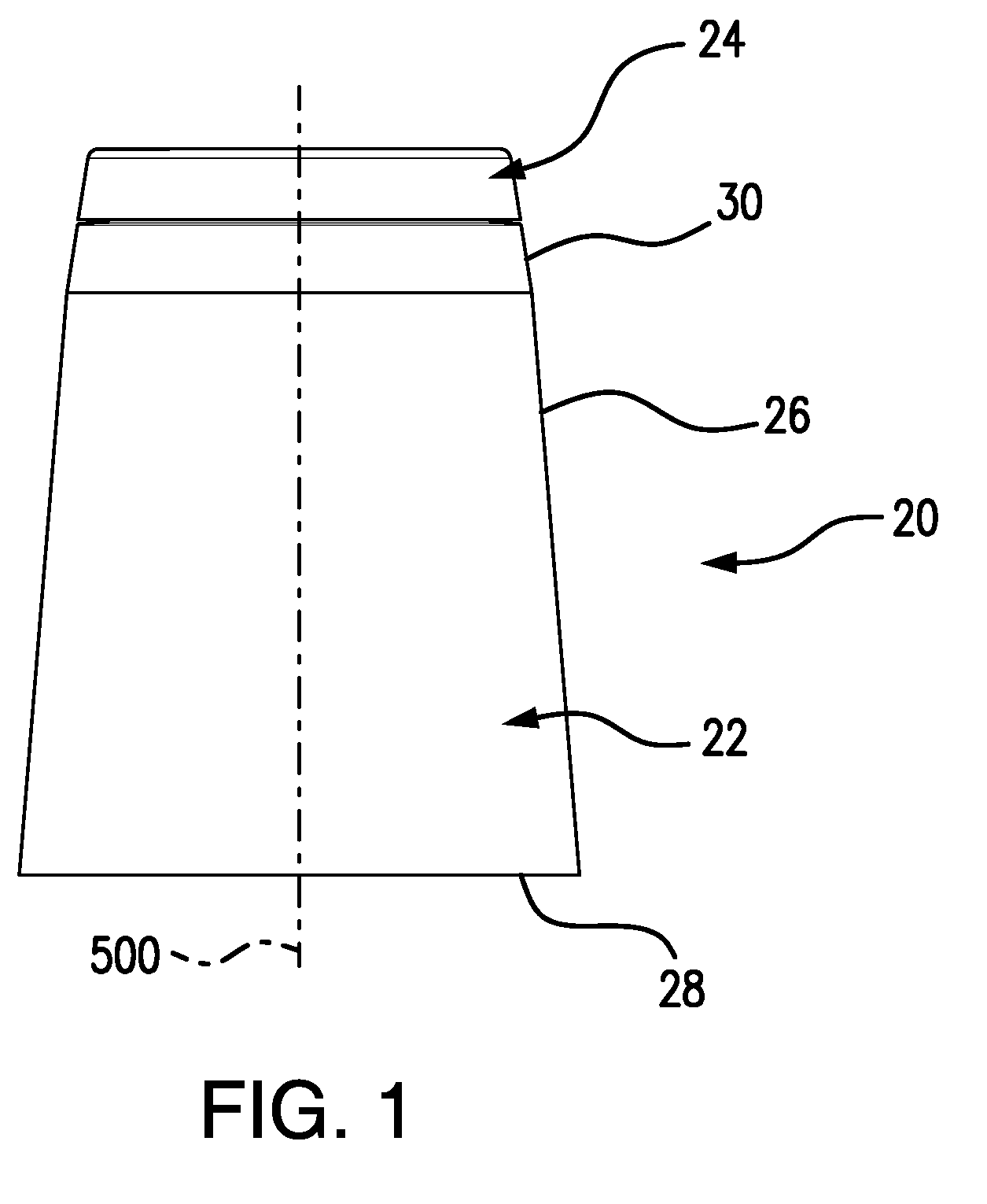
[0017] FIG. 1 is a side view of a container.
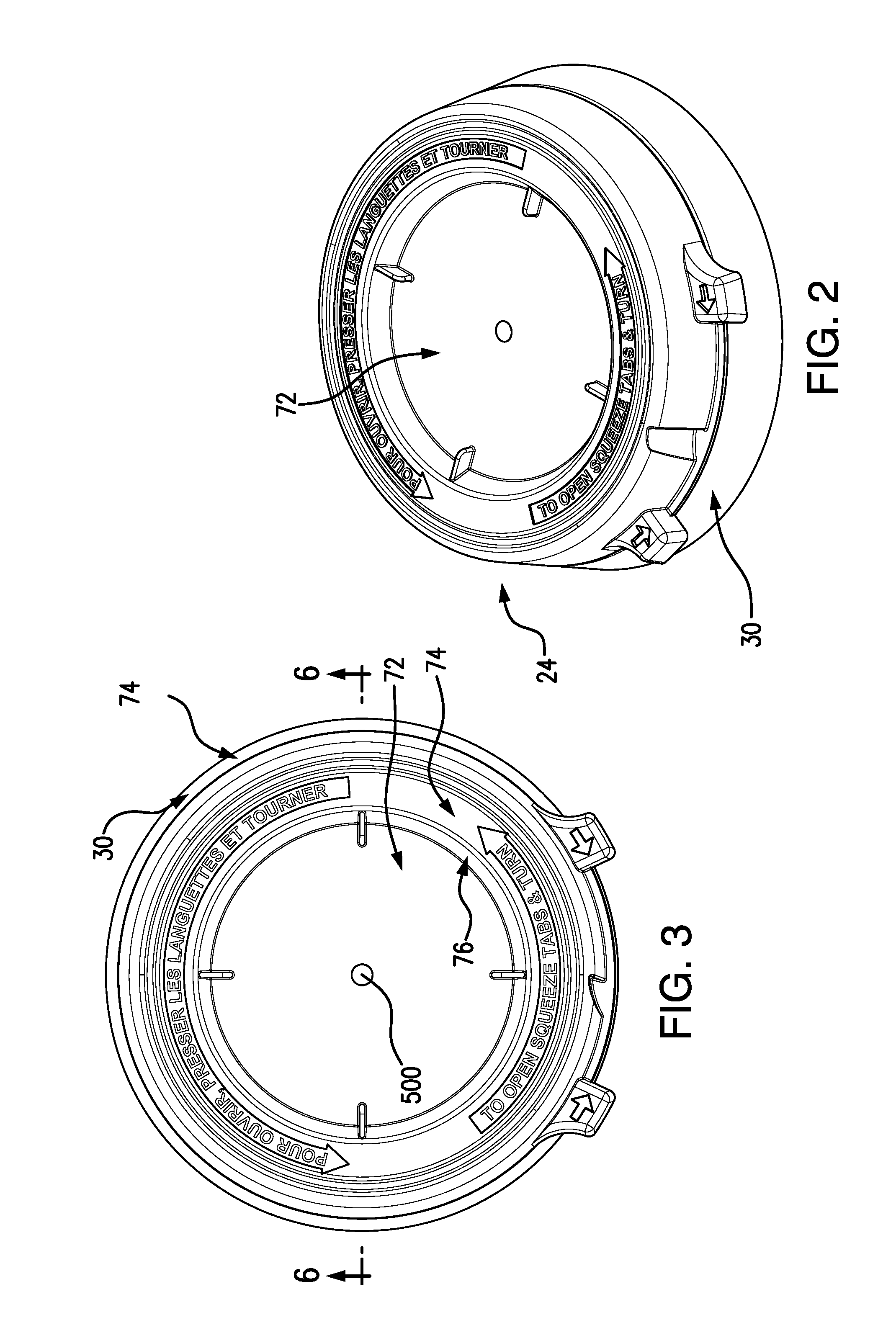
[0018] FIG. 2 is a view of an upper portion of the container (portion below cut away).
[0019] FIG. 3 is a top view of the container upper portion.
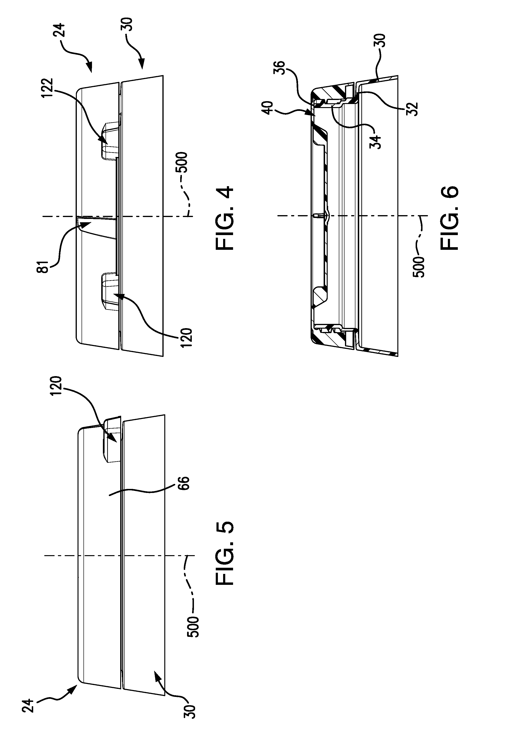
[0020] FIG. 4 is a front view of the container upper portion.
[0021] FIG. 5 is a side view of the container upper portion.
[0022] FIG. 6 is a vertical sectional view of the container upper portion taken along line 6-6 of FIG. 3.
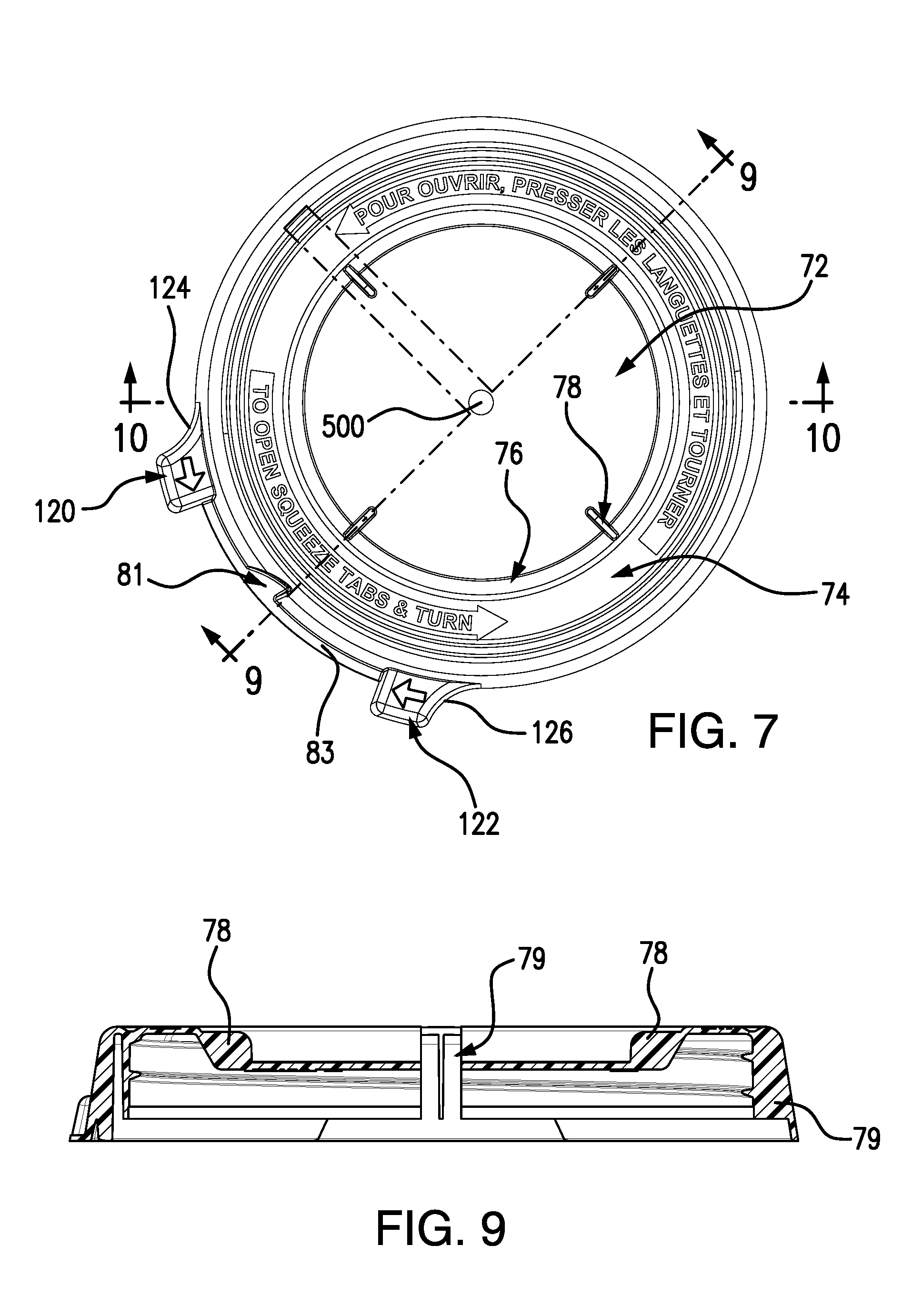
[0023] FIG. 7 is a top view of a closure of the container.
[0024] FIG. 8 is a bottom view of the closure.
[0025] FIG. 9 is a vertical sectional view of the closure taken along line 9-9 of FIG. 7.
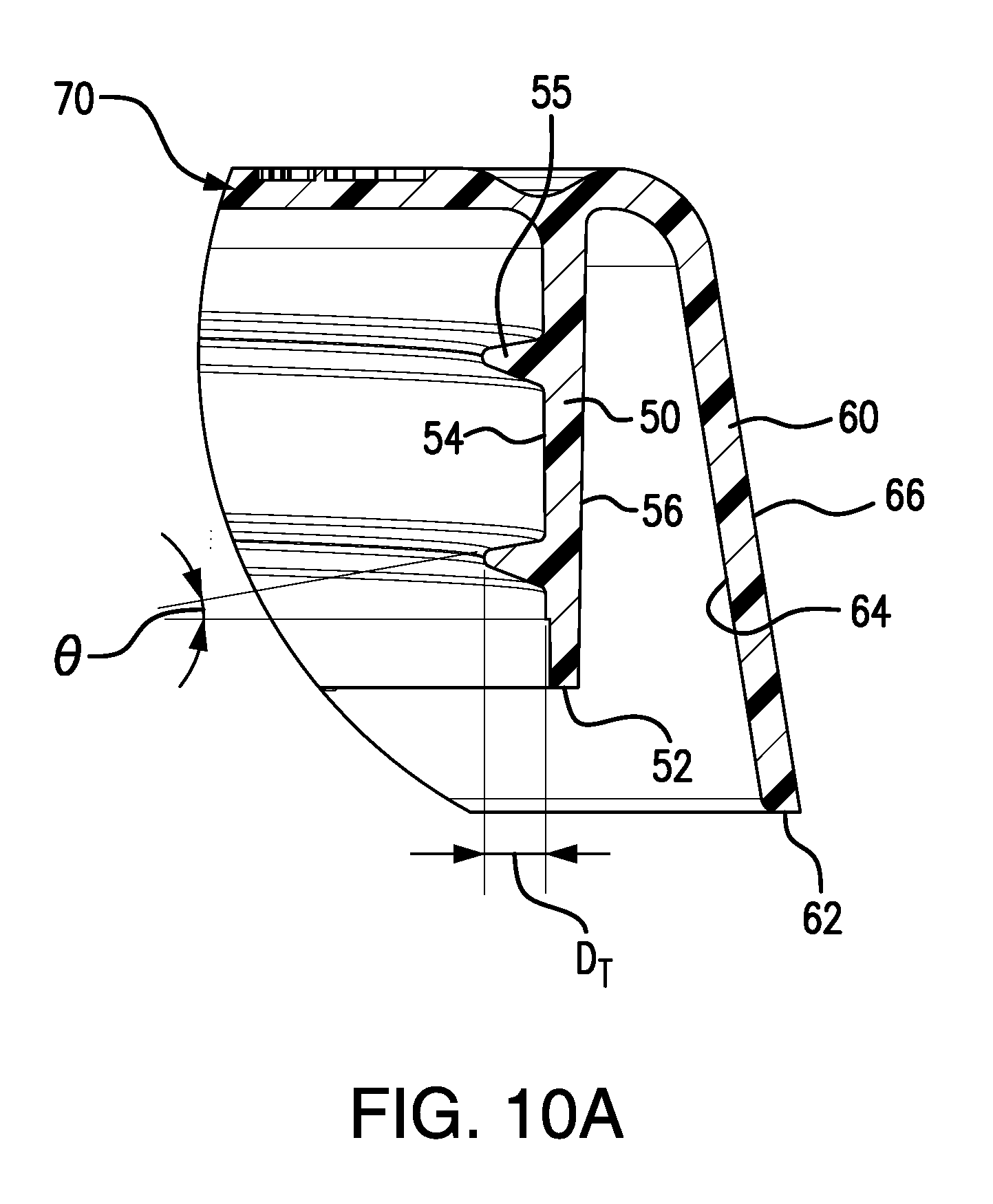
[0026] FIG. 10 is a vertical sectional view of the closure taken along line 10-10 of FIG. 7.
[0027] FIG. 10A is an enlarged view of a portion of the closure of FIG. 10.
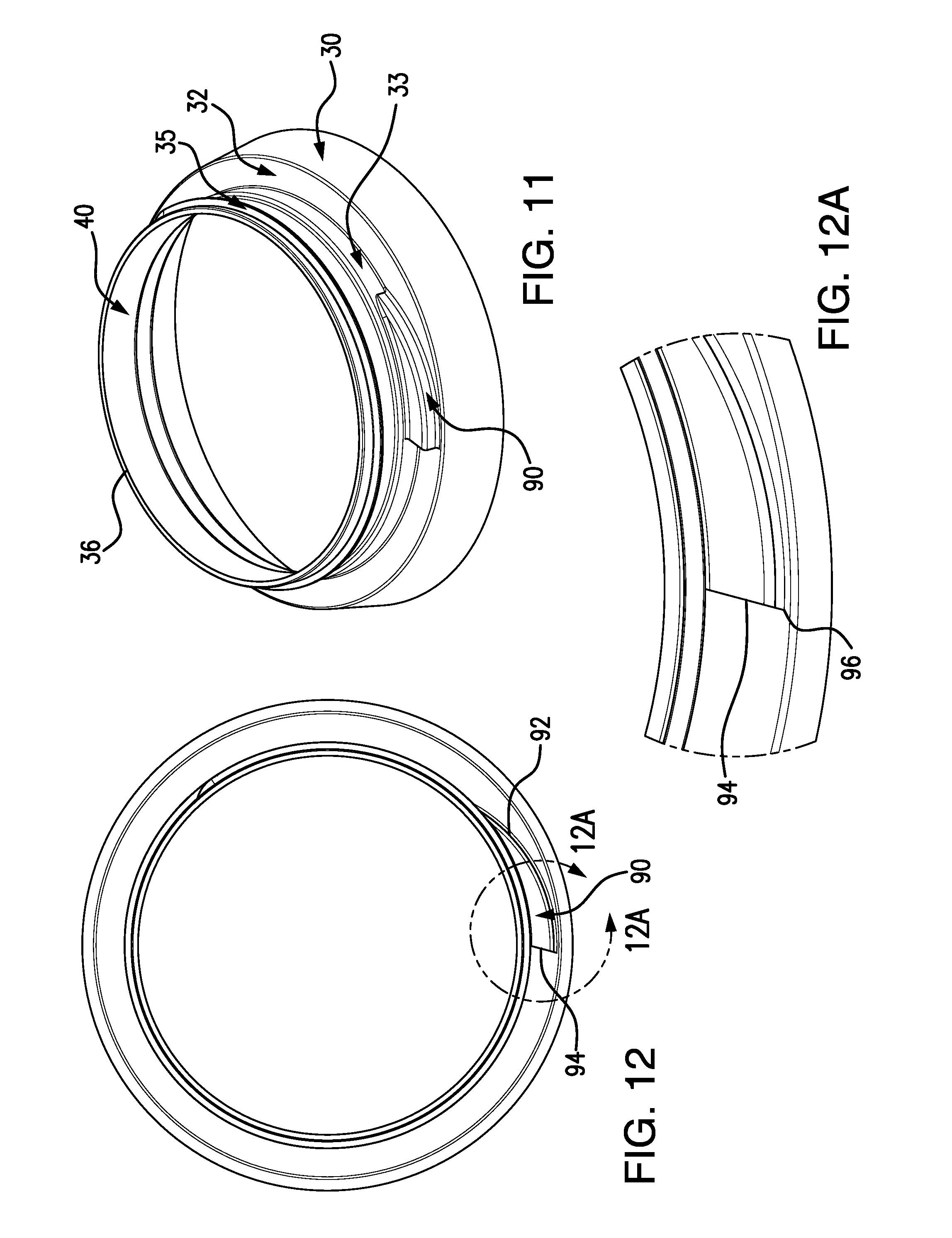
[0028] FIG. 11 is a view of an upper portion of a body of the container.
[0029] FIG. 12 is a top view of the container body upper portion.
[0030] FIG. 12A is an enlarged view of a locking ramp region of the container body.
[0031] FIG. 13 is bottom view of an alternate closure.
[0032] Like reference numbers and designations in the various drawings indicate like elements.
DETAILED DESCRIPTION
[0033] FIG. 1 shows a large-mouth child resistant container 20 comprising a body 22 and a closure 24. The closure 24 is a screw-on closure which may be screwed on and off by rotation about a central longitudinal axis 500 shared by the closure and body when the closure is installed. The exemplary body 22 comprises a sidewall 26 extending upward from a base 28. The sidewall has a tapered upper portion 30 transitioning to a shoulder 32 (FIG. 6). An externally threaded neck 34 (having external thread 35) extends upward from the shoulder to a rim 36. The rim circumscribes an open mouth 40.
[0034] FIGS. 7-11 show the closure 24. The closure comprises an internally threaded inner sidewall 50 (FIG. 10A) extending upward from a lower rim 52 and having a radially inboard surface 54 (bearing the internal thread 55) and an opposite radially outboard surface 56. The closure further comprises an outer sidewall 60 extending from a lower rim 62 and having respective inboard and outboard surfaces 64 and 66. A top web 70 spans the inner sidewall to enclose the container when the closure is installed. FIG. 10 shows the top web 70 as having a central portion 72 vertically recessed relative to an outer portion 74 and connected thereto via an angled circumferential wall 76. A plurality of vertical/radial ribs or webs 78 span between the central portion 72 and circumferential wall 76 to rigidify the circumferential wall. This rigidification plus other rigidifications discussed below help ultimately rigidify the threaded inner wall 50 against being pulled off. FIG. 9 also shows a vertical/radial web 79 between the inner sidewall and the outer sidewall (see also, FIG. 8). In the exemplary embodiment of FIG. 8, these webs 79 are evenly circumferentially spaced with the exception of one missing web adjacent the latching feature 80.
[0035] As is discussed further below, the outer sidewall bears child-resistant features for cooperating with complementary features of the container body. The FIG. 8 underside view shows a child-resistant latching feature 80 extending radially inward from the inboard surface 64 of the outer sidewall 60. In the exemplary embodiment, this is formed as an inward diversion of the outer sidewall 60 associated with a complementary recess 81 (FIG. 7) in the outboard surface 66 of the outer sidewall.
[0036] The complementary feature of the body is a lug 90 (FIG. 11). The exemplary lug 90 extends upward from an upper surface of the shoulder 32 and radially outward from an outboard surface of a lower portion 33 of the neck below the external thread 35. As with the feature 80, the exemplary feature 90 is formed as a protrusion associated with a complementary internal recess to maintain a generally constant wall thickness. This, for example, may be an artifact of injection blow molding or other blow molding process forming the features. Each of the features 80 and 90 has a respective ramping surface 82, 92 and stop surface 84, 94. The exemplary ramping surfaces are essentially vertical and of slightly off-circumferential orientation. In the exemplary embodiment, both are convex arcs. The arcs are oriented so that during an installing rotation, the ramping surfaces contact each other as the feature 80 is rotated past the feature 90. A ramping action radially outwardly deforms the outer sidewall 60 at the feature 80 locally. Upon further rotation, eventually the ramping surfaces will pass out of engagement (e.g., when respective apexes 86, 96 pass each other). At this point, the outer sidewall will snap back radially to a relaxed condition.
[0037] Once the closure is fully installed, an unscrewing rotation will tend to bring the stop surfaces 84 and 94 into contact with each other. The stop surfaces are oriented generally vertically and slightly circumferentially off-radial (e.g., at least 10.degree. or an exemplary 10.degree. to 25.degree. or 10.degree. to 20.degree. or about 15.degree.) in a direction that resists their overriding each other in attempted unscrewing. Thus, further unscrewing torque will tend to drive the outer sidewall locally inward to maintain engagement between the features 80 and 90 and prevent unscrewing rotation.
[0038] To facilitate unscrewing rotation, the user must locally outwardly deform the closure body outer sidewall 60 at the feature 80 so as to shift it sufficiently radially outward to override the feature 90. This is done by the provision of a pair of finger actuatable tabs (radial outward projections) 120 and 122 (FIG. 7) on two opposite circumferential sides of the feature 80. The tabs have circumferentially outboard surfaces 124 and 126. The user may pinch the tabs by replacing a thumb on one of these surfaces and a forefinger on the other and squeezing those fingers toward each other. FIG. 7 shows a radial web 83 protruding radially outward along an arc between the tabs. The addition of the web increases required squeezing force to allow the outward shift of the feature 80. This exemplary web extends outward across the recess 81. An exemplary web protrudes by at least about 0.05 inch (e.g., 0.05 inch to 0.15 inch) along the intact portions of the sidewall (away from the recess 81). The amount of protrusion may circumferentially vary. As show, a much greater radial extent is shown at the recess 81.
[0039] An additional feature which may be implemented independently of the child-resistant features is a ventilation feature. The exemplary ventilation feature vents the container interior even when the closure is fully screwed on. This may be relevant when the particular contents of the container have a tendency to outgas or react and produce gas that must be vented to avoid pressurizing the container. The exemplary pressure relief features comprises a plurality of ramps 200 (four shown in FIG. 13) on the underside of the closure top web 70 at a radial position at least partially overlapping the rim of the container body. The exemplary ramps 200 have a first surface 202 and a second surface 204 as well as an ID surface 206 and an OD surface 208. The first surface 202 is at a pitch corresponding to the thread pitch. This allows the ramps to be released from a mold portion that molds the interior of the closure including the threads. The closure is simply unscrewed from this mold portion.
[0040] The container may be made using otherwise conventional or yet-developed materials and techniques. Exemplary closure manufacture is by injection molding and body manufacture by blow molding. Exemplary closure material is polypropylene. Exemplary body material is high density polyethylene (HDPE).
[0041] One variation on conventional techniques involves using a thread of greater than standard depth DT (FIG. 10A) on both neck and closure. The greater radial engagement between the two threads allows positive retention of the closure while allowing the closure to be light and inexpensive to manufacture. Exemplary depth with an approximately 3 inch mouth diameter is in excess of 0.060 inch or in excess of 0.070 inch and up to about 0.100 inch or 0.09 inch with an example of 0.70 inch to 0.80 inch or 0.76 inch. This may be contrasted with a standard thread of 0.046 inch. The extra depth is provided by making the angle of the non-bearing face of the thread closer to radial. This depth is about 50% greater (e.g., at least 30% or 30% to 60% greater) than the SP-400 Voluntary Standard SP400, International Society of Beverage Technologists drawing 1165379-1 1999 Mar. 10, the disclosure of which is incorporated by reference herein as if set forth at length.
[0042] The use of "first", "second", and the like in the description and following claims is for differentiation within the claim only and does not necessarily indicate relative or absolute importance or temporal order. Similarly, the identification in a claim of one element as "first" (or the like) does not preclude such "first" element from identifying an element that is referred to as "second" (or the like) in another claim or in the description.
[0043] Where a measure is given in English units followed by a parenthetical containing SI or other units, the parenthetical's units are a conversion and should not imply a degree of precision not found in the English units.
[0044] One or more embodiments have been described. Nevertheless, it will be understood that various modifications may be made. For example, when applied to an existing basic system, details of such configuration or its associated use may influence details of particular implementations. Accordingly, other embodiments are within the scope of the following claims.
* * * * *
D00000
D00001
D00002
D00003
D00004
D00005
D00006
D00007
D00008
XML
uspto.report is an independent third-party trademark research tool that is not affiliated, endorsed, or sponsored by the United States Patent and Trademark Office (USPTO) or any other governmental organization. The information provided by uspto.report is based on publicly available data at the time of writing and is intended for informational purposes only.
While we strive to provide accurate and up-to-date information, we do not guarantee the accuracy, completeness, reliability, or suitability of the information displayed on this site. The use of this site is at your own risk. Any reliance you place on such information is therefore strictly at your own risk.
All official trademark data, including owner information, should be verified by visiting the official USPTO website at www.uspto.gov. This site is not intended to replace professional legal advice and should not be used as a substitute for consulting with a legal professional who is knowledgeable about trademark law.