Convenient Lid
HUANG; Liming
U.S. patent application number 15/939272 was filed with the patent office on 2019-07-11 for convenient lid. The applicant listed for this patent is Liming HUANG. Invention is credited to Liming HUANG.
| Application Number | 20190210773 15/939272 |
| Document ID | / |
| Family ID | 59342567 |
| Filed Date | 2019-07-11 |

| United States Patent Application | 20190210773 |
| Kind Code | A1 |
| HUANG; Liming | July 11, 2019 |
Convenient Lid
Abstract
The disclosure relates to a convenient lid comprising a housing, a lid opening, a press plate, a button, an insertion plate, a guide plate and a threaded body, the lid opening and the threaded body being provided on the lower part of the housing, the side of the lid being provided with a concave cavity, a fixing body and a guide column being provided in the concave cavity, a switch device and a security device being provided on the fixing body and the guide column, a guide plate, an insertion plate and a press plate being provided inside the lid, a concave ring and a guide strip being provided on the outside of the lid opening, a convex ring, a guide slot and a latch being provided on the inner side of the threaded body, ribs and threads being provided on the outer side of the threaded body.
| Inventors: | HUANG; Liming; (Shenzhen, CN) | ||||||||||
| Applicant: |
|
||||||||||
|---|---|---|---|---|---|---|---|---|---|---|---|
| Family ID: | 59342567 | ||||||||||
| Appl. No.: | 15/939272 | ||||||||||
| Filed: | March 28, 2018 |
Related U.S. Patent Documents
| Application Number | Filing Date | Patent Number | ||
|---|---|---|---|---|
| PCT/CN2018/072124 | Jan 10, 2018 | |||
| 15939272 | ||||
| Current U.S. Class: | 1/1 |
| Current CPC Class: | B65D 45/025 20130101; A45F 3/16 20130101; B65D 47/249 20130101; B65D 43/26 20130101; A47G 19/2272 20130101; B65D 47/20 20130101; B65D 47/0823 20130101 |
| International Class: | B65D 45/02 20060101 B65D045/02; B65D 43/26 20060101 B65D043/26 |
Claims
1. A convenient lid, comprising: a housing; a lid opening; a press plate; a button; an insertion plate; a guide plate; a threaded body; a water outlet; and a press buckle; the press buckle being provided on the upper part of the housing, the press buckle being provided with a buckle foot, the lid opening and the threaded body being provided on the lower part of the housing, the side of the lid being provided with a concave cavity, a fixing body and a guide column being provided in the concave cavity, a switch device and a security device being provided on the fixing body and the guide column, the switch device being composed of a press plate and a movable shaft, the security device being composed of the button and the movable plate and being provided in the press plate, a guide plate, an insertion plate and a press plate being provided inside the lid, the press buckle being provided above a vent, characterized by: a concave ring and a guide strip being provided on the outside of the lid opening, a convex ring, a guide slot and a latch being provided on the inner side of the threaded body, the movable shaft being provided with a retaining ring at the front end, a top ring and a slot column in the middle, and a seal block, a spring and a movable plate in the rear portion, the seal block being provided with a seal ring, a rubber ring being provided between the top ring and the slot column, a spring being provided on the slot column, the top ring and the retaining ring being provided on the guide plate, the guide plate being provided with a long slot, an insertion body being provided within the long slot, the guide plate being provided within the housing, a concave cavity being provided on the press plate, the button being provided on the concave cavity, the blocking plate, the fixing column and the square hole being provided on the movable plate, the spring being provided on the fixing column, a no-slit strip and a square body being provided on the button, the square body being connected to the square hole on the movable plate.
2. The convenient lid according to claim 1, wherein ribs and threads are provided on an outer side of the threaded body.
3. The convenient lid according to claim 1, wherein the press buckle is provided with a shaft hole at one end and a card slot at the other end.
4. The convenient lid according to claim 1, wherein the insertion plate is provided with a circular hole at one end, an insertion body at the other end, and a rotating shaft in the middle, the rotating shaft being connected with the shaft hole of the press buckle.
5. The convenient lid according to claim 1, wherein the insertion body is connected with the guide plate within the lid.
6. The convenient lid according to claim 1, wherein the insertion plate is connected with the top plate, the top plate is provided with a soft edge and a pin, the pin is connected with the circular hole on the insertion plate, the soft edge is provided on the back of the water outlet.
7. The convenient lid according to claim 1, wherein the card slot on the buckle plate is fastened on the latch of the lid.
Description
CROSS-REFERENCE TO THE RELATED APPLICATION
[0001] The present application is a continuation of International Patent Application No. PCT/CN2018/072124, with an international filing date of Jan. 10, 2018 and entitled "Convenient Lid," the entire contents of which is incorporated herein by reference.
TECHNICAL FIELD
[0002] The present disclosure relates to an accessory for tea sets, and in particular, to a convenient lid for various thermal insulated containers.
BACKGROUND
[0003] With the development of society, economic prosperity, and improvement of living standards, people work, surfing the Internet, and chat, with increasingly demands for quality of life. Leisure travel and outdoor sports are increasing. Drinking tea is also an indispensable part of people's lives. Therefore, a lid for a thermal insulated container, with a security switch, is popular among people, such as a lid patent with the application No. 201320246931.0, which is anti-fragile and leak-proof. However, during tea drinking, the lid requires both hands to uncover, that is, people first press the security switch and then uncover the lid to drink tea, which cannot meet the different needs of those who live fast or busy.
SUMMARY
[0004] In order to overcome the deficiencies of the above problems, the present disclosure provides a convenient lid. With the convenient lid, people need to use only one hand to hold the thermal insulated container, press down the press plate on the lid with the thumb, slide the button downwards, and then uncover the lid switch, to drink tea. After the thumb moves away, the lid switch will automatically lock, and also the switch can be automatically secured. In order to firmly bond the container and the threaded body without leak, a concave ring and a guide strip are provided in the lid opening, and a convex ring and a guide slot are provided on the threaded body, and the threaded body is pressed into the lid opening using the principle of thermal expansion and contraction of plastic. In order to open the security device and the switch with one hand, the security device is placed in the switch device. In order to facilitate the cleaning of the dirt on the lid, all the accessories in the lid are placed on the insertion plate. To facilitate disassembly, the insertion plate and the guide plate are combined in a movable manner, which is convenient, clean and leak-proof.
[0005] The technical solution adopted by the present disclosure to solve the technical problems is: a convenient lid, comprising a housing, a lid opening, a press plate, a button, an insertion plate, a guide plate and a threaded body, a water outlet and a press buckle being provided on the upper part of the housing, the press buckle being provided with a buckle foot, the lid opening and the threaded body being provided on the lower part of the housing, the side of the lid being provided with a concave cavity, a fixing body and a guide column being provided in the concave cavity, a switch device and a security device being provided on the fixing body and the guide column, a guide plate, an insertion plate and a press plate being provided inside the lid, a concave ring and a guide strip being provided on the outside of the lid opening, a convex ring, a guide slot and a latch being provided on the inner side of the threaded body, ribs and threads being provided on the outer side of the threaded body; the press buckle being provided above the vent; the switch device being composed of a press plate and a movable shaft, a retaining ring being provided at the front end of the movable shaft, a top ring and a slot column being provided in the middle of the movable shaft, and a seal block, a spring and a movable plate being provided at the rear portion of the movable shaft, the seal block being provided with a seal ring; a rubber ring being provided between the top ring and the slot column, wherein the rubber ring can be installed or removed without the need for tools and the switch device can be directly assembled or disassembled by hand; a spring being provided on the slot column; the top ring and the retaining ring being provided on the guide plate; the guide plate being provided with a long slot; an guide body being provided within the long slot; the guide plate being provided in the housing; the security device being composed of a button and a movable plate and being provided in the press plate; a concave cavity being provided on the press plate, a button being provided on the concave cavity, and a blocking plate, a fixing column and a square hole being provided on the movable plate; a spring being provided on the fixing column; the button being provided with a non-slip strip and a square body, the square body being connected with the square hole on the movable plate, one end of the buckle plate being provided with a shaft hole and the other end being provided with a card slot; the insertion plate being provided with a circular hole at one end thereof, an insertion body at the other end of the insertion plate, and a rotating shaft in the middle of the insertion plate, the rotating shaft being connected with the shaft hole of the buckle plate, the insertion body being connected with the guide plate inside the lid, and the insertion plate being connected with the top plate; the top plate being provided with a soft edge and a pin, the pin being connected with the circular hole on the insertion plate, the soft edge being provided on the back of the water outlet, and the card slot on the buckle plate being fastened on the latch of the lid.
[0006] The beneficial effect of the present disclosure is that with the convenient lid, people only need to use one hand to hold the thermal insulated container, press down the press plate on the lid with the thumb, slide the button downwards, and then uncover the lid switch to drink tea. After the thumb moves away, the lid switch will automatically lock, and also the switch can be automatically secured. In order to firmly bond the container and threaded body without leak, a concave ring and a guide strip are provided in the lid opening, and a convex ring and a guide slot are provided on the threaded body, and the threaded body is pressed into the lid opening using the principle of thermal expansion and contraction of plastic. In order to open the security device and the switch with one hand, the security device is placed in the switch device. In order to facilitate the cleaning of the dirt on the lid, all the accessories in the lid are placed on the insertion plate. To facilitate disassembly, the insertion plate and the guide plate are combined in a movable manner, which is convenient, clean and leak-proof.
BRIEF DESCRIPTION OF THE DRAWINGS
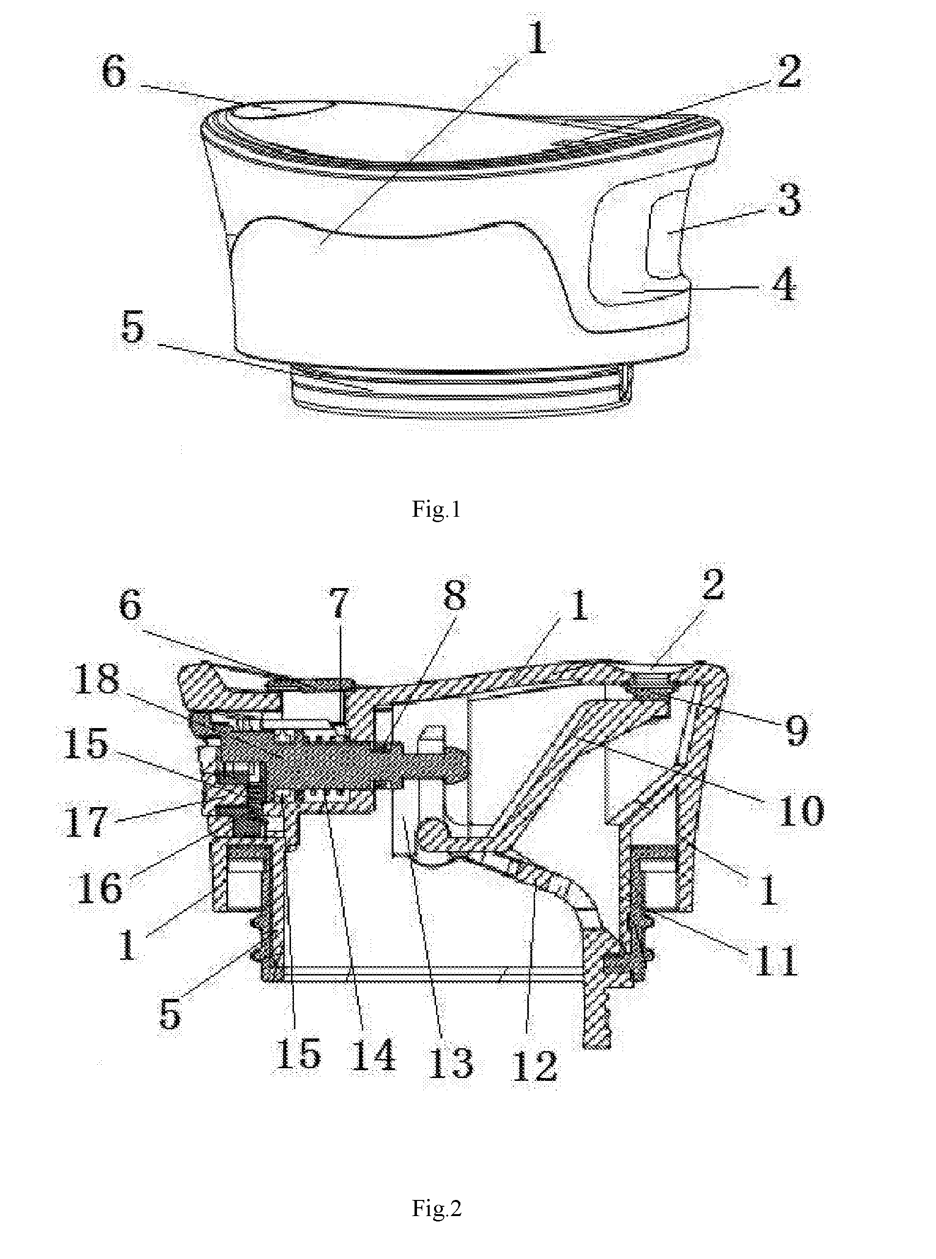
[0007] FIG. 1 is a schematic structural view of the present disclosure.
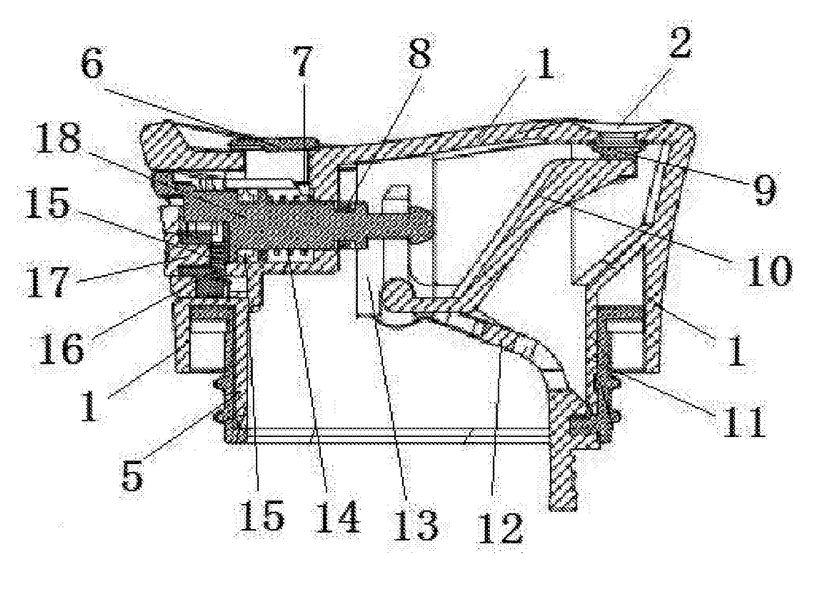
[0008] FIG. 2 is a sectional view of the present disclosure.
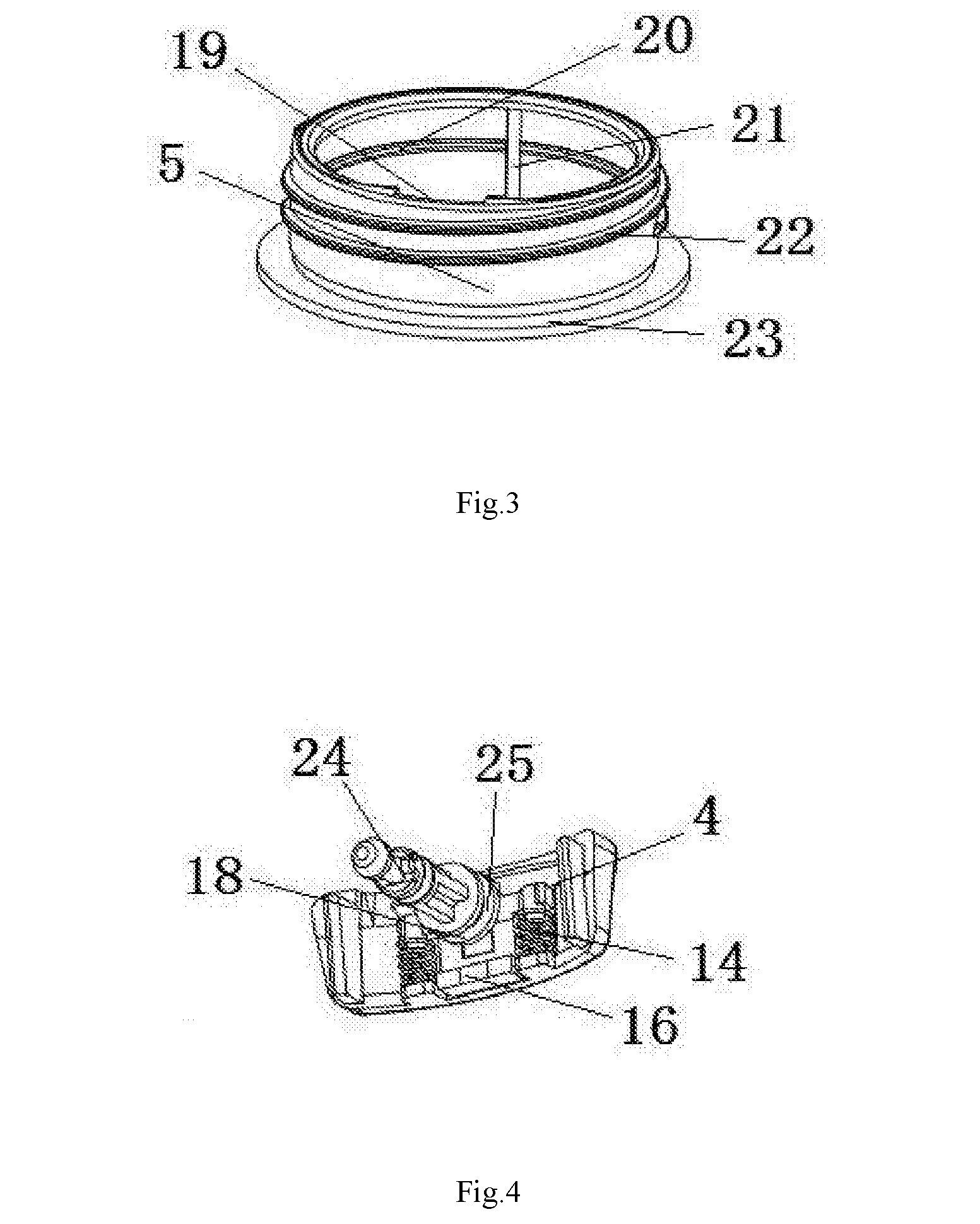
[0009] FIG. 3 is a schematic structural view of a threaded body in the present disclosure.
[0010] FIG. 4 is a schematic structural view of a switch device in the present disclosure.
[0011] FIG. 5 is a schematic structural view of a press buckle in the present disclosure.
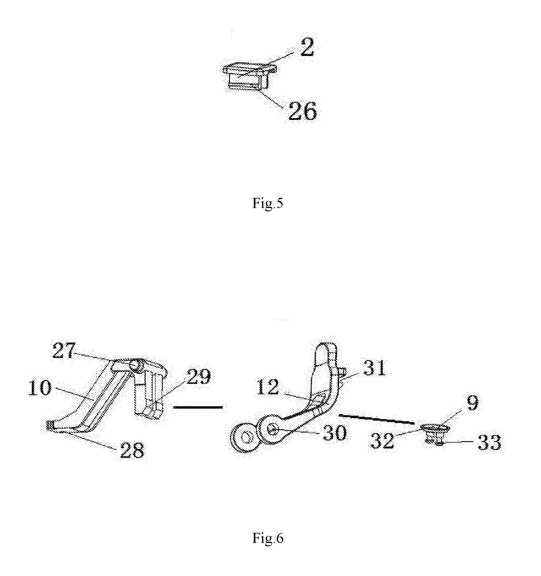
[0012] FIG. 6 is a schematic structural view of an insertion body and a buckle plate in the present disclosure.
[0013] FIG. 7 is a schematic structural view of the disassembled present disclosure.
[0014] FIG. 8 is a schematic structural view of the switch device and the security device in the present disclosure.
[0015] Reference signs in the drawings: 1, housing; 2, press buckle; 3, button; 4, press plate; 5, threaded body; 6, water outlet; 7, vent; 8, rubber ring; 9, top plate; 10, insertion plate; 11, lid opening; 12, buckle plate; 13, guide plate; 14, spring; 15, seal ring; 16, movable plate; 17, security device; 18, switch device; 19, latch; 20, convex ring; 21, guide slot; 22, thread; 23, rib; 24, movable shaft; 25, sealing block; 26, buckle foot; 27, rotating shaft; 28, circular hole; 29, insertion body; 30, shaft hole; 31, card slot; 32, soft edge; 33, pin; 34, concave cavity; 35, guide column; 36, fixing body; 37, square hole; 38, fixing column; 39, blocking plate; 40, retaining ring; 41, top ring; 42, slot column; 43, anti-slip strip; 44, square body.
DETAILED DESCRIPTION
[0016] The following examples are intended to illustrate the present disclosure but are not intended to limit the scope of the present disclosure.
[0017] In FIG. 1 and FIG. 2, a housing 1 is provided, on the upper part thereof, with a water outlet 6 and a press buckle 2. The press buckle 2 is connected to a buckle foot. The lower part of the housing 1 is connected to a lid opening and has a threaded body 5 provided thereon. The side of the lid has a concave cavity in which a fixing body and a guide column are installed. A switch device 18 and a security device 17 are installed on the fixing body and the guide column. A guide plate 13, an insertion plate 10 and a buckle plate 12 are installed in the lid. A concave ring and a guide strip are provided on the outer side of the lid opening 11. A convex ring, a guide slot and a latch are provided on the inner side of the threaded body 5, ribs and threads are provided on the outer side of the threaded body 5, and the press buckle 2 is installed above the vent 7. The switch device 18 is composed of a press plate 4 and a movable shaft. The movable shaft is provided with a retaining ring at the front end, a top ring and a slot column in the middle, and a seal block, a spring and a movable plate in the rear portion. A seal ring 15 is mounted on the seal block, and a rubber ring 8 is installed between the top ring and the slot column. The rubber ring can be installed or removed without the need for tools and the switch device can be directly assembled or disassembled by hand. A spring 14 is installed on the slot column. The top ring and the retaining ring are provided on the guide plate 13. The guide plate 13 is connected to the housing 1. A long slot is provided on the guide plate. An insertion body 10 is installed within the long slot. The security device 17 is composed of a button 3 and a movable plate 16 and is provided in the press plate 4. A concave cavity is provided on the press plate 4. A button 3 is provided on the concave cavity. A blocking plate, a fixing column and a square hole are provided on the movable plate 16. A spring 14 is provided on the fixing column. The button 3 is provided with a non-slip strip and a square body, and the square body is connected with the square hole on the movable plate. One end of the buckle plate 12 is provided with a shaft hole and the other end is provided with a card slot. The insertion plate 10 is provided with a circular hole at one end thereof, an insertion body at the other end, and a rotating shaft in the middle, the rotating shaft is connected with the shaft hole of the buckle plate, the insertion body is connected with the guide plate 13 inside the lid, and the insertion plate 10 is connected with the top plate 9. The top plate 9 is provided with a soft edge and a pin, the pin is connected with the circular hole on the insertion plate, the soft edge is provided on the back of the water outlet 6, and the card slot 31 on the buckle plate 12 is fastened on the latch of the lid. When people need to drink tea, people just use one hand to pick up the lid of the thermal insulated container, press the button on the lid with the thumb and slide it downwards at the same time, the top plate inside the lid will leave the back of the water outlet, tea will flow out of the water outlet, and people can drink the required tea.
[0018] In FIG. 3, the convex cavity 20, the guide slot 21, and the latch 19 are provided on the inner side of the threaded body 5, and the rib 23 and the thread 22 are provided on the outer side of the threaded body 5.
[0019] In FIG. 4, the switch device 18 is composed of a press plate 4 and a movable shaft 24. The movable shaft 24 is provided with a retaining ring on the front end thereof, a top ring and a slot column provided on the middle, and a sealing block 25 provided onto and a spring 14 and a movable plate 16 mounted on the rear portion of the movable shaft 24.
[0020] In FIG. 5, a buckle foot 26 is connected to the press buckle 2.
[0021] In FIG. 6, the buckle plate 12 is provided with a shaft hole 30 at one end and a slot 31 at the other end. The insertion plate 10 is provided with a circular hole 28 at one end, an insertion body 29 connected to the other end, and a rotating shaft 27 connected to the middle. The rotating shaft 27 is connected to the shaft hole 30 of the buckle plate, the insert body 29 is connected with the guide plate inside the lid, the insertion plate 10 is connected with the top plate 9, and the soft edge 32 and the pin 33 are provided on the top plate 9.
[0022] In FIG. 7, a concave cavity 34 is provided on the side of the lid, a fixing body 36 and a guide column 35 are installed in the concave cavity 34, and a guide plate 13, a water outlet 6, and a latch 19 are installed in the lid.
[0023] In FIG. 8, the switch device 18 consists of a press plate 4 and a movable shaft 24. The movable shaft 24 is provided with a retaining ring 40 provided onto the front end thereof, a top ring 41 and a slot column 42 provided onto the middle thereof, and a seal block provided onto and a spring 14 and a movable plate 16 installed on the rear portion thereof. A seal ring 15 is mounted on the seal block. A rubber ring 8 is installed between the top ring 41 and the slot column 42. To install or remove the rubber ring, people can directly assemble or disassemble the switch device with hands without using a tool. The spring 14 is mounted on the slot column 42, and the top ring 41 and the retaining ring 40 are mounted on the guide plate. The security device which is composed of a button 3 and a movable plate 16 is installed in the press plate 4. A concave cavity 34 is provided onto the press plate 4, and the button 3 is mounted on the concave cavity 34. A block plate 39, a fixing column 38 and a square hole 37 are provided onto the movable plate 16. A spring 14 is mounted on the fixing column 38. A non-slip strip 43 and a square body 44 are provided on the button 3, and the square body 44 is connected to the square hole 37 on the movable plate.
[0024] Although the present disclosure has been described above in detail with general description and specific embodiments, it is obvious to those skilled in the art that some modifications or improvements can be made on the basis of the present disclosure. Therefore, these modifications or improvements made without departing from the spirit of the present disclosure all fall within the protection scope of the present disclosure.
* * * * *
D00000
D00001
D00002
D00003
D00004
XML
uspto.report is an independent third-party trademark research tool that is not affiliated, endorsed, or sponsored by the United States Patent and Trademark Office (USPTO) or any other governmental organization. The information provided by uspto.report is based on publicly available data at the time of writing and is intended for informational purposes only.
While we strive to provide accurate and up-to-date information, we do not guarantee the accuracy, completeness, reliability, or suitability of the information displayed on this site. The use of this site is at your own risk. Any reliance you place on such information is therefore strictly at your own risk.
All official trademark data, including owner information, should be verified by visiting the official USPTO website at www.uspto.gov. This site is not intended to replace professional legal advice and should not be used as a substitute for consulting with a legal professional who is knowledgeable about trademark law.