Polishing Or Grinding Pad With Multilayer Reinforcement
Tchakarov; Tchavdar V.
U.S. patent application number 15/867908 was filed with the patent office on 2019-07-11 for polishing or grinding pad with multilayer reinforcement. This patent application is currently assigned to Diamond Tool Supply, Inc.. The applicant listed for this patent is Diamond Tool Supply, Inc.. Invention is credited to Tchavdar V. Tchakarov.
| Application Number | 20190210192 15/867908 |
| Document ID | / |
| Family ID | 65234718 |
| Filed Date | 2019-07-11 |


View All Diagrams
| United States Patent Application | 20190210192 |
| Kind Code | A1 |
| Tchakarov; Tchavdar V. | July 11, 2019 |
POLISHING OR GRINDING PAD WITH MULTILAYER REINFORCEMENT
Abstract
A polishing or grinding pad with a multilayer reinforcement is provided. In one aspect, a floor polishing or grinding pad assembly employs a flexible pad, at least two reinforcement layers or rings with different characteristics, and multiple floor-contacting tools such as abrasive disks. In another aspect, a workpiece polishing or grinding pad assembly includes a flexible and rotatable pad, a polymeric reinforcement layer coupled to the pad and a metallic reinforcement layer to which are coupled abrasive tools. In yet another aspect, a floor-facing reinforcement is more flexible than a pad-facing reinforcement which is more rigid.
| Inventors: | Tchakarov; Tchavdar V.; (Monroe, MI) | ||||||||||
| Applicant: |
|
||||||||||
|---|---|---|---|---|---|---|---|---|---|---|---|
| Assignee: | Diamond Tool Supply, Inc. Monroe MI |
||||||||||
| Family ID: | 65234718 | ||||||||||
| Appl. No.: | 15/867908 | ||||||||||
| Filed: | January 11, 2018 |
| Current U.S. Class: | 1/1 |
| Current CPC Class: | B24B 7/22 20130101; B24D 7/06 20130101; B24B 7/18 20130101; B24D 13/142 20130101; B24B 7/186 20130101; B24D 11/00 20130101; B24D 13/14 20130101; B24D 18/00 20130101; B24D 7/14 20130101 |
| International Class: | B24D 7/14 20060101 B24D007/14; B24D 13/14 20060101 B24D013/14; B24D 18/00 20060101 B24D018/00 |
Claims
1. A polishing or grinding pad assembly comprising: (a) a flexible pad; (b) a multilayer reinforcement coupled to the pad, the multilayer reinforcement including layers having different characteristics and the layers surrounding a rotational axis of the pad; and (c) multiple floor-contacting abrasive tools coupled to the multilayer reinforcement, and the tools being spaced apart from each other with at least some of the tools being on opposite sides of the rotational axis of the pad.
2. The pad assembly of claim 1, wherein a floor-facing one of the layers includes an outer periphery with recesses.
3. The pad assembly of claim 2, wherein: a peripheral surface of the pad is circular and the pad is thicker than the multilayer reinforcement; and a periphery of a pad-facing one of the layers includes a circular outer diameter which is substantially aligned with the peripheral surface of the pad, and the pad-facing layer also includes an inner edge coaxially aligned with an inner edge of the floor-facing layer and the rotational axis of the pad.
4. The pad assembly of claim 2, wherein the recesses are arcuate scallops between adjacent pairs of the tools.
5. The pad assembly of claim 1, wherein the floor-facing layer and the pad-facing layer both have central and circular inner diameters with holes therein exposing the pad.
6. The pad assembly of claim 1, wherein: a floor-facing one of the layers is spring steel; a pad-facing one of the layers is polymeric; and the pad includes diamonds and fibers.
7. The pad assembly of claim 1, wherein: there are at least three of the tools which are disks, each with a circular periphery; and the disks each include a post projecting from a backside thereof which is crimped to a floor-facing one of the layers but not to a pad-facing one of the layers.
8. The pad assembly of claim 1, wherein the different characteristics of the layers are rigidity and the layers are adhesively bonded together.
9. The pad assembly of claim 1, wherein the different characteristics of the layers are material and the layers are adhesively bonded together.
10. The pad assembly of claim 1, wherein the pad is configured to be rotated by a floor grinding or polishing machine, and an outer diameter of the pad is at least ten inches.
11. The pad assembly of claim 1, wherein at least one of the tools includes an elongated wedge with a tapered leading end and substantially parallel side walls.
12. A polishing or grinding pad assembly comprising: (a) a flexible and rotatable pad; (b) a polymeric ring attached to the pad and surrounding a rotational axis of the pad; (c) a metallic ring attached to the polymeric ring and surrounding the rotational axis of the pad; and (d) abrasive tools coupled to at least one of the rings with the tools contacting against a bottom surface of the metallic ring.
13. The pad assembly of claim 12, wherein the metallic ring includes an outer periphery with recesses between the tools.
14. The pad assembly of claim 13, wherein the recesses are arcuate scallops which expose bottom surface portions of the polymeric ring.
15. The pad assembly of claim 13, wherein: a periphery of the polymeric ring is circular; an inner edge of the polymeric ring is circular; and an inner edge of the metallic ring is circular.
16. The pad assembly of claim 12, wherein: the metallic ring is spring steel; the pad includes diamonds and fibers; and the polymeric ring is flexible but more rigid than the metallic ring.
17. The pad assembly of claim 12, wherein: there are at least three of the tools which are disks, each with a circular periphery; and the disks each include a post projecting from a backside thereof which is crimped to the metallic ring but not to the polymeric ring.
18. The pad assembly of claim 12, wherein the rings are adhesively bonded together.
19. The pad assembly of claim 12, wherein: the pad is configured to be rotated by a floor grinding or polishing machine; and the metallic ring is thinner than the polymeric ring, which is thinner than the pad.
20. The pad assembly of claim 12, wherein at least one of the tools includes multiple spaced apart, elongated and parallel wedges mounted on a laterally enlarged head.
21. A polishing or grinding pad assembly comprising: (a) a flexible and rotatable pad; (b) at least one flexible reinforcement ring coupled to the pad, the at least one reinforcement ring being coaxial with the pad, and the at least one reinforcement ring including an outer periphery with recesses therein; and (c) abrasive tools coupled to the at least one reinforcement ring with the tools being substantially equally spaced around the at least one reinforcement ring.
22. The pad assembly of claim 21, wherein the at least one reinforcement ring further comprises a first reinforcement ring coupling a second reinforcement ring to the pad, the first reinforcement ring being flexible but more rigid than the second reinforcement ring which is also flexible,
23. The pad assembly of claim 22, wherein: a periphery of the first reinforcement ring, which is polymeric, is circular; an inner edge of the first reinforcement ring is circular; and an inner edge of the second reinforcement ring, which is metallic, is circular.
24. The pad assembly of claim 21, wherein multiples of the at least one reinforcement ring are adhesively bonded together over at least a majority of an interface therebetween.
25. The pad assembly of claim 21, wherein the multiple reinforcement rings have central holes therein surrounding a center of the pad so the center is exposed toward a workpiece.
26. The pad assembly of claim 21, wherein the recesses in a metallic one of the at least one reinforcement ring, are arcuate scallops which expose bottom surface portions of a polymeric one of the at least one reinforcement ring.
27. The pad assembly of claim 21, wherein: there are at least three of the tools which are disks, each with a circular periphery; and the disks each include a post projecting from a backside thereof which is crimped to a floor-facing one of the at least one reinforcement ring but not to a pad-facing one of the at least one reinforcement ring.
28. The pad assembly of claim 21, wherein at least one of the tools includes an elongated wedge with a tapered leading end.
29. A workpiece abrading assembly comprising: (a) a laterally enlarged head; (b) multiple elongated abrasive segments extending from a workpiece-facing surface of the head with a gap between the segments; (c) each of the segments including at least one tapered leading end wall extending in a substantially perpendicular direction to the workpiece-facing surface of the head; and (d) the segments including elongated and substantially planar side walls which are all substantially parallel to each other.
30. The assembly of claim 29, wherein the at least one tapered leading end wall comprises two tapered end walls intersecting at an apex aligned with an elongated centerline of the associated segment.
31. The assembly of claim 29, wherein the tapered leading end walls point in opposite directions for each of the segments associated with the head.
32. The assembly of claim 29, wherein the segments include diamond particles and each of the segments has a bottom view arrow shape.
33. The assembly of claim 29, wherein the head has a circular periphery and a central mechanical fastener.
34. The assembly of claim 29, further comprising: a flexible abrasive pad; multiples of the head being attached to and rotatable with the pad; the segments being adapted to contact against a cement floor; the heads being spaced apart from each other; and a gap separating the segments from each other on each head, the gap having a greater width than a width of each of the segments.
35. A method of making a floor grinding or polishing pad assembly, the method comprising: (a) attaching a first reinforcement layer to a surface of a flexible pad; (b) attaching at least a second reinforcement layer to the first reinforcement layer, the layers having at least one of: (i) different flexibilities or (ii) different materials; (c) attaching at least three abrasive tools to the second reinforcement layer; and (d) exposing floor-facing surface portions of the first reinforcement layer through peripheral recesses of the second reinforcement layer.
36. The method of claim 35, further comprising: manufacturing the first reinforcement layer in a ring shape; and using the second reinforcement layer of a thinner dimension than the first reinforcement layer.
37. The method of claim 35, further comprising causing the reinforcement layers to have a central hole in each which are coaxially aligned with a rotational centerline of the pad.
38. The method of claim 35, further comprising: exposing a central, diamond and fiber portion of the pad through a central hole in the reinforcement layers; attaching a fastener of each of the tools to the second reinforcement layer before the second reinforcement layer is attached to the first attachment layer; and the pad being adapted to rotate about a centerline with the reinforcement layers surrounding the centerline.
39. The method of claim 35, further comprising: making the first reinforcement layer from a polymer; making the second reinforcement layer from metal; and adhesively bonding together the reinforcement layers over at least a majority of their interfacing surfaces.
40. The method of claim 35, further comprising making at least one of the tools to have a floor-contacting wedge projecting from a laterally enlarged head, the wedge including a tapered leading wall and linearly elongated exterior side walls extending therefrom.
Description
BACKGROUND AND SUMMARY
[0001] The disclosure relates generally to a pad assembly and more particularly to a floor polishing or grinding pad with a multilayer reinforcement.
[0002] It is known to use fibrous pads for polishing and grinding floors within industrial or commercial buildings. Such polishing or grinding pads are ideally suited for use on concrete, terrazzo, and natural (e.g., marble), engineered and composite stone floors. Examples of such pads and the powered machines used to rotate such can be found in the following U.S. patent publication numbers: 2011/0300784 entitled "Flexible and Interchangeable Multi-Head Floor Polishing Disk Assemby" which was invented by Tchakarov et al. and published on Dec. 8, 2011; 2017/0361423 entitled "Polishing or Grinding Pad Assembly" which was invented by Tchakarov and published on Dec. 21, 2017; and 2017/0361414 entitled "Polishing or Grinding Pad Assembly" which was invented by Tchakarov and published on Dec. 21, 2017. All of these patent publications are incorporated by reference herein. While these prior constructions are significant improvements in the industry, improved floor polishing and grinding performance, and improved durability of the pad assembly are still desired.
[0003] In accordance with the present invention, a polishing or grinding pad with a multilayer reinforcement is provided. In one aspect, a floor polishing or grinding pad assembly employs a flexible pad, at least two reinforcement layers or rings with different characteristics, and multiple floor-contacting tools such as abrasive disks. In another aspect, a workpiece polishing or grinding pad assembly includes a flexible and rotatable pad, a polymeric reinforcement layer coupled to the pad and a metallic reinforcement layer to which are coupled abrasive tools. In yet another aspect, a floor-facing reinforcement is more flexible than a pad-facing reinforcement which is more rigid. A further aspect employs scallops or recesses on an outer periphery of a reinforcement ring. A method of making and using a flexible pad, employing a multilayer reinforcement with multiple polishing or grinding tools attached thereto, is also presented.
[0004] The present pad assembly is advantageous over traditional devices. For example, the scallops or recesses of the metallic or floor-facing reinforcement used in the present pad assembly advantageously creates a clearance to the floor during pad and reinforcement flexure, thereby reducing contact, and thus wear, of the floor-facing reinforcement when polishing or grinding; this angular clearance increases the assembly's useful life and deters floor-scraping while providing consistency of polishing or grinding. Furthermore, the present pad assembly advantageously allows greater floor contact with the multiple abrasive tools due to the metallic reinforcement flexing due to floor imperfections, yet reduces premature reinforcement wear by providing additional rigidity due to the addition of the less expensive polymeric reinforcement, which is expected to reduce downward flexure of the metal reinforcement between the tools. Additional advantages and features of the present invention will be readily understood from the following description, claims and appended drawings.
BRIEF DESCRIPTION OF THE DRAWINGS
[0005] FIG. 1 is a top perspective view showing a first embodiment of a pad assembly and a powered floor polishing or grinding machine;
[0006] FIG. 2 is a diagrammatic bottom elevational view showing the first embodiment pad assembly and machine;
[0007] FIG. 3 is a top, partially exploded perspective view showing the first embodiment pad assembly;
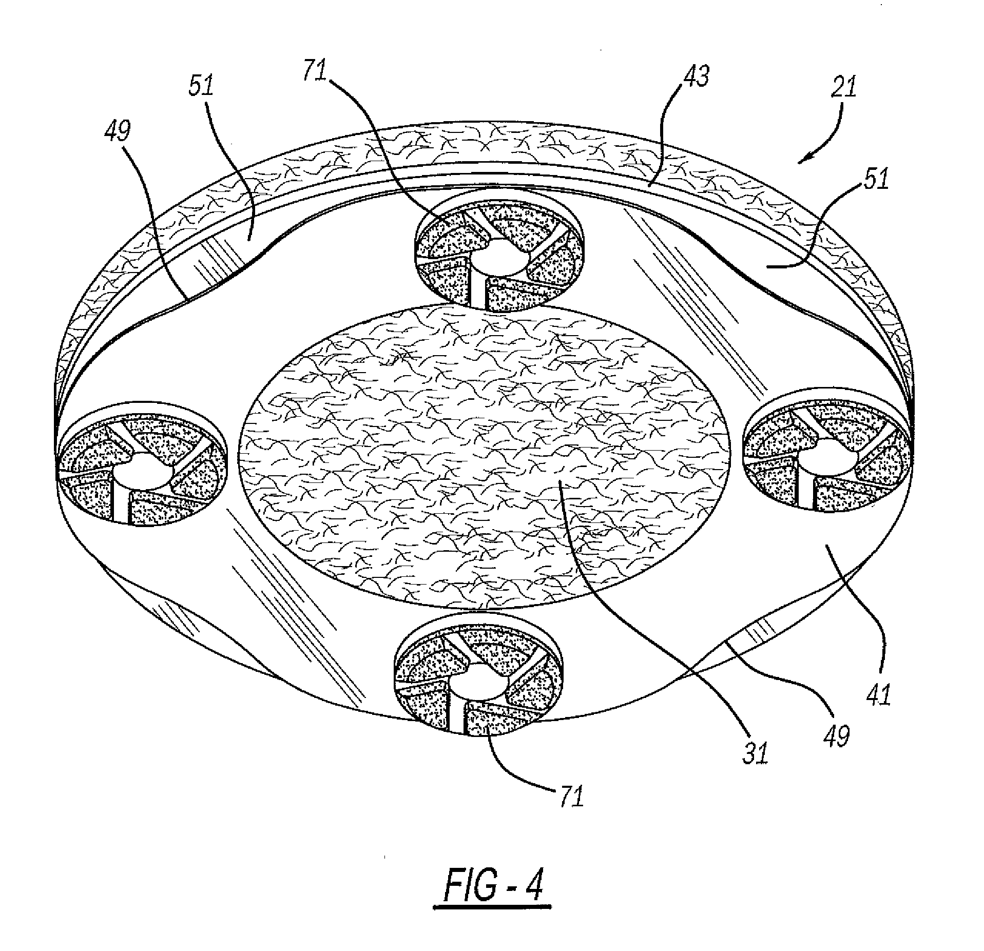
[0008] FIG. 4 is a bottom perspective view showing the first embodiment pad assembly;
[0009] FIG. 5 is a bottom, exploded perspective view showing the first embodiment pad assembly;
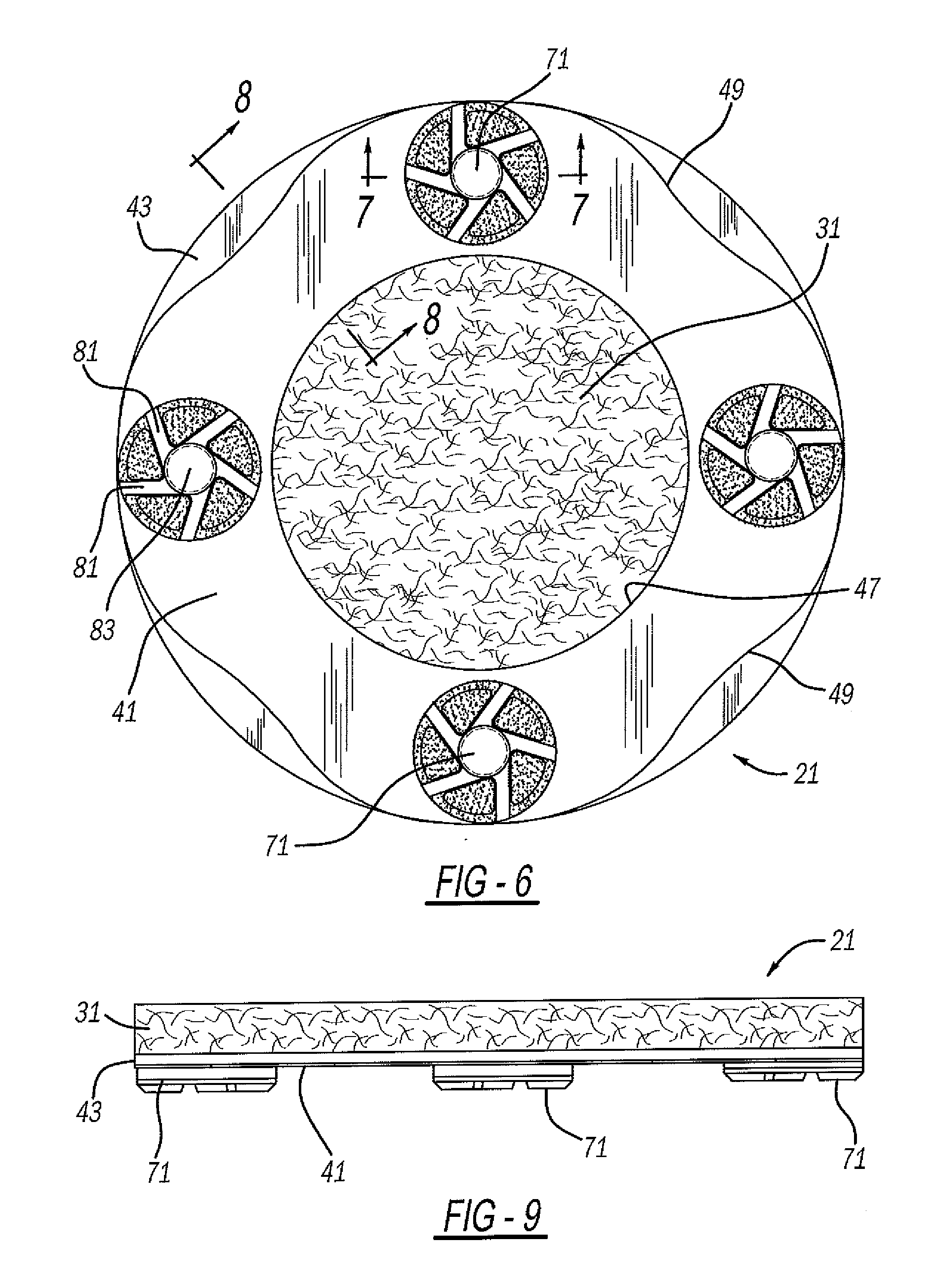
[0010] FIG. 6 is a bottom elevational view showing the first embodiment pad assembly;
[0011] FIG. 7 is a cross-sectional view, taken along line 7-7 of FIG. 6, showing the first embodiment pad assembly;
[0012] FIG. 8 is a cross-sectional view, taken along line 8-8 of FIG. 6, showing the first embodiment pad assembly;
[0013] FIG. 9 is a side elevational view showing the first embodiment pad assembly;
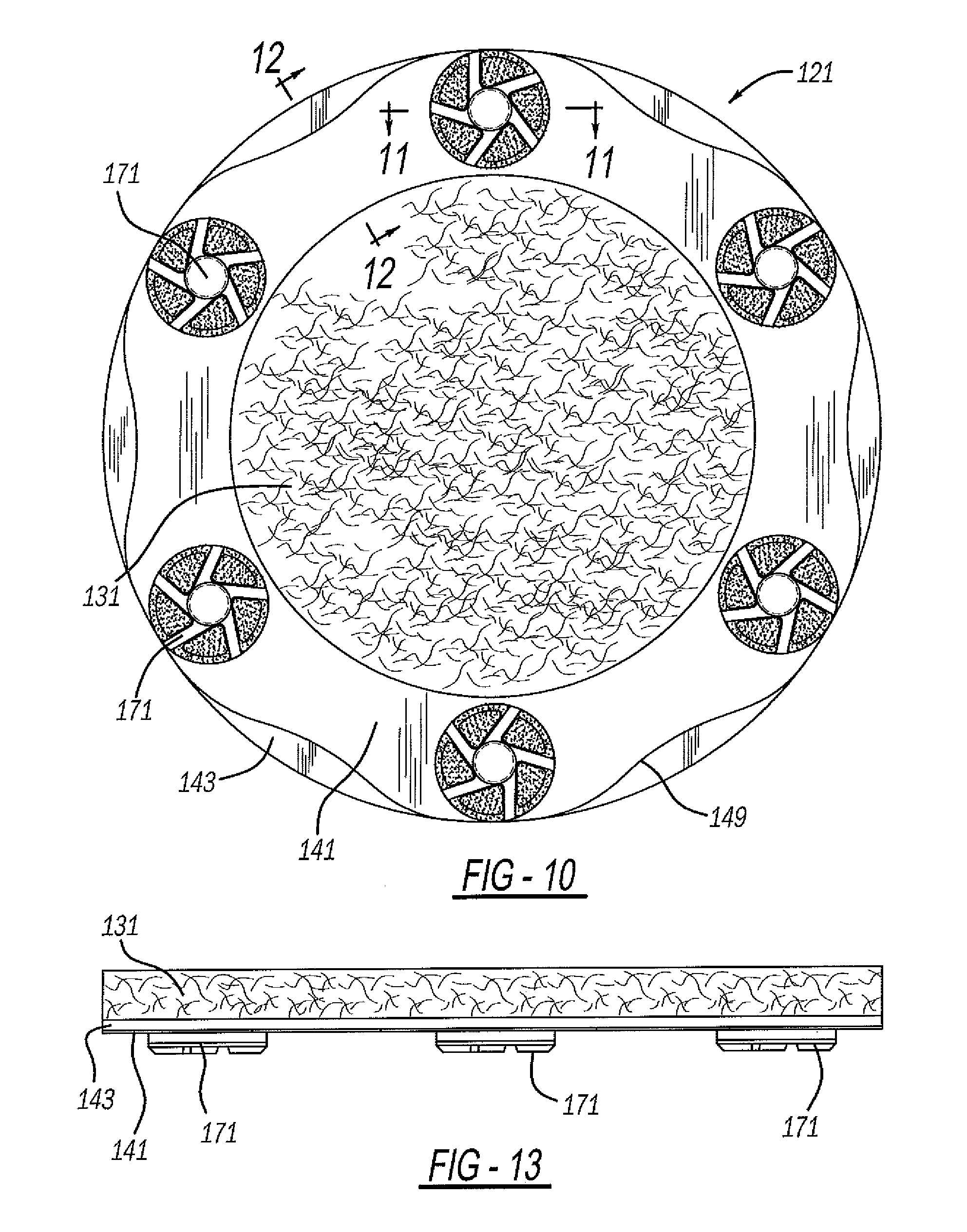
[0014] FIG. 10 is a bottom elevational view showing a second embodiment of the pad assembly;
[0015] FIG. 11 is a cross-sectional view, taken along line 11-11 of FIG. 10, showing the second embodiment pad assembly;
[0016] FIG. 12 is a cross-sectional view, taken along line 12-12 of FIG. 10, showing the second embodiment pad assembly;
[0017] FIG. 13 is a side elevational view showing the second embodiment pad assembly;
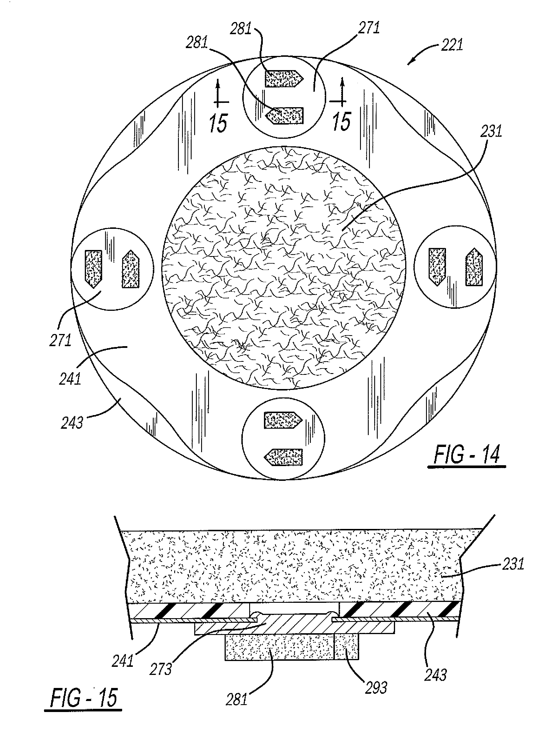
[0018] FIG. 14 is a bottom elevational view showing a third embodiment of the pad assembly;
[0019] FIG. 15 is a cross-sectional view, taken along line 15-15 of FIG. 14, showing the third embodiment pad assembly;
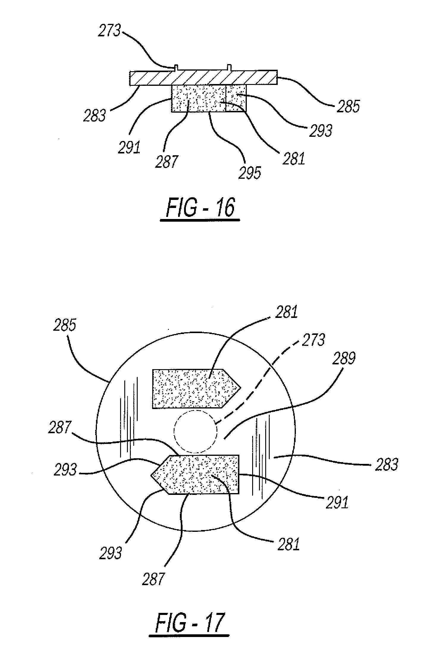
[0020] FIG. 16 is a cross-sectional view, like that of FIG. 15, showing an abrasive tool (before reinforcement ring attachment) of the third embodiment pad;
[0021] FIG. 17 is a bottom elevational view showing the abrasive tool of the third embodiment pad assembly;
[0022] FIG. 18 is a side elevational view showing the third embodiment pad assembly; and
[0023] FIG. 19 is a side elevational view, perpendicular to that of FIG. 18, showing the third embodiment pad assembly.
DETAILED DESCRIPTION
[0024] A first embodiment of a pad assembly 21 is shown in FIGS. 1-4. Pad assembly 21 is used for grinding or polishing composite workpiece surfaces, such as a concrete floor. Pad assemblies 21 are attached to rotating plates 23 which are rotated in a planetary motion by motor-driven arms 25. The plates and arms are part of a ride-on power trowel machine 27 or walk-behind machine. Such machines are disclosed in U.S. Pat. No. 7,815,393, entitled "Mounting Adapter for Concrete Surface Processing Tool" which issued to Snyder et al. on Oct. 19, 2010, U.S. Pat. No. 6,536,989 entitled "Finishing Device for Floors Made of Hardenable Material and Blade Used Therewith" which issued to Rijkers on Mar. 25, 2003, and U.S. Patent Publication No. 2011/0222966 entitled "Hydraulic Riding Trowels with Automatic Load Sensing" which published to Allen et al. on Sep. 15, 2011, all of which are incorporated by reference herein.
[0025] Referring to FIGS. 3-9, pad assembly 21 includes a base pad 31, which is a porous, fibrous, flexible and deformable material, including natural and/or artificial fibers, optionally with resin and diamond particles. Alternately, pad 31 may be rubber, an elastomeric polymer, foam, felt or other durable but flexible material. Base pad 31 is generally circular with generally flat top and bottom surfaces. It has a peripheral diameter of at least 7 inches (178 mm), more preferably 11 inches (279 mm), and a thickness of at least 0.5 inch (13 mm) and more preferably 0.75 inch (20 mm) for this embodiment. Of course, the pad could be made in other sizes. Pad 31 is removeably attached to plate 23 by hook and loop fasteners 33 on a top surface thereof.
[0026] A multilayer reinforcement ring or layer includes a floor-facing and lower ring or layer 41, and a pad-facing or intermediate ring or layer 43. Pad-facing ring 43 is secured to a bottom face of base pad 31, such as by adhesive. The pad-facing reinforcement ring 43 is generally annular having a central opening 45 with a diameter, for example, of approximately 6.3 inches (160 mm), which surrounds a centerline or rotational axis of pad 31. Furthermore, pad-facing ring 43 is preferably cut from a sheet of ABS polymer with an exemplary thickness of about 0.197 inch (5 mm).
[0027] Floor-facing reinforcement ring 41 has an internal hole 47 surrounding the rotational axis of the pad and exposing a center of pad to the floor workpiece. Floor-facing ring 41 has equally spaced apart recesses or arcuate scallops 49 in a peripheral edge thereof. This exposes bottom surface portions 51 of pad-facing ring 43 such that it is unlikely that floor-facing ring 41 will directly contact against the floor even when the floor-facing ring is flexed and tilted. Floor-facing ring 41 is preferably metallic spring steel, having a thickness greater than zero and up to 0.125 inch (preferably 0.25-0.5 mm). Metallic ring 41 is thinner and more flexible than the more rigid yet still flexible polymeric ring 43. Pad-facing reinforcement ring 43 reinforces and adds some stiffness to the floor-facing ring 41, especially where it spans between the abrasive tools, however, the multilayer ring allows some flexibility to pad assembly 21 so it can flex with and follow any floor imperfections thereby producing uniform floor contact for polishing or grinding. Adhesive bonds together at least a majority of the rings at their interfacing surfaces. From a manufacturing and materials cost standpoint, it is less expensive to employ the composite polymer-metal multilayer reinforcement than it is to use only a single thicker metallic ring.
[0028] A plurality of abrasive tools, preferably floor-contacting disks 71, are secured to the bottom surface of floor-facing reinforcement ring 41. In the example shown, abrasive tools 71 are approximately 2 inch (54 mm) disks of diamond particles in a polymeric resin matrix. In the example shown, more than two and, more preferably four, of the abrasive tools are generally equally spaced apart and secured to the multilayer reinforcement ring. The disks are fastened to floor-facing ring 41 by crimping central posts 73 extending from a backside of heads of the disks, into holes 75 in the ring. A slightly larger diameter hole 77 of pad-facing ring 43 is coaxially aligned with each hole 75 to provide clearance for the mushroomed post.
[0029] As one example, the abrasive pattern of the bottom head of each disk 71 employs at least three, and more preferably five, of linearly elongated channels or spokes 81 which outwardly radiate from a solid center 83 with an innermost end of each spoke being offset from a centerline. Alternately, concentric circles or other channel configurations can be used.
[0030] It is noteworthy that inner edges defining holes 45 and 47 of the multilayer ring have a diameter or linear dimension which is larger than a linear dimension of a solid section of the ring layers 41 and 43 which are adjacent to one side of the holes. More preferably, the hole dimensions are at least twice as large as the ring dimensions. The hole relationship is expected to improve floor contact by the fibrous central portion of pad 31 within the inner holes.
[0031] FIGS. 10-13 illustrate another embodiment of a workpiece polishing or grinding pad assembly 121. The flexible and rotatable pad 131 and polymer/metallic multilayer reinforcement ring is essentially the same as the prior embodiment. This configuration, however, includes six abrasive tools or disks 171. Furthermore, rings 141 and 143 have a larger circular peripheral dimension (such as diameter), preferably of 14 inches (355.6 mm). Thus, there are six scalloped recesses 149 in the periphery of the floor-facing reinforcement ring.
[0032] Another embodiment of a workpiece polishing or grinding pad assembly 221 is shown in FIGS. 14-19. A pad 231, polymeric reinforcement ring 243 and metallic reinforcement ring 241 are essentially the same as either of the prior constructions discussed hereinabove. With the present exemplary pad assembly 221, however, each abrasive tool 271 includes multiple raised wedge segments or formations 281 projecting from a bottom surface 283 of a laterally enlarged head 285. Wedges 281 include generally vertical side walls 287 which are parallel, with the inner side walls of each pair of wedges facing each other but being separated by a gap 289. Gap 289 is wider than a width of each wedge 281. Each wedge further includes a rear wall 291, substantially perpendicular to side walls 287, and one or more tapered leading walls 293. Leading walls 293 preferably include two tapers intersecting at an apex point aligned with an elongated centerline of wedge 281. The tapered leading walls are on an end opposite each other for the pair of wedges of this version, which advantageously allows for easy bidirectional assembly to the multilayer reinforcement and allows these tools to be used without a need to reverse their orientation regardless of the rotational direction of the pad.
[0033] In one example, a floor-contacting face 295 is at least 0.25 inch (6.35 mm) and more preferably 0.39 inch (10 mm) below surface 283 of tool head 285. Furthermore, an elongated linear dimension of side walls 287 is greater than a width dimension between sidewalls 287 of each wedge. A post 273 centrally projects from the backside of head 285 for crimped attachment to the multilayer reinforcement. A periphery of head 285 is somewhat circular and disk-like although other somewhat polygonal or arcuate shapes may be employed, although some of the advantages may not be realized. Moreover, at least three, and more preferably four tools 271 are provided for an 11 inch (279 mm) outside diameter pad while six tools 271 are provided for a 14 inch (355.6 mm) outside diameter pad. These wedge tool configurations may be employed with a single reinforcement, multilayer reinforcement, inner or outer edge recessed reinforcement or even directly adhered to the pad, although many of the aforementioned multilayer reinforcement ring benefits may not be achieved.
[0034] The wedge tools are ideally suited for removing an epoxy coating, paint or other materials from a workpiece, especially a cement floor, through rotation by a powered machine. While angled or tapered leading walls 293 are functionally advantageous, the overall shapes and spacing of wedges 281 on the tools or disks 271 have ornamental and aesthetic benefits. Furthermore, the exact scalloped shapes of the recesses for floor-facing reinforcement ring 241 also has ornamental features.
[0035] While various embodiments have been disclosed, it should be appreciated that additional variations of the pad assembly are also envisioned. For example, while preferred dimensions have been disclosed hereinabove, it should alternately be appreciated that other dimensions may be employed; for example a peripheral pad diameter of at least 10 inches (254 mm) may be employed and disk diameters of 0.5-2.5 inches (12.7-63.5 mm) may also be employed. Moreover, circular peripheral shapes for the pad, reinforcement ring and disks are preferred, however, other arcuate or even generally polygonal peripheral shapes may be used although certain of the present advantages may not be fully realized. Alternate recess shapes are possible. It is also envisioned that different abrading patterns may be employed on the abrasive tools (such as disks) which may be attached to the multilayer reinforcement ring with a rivet, adhesive or other fasteners.
[0036] Furthermore, it is also possible to employ three or more reinforcement layers with differing characteristics, although some of the present cost advantages may not be achieved. Alternately, other fastening of the rings can be used but adhesive is more beneficial. While certain materials have been disclosed it should be appreciated that alternate materials may be used although all of the present advantages may not be fully achieved. It is also noteworthy that any of the preceding features may be interchanged and intermixed with any of the others. Accordingly, any and/or all of the dependent claims may depend from all of their preceding claims and may be combined together in any combination. Variations are not to be regarded as a departure from the present disclosure, and all such modifications are entitled to be included within the scope and sprit of the present invention.
* * * * *
D00000
D00001
D00002
D00003
D00004
D00005
D00006
D00007
D00008
D00009
D00010
D00011
XML
uspto.report is an independent third-party trademark research tool that is not affiliated, endorsed, or sponsored by the United States Patent and Trademark Office (USPTO) or any other governmental organization. The information provided by uspto.report is based on publicly available data at the time of writing and is intended for informational purposes only.
While we strive to provide accurate and up-to-date information, we do not guarantee the accuracy, completeness, reliability, or suitability of the information displayed on this site. The use of this site is at your own risk. Any reliance you place on such information is therefore strictly at your own risk.
All official trademark data, including owner information, should be verified by visiting the official USPTO website at www.uspto.gov. This site is not intended to replace professional legal advice and should not be used as a substitute for consulting with a legal professional who is knowledgeable about trademark law.