Method For Joining Members
MAEDA; Yasuhiro ; et al.
U.S. patent application number 16/352732 was filed with the patent office on 2019-07-11 for method for joining members. This patent application is currently assigned to KABUSHIKI KAISHA KOBE SEIKO SHO (KOBE STEEL, LTD.). The applicant listed for this patent is KABUSHIKI KAISHA KOBE SEIKO SHO (KOBE STEEL, LTD.). Invention is credited to Jiro IWAYA, Hideto KATSUMA, Yasuhiro MAEDA, Junya NAITOU.
| Application Number | 20190210088 16/352732 |
| Document ID | / |
| Family ID | 56691031 |
| Filed Date | 2019-07-11 |
View All Diagrams
| United States Patent Application | 20190210088 |
| Kind Code | A1 |
| MAEDA; Yasuhiro ; et al. | July 11, 2019 |
METHOD FOR JOINING MEMBERS
Abstract
In the present invention, a method for joining members involves preparing a steel component having a bottom wall in which a hole is provided, and a hollow aluminum pipe. The aluminum pipe is slipped through the hole in the steel component and passed through the bottom wall, rubber is inserted into the interior of the aluminum pipe, and the rubber is compressed in the direction of the axis (L) of the aluminum pipe and induced to distend towards the outside from the inside. As a result of the foregoing, at least a section of the aluminum pipe slipped through the hole is induced to undergo expansion and is joined by clinching to the bottom wall. This method for joining members reduces the load on the members, improves the joint strength, and enables two members to be joined at reduced cost.
| Inventors: | MAEDA; Yasuhiro; (Kobe-shi, JP) ; IWAYA; Jiro; (Nagoya-shi, JP) ; NAITOU; Junya; (Kobe-shi, JP) ; KATSUMA; Hideto; (Kobe-shi, JP) | ||||||||||
| Applicant: |
|
||||||||||
|---|---|---|---|---|---|---|---|---|---|---|---|
| Assignee: | KABUSHIKI KAISHA KOBE SEIKO SHO
(KOBE STEEL, LTD.) Hyogo JP |
||||||||||
| Family ID: | 56691031 | ||||||||||
| Appl. No.: | 16/352732 | ||||||||||
| Filed: | March 13, 2019 |
Related U.S. Patent Documents
| Application Number | Filing Date | Patent Number | ||
|---|---|---|---|---|
| 15546021 | Jul 25, 2017 | |||
| PCT/JP2016/050046 | Jan 4, 2016 | |||
| 16352732 | ||||
| Current U.S. Class: | 1/1 |
| Current CPC Class: | B21D 39/206 20130101; B21D 39/20 20130101; B21D 39/06 20130101; B21D 39/032 20130101 |
| International Class: | B21D 39/06 20060101 B21D039/06; B21D 39/20 20060101 B21D039/20; B21D 39/03 20060101 B21D039/03 |
Foreign Application Data
| Date | Code | Application Number |
|---|---|---|
| Feb 6, 2015 | JP | 2015-022573 |
| Jun 19, 2015 | JP | 2015-124075 |
Claims
1. A method for joining members, comprising: preparing a first member and a hollow second member, the first member having a first section provided with a first hole; fitting the second member into the first hole in the first member so as to cause the second member to extend through the first section; inserting an elastic body into the second member; compressing the elastic body in a direction of an axis of the second member so as to cause the elastic body to expand from an inner side toward an outer side, and thus causing at least a part of the second member fitted in the first hole to expand so as to become clinched to the first section; and wherein the first member has a convex bead part, which arounds the first hole and extends in axial direction of the surface of the first member; and the convex bead part is fitted to second member to be expanded together with second member.
2. The method for joining members according to claim 1, wherein a shape of the first hole in the first member is analogous to a cross-sectional shape of the part of the second member fitted in the first hole.
3. The method for joining members according to claim 1, wherein an outer-frame mold is disposed at the outer side of the second member, and at least a part of the second member is formed to extend along the outer-frame mold so as to become clinched.
4. The method for joining members according to claim 1, wherein an outer-frame mold is disposed at the outer side of the second member, and clinching is performed while partially limiting expansion of the second member by using the outer-frame mold.
5. The method for joining members according to claim 1, wherein the second member is also compressed in the direction of the axis when the elastic body is compressed.
6. The method for joining members according to claim 1, wherein an edge of the first hole is burred.
7. The method for joining members according to claim 1, wherein a surface different from a surface provided with the first hole has a bead section protruding in the direction of the axis, and clinching is performed by including the bead section.
8. The method for joining members according to claim 1, wherein the first member includes a second section having a second hole and is clinched to the second member at the first hole and the second hole.
9. The method for joining members according to claim 1, wherein the elastic body is split at a joining section between the first member and the second member.
10. The method for joining members according to claim 1, wherein a plate is inserted between split pieces of the elastic body.
11. The method for joining members according to claim 1, wherein the second member includes an outer wall provided with a partition wall therein and extending in the direction of the axis, and wherein clinching is performed by inserting a plurality of the elastic bodies in spaces partitioned by the partition wall.
12. The method for joining members according to claim 1, wherein the second member includes an end surface inclined relative to the axis, and wherein opposite end surfaces of the elastic body in the direction of the axis are parallel to the inclined surface.
13. The method for joining members according to claim 1, wherein the first member includes an upright wall parallel to the axis, and wherein clinching is performed while restraining deformation of the upright wall by using a fixation jig.
Description
CROSS-REFERENCE TO RELATED APPLICATIONS
[0001] This application is a Divisional of U.S. patent application Ser. No. 15/546,021 filed Jul. 25, 2017, which is the U.S. National Phase of International Application No. PCT/JP2016/050046 filed Jan. 4, 2016, which claims priority from Japanese Patent Application Nos. 2015-124075 filed Jun. 19, 2015 and 2015-022573 filed Feb. 6, 2015.
TECHNICAL FIELD
[0002] The present invention relates to methods for joining members.
BACKGROUND ART
[0003] In order to achieve weight reduction and improved safety in automobiles, high-strength steel sheets composed of so-called high-tensile steel are used. Although effective for weight reduction and improved safety, such high-tensile steel is still heavy compared with low specific gravity materials, such as aluminum. Moreover, high-tensile steel is problematic in terms of low formability due to its high strength, increasing forming load, and also low dimensional accuracy. In order to solve these problems, a multi-material process that involves using a steel component together with an extruded product, a molded product, or a press-formed product that use aluminum, which has lower specific gravity than steel sheets, has been performed in recent years.
[0004] A problem with this multi-material process is in the joining of the steel component and the aluminum component. In the welding technology typified by spot-welding, fragile intermetallic compounds (IMC) occur at the interface between the steel sheet and the aluminum sheet. Thus, joining techniques, such as an electromagnetic-forming joining technique, a screw-fastening technique typified by bolts and nuts, a friction-stir-welding (FSW) technique, a riveting technique, a self-piercing-riveting (SPR) technique, a mechanical clinching technique, and a bonding technique, are put to practical use.
[0005] A clinching process based on electromagnetic forming involves inserting a solenoid forming coil into a pipe-shaped component fitted to a counterpart component and causing induced current to occur in the pipe serving as a conductor in accordance with a changing magnetic field occurring as a result of applying impulse current to the coil. An electromagnetic force is generated between the magnetic field caused by primary current in the coil and the induced current flowing oppositely in the circumferential direction of the pipe, and the pipe receives an outward force and thus expands, thereby becoming clinched to the counterpart component. This joining method is suitable for copper and aluminum, which have high electric conductivity, and is put to practical use in some techniques for joining together automobile components.
[0006] Patent Literature 1 discloses a clinching technique based on electromagnetic forming for performing a multi-material process. In Patent Literature 1, a bumper reinforcement member formed of a metallic material that is hollow in cross section is caused to expand by electromagnetic forming and is engaged with holes provided in a bumper stay composed of an aluminum alloy so as to be joined thereto.
CITATION LIST
Patent Literature
[0007] PTL 1: Japanese Unexamined Patent Application Publication No. 2007-284039
SUMMARY OF INVENTION
Technical Problem
[0008] As in Patent Literature 1, electromagnetic forming is suitable for clinching a hollow component composed of copper or aluminum having high electric conductivity to a counterpart component, and a circular shape is preferred due to this joining mechanism.
[0009] However, the joining technique based on electromagnetic forming requires that the inner diameter of the solenoid coil to be used be smaller than that of the aluminum component (i.e., aluminum pipe). When the diameter of a coil is to be reduced when joining together small-diameter components, there are problems in terms of difficulties in manufacturing of the coil, as well as performance and durability thereof. With regard to difficulties in manufacturing, it is difficult to form a conductor into the shape of a coil, leading to stricter limitations with respect to the material and the cross-sectional shape of the conductor. In addition, the conductor cross-sectionally deforms when being formed into the shape of a coil. Moreover, a new capital investment becomes necessary, such as requiring a large-capacity high-voltage capacitor. Furthermore, the joining is not possible if the aluminum component has an angular cross-sectional shape, a hole, or a slit.
[0010] An object of the present invention is to provide a method for joining members, by which two members can be joined together at low cost while reducing the load on the members and increasing the joint strength.
Solution to Problem
[0011] The present invention provides a joining method including: preparing a first member and a hollow second member, the first member having a first section provided with a first hole; fitting the second member into the first hole in the first member so as to cause the second member to extend through the first section; inserting an elastic body into the second member; and compressing the elastic body in a direction of an axis of the second member so as to cause the elastic body to expand from an inner side toward an outer side, and thus causing at least a part of the second member fitted in the first hole to expand so as to become clinched to the first section.
[0012] According to this method, the elastic body is caused to expand outward so that the second member expands uniformly, thereby preventing local deformation and reducing the load on the members. This is because the second member can be uniformly deformed by utilizing the properties in which the elastic body compressed in the direction of the axis expands uniformly from the inner side toward the outer side. Therefore, fit accuracy can be improved, thereby achieving increased joint strength. Moreover, this is an easier method, as compared with an electromagnetic forming method or other machining methods. An electromagnetic forming method is usable only on electrically conductive materials and has limitations with respect to cross-sectional shapes and dimensions depending on coils to be used. In contrast, this method is not dependent on materials and has no limitations related to cross-sectional shapes and dimensions. Moreover, since the method is executable in a facility that applies a compressive force to the elastic body, an electrical facility that requires a large-capacity capacitor is not necessary. Consequently, the two members can be joined together at low cost.
[0013] Furthermore, a shape of the first hole in the first member may be analogous to a cross-sectional shape of the part of the second member fitted in the first hole.
[0014] According to this method, the first member and the second member have shapes analogous to each other so that the joining process can be performed by causing the second member to expand uniformly, thereby preventing local load from occurring in the first member and the second member.
[0015] Furthermore, an outer-frame mold may be disposed at the outer side of the second member, and at least a part of the second member may be formed to extend along the outer-frame mold so as to become clinched.
[0016] According to this method, the second member can be deformed to a freely-chosen shape by using outer-frame molds with various inner-surface shapes. The deformation shape can be appropriately selected in view of, for example, component performance and can be set in accordance with the intended purpose.
[0017] Furthermore, an outer-frame mold may be disposed at the outer side of the second member, and clinching may be performed while partially limiting expansion of the second member by using the outer-frame mold.
[0018] According to this method, by disposing the outer-frame mold, an expanding region of the second member is regulated, so that the expanding region can be controlled with high accuracy. This expanding region refers to a region in which the second member expands outward.
[0019] Furthermore, the second member may also be compressed in the direction of the axis when the elastic body is compressed.
[0020] According to this method, the second member is also compressed in the direction of the axis so as to assist with outward expansion of the second member. Specifically, together with the expanding force applied by the elastic body from the inner side of the second member, the second member can be expanded more reliably, thereby enabling clinching.
[0021] Furthermore, an edge of the first hole may be burred.
[0022] According to this method, the edge of the hole in the first member is burred so that the strength of the hole and the first section of the first member can be increased. Consequently, the first member can be prevented from deforming, the second member can be prevented from being damaged, and the joint strength between the two members can be increased.
[0023] Furthermore, a surface different from a surface provided with the first hole may have a bead section protruding in the direction of the axis, and clinching may be performed by including the bead section.
[0024] According to this method, because clinching is performed by including the bead section, the two members can be fixed to each other more securely, and the joint strength therebetween can be further increased. In particular, in a case where the second member has a circular cross-sectional shape, the second member can be prevented from rotating relative to the first member.
[0025] Furthermore, the first member may include a second section having a second hole and may be clinched to the second member at the first hole and the second hole.
[0026] According to this method, clinching is performed at two locations so that the joint strength can be further increased, as compared with the case where clinching is performed at a single location.
[0027] Furthermore, the elastic body may be split at a joining section between the first member and the second member.
[0028] According to this method, the elastic body is split at the joining section so that deformation of the joining section of the first member can be prevented. Specifically, the elastic body is split such that the elastic body is not disposed near the joining section, whereby the second member does not receive an expanding force from the elastic body near the joining section and thus does not expand near the joining section. Consequently, the first member does not receive a force from the second member near the joining section, so that the shape of the joining section can be maintained.
[0029] Furthermore, a plate may be inserted between split pieces of the elastic body.
[0030] According to this method, the plate exists in the joining section so that deformation of the joining section of the first member can be prevented more reliably. Because the plate does not expand even by receiving a compressive force in the direction of the axis, an expanding force is not applied to the joining section, so that the joining section can maintain its original shape more reliably.
[0031] Furthermore, the second member may include an outer wall provided with a partition wall therein and extending in the direction of the axis, and clinching may be performed by inserting a plurality of the elastic bodies in spaces partitioned by the partition wall.
[0032] According to this method, because the clinching process is performed by using the plurality of elastic bodies, concentration of stress caused by deformation can be prevented, so that the load on the first member and the second member can be reduced.
[0033] Furthermore, the second member may include an end surface inclined relative to the axis, and opposite end surfaces of the elastic body in the direction of the axis may be parallel to the inclined surface.
[0034] Accordingly, this method can be used for clinching the first member and the second member together in an inclined state, which is often seen from a practical standpoint. In particular, opposite end surfaces of the elastic body are given the same angle as the joining angle, so that the elastic body expands uniformly, whereby the second member can be expanded uniformly.
[0035] Furthermore, the first member may include an upright wall parallel to the axis, and clinching may be performed while restraining deformation of the upright wall by using a fixation jig.
[0036] According to this method, deformation of the first member is restrained by the jig, so that deformation of the first member caused by expansion of the second member can be suppressed.
Advantageous Effects of Invention
[0037] According to the present invention, the second member is caused to expand uniformly by causing the elastic body to expand from the inner side toward the outer side, thereby preventing local deformation and reducing the load on the members. Therefore, fit accuracy can be improved, thereby achieving increased joint strength. Moreover, since this is an easier method, as compared with an electromagnetic forming method or other machining methods, the two members can be joined together at low cost.
BRIEF DESCRIPTION OF DRAWINGS
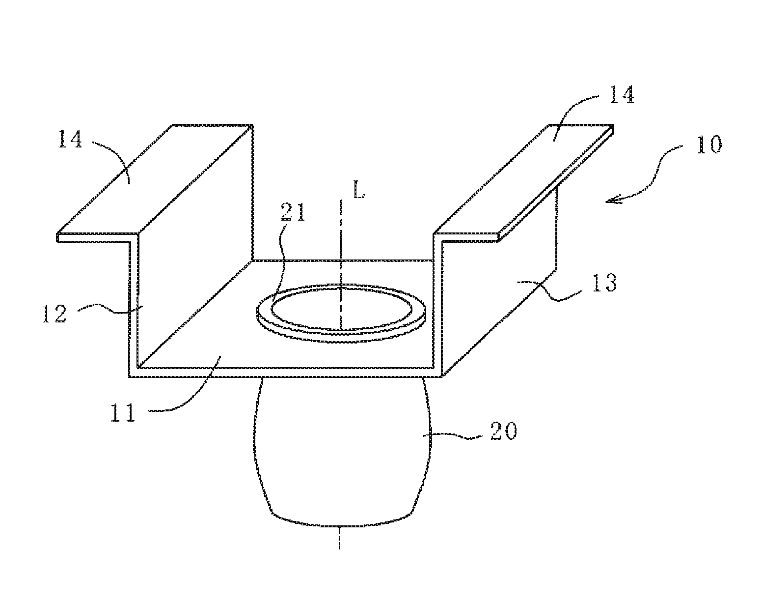
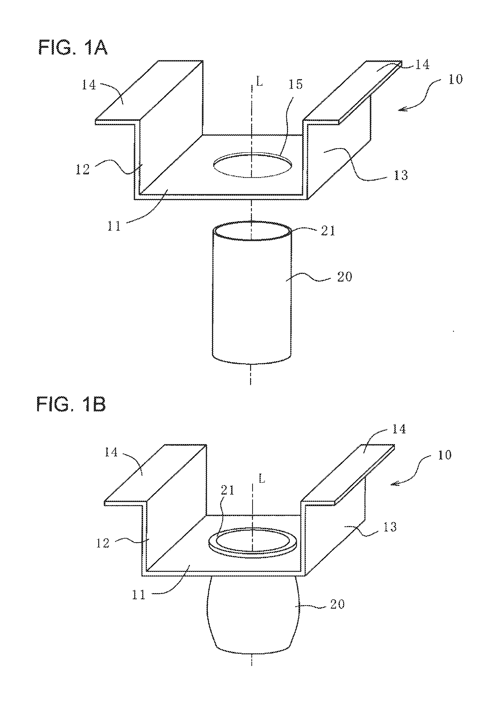
[0038] FIG. 1A is a perspective view of a channel-type steel component having a circular hole and an aluminum pipe having a circular cross-sectional shape.
[0039] FIG. 1B is a perspective view of the steel component and the aluminum pipe in FIG. 1A in a clinched state.
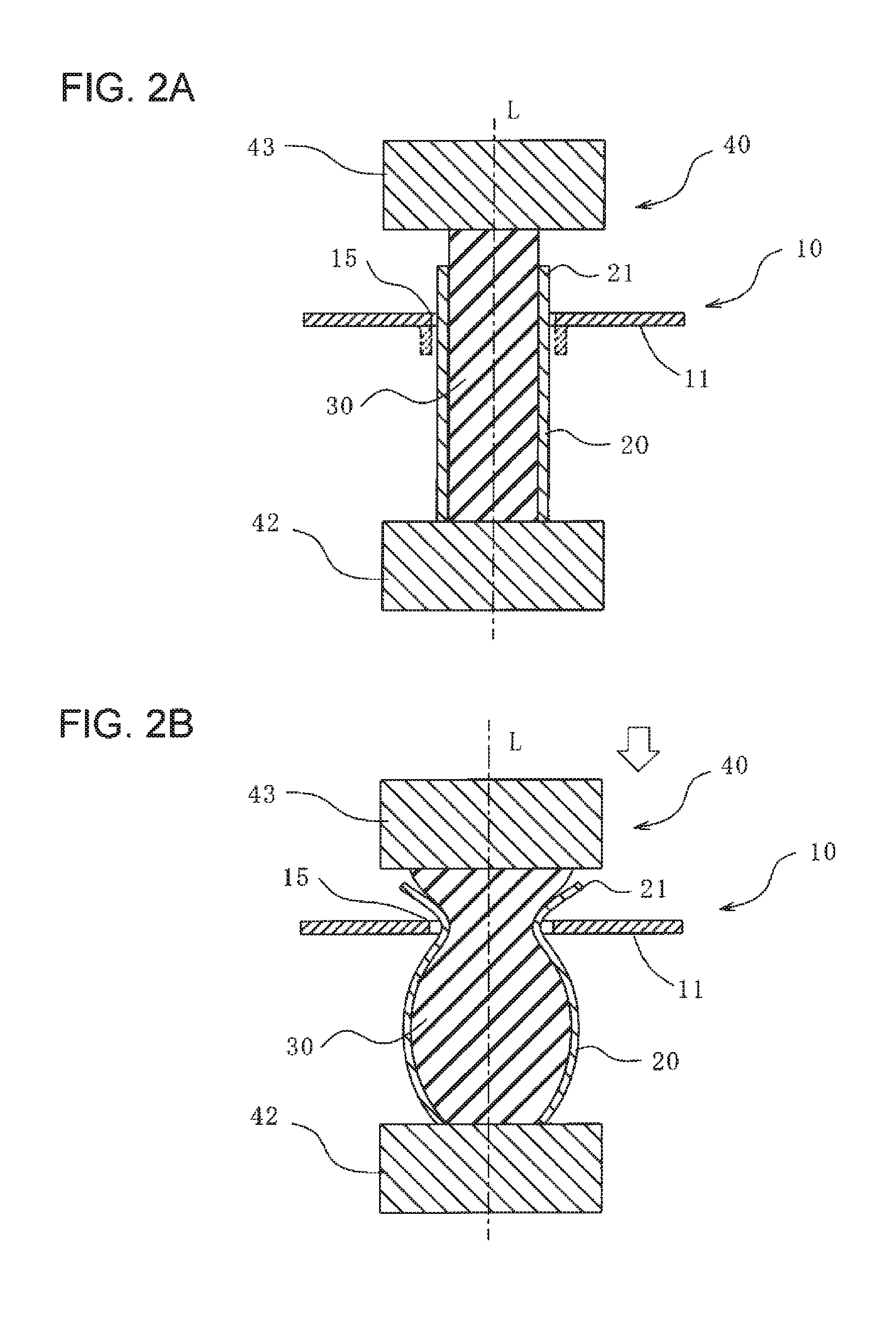
[0040] FIG. 2A is a cross-sectional view illustrating a state before a clinching process according to a first embodiment of the present invention.
[0041] FIG. 2B is a cross-sectional view illustrating a state where the clinching process according to the first embodiment of the present invention is being performed.
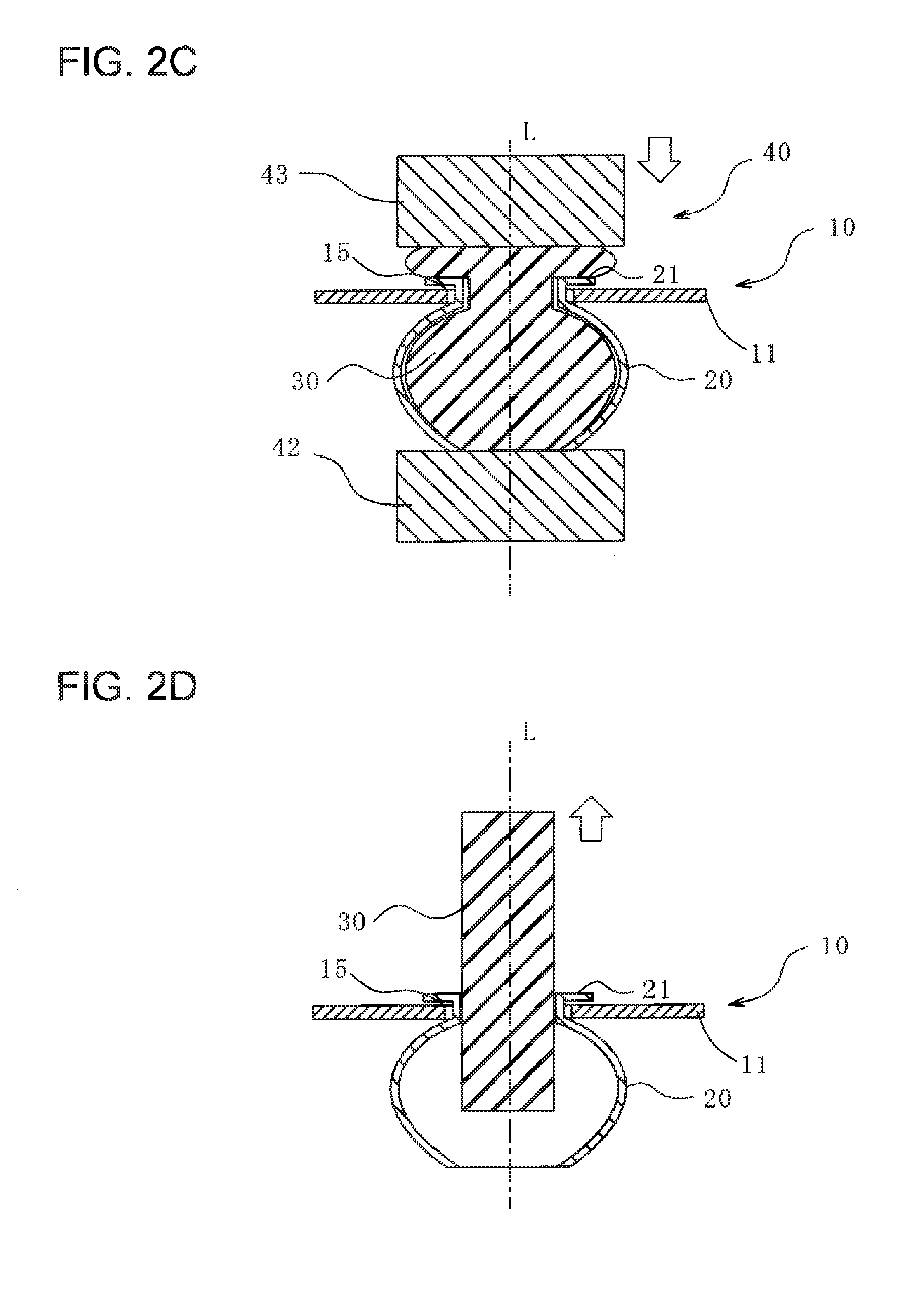
[0042] FIG. 2C is a cross-sectional view illustrating a state after the clinching process according to the first embodiment of the present invention.
[0043] FIG. 2D is a cross-sectional view illustrating a state where a rubber piece is being pulled out after the clinching process according to the first embodiment of the present invention.
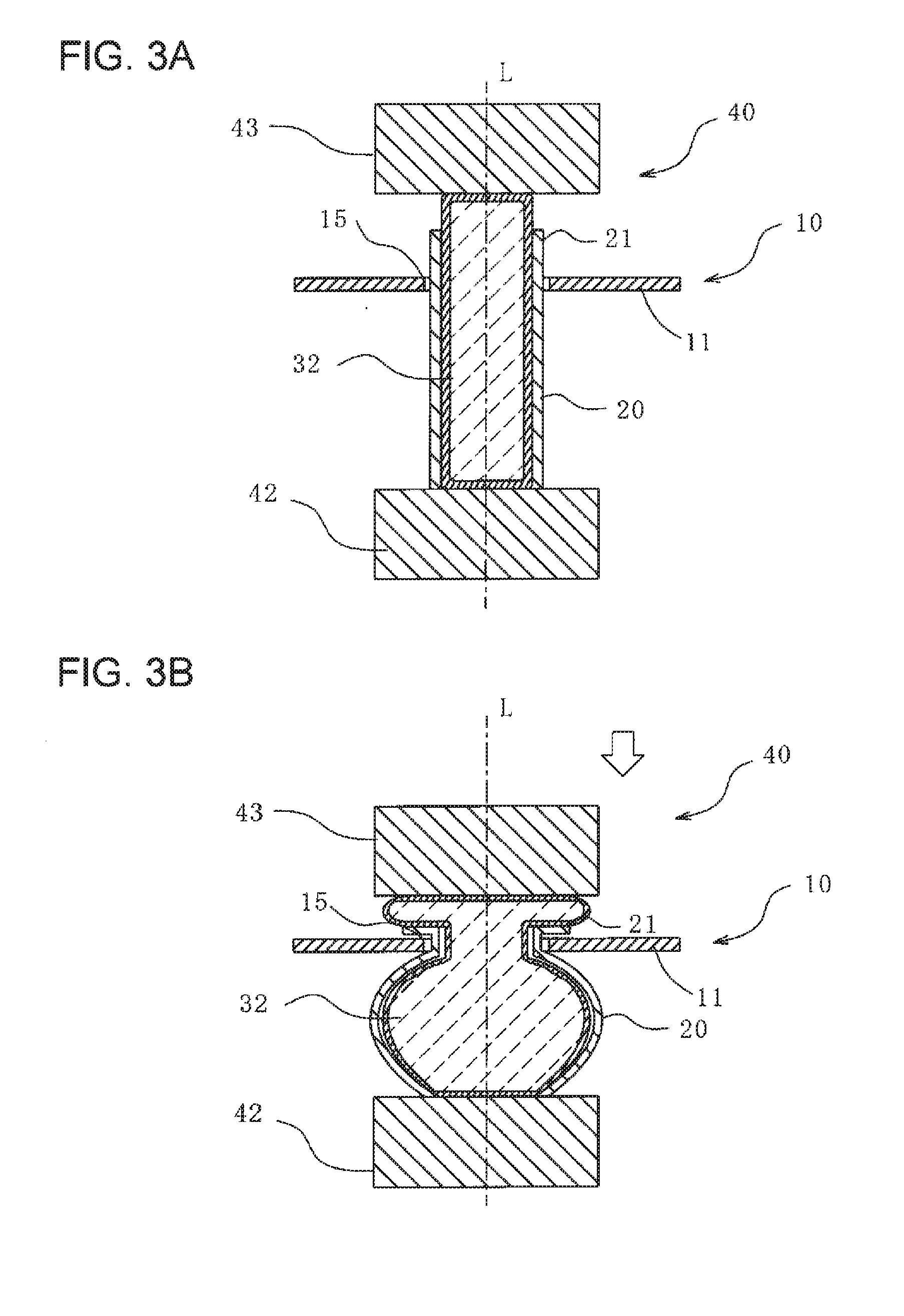
[0044] FIG. 3A is a cross-sectional view illustrating a state before the clinching process when a rubber piece according to a modification of the first embodiment of the present invention is a fluid sealing member.
[0045] FIG. 3B is a cross-sectional view illustrating a state after the clinching process when the rubber piece according to the modification of the first embodiment of the present invention is a fluid sealing member.
[0046] FIG. 4A is a perspective view of a steel component having a circular hole and an aluminum pipe having a rectangular cross-sectional shape.
[0047] FIG. 4B is a perspective view of a steel component having a rectangular hole and an aluminum pipe having a circular cross-sectional shape.
[0048] FIG. 5A is a cross-sectional view of an example of a joining section of a steel component having undergone a burring process.
[0049] FIG. 5B is a cross-sectional view of another example of a joining section of a steel component having undergone a burring process.
[0050] FIG. 5C is a cross-sectional view of another example of a joining section of a steel component having undergone a burring process.
[0051] FIG. 6A is a perspective view of a joining section of a steel component having a circular hole having undergone a burring process.
[0052] FIG. 6B is a perspective view of a joining section of a steel component having a rectangular hole having undergone a burring process.
[0053] FIG. 7A is a cross-sectional view illustrating a state before a clinching process performed by using an outer-frame mold according to a second embodiment of the present invention.
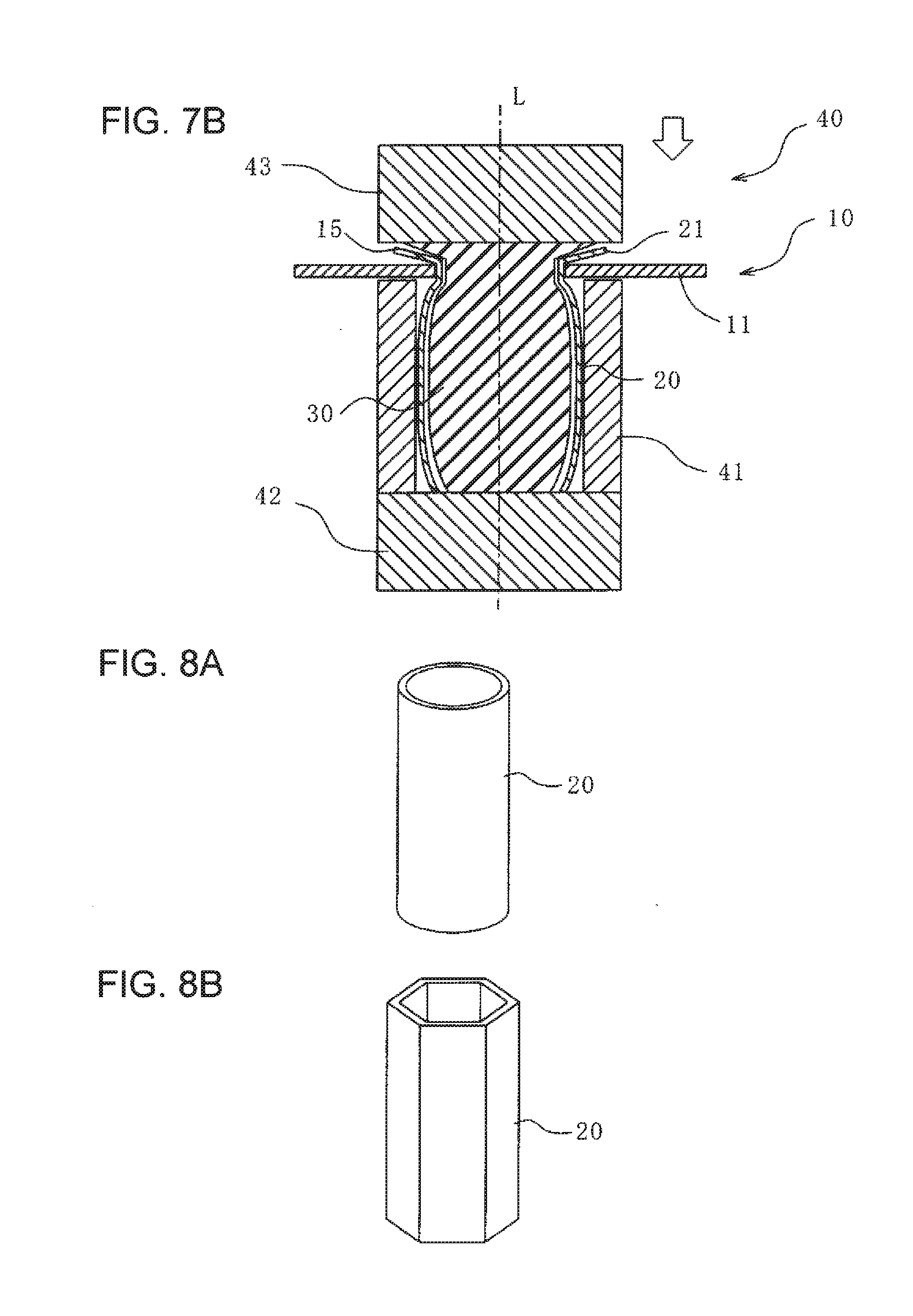
[0054] FIG. 7B is a cross-sectional view illustrating a state after the clinching process performed by using the outer-frame mold according to the second embodiment of the present invention.
[0055] FIG. 8A is a perspective view of an aluminum pipe formed into a cylindrical tube shape.
[0056] FIG. 8B is a perspective view of an aluminum pipe formed into a hexagonal tube shape.
[0057] FIG. 8C is a perspective view of an aluminum pipe formed into a cross tube shape.
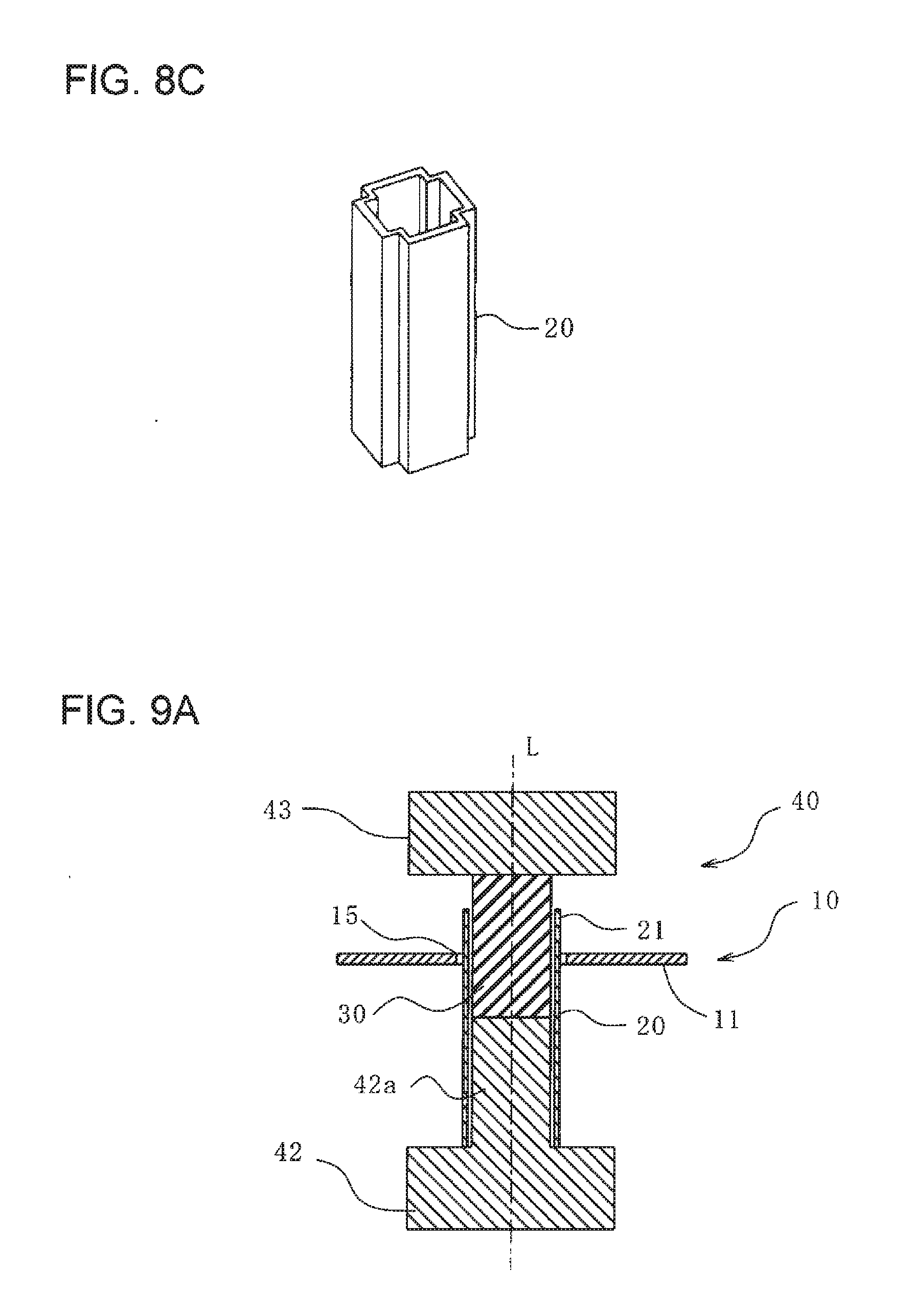
[0058] FIG. 9A is a cross-sectional view illustrating a state before a clinching process performed by disposing a rubber piece only near a joining section in accordance with a third embodiment of the present invention.
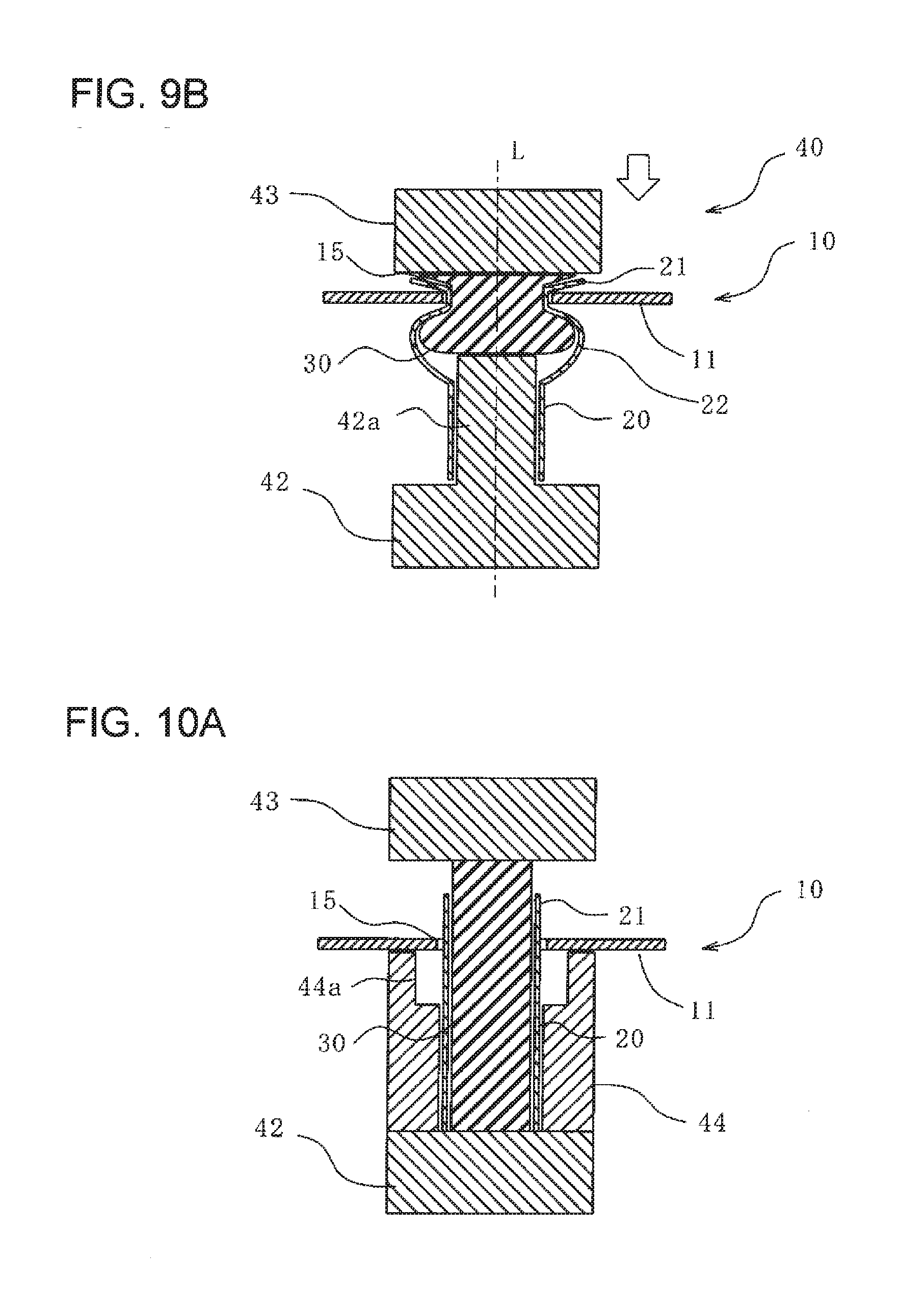
[0059] FIG. 9B is a cross-sectional view illustrating a state after the clinching process performed by disposing the rubber piece only near the joining section in accordance with the third embodiment of the present invention.
[0060] FIG. 10A is a cross-sectional view illustrating a state before a clinching process in which an aluminum pipe is partially expanded by using an outer-frame mold according to a modification of the third embodiment of the present invention.
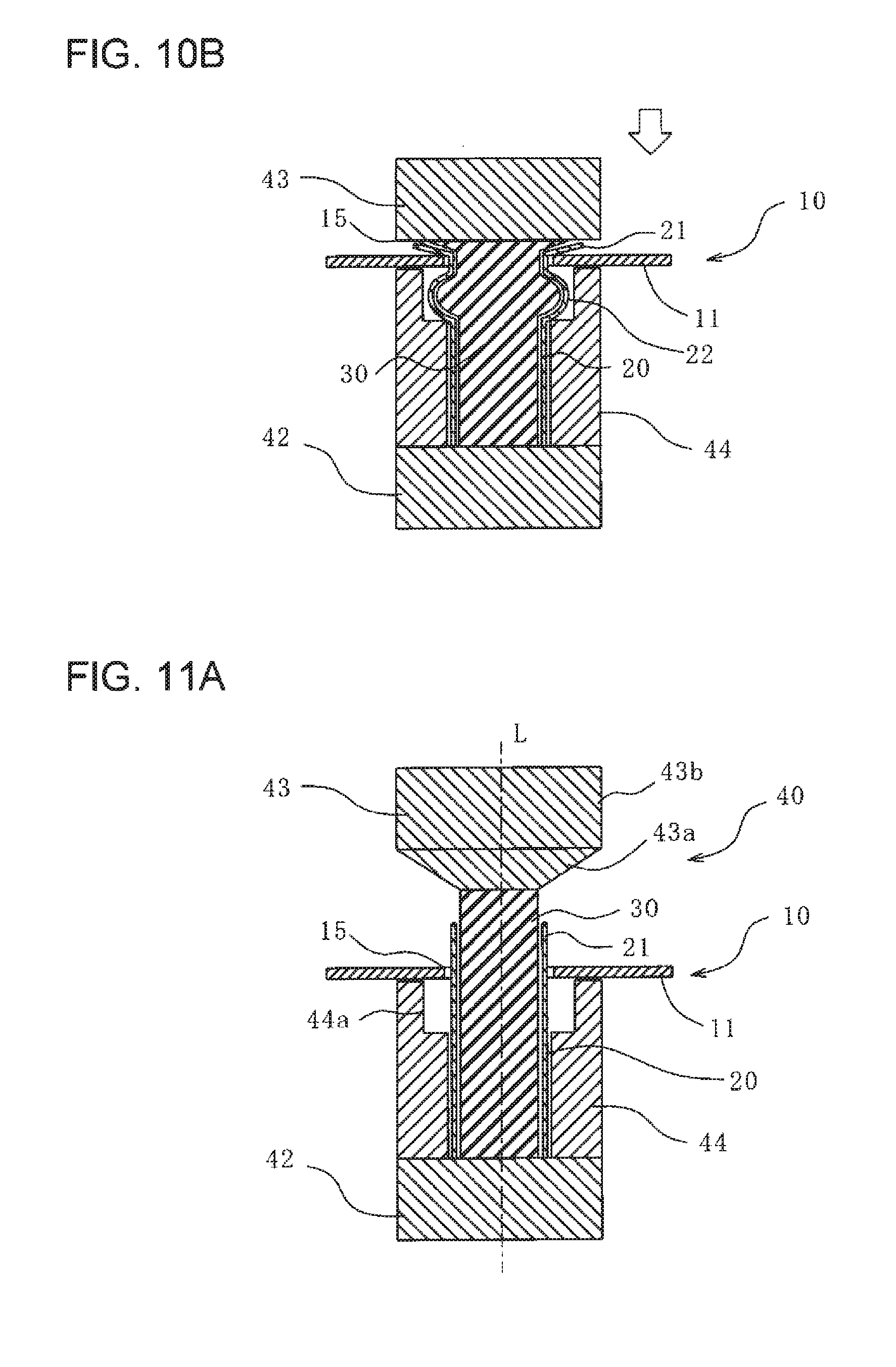
[0061] FIG. 10B is a cross-sectional view illustrating a state after the clinching process in which the aluminum pipe is partially expanded by using the outer-frame mold according to the modification of the third embodiment of the present invention.
[0062] FIG. 11A is a cross-sectional view illustrating a state before a clinching process performed by using a truncated-cone-shaped indenter according to a fourth embodiment of the present invention.
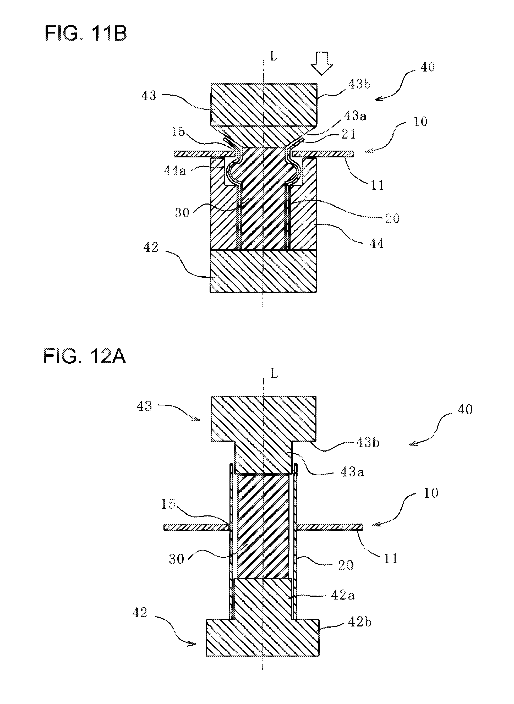
[0063] FIG. 11B is a cross-sectional view illustrating a state after the clinching process performed by using the truncated-cone-shaped indenter according to the fourth embodiment of the present invention.
[0064] FIG. 12A is a cross-sectional view illustrating a state before a clinching process performed by compressing an aluminum pipe according to a fifth embodiment of the present invention in an axial direction.
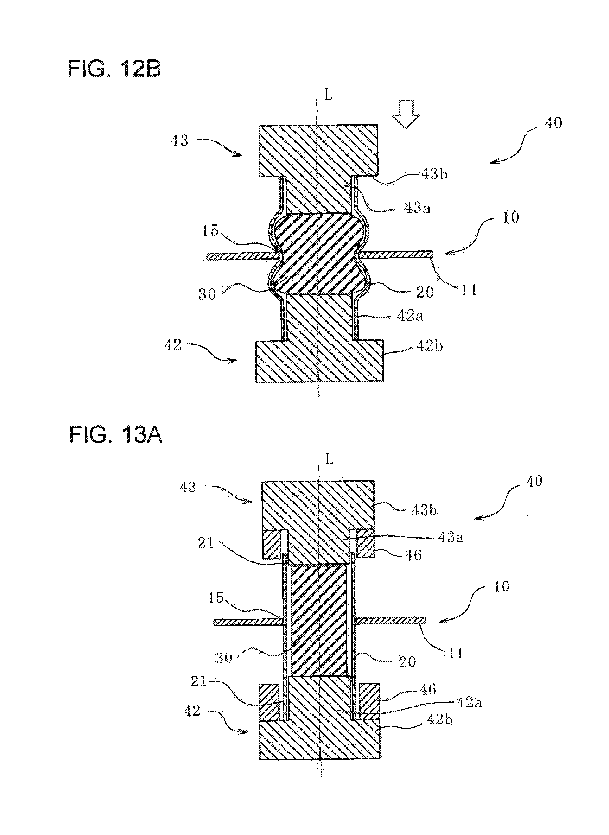
[0065] FIG. 12B is a cross-sectional view illustrating a state after the clinching process performed by compressing the aluminum pipe according to the fifth embodiment of the present invention in the axial direction.
[0066] FIG. 13A is a cross-sectional view illustrating a state before a clinching process performed by using an indenter equipped with an outer frame in accordance with a modification of the fifth embodiment of the present invention.
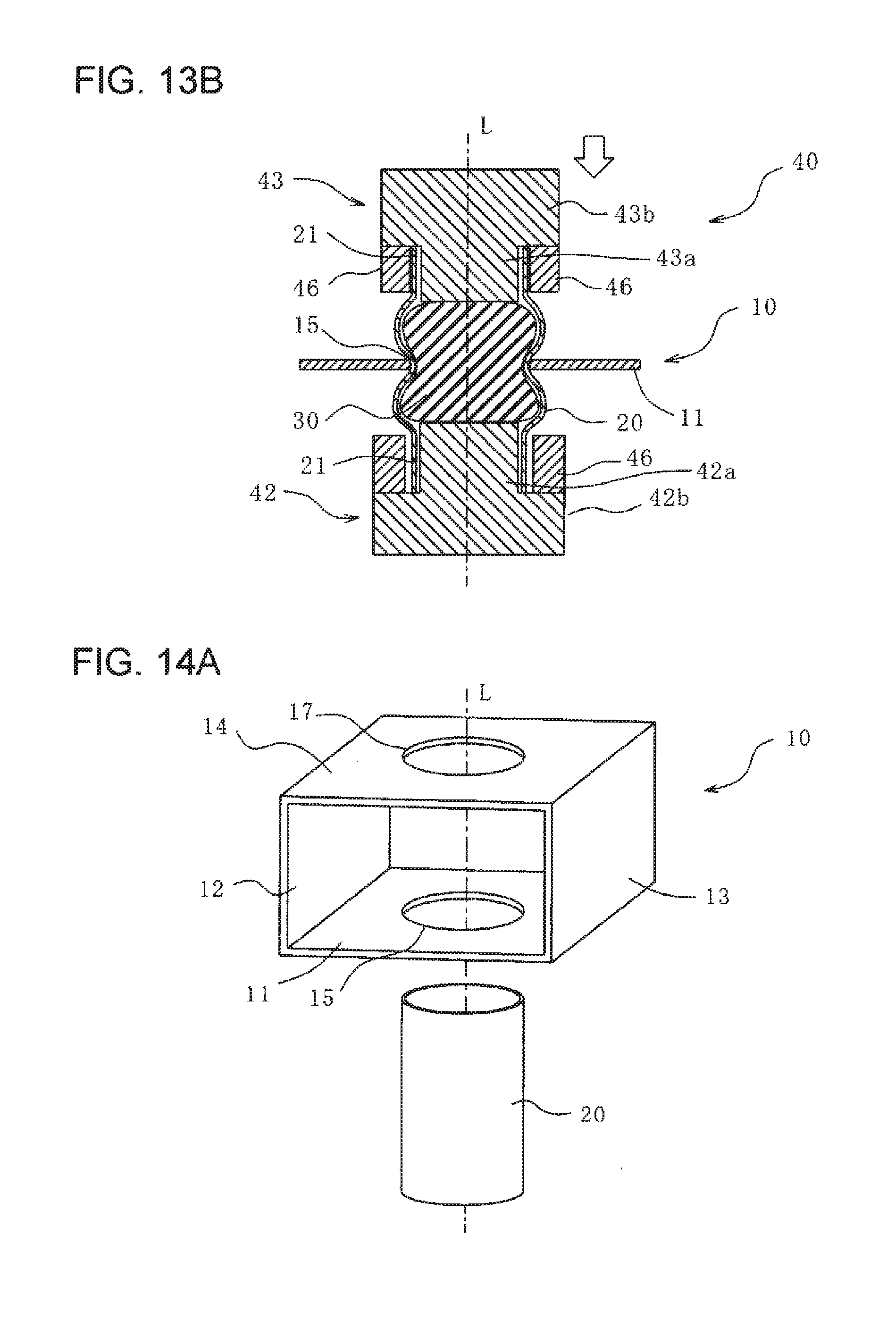
[0067] FIG. 13B is a cross-sectional view illustrating a state after the clinching process performed by using the indenter equipped with the outer frame in accordance with the modification of the fifth embodiment of the present invention.
[0068] FIG. 14A is a perspective view of a steel component having a circular hole and an aluminum pipe having a circular cross-sectional shape when the two are clinched together at two locations in accordance with a sixth embodiment of the present invention.
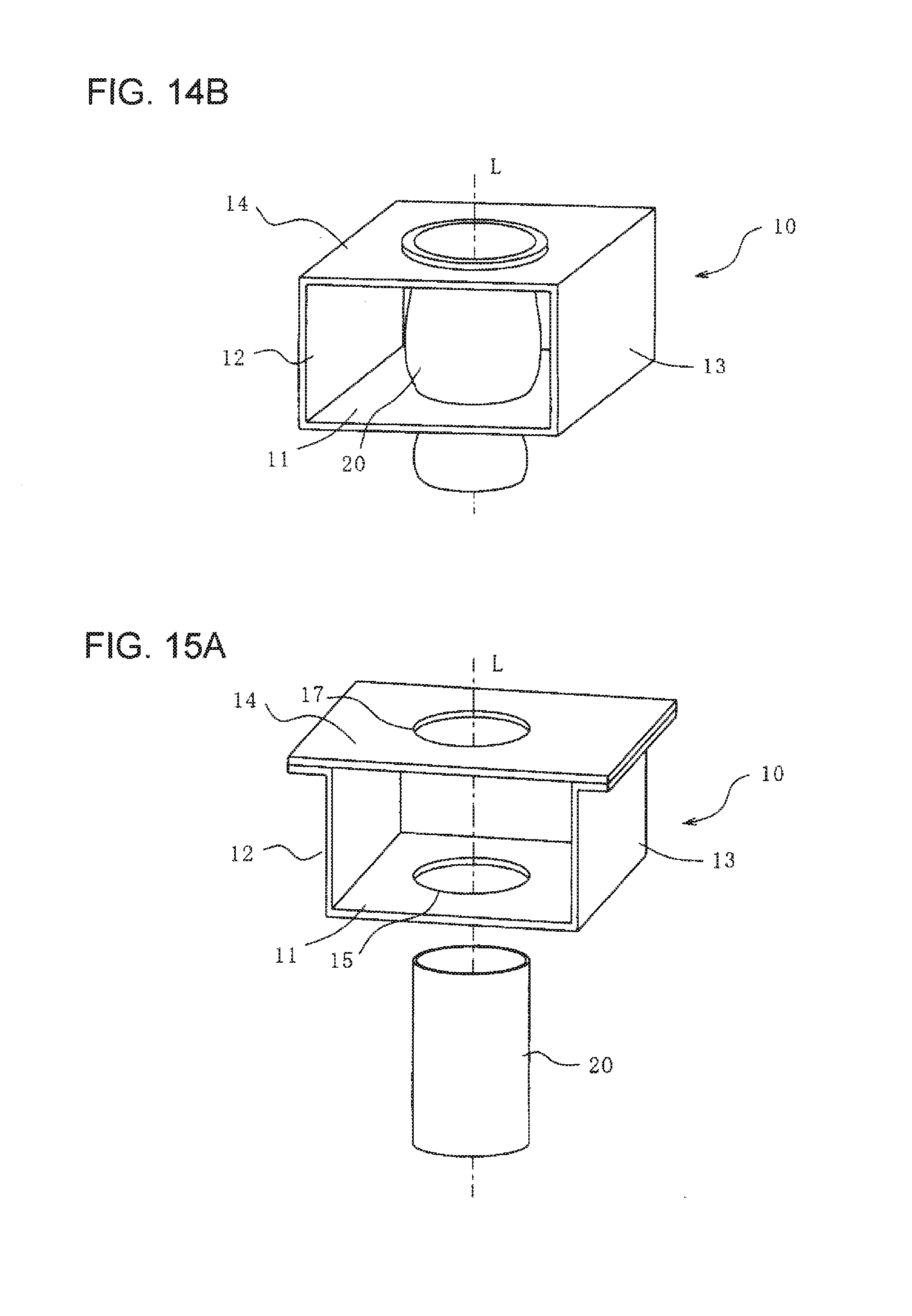
[0069] FIG. 14B is a perspective view of a steel component having a rectangular hole and an aluminum pipe having a rectangular cross-sectional shape when the two are clinched together at two locations in accordance with the sixth embodiment of the present invention.
[0070] FIG. 15A is a perspective view of a hat-channel-type steel component having a circular hole and an aluminum pipe having a circular cross-sectional shape when the two are clinched together at two locations in accordance with a modification of the sixth embodiment of the present invention.
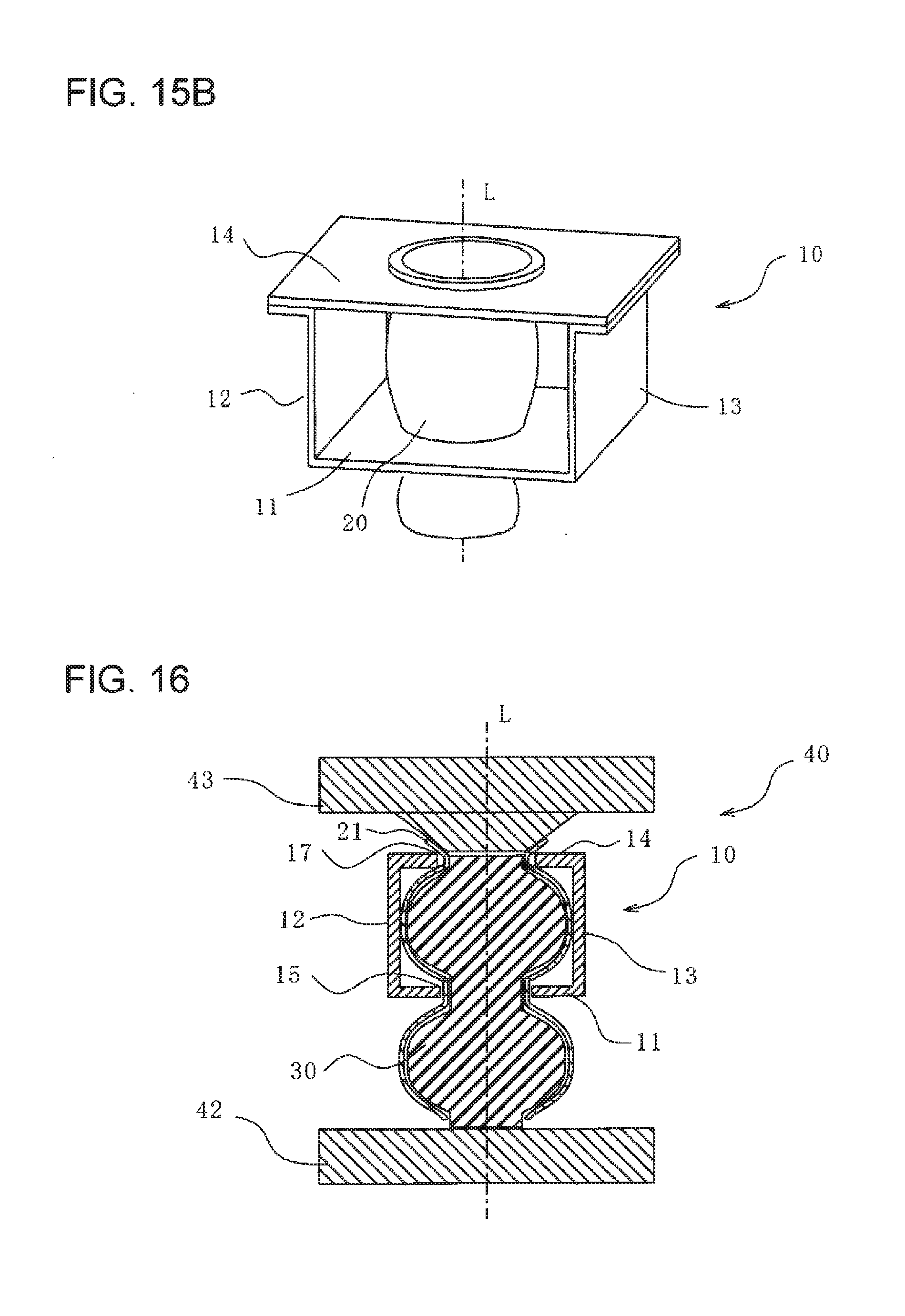
[0071] FIG. 15B is a perspective view of a hat-channel-type steel component having a rectangular hole and an aluminum pipe having a rectangular cross-sectional shape when the two are clinched together at two locations in accordance with a modification of the sixth embodiment of the present invention.
[0072] FIG. 16 is a cross-sectional view illustrating a state where the clinching process in FIGS. 15A and 15B is being performed.
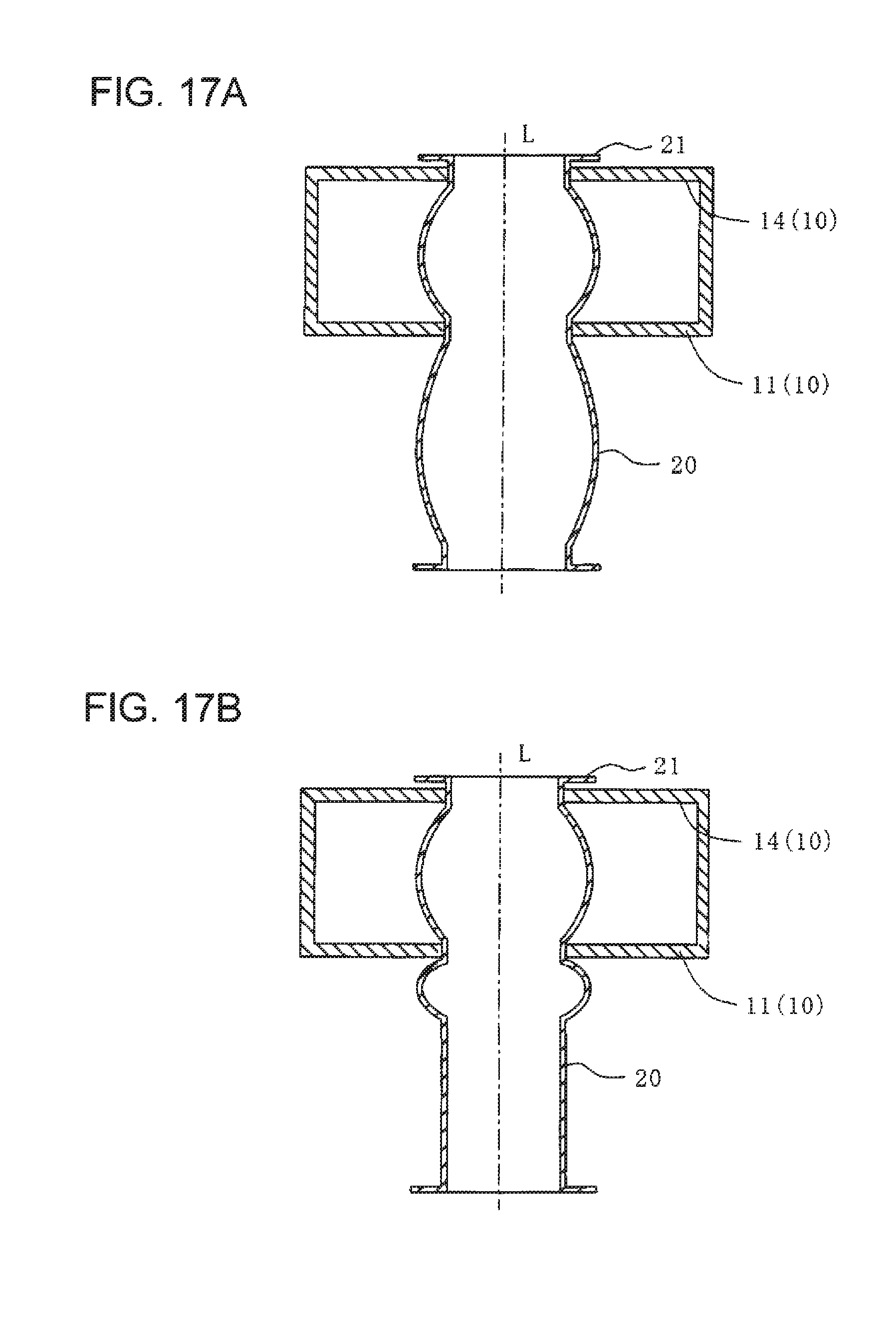
[0073] FIG. 17A is a cross-sectional view illustrating a state after the clinching process in FIG. 16A.
[0074] FIG. 17B is a cross-sectional view illustrating a state after the clinching process in FIG. 16A is performed by partial expansion.
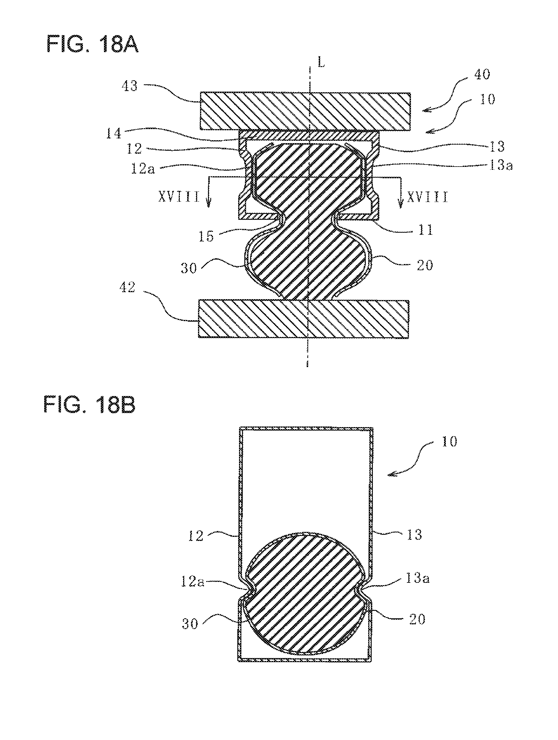
[0075] FIG. 18A is a cross-sectional view illustrating a state after a steel component and an aluminum pipe are clinched together at surfaces having bead sections in accordance with a modification of a seventh embodiment of the present invention.
[0076] FIG. 18B is a cross-sectional view taken along line XVIII-XVIII in FIG. 18A.
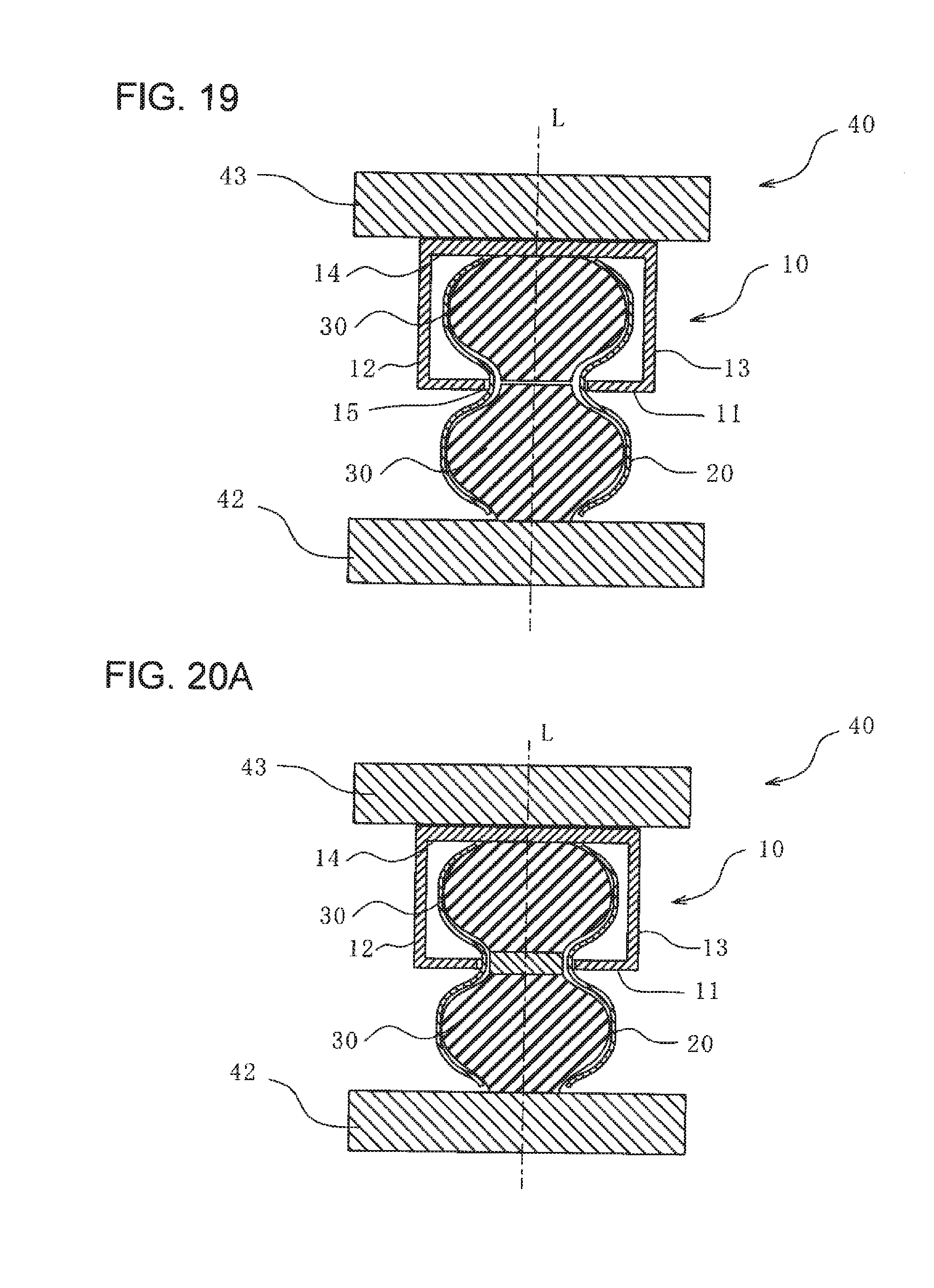
[0077] FIG. 19 is a cross-sectional view illustrating a state after a clinching process performed by using split rubber pieces according to an eighth embodiment of the present invention.
[0078] FIG. 20A is a cross-sectional view illustrating a state after a clinching process performed by inserting a plate between split rubber pieces in accordance with a modification of the eighth embodiment of the present invention.
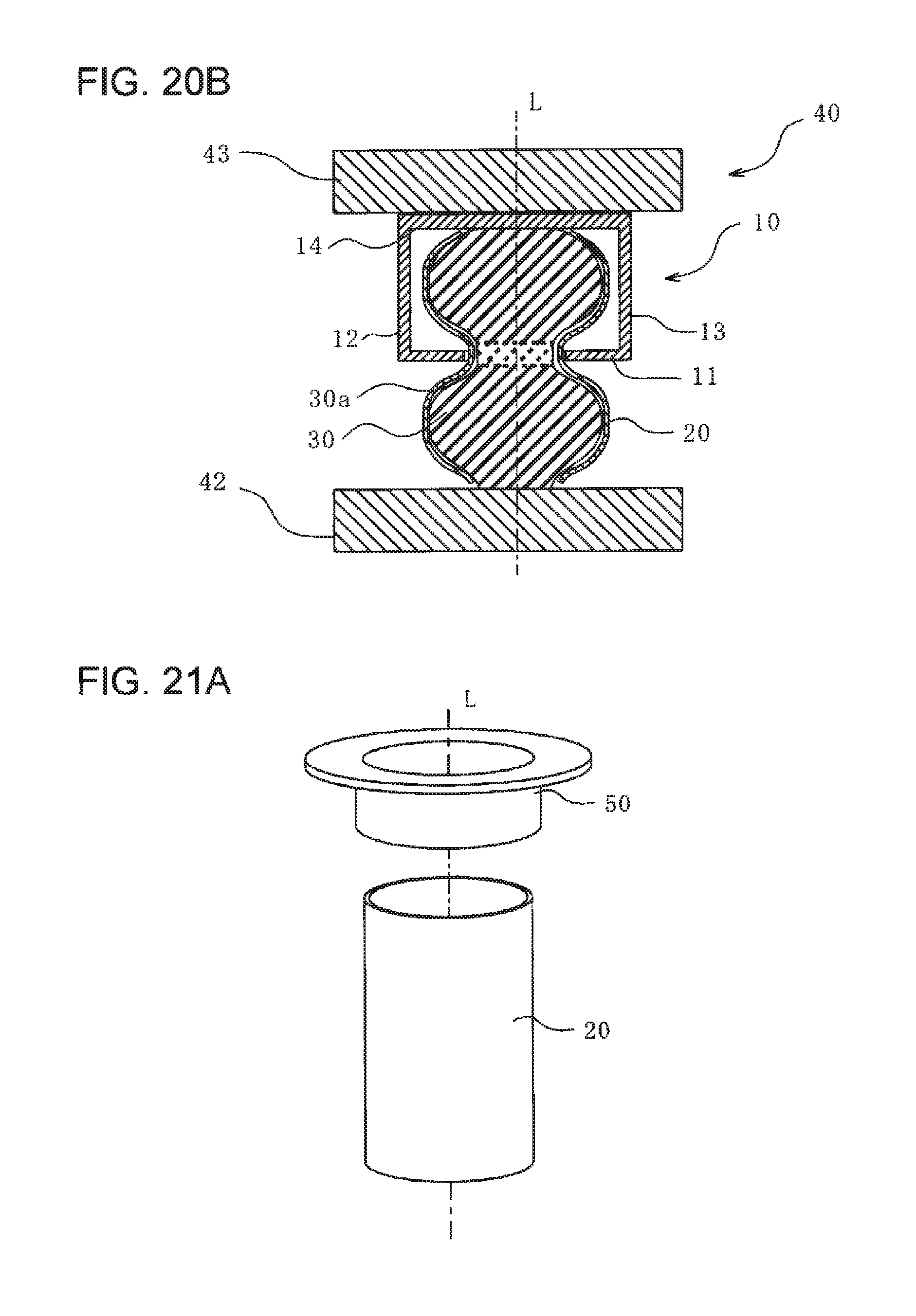
[0079] FIG. 20B is a cross-sectional view illustrating a state after a clinching process performed by using a rubber piece with a different hardness at a joining section in accordance with a modification of the eighth embodiment of the present invention.
[0080] FIG. 21A is a perspective view illustrating a state before a resinous tube component and an aluminum pipe according to a ninth embodiment of the present invention are clinched together.
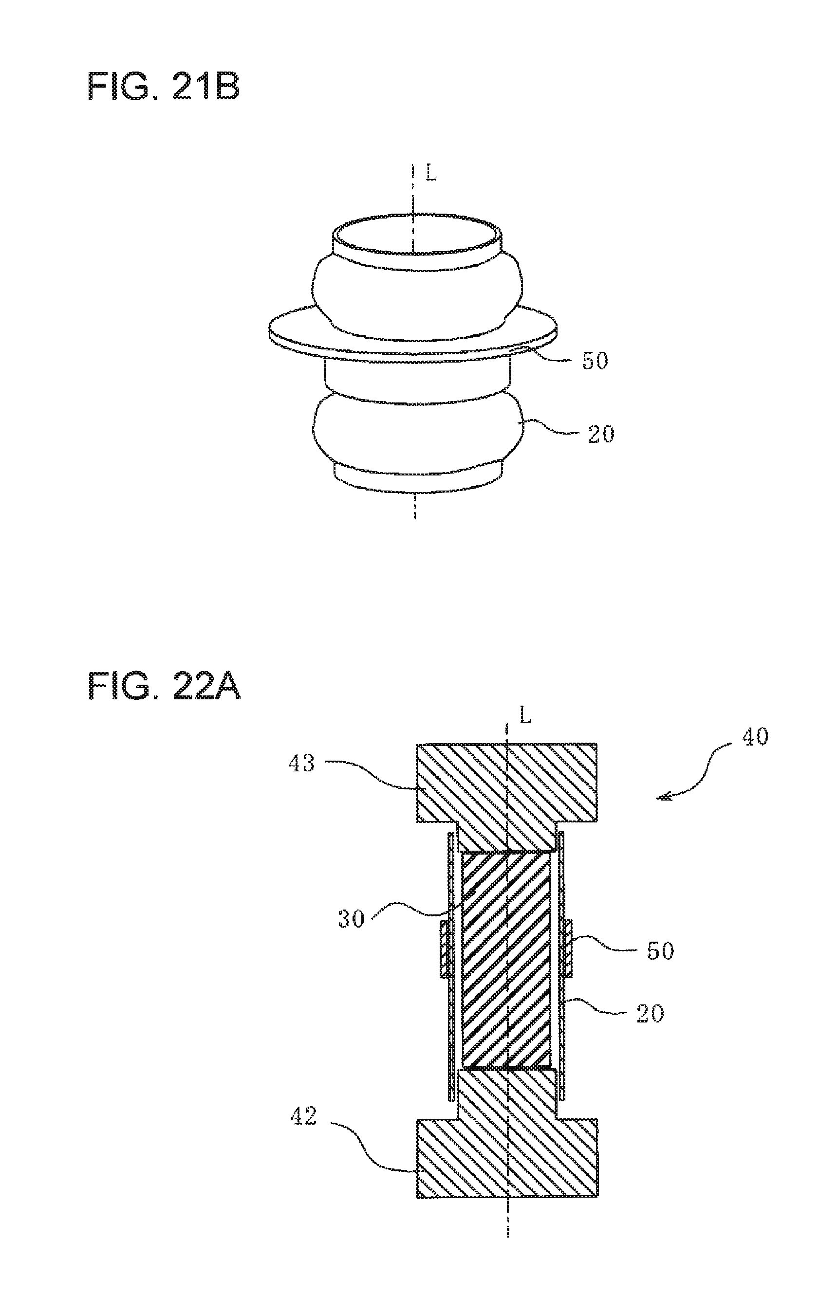
[0081] FIG. 21B is a perspective view illustrating a state after the resinous tube component and the aluminum pipe in FIG. 21A are clinched together.
[0082] FIG. 22A is a cross-sectional view illustrating the state before the resinous tube component and the aluminum pipe in FIG. 21A are clinched together.
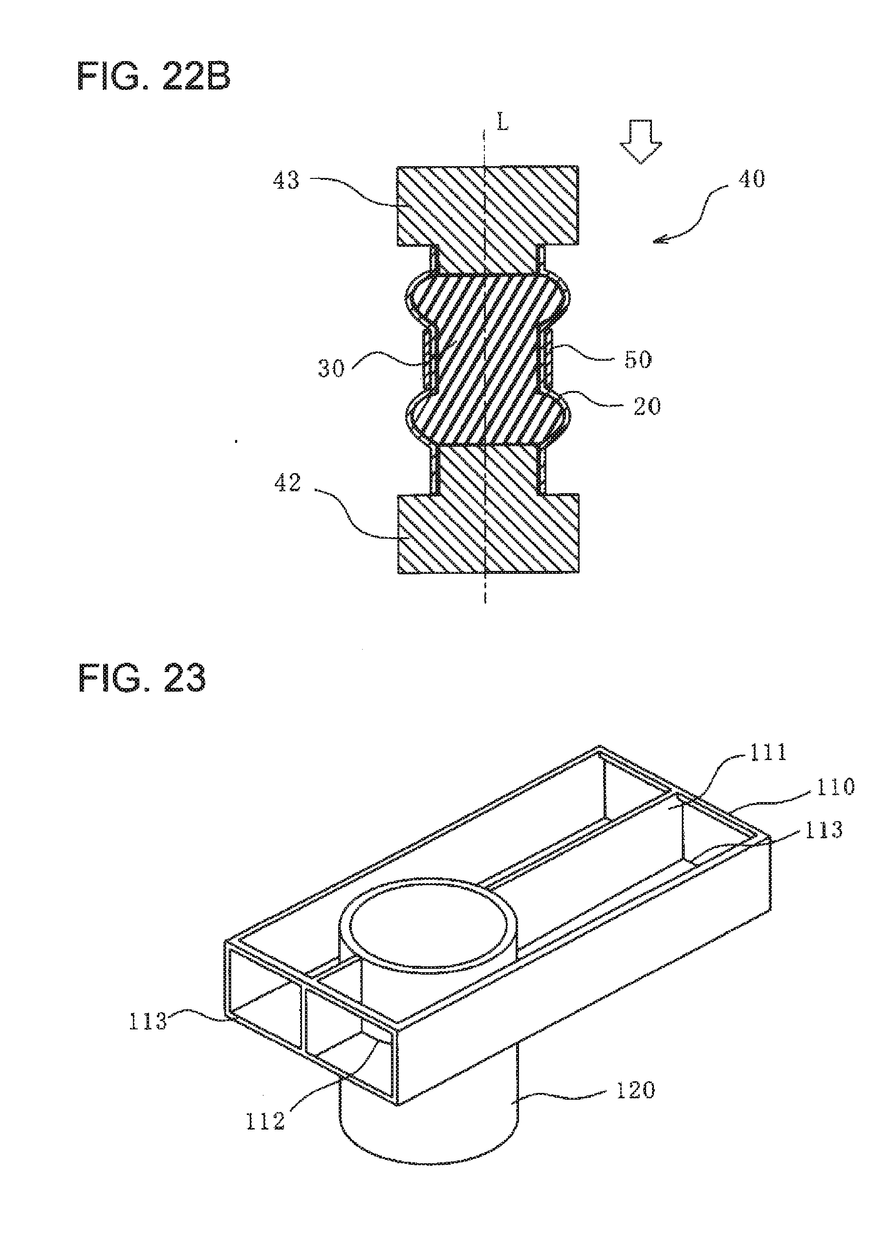
[0083] FIG. 22B is a cross-sectional view illustrating the state after the resinous tube component and the aluminum pipe in FIG. 21A are clinched together.
[0084] FIG. 23 is a perspective view of a steel bumper beam and an aluminum stay according to a tenth embodiment of the present invention.
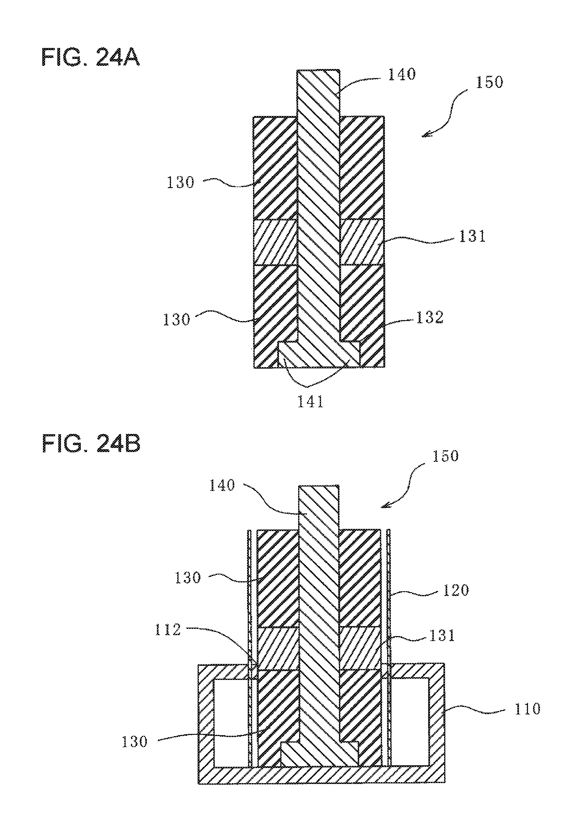
[0085] FIG. 24A is a cross-sectional view of a bulging jig according to the tenth embodiment of the present invention.
[0086] FIG. 24B is a cross-sectional view of a steel bumper beam and an aluminum stay having the bulging jig inserted therein, according to the tenth embodiment of the present invention.
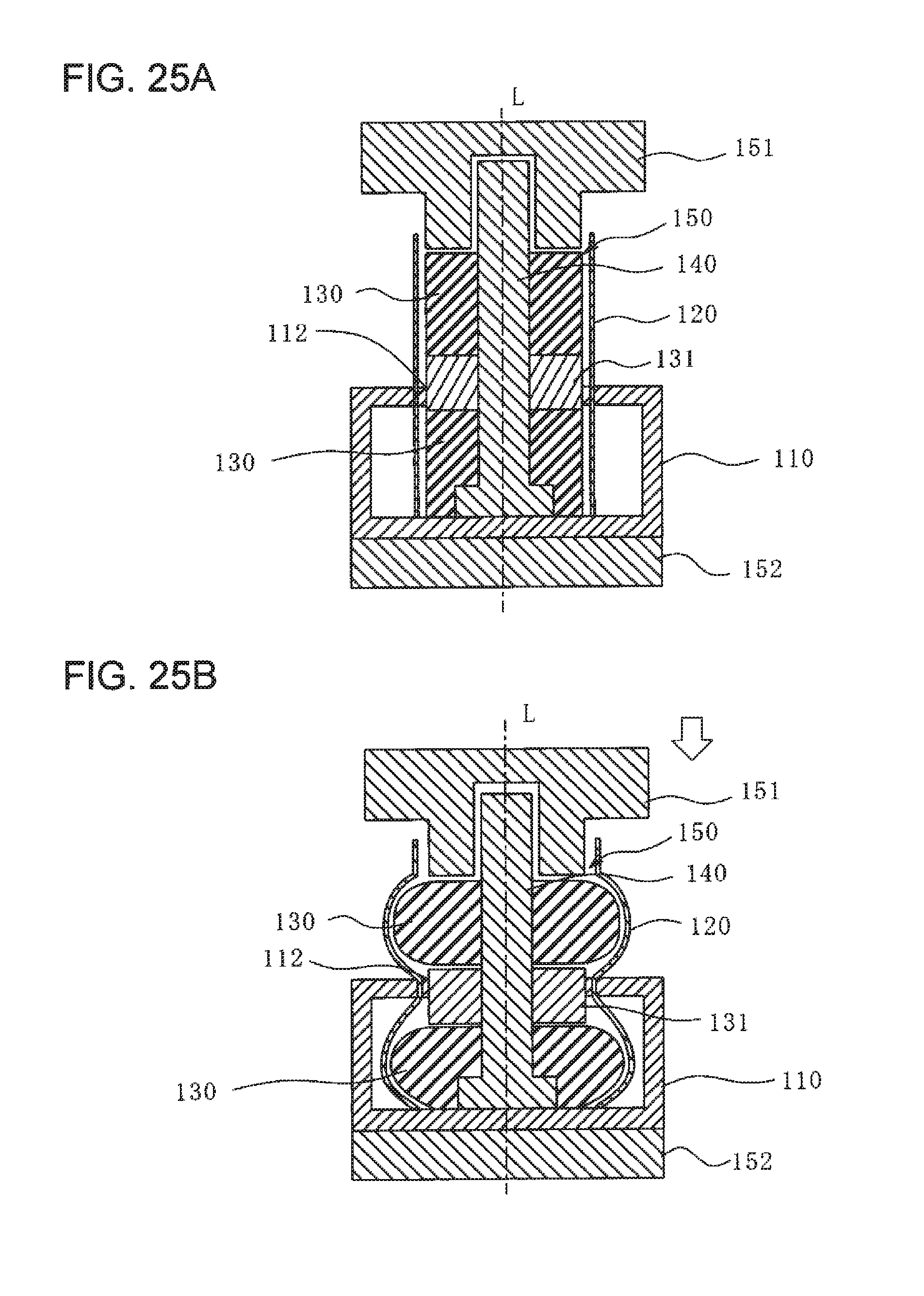
[0087] FIG. 25A is a cross-sectional view illustrating a state before a clinching process according to the tenth embodiment of the present invention.
[0088] FIG. 25B is a cross-sectional view illustrating a state after the clinching process according to the tenth embodiment of the present invention.
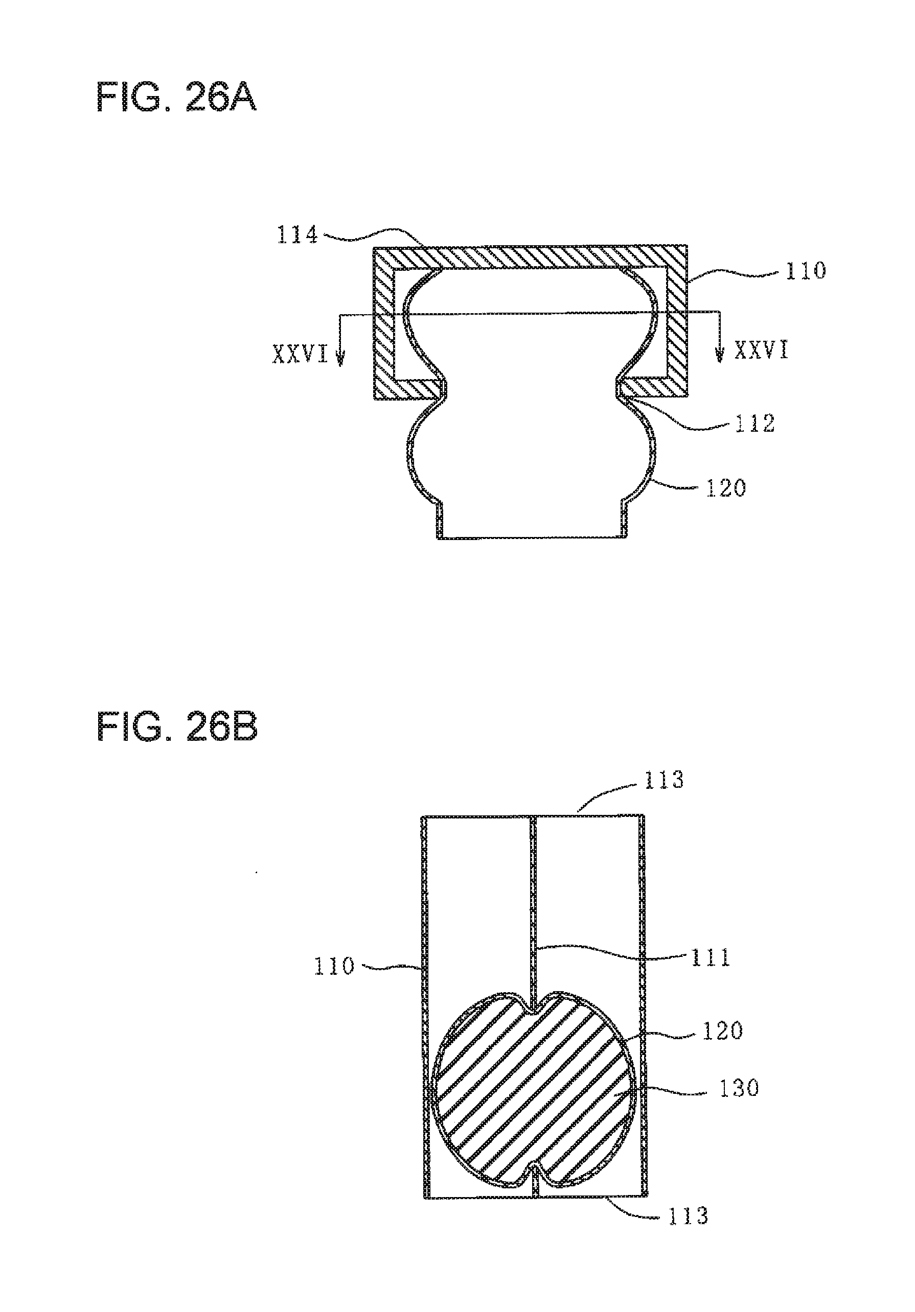
[0089] FIG. 26A is a cross-sectional view illustrating a state where the bulging jig has been removed after the clinching process according to the tenth embodiment of the present invention.
[0090] FIG. 26B is a cross-sectional view taken along line XXVI-XXVI in FIG. 26A.
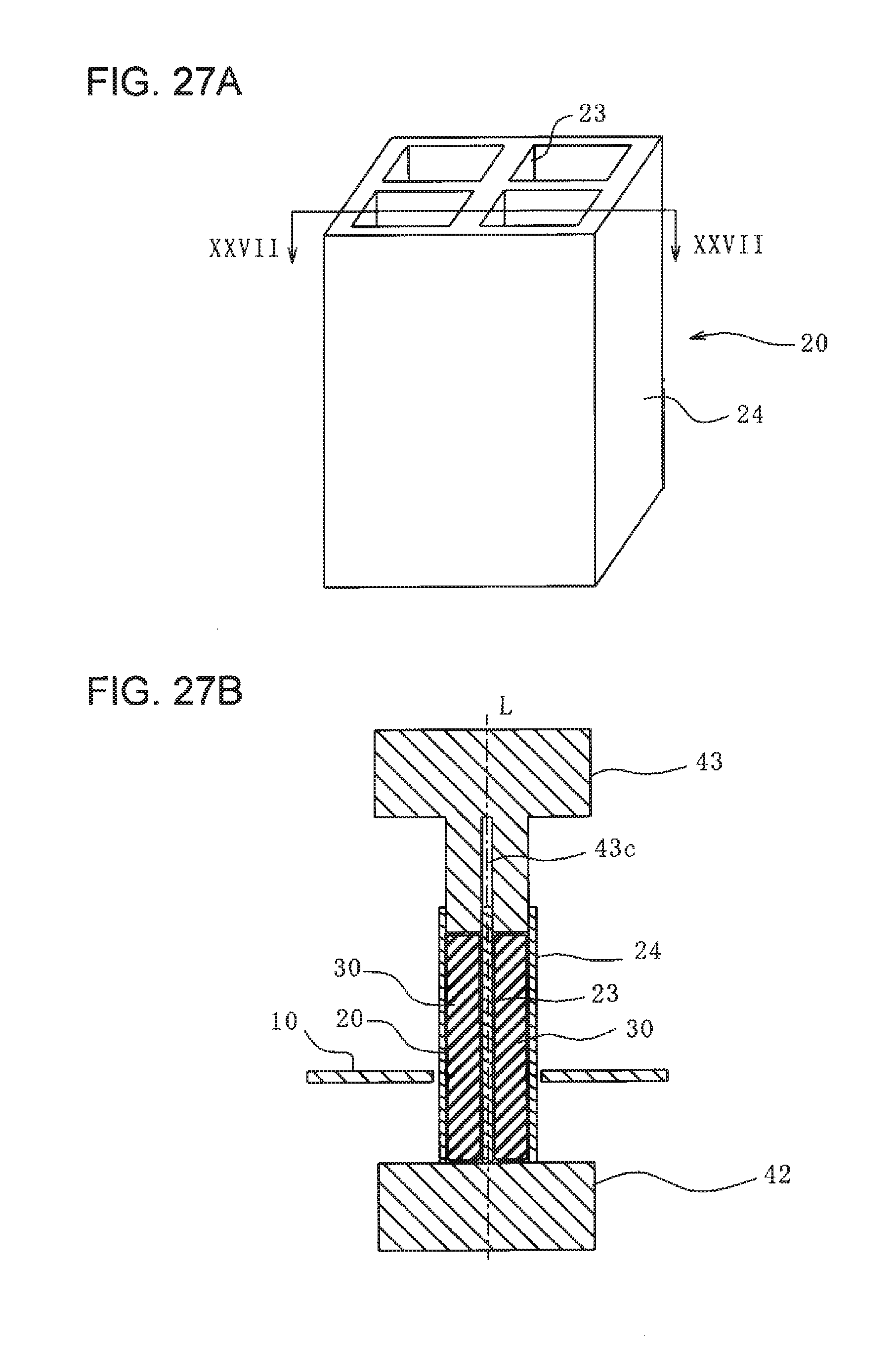
[0091] FIG. 27A is a perspective view of an aluminum pipe according to an eleventh embodiment of the present invention.
[0092] FIG. 27B is a cross-sectional view illustrating a state before a clinching process, taken along line XXVI-XXVI in FIG. 27A.
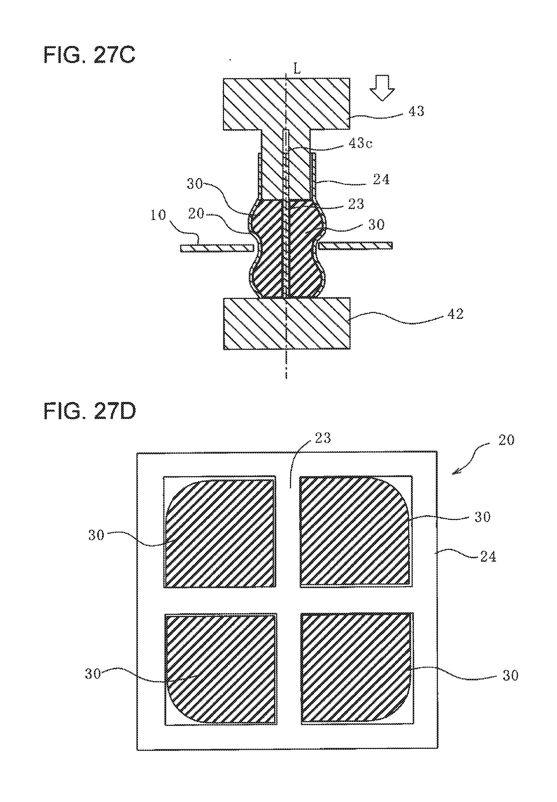
[0093] FIG. 27C is a cross-sectional view illustrating a state after the clinching process, taken along line XXVI-XXVI in FIG. 27A.
[0094] FIG. 27D is a plan view of the aluminum pipe and rubber pieces according to the eleventh embodiment of the present invention.
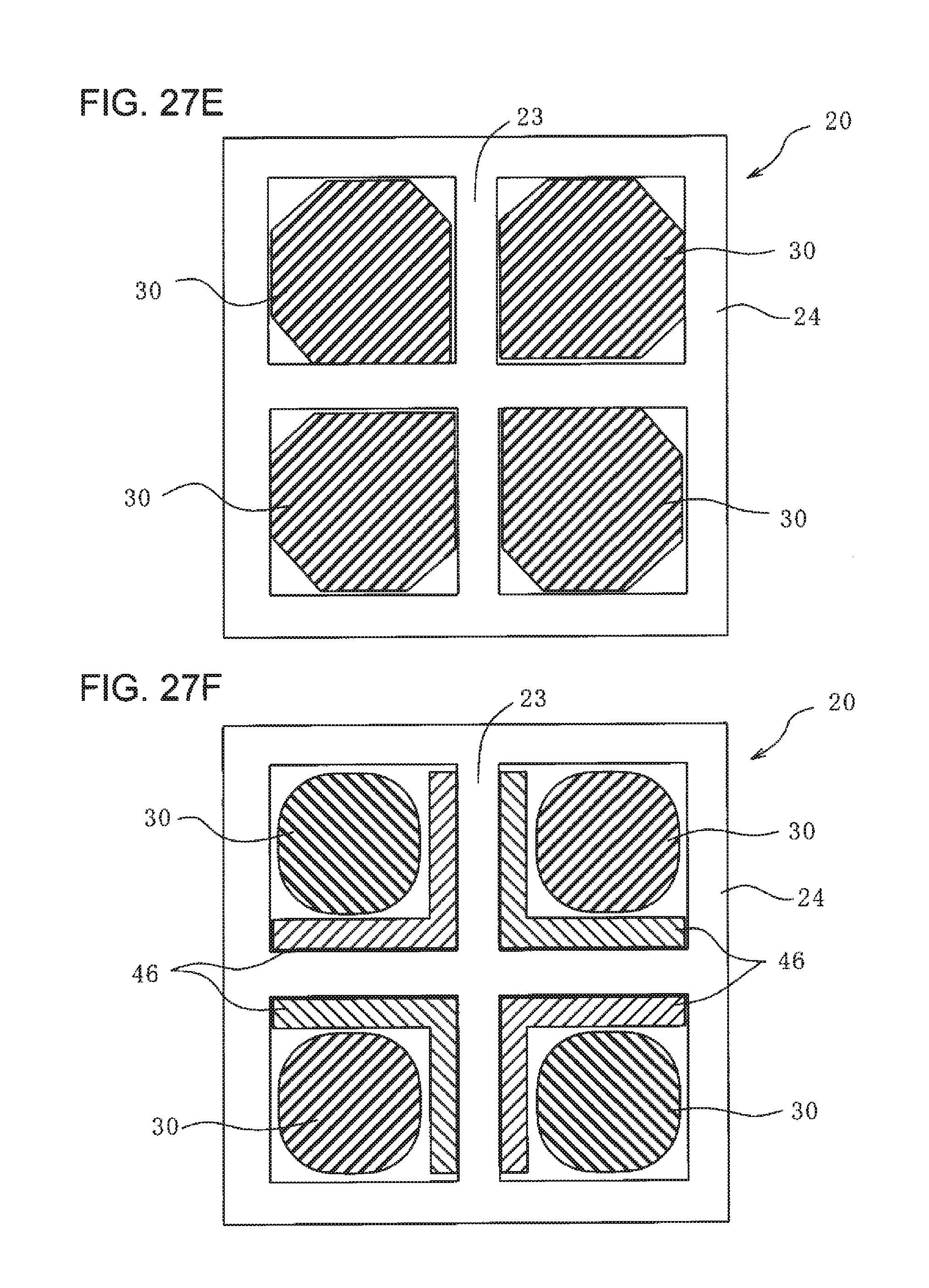
[0095] FIG. 27E is a plan view of the aluminum pipe and rubber pieces with a different shape, according to the eleventh embodiment of the present invention.
[0096] FIG. 27F is a plan view of the aluminum pipe, rubber pieces, and L-shaped angles according to the eleventh embodiment of the present invention.
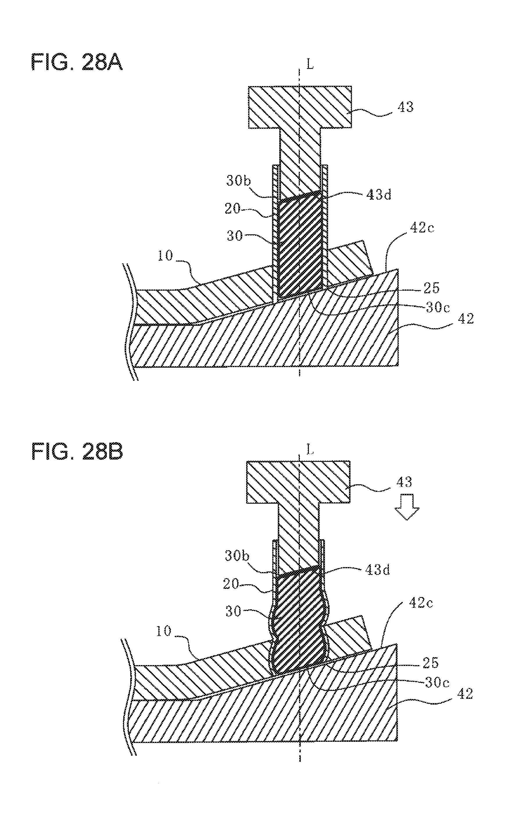
[0097] FIG. 28A is a cross-sectional view illustrating a state before a clinching process according to a twelfth embodiment of the present invention.
[0098] FIG. 28B is a cross-sectional view illustrating a state after the clinching process according to the twelfth embodiment of the present invention.
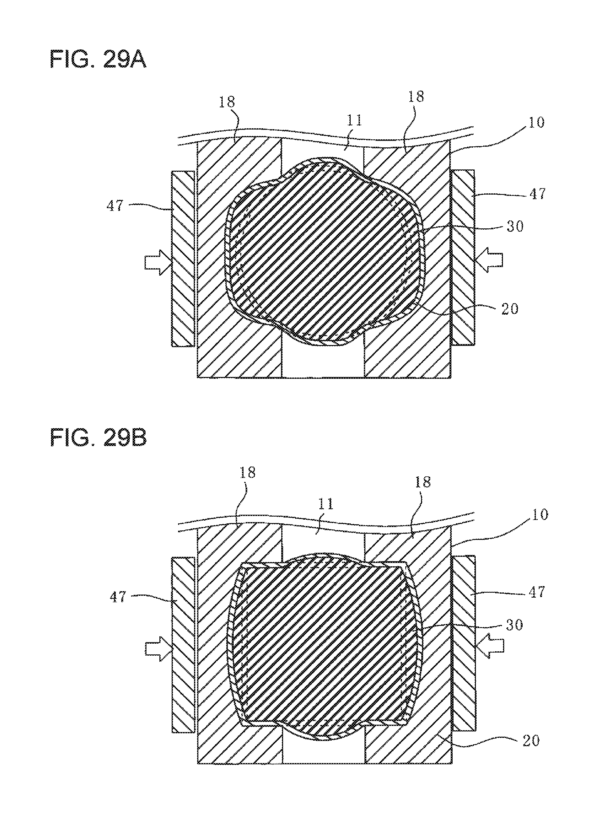
[0099] FIG. 29A is a plan view illustrating a state before and after a clinching process according to a thirteenth embodiment of the present invention.
[0100] FIG. 29B is a plan view illustrating a state before and after the clinching process according to the thirteenth embodiment of the present invention.
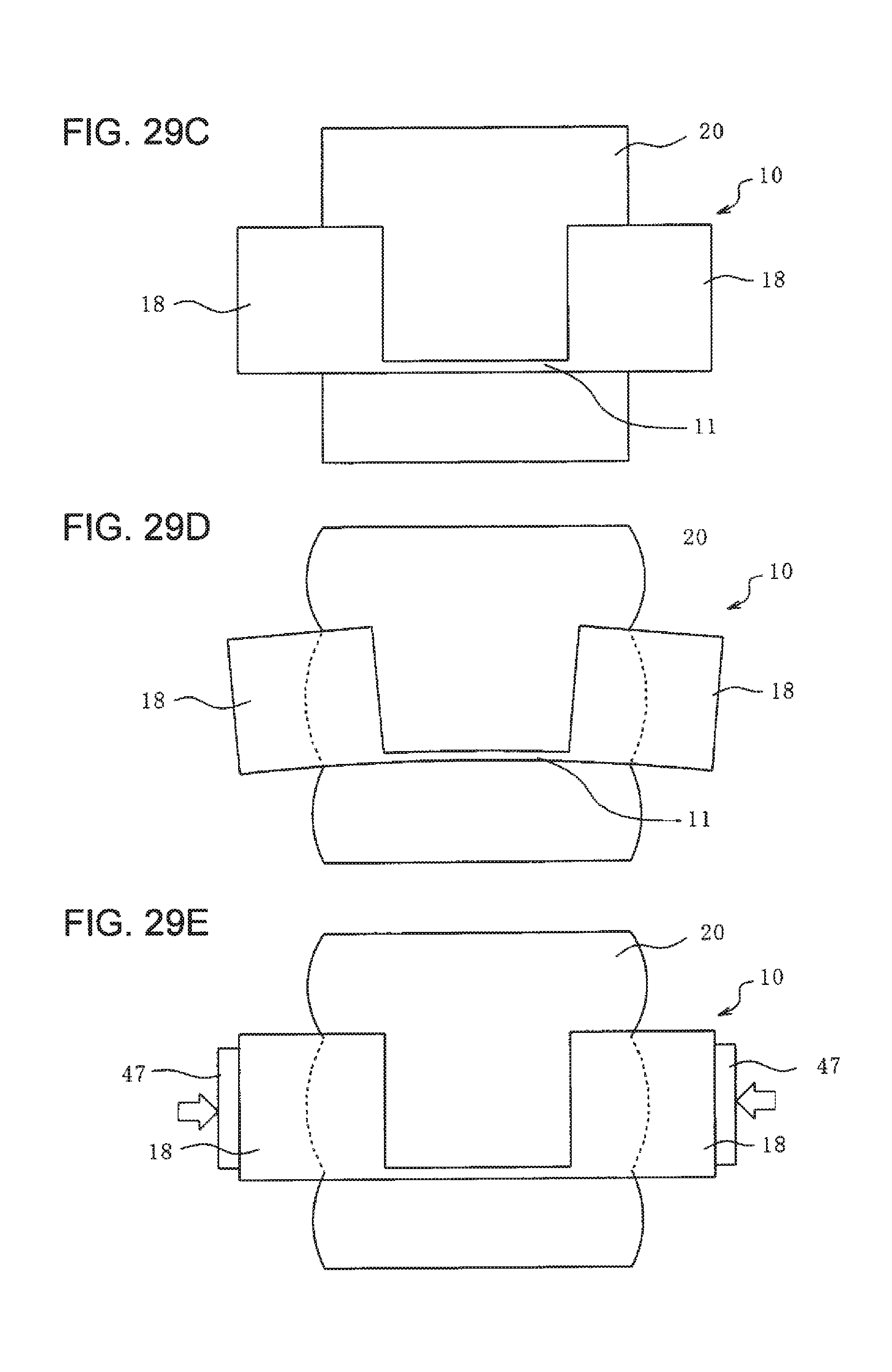
[0101] FIG. 29C is a front view illustrating a state before the clinching process according to the thirteenth embodiment of the present invention.
[0102] FIG. 29D is a front view illustrating a state after the clinching process when a fixation jig according to the thirteenth embodiment of the present invention is not used.
[0103] FIG. 29E is a front view illustrating a state after the clinching process when the fixation jig according to the thirteenth embodiment of the present invention is used.
DESCRIPTION OF EMBODIMENTS
[0104] Embodiments of the present invention will be described below with reference to the appended drawings. In the following description, terms that express directions and positions (such as "upper side" and "lower side") are sometimes used, but these terms are used for providing an easier understanding of the present invention and are not to limit the technical scope of the invention. Furthermore, the following description merely relates to examples of embodiments of the present invention and is not intended to limit the application or the purpose of the invention.
[0105] Although materials of individual components are exemplified in the embodiments described below, the materials of the components in all of the embodiments are particularly not limited to the exemplified materials, and the present invention is applicable to arbitrary materials.
First Embodiment
[0106] A method for joining a steel component (first member) 10 and an aluminum pipe (second member) 20 together by clinching will be described with reference to FIGS. 1A to 2D.
[0107] As shown in FIG. 1A, the steel component 10 is composed of high-tensile steel and has a shape of a channel. The steel component 10 includes a bottom wall (first section) 11, two side walls 12 and 13 extending vertically upward from the base wall 11, and upper walls 14 extending horizontally outward from the two side walls 12 and 13. The bottom wall 11 is provided with a hole (first hole) 15 in which the aluminum pipe 20 is fittable. The aluminum pipe 20 is composed of an aluminum alloy, has a hollow and circular cross-sectional shape, and extends along an axis L. The axis L extends through the center of the aluminum pipe 20 and through the center of the hole 15 in the steel component 10.
[0108] As shown in FIG. 1B, with regard to the aluminum pipe 20 and the steel component 10, the aluminum pipe 20 expands from the inner side toward the outer side so that an upper edge 21 thereof in the drawing is pressed and bent, whereby the aluminum pipe 20 becomes clinched to the hole 15 in the steel component 10. The hole 15 in the steel component 10 preferably has a shape analogous to the cross-sectional shape of the aluminum pipe 20 and a size that is as small as possible within a range in which the aluminum pipe 20 is fittable therein.
[0109] The steel component 10 and the aluminum pipe 20 are clinched together in accordance with the following procedure.
[0110] As shown in FIGS. 2A to 2D, the steel component 10 and the aluminum pipe 20 are clinched together by using a rubber piece (elastic body) 30.
[0111] First, as shown in FIG. 2A, the aluminum pipe 20 is fitted into the hole 15 in the steel component 10, the rubber piece 30 is inserted into the aluminum pipe 20, and the components are set in a pressing device 40. Alternatively, the aluminum pipe 20 may be fitted into the hole 15 in a state where the rubber piece 30 is inserted in the aluminum pipe 20. The pressing device 40 includes an indenter 43 and a strike plate 42. The indenter 43 has a flat lower surface and uses the lower surface to press against the steel component 10 or the rubber piece 30. The strike plate 42 has a flat upper surface, and the steel component 10 and the rubber piece 30 are placed on the upper surface. The rubber piece 30 has a columnar shape with a diameter that allows it to be insertable into the aluminum pipe 20, and has an overall length that is larger than that of the aluminum pipe 20. Therefore, when in the set state, the rubber piece 30 partially protrudes from the upper end of the aluminum pipe 20. Thus, when the pressing device 40 begins pressing such that the strike plate 42 and the indenter 43 relatively approach each other, the rubber piece 30 is pressed first. However, the rubber piece 30 does not necessarily have to protrude from the upper end of the aluminum pipe 20, and may alternatively be flush with the upper end of the aluminum pipe 20 or be accommodated therein.
[0112] Next, as shown in FIG. 2B, the pressing device 40 applies a compressive external force to the rubber piece 30 along the axis L. The rubber piece 30 dimensionally enlarges in the diameter direction as its size decreases along the axis L. Accordingly, the rubber piece 30 is caused to elastically deform (expand) outward from the axis L, thereby causing the aluminum pipe 20 to expand. Then, as shown in FIG. 2C, the aluminum pipe 20 is further expanded by being further compressed by the pressing device 40. At the same time, the upper edge 21 in the drawing is pressed and bent toward the steel component 10, so that the aluminum pipe 20 becomes clinched to the steel component 10.
[0113] After the clinching process, the rubber piece 30 from which the compressive force of the pressing device 40 has been removed restores its original shape with its own elastic force, as shown in FIG. 2D, so that the rubber piece 30 can be readily removed from the aluminum pipe 20.
[0114] According to this method, the rubber piece 30 is expanded outward so that the aluminum pipe 20 expands uniformly, thereby preventing local deformation and reducing the load on the members 10 and 20. This is because the aluminum pipe 20 can be uniformly deformed by utilizing the properties in which the rubber piece 30 compressed along the axis L expands uniformly from the inner side toward the outer side. Therefore, fit accuracy can be improved, thereby achieving increased joint strength. Moreover, this is an easier method, as compared with an electromagnetic forming method or other machining methods.
[0115] An electromagnetic forming method is usable only on electrically conductive materials and has limitations with respect to cross-sectional shapes and dimensions depending on coils to be used. In contrast, this method is not dependent on materials and has no limitations related to cross-sectional shapes and dimensions. Moreover, since the method is executable in a facility that applies a compressive force to the rubber piece 30, an electrical facility that requires a large-capacity capacitor, as in the electromagnetic forming method, is not necessary.
[0116] According to this method, two members can be joined together, so that a multi-material process can be readily executed at low cost. Therefore, as described above, this method can be used on members composed of various materials other than the two components composed of high-tensile steel and an aluminum alloy. The same applies to the subsequent embodiments.
[0117] The material used as the rubber piece 30 to be inserted into the aluminum pipe 20 is preferably, for example, urethane rubber, chloroprene rubber, CNR rubber (chloroprene rubber+nitrile rubber), or silicon rubber. Moreover, it is preferable that the rubber piece 30 have a Shore A hardness of 30 or higher.
[0118] A member to be inserted into the aluminum pipe 20 is not limited to the rubber piece 30. For example, as shown in FIGS. 3A and 3B, a fluid sealing member 32 having gas or liquid sealed therein may be used in place of the rubber piece 30. Other members that expand outward in accordance with a compressive force so as to expand the aluminum pipe 20 are also usable. It is preferable that the member deforms uniformly like the rubber piece 30 when expanding outward in response to a compressive force.
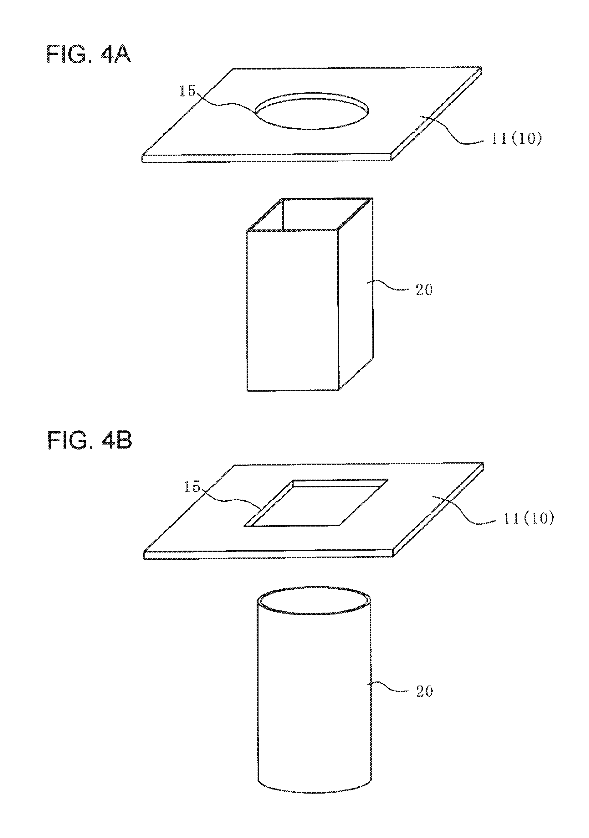
[0119] Furthermore, as shown in FIGS. 4A and 4B, the shape and size of the hole 15 provided in the bottom wall 11 of the steel component 10 do not have to be analogous to the cross-sectional shape of the aluminum pipe 20 to be fitted thereto. Specifically, a steel component 10 having a circular hole 15 and an aluminum pipe 20 having a rectangular cross-sectional shape may be clinched together as in FIG. 4A, or a steel component 10 having a rectangular hole 15 and an aluminum pipe 20 having a circular cross-sectional shape may be clinched together as in FIG. 4B.
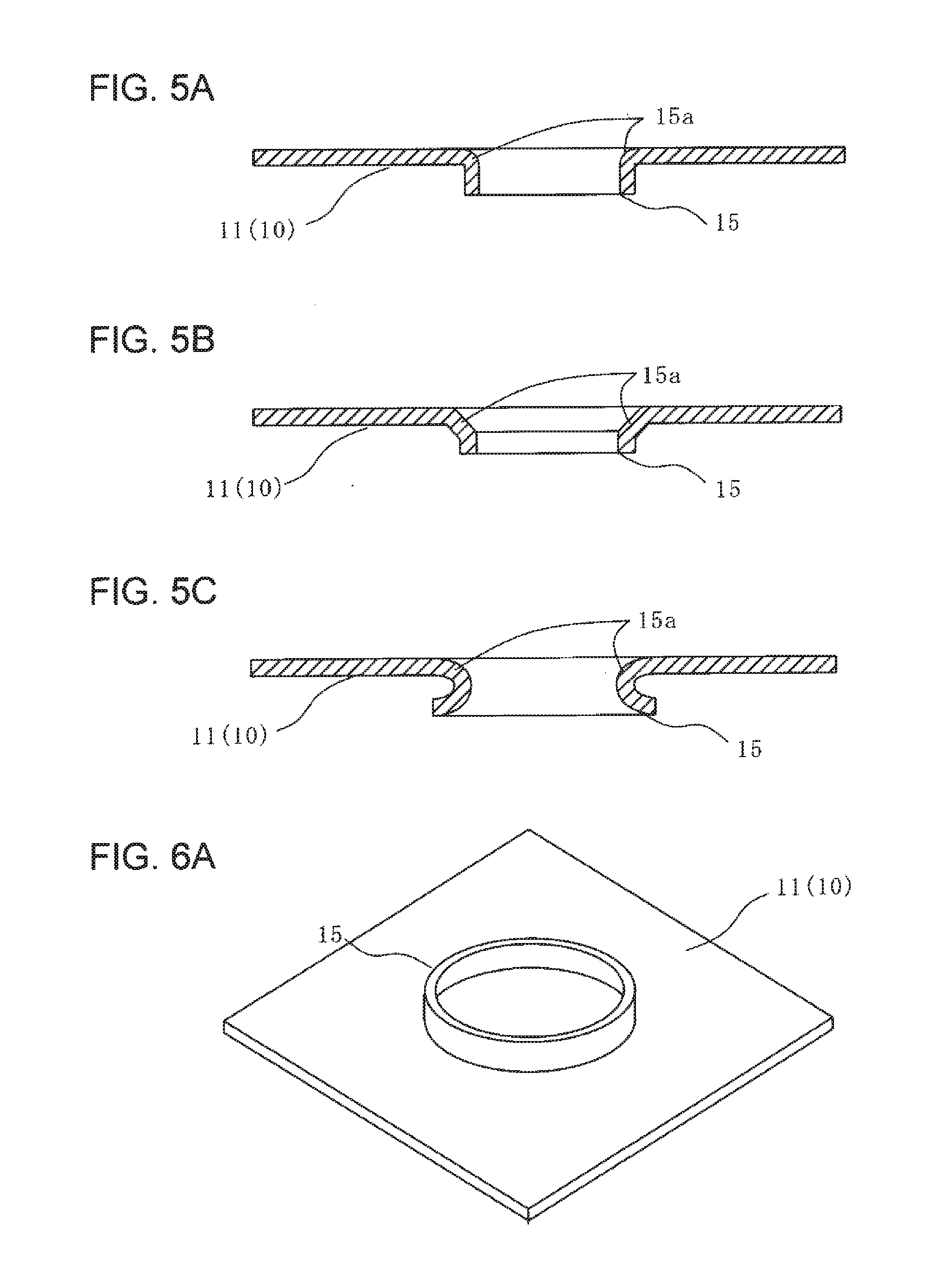
[0120] Furthermore, as shown in FIGS. 5A to 5C, a burring process (flange-up process) may be performed on the hole 15 for preventing deformation of the steel component 10, for reducing damages to the aluminum pipe 20, and for increasing the clinching strength. Conceivable shapes obtained as a result of the burring process include, for example, various cross-sectional shapes shown in FIGS. 5A to 5C. In FIG. 5A, a shoulder section 15a has a large radius. In FIG. 5B, the shoulder section 15a is chamfered. In FIG. 5C, a rolling process is employed. Accordingly, even in a case where the steel component 10 has high strength, cracking of the steel component 10 as a result of machining can be effectively prevented.
[0121] The burring process may be performed in the upward direction or the downward direction in the drawings. Preferably, as indicated by a two-dot chain line in FIG. 2A, the burring process is performed in the downward direction in the drawing such that a part that is bent as a result of the burring process does not appear on the top surface of the steel component 10.
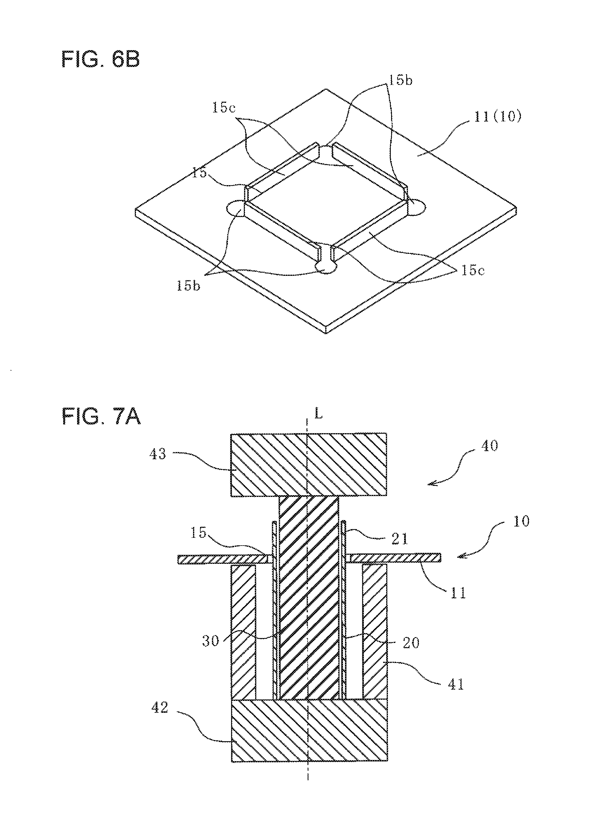
[0122] As shown in FIGS. 6A and 6B, there are various conceivable shapes, such as a circular shape (see FIG. 6A) or a rectangular shape (see FIG. 6B), for the hole 15 that is to undergo the burring process. In particular, in a case where the hole 15 is polygonal, corner sections 15b may be cut out, and only straight side sections 15c may be bent upward, as shown in FIG. 6B, so that the corner sections 15b can be prevented from cracking.
Second Embodiment
[0123] A joining method according to this embodiment shown in FIGS. 7A and 7B is similar to that in the first embodiment in FIGS. 2A to 2D except for a feature related to an outer-frame mold 41. Therefore, parts identical to those in the configuration shown in FIGS. 2A to 2D will be given the same reference signs, and descriptions thereof will be omitted.
[0124] As shown in FIG. 7A, in this embodiment, the steel component 10 and the aluminum pipe 20 are clinched together by using the outer-frame mold 41. The outer-frame mold 41 has a cylindrical shape concentric with the aluminum pipe 20. The outer-frame mold 41 is disposed between the strike plate 42 and the steel component 10 and at the outer side of the aluminum pipe 20. When set in the pressing device 40, the aluminum pipe 20 and the outer-frame mold 41 have a gap therebetween. By applying pressure using the indenter 43 in this state, the aluminum pipe 20 can conform to the shape of the inner surface of the outer-frame mold 41 when the aluminum pipe 20 expands, as shown in FIG. 7B.
[0125] According to this method, as shown in FIGS. 8A to 8C, the inner surface of the outer-frame mold 41 may have various polygonal shapes, such as a hexagonal shape (see FIG. 8B) or a cross shape (see FIG. 8C), in addition to the cylindrical shape (see FIG. 8A). With regard to these shapes, an appropriate shape can be selected in view of, for example, component performance. For example, if the aluminum pipe 20 is a bumper stay, which is one of automobile components, the inner surface of the outer-frame mold 41 may be given small recesses and protrusions so that these small recesses and protrusions are transferred onto the aluminum pipe 20, thereby achieving enhanced performance for absorbing impact energy in the event of a collision.
Third Embodiment
[0126] A joining method according to this embodiment shown in FIGS. 9A to 10B is similar to that in the first embodiment in FIGS. 2A to 2D except for a feature related to an expanding region 22 of the aluminum pipe 20. Therefore, parts identical to those in the configuration shown in FIGS. 2A to 2D will be given the same reference signs, and descriptions thereof will be omitted.
[0127] As shown in FIG. 9A, in this embodiment, the rubber piece 30 to be inserted into the aluminum pipe 20 is reduced in length, such that the rubber piece 30 is disposed only near the joining section of the aluminum pipe 20. Moreover, the strike plate 42 has a columnar protrusion 42a extending upward. The protrusion 42a is inserted into the aluminum pipe 20 and supports the rubber piece 30. In other words, the lower end of the rubber piece 30 is in contact with the upper end of the protrusion 42a, and the upper end of the rubber piece 30 is in contact with the lower end of the indenter.
[0128] According to this method, an outward expanding force does not act on the part where the rubber piece 30 is not disposed. Thus, as shown in FIG. 9B, the expanding region 22 of the aluminum pipe 20 is limited, so that the aluminum pipe 20 and the steel component 10 can be clinched together by causing only the region near the joining section of the aluminum pipe 20 to expand. Selection of whether the aluminum pipe 20 is to be substantially entirely deformed as in the first and second embodiments described above or whether the aluminum pipe 20 is to be partially deformed as in this embodiment may be made, as appropriate, based on, for example, the relationship with the component performance.
[0129] As shown in FIGS. 10A and 10B, a cylindrical outer-frame mold 44 that regulates expansion of the aluminum pipe 20 may be disposed therearound. The outer-frame mold 44 has, at the upper end thereof, a large-diameter section 44a with a large inner diameter near the joining section so as to expand only near the joining section. The inner diameter excluding that of the large-diameter section 44a is substantially equal to the outer diameter of the aluminum pipe 20. Therefore, by using the outer-frame mold 44, the expanding region 22 can be controlled with high accuracy such that the aluminum pipe 20 expands only near the joining section.
Fourth Embodiment
[0130] A joining method according to this embodiment shown in FIGS. 11A and 11B is similar to that in the third embodiment in FIGS. 10A and 10B except for a feature related to the shape of the indenter 43. Therefore, parts identical to those in the configuration shown in FIGS. 10A and 10B will be given the same reference signs, and descriptions thereof will be omitted.
[0131] As shown in FIG. 11A, the indenter 43 included in the pressing device 40 according to this embodiment has a downwardly-tapered truncated-cone shape and has a protrusion 43a and a brim 43b. Sometimes, a high forming force is required for expanding the edge 21 of the aluminum pipe 20 protruding upward from the steel component 10, and there are cases where the clinching is insufficient with the deformation of the rubber piece 30 alone or the durability of the rubber piece 30 may become a problem due to large deformation thereof. In such cases, the method according to this embodiment is effective.
[0132] As shown in FIG. 11B, at the final stage of the forming process, the upper edge 21 of the aluminum pipe 20 protruding upward from the steel component 10 is pressed and expanded outward directly by the protrusion 43a of the indenter 43 without the intervention of the rubber piece 30, and is further bent toward the steel component 10. This enables more secure clinching. Moreover, the durability of the rubber piece 30 is improved since excessive load does not act on the rubber piece 30.
Fifth Embodiment
[0133] A joining method according to this embodiment shown in FIGS. 12A and 12B is similar to that in the first embodiment in FIGS. 2A to 2D except for a feature related to the shapes of the indenter 43 and the strike plate 42. Therefore, parts identical to those in the configuration shown in FIGS. 2A to 2D will be given the same reference signs, and descriptions thereof will be omitted.
[0134] As shown in FIG. 12A, in this embodiment, the strike plate 42 includes a columnar protrusion 42a extending upward and a brim 42b provided around the protrusion 42a. The indenter 43 includes a columnar protrusion 43a extending downward and a brim 43b provided around the protrusion 43a. The protrusions 42a and 43a are inserted in the aluminum pipe 20.
[0135] As shown in FIG. 12B, when performing pressing, the brims 42b and 43b come into contact with the respective ends of the aluminum pipe 20. Thus, the brims 42b and 43b apply compressive forces along the axis L onto the aluminum pipe 20.
[0136] According to this method, the aluminum pipe 20 is also compressed along the axis L so as to assist with outward expansion of the aluminum pipe 20. Specifically, together with the expanding force applied by the rubber piece 30 from the inner side of the aluminum pipe 20, the aluminum pipe 20 can be expanded more reliably, thereby enabling clinching.
[0137] As shown in FIGS. 13A and 13B, it is also effective to dispose an outer frame 45 at the outer side of a part of the aluminum pipe 20 that is not to be expanded (i.e., the edge 21 in this embodiment). The outer frame 45 is cylindrical and is disposed around the edge 21 of the aluminum pipe 20. By disposing the outer frame 45, deformation of the edge 21 of the aluminum pipe 20 is regulated, so that a shape according to the intended use can be obtained.
Sixth Embodiment
[0138] A joining method according to this embodiment shown in FIGS. 14A to 17B is similar to that in the first embodiment in FIGS. 2A to 2D except for a feature related to the number of joining sections. Therefore, parts identical to those in the configuration shown in FIGS. 2A to 2D will be given the same reference signs, and descriptions thereof will be omitted.
[0139] As shown in FIG. 14A, in this embodiment, the steel component 10 and the aluminum pipe 20 are clinched together at two locations. The steel component 10 includes a bottom wall 11, an upper wall (second section) 14 disposed parallel to the bottom wall 11, and two side walls 12 and 13 connecting these walls, all of which constitute a closed cross section. The bottom wall 11 is provided with a hole 15 (first hole). The upper wall 14 is provided with a hole 17 (second hole). As shown in FIG. 14B, the aluminum pipe 20 is clinched to these two holes 15 and 17.
[0140] FIG. 16 is a cross-sectional view during a clinching process. In the clinching process performed on the two holes 15 and 17, the indenter 43 is used to press and bend the edge 21 of the aluminum pipe 20 toward the steel component 10 as in the first embodiment, and the aluminum pipe 20 is further expanded so as to be clinched to the upper hole 17 in the drawing. The aluminum pipe 20 is clinched to the lower hole 15 in the drawing by being simply expanded.
[0141] By performing clinching at two locations as in this embodiment, the joint strength can be further increased, as compared with the case where clinching is performed at a single location. In particular, the clinching method using the rubber piece 30 is the same as the case where clinching is performed at a single location in terms of the facility used, and is thus effective since the method can easily be used when performing clinching at a plurality of locations.
[0142] The shape of the steel component 10 or the aluminum pipe 20 when performing clinching at two locations is not limited to the above. For example, the steel component 10 may have a hat-channel shape, as shown in FIGS. 15A and 15B, or another shape.
[0143] Furthermore, as shown in FIG. 17A, the entire aluminum pipe 20 may be freely expanded when performing the clinching process. By using the outer-frame mold 44 described with reference to FIGS. 7A and 7B, only the regions of the aluminum pipe 20 near the joining sections may be clinched by being expanded, as shown in FIG. 17B.
Seventh Embodiment
[0144] A joining method according to this embodiment shown in FIGS. 18A and 18B is similar to that in the sixth embodiment in FIG. 16 except for features related to joining locations and bead sections 12a and 13a. Therefore, parts identical to those in the configuration shown in FIG. 16 will be given the same reference signs, and descriptions thereof will be omitted.
[0145] As shown in FIGS. 18A and 18B, in the steel component 10 according to this embodiment, the two side walls 12 and 13 are respectively provided with the bead sections 12a and 13a. The bead sections 12a and 13a are inward protrusions and extend along the axis L. The aluminum pipe 20 is entirely clinched to the hole 15 in the bottom wall 11 and to the bead sections 12a and 13a of the two side walls 12 and 13.
[0146] As shown in FIG. 18B, the aluminum pipe 20 and the steel component 10 are clinched together by including the bead sections 12a and 13a of the side walls 12 and 13 so that the joint strength can be further increased. Moreover, because the aluminum pipe 20 and the steel component 10 are clinched together by including the bead sections 12a and 13a, rotation of the aluminum pipe 20 relative to the steel component 10 can be regulated. Accordingly, the bead sections 12a and 13a are effective for preventing the aluminum pipe 20 from rotating. Alternatively, for preventing the aluminum pipe 20 from rotating, it is also effective to give the edge of the hole 15 a cutout shape or a shape other than the circular shape.
Eighth Embodiment
[0147] A joining method according to this embodiment shown in FIG. 19 is similar to that in the seventh embodiment in FIG. 18A except for a feature related to split rubber pieces 30. Therefore, parts identical to those in the configuration shown in FIG. 18A will be given the same reference signs, and descriptions thereof will be omitted.
[0148] As shown in FIG. 19, in this embodiment, the rubber piece 30 is split near the hole 15. According to this method, the rubber piece 30 is split at the hole 15, that is, at the joining section, so that deformation of the hole 15 and the bottom wall 11 of the steel component 10 can be prevented. Specifically, because the rubber piece 30 is split, an expanding force is not applied to the hole 15, so that the hole 15 and the bottom wall 11 can maintain their original shapes.
[0149] Furthermore, as shown in FIGS. 20A and 20B, it is preferable that a tabular plate 31 be inserted between the rubber pieces 30 split at the joining section and inserted in the aluminum pipe 20. The plate 31 may be composed of metal or resin so long as it is strong enough not to deform in response to a compressive force received from the rubber piece 30, and preferably has a thickness of 15 mm or smaller.
[0150] According to this method, the plate 31 exists in the joining section so that deformation of the hole 15 and the bottom wall 11 of the steel component 10 can be prevented more reliably. Because the plate 31 does not expand, an expanding force is not applied to the hole 15, so that the hole 15 and the bottom wall 11 can maintain their original shapes.
[0151] As an alternative to FIG. 20A in which the rubber piece 30 is split and the plate 31 is disposed between the split pieces, a rubber piece 30 partially composed of a different material may be used, as in FIG. 20B. In FIG. 20B, the rubber piece is a non-split single piece but has a high-hardness section 30a near the joining section. Specifically, the rubber piece 30 has a high hardness only in a part thereof near the joining section. Thus, this high-hardness section 30a has a function similar to that of the plate 31, so that the hole 15 and the bottom wall 11 can maintain their original shapes.
Ninth Embodiment
[0152] A joining method according to this embodiment shown in FIGS. 21A to 22B is similar to that in the fifth embodiment in FIGS. 9A and 9B except that the steel component 10 is replaced with a cylindrical resinous tube component 50. Therefore, parts identical to those in the configuration shown in FIGS. 9A and 9B will be given the same reference signs, and descriptions thereof will be omitted.
[0153] As shown in FIGS. 21A and 21B, in this embodiment, the cylindrical resinous tube component 50 having a flange at the upper end thereof and the aluminum pipe 20 are clinched together. Like the resinous tube component 50, the target member does not have to be tabular or be composed of metal. As mentioned above, the aluminum pipe 20 deforms outward in response to a compressive force applied along the axis L from the rubber piece 30 so as to expand. Therefore, this method is not limited to be used on electrically conductive materials, as in the electromagnetic forming method, and can also be used on resin materials, and the shape is not limited to the tabular shape.
[0154] FIGS. 22A and 22B are cross-sectional views illustrating states before and after the resinous tube component and the aluminum pipe in FIG. 21A are clinched together. As shown in FIGS. 22A and 22B, the aluminum pipe 20 is clinched to the cylindrical resinous tube component 50 by being expanded at the opposite ends thereof.
Tenth Embodiment
[0155] An example in which the present invention is applied to a bumper, which is one of automobile components, will now be described.
[0156] As shown in FIG. 23, a cylindrical aluminum stay (second member) 120 is clinched to a closed-cross-section steel bumper beam (first member) 110 having a partition 111 in the middle. The steel bumper beam 110 has openings 113 and 113 at opposite sides thereof. The openings 113 and 113 are separated from each other by the partition 111. For illustrative purposes, a top plate 114 (see FIG. 26A) of the steel bumper beam 110 is shown in a removed state in FIG. 23. As shown in FIG. 24A, for the implementation, a bulging jig 150 including a round-rod-shaped rubber piece 130, a tabular steel plate 131, and a narrow round rod 140 composed of steel is used. A through-hole 112 into which the narrow round rod 140 is insertable is provided in the middle of the rubber piece (elastic body) 130 and the tabular plate 131. One end of the round rod 140 is provided with a brim 141 for preventing the rubber piece 130 from falling out. The rubber piece 130 is split into two, one of which is provided with a countersunk hole 132 to which the brim 141 of the round rod 140 is fittable. The tabular plate 131 is placed on the rubber piece 130 with the countersunk hole 132 facing downward, the other rubber piece 130 is placed thereon, and the round rod 140 is subsequently inserted from below. The plate 131 has a circular shape with an outer diameter of .PHI.83.5 mm and a thickness of 10 mm. The rubber pieces 130 used are composed of urethane rubber and have a circular shape with an outer diameter of .PHI.83.5 mm, a length of 50 mm, and a Shore A hardness of 90.
[0157] FIG. 24B illustrates a state where the aluminum stay 120 is fitted in the hole (hole) 112 (see FIG. 23) provided in the steel bumper beam 110, and the aforementioned bulging jig 150 is inserted in the aluminum stay 120. As shown in FIG. 23, the steel bumper beam 110 is processed into a closed-cross-sectional shape having a partition 111 in the middle by roll-forming a 1470-MPa-class cold-rolled steel plate having a thickness of 1.4 mm and has a circular hole 112 having an outer diameter of .PHI.90.2 mm formed in the joining section with the aluminum stay 120. In this case, the partition 111 in the middle is partially removed. The aluminum stay 120 is formed of a circular pipe composed of an aluminum alloy A6063 and having a thickness of 3 mm, an outer diameter of .PHI.90 mm, and a length of 150 mm.
[0158] Next, a clinching process shown in FIGS. 25A and 25B will be described. FIG. 25A illustrates a state where the steel bumper beam 110, the aluminum stay 120, and the bulging jig 150 are set on a lower mold 152, and a presser jig 151 is disposed thereon. This state is set in the pressing device 40 (see FIGS. 2A to 2D), and a slide having the presser jig 151 set thereon is lowered so as to apply a compressive force to the rubber pieces 130. In this case, pressure along the axis L of the aluminum pipe 20 is not applied, as shown in FIGS. 9A and 9B.
[0159] FIG. 25B illustrates a state where the slide is at the bottom dead center. The rubber pieces 130 are compressed by the presser jig 151 so as to expand in the horizontal direction, thereby bulge-forming the aluminum stay 120. Because the tabular plate 131 is inserted, the joint surface of the steel bumper beam 110 does not receive an excessive force so that undesired deformation is suppressed, whereby a clinching process with high fit accuracy is completed.
[0160] FIGS. 26A and 26B illustrate the steel bumper beam 110 and the aluminum stay 120 upon completion of the clinching process. FIG. 26A is a cross-sectional view of the steel bumper beam 110 and the aluminum stay 120 in a clinched state, and FIG. 26B is a cross-sectional view taken along line XXVI-XXVI. This embodiment is characterized in that the joint strength is high since clinching can be achieved at the middle partition 111 in addition to clinching at the hole 112 provided in the steel bumper beam 110 due to expansion of the aluminum stay 120 caused by the rubber pieces 130 shown in FIG. 26B.
Eleventh Embodiment
[0161] A joining method according to this embodiment shown in FIGS. 27A to 27F is similar to that in the fifth embodiment in FIGS. 9A and 9B except that the aluminum pipe 20 has a partition wall 23 therein and a plurality of rubber pieces 30 are inserted in the aluminum pipe 20. Therefore, parts identical to those in the configuration shown in FIGS. 9A and 9B will be given the same reference signs, and descriptions thereof will be omitted.
[0162] As shown in FIG. 27A, the aluminum pipe 20 according to this embodiment has outer walls 24 extending along the axis L and having a rectangular shape in cross section and the partition wall 23 provided inside the outer walls 24. The space inside the aluminum pipe 20 is divided into four spaces by the partition wall 23 having a cross shape in plan view. By providing the partition wall 23 in this manner, the strength of the aluminum pipe 20 can be increased. The cross-sectional shape is not limited to the rectangular shape and may be a freely-chosen shape.
[0163] As shown in FIGS. 27B and 27C, the indenter 43 according to this embodiment is provided with a cutout 43c in conformity to the shape of the partition wall 23. By providing the cutout 43c, the clinching process can be completed without interference with the aluminum pipe 20 even when the rubber pieces 30 are pressed.
[0164] Accordingly, because the clinching process is performed by using the plurality of rubber pieces 30 (i.e., four in this embodiment), concentration of stress caused by deformation can be prevented, so that the load on the steel component 10 and the aluminum pipe 20 can be reduced.
[0165] The shape of each rubber piece 30 according to this embodiment is not limited in particular. For example, as shown in FIG. 27D, the corners of the four inserted rubber pieces 30 may be round-chamfered so as to reduce the load on the corners of the aluminum pipe 20, thereby preventing cracking and damaging. As shown in FIG. 27E, C-chamfering may be performed, similarly to round-chamfering. As shown in FIG. 27F, although the shape of the four inserted rubber pieces 30 is columnar, steel L-shaped angles 46 may be disposed along the partition wall 23 within the aluminum pipe 20. Consequently, the load on the partition wall 23 can be reduced, thereby suppressing deformation.
Twelfth Embodiment
[0166] A joining method according to this embodiment shown in FIGS. 28A and 28B is similar to that in the fifth embodiment in FIGS. 9A and 9B except that the steel component 10 and the aluminum pipe 20 are joined together in an inclined state. Therefore, parts identical to those in the configuration shown in FIGS. 9A and 9B will be given the same reference signs, and descriptions thereof will be omitted.
[0167] As shown in FIGS. 28A and 28B, the aluminum pipe 20 according to this embodiment has an end surface 25 inclined relative to the axis L. The steel component 10 is bent and is placed on an inclined surface 42c. The aluminum pipe 20 is placed on the inclined surface 42c in a state where the inclined end surface 25 is in contact therewith, and is clinched to the steel component 10. Therefore, the steel component 10 and the aluminum pipe 20 are clinched together in an inclined state. Opposite end surfaces 30b and 30c of the rubber piece 30 according to this embodiment are formed and disposed parallel to the inclined end surface 25 of the aluminum pipe 20. A pressing surface 43d of the indenter 43 is also formed parallel to the end surfaces 30b and 30c of the rubber piece 30.
[0168] Accordingly, this method can be used for clinching the steel component 10 and the aluminum pipe 20 together in an inclined state, which is often seen from a practical standpoint. Specifically, the opposite end surfaces 30b and 30c of the rubber piece 30 are given the same angle as the joining angle, so that the rubber piece 30 expands uniformly, whereby the aluminum pipe 20 can be expanded uniformly.
Thirteenth Embodiment
[0169] A joining method according to this embodiment shown in FIGS. 29A to 29D is similar to that in the fifth embodiment in FIGS. 9A and 9B except that the steel component 10 is joined in a state where deformation thereof is restrained by a fixation jig 47. Therefore, parts identical to those in the configuration shown in FIGS. 9A and 9B will be given the same reference signs, and descriptions thereof will be omitted.
[0170] As shown in FIGS. 29A and 29B, the steel component 10 according to this embodiment has a bottom wall 11 and an upright wall 18 extending along the axis L from the bottom wall 11. The cross-sectional shape of the aluminum pipe 20 before the clinching process is not particularly limited and may be circular (see the dashed line in FIG. 29A) or rectangular (see the dashed line in FIG. 29B). The fixation jig 47 for suppressing deformation is provided at the outer side of the steel component 10. The fixation jig 47 is disposed along the upright wall 18 and is fixed from the directions of the arrows in the drawings so as not to move outward. Although the fixation jig 47 used in this embodiment is tabular, the shape of the fixation jig 47 is not limited to this shape and may alternatively be a freely-chosen shape that can suppress deformation.
[0171] As shown in FIGS. 29C to 29E, in a case where the fixation jig 47 is not provided, the steel component 10 may deform in a warping manner when clinching is performed (see FIG. 29D). However, with the fixation jig 47, deformation of the steel component 10 is restrained, so that deformation, such as warping, of the steel component 10 caused by expansion of the aluminum pipe 20 can be suppressed (see FIG. 29E).
REFERENCE SIGNS LIST
[0172] 10 steel component (first member) [0173] 11 bottom wall (first section) [0174] 12, 13 side wall [0175] 12a, 13a bead section [0176] 14 upper wall (second section) [0177] 15 hole (first hole) [0178] 15a shoulder section [0179] 15b corner section [0180] 15c straight side section [0181] 17 hole (second hole) [0182] 18 upright wall [0183] 20 aluminum pipe (second member) [0184] 21 edge [0185] 22 expanding region [0186] 23 partition wall [0187] 24 outer wall [0188] 25 end surface [0189] 30 rubber piece (elastic body) [0190] 30a high-hardness section [0191] 30b, 30c end surface [0192] 31 plate [0193] 32 fluid sealing member [0194] 40 pressing device [0195] 41 outer-frame mold [0196] 42 strike plate [0197] 42a protrusion [0198] 42b brim [0199] 42c inclined surface [0200] 43 indenter [0201] 43a protrusion [0202] 43b brim [0203] 43c cutout [0204] 43d pressing surface [0205] 44 outer-frame mold [0206] 44a large-diameter section [0207] 45 outer frame [0208] 46 L-shaped angle [0209] 47 fixation jig [0210] 50 resinous tube component [0211] 110 steel bumper beam (first member) [0212] 111 partition [0213] 112 hole (hole) [0214] 113 opening [0215] 114 top plate [0216] 120 aluminum stay (second member) [0217] 130 rubber piece (elastic body) [0218] 131 plate [0219] 132 countersunk hole [0220] 140 round rod [0221] 141 brim [0222] 150 bulging jig [0223] 151 presser jig [0224] 152 lower mold
* * * * *
D00000
D00001
D00002
D00003
D00004
D00005
D00006
D00007
D00008
D00009
D00010
D00011
D00012
D00013
D00014
D00015
D00016
D00017
D00018
D00019
D00020
D00021
D00022
D00023
D00024
D00025
D00026
D00027
D00028
D00029
D00030
D00031
XML
uspto.report is an independent third-party trademark research tool that is not affiliated, endorsed, or sponsored by the United States Patent and Trademark Office (USPTO) or any other governmental organization. The information provided by uspto.report is based on publicly available data at the time of writing and is intended for informational purposes only.
While we strive to provide accurate and up-to-date information, we do not guarantee the accuracy, completeness, reliability, or suitability of the information displayed on this site. The use of this site is at your own risk. Any reliance you place on such information is therefore strictly at your own risk.
All official trademark data, including owner information, should be verified by visiting the official USPTO website at www.uspto.gov. This site is not intended to replace professional legal advice and should not be used as a substitute for consulting with a legal professional who is knowledgeable about trademark law.