Virtual Reality And Mixed Reality Enhanced Elliptical Exercise Trainer
Fung; Coleman
U.S. patent application number 16/354374 was filed with the patent office on 2019-07-11 for virtual reality and mixed reality enhanced elliptical exercise trainer. The applicant listed for this patent is Blue Goji LLC. Invention is credited to Coleman Fung.
| Application Number | 20190209891 16/354374 |
| Document ID | / |
| Family ID | 67139287 |
| Filed Date | 2019-07-11 |


View All Diagrams
| United States Patent Application | 20190209891 |
| Kind Code | A1 |
| Fung; Coleman | July 11, 2019 |
VIRTUAL REALITY AND MIXED REALITY ENHANCED ELLIPTICAL EXERCISE TRAINER
Abstract
A system for a virtual and mixed-reality enhanced elliptical exercise trainer that allows a user to exercise while interacting with a virtual reality or mixed reality environment using whole body movements and positioning, and receiving haptic feedback associated with the user's interaction with the virtual reality or mixed reality environment, while on an elliptical exercise training machine.
| Inventors: | Fung; Coleman; (Spicewood, TX) | ||||||||||
| Applicant: |
|
||||||||||
|---|---|---|---|---|---|---|---|---|---|---|---|
| Family ID: | 67139287 | ||||||||||
| Appl. No.: | 16/354374 | ||||||||||
| Filed: | March 15, 2019 |
Related U.S. Patent Documents
| Application Number | Filing Date | Patent Number | ||
|---|---|---|---|---|
| 16176511 | Oct 31, 2018 | |||
| 16354374 | ||||
| 16011394 | Jun 18, 2018 | 10155133 | ||
| 16176511 | ||||
| 15853746 | Dec 23, 2017 | 10265578 | ||
| 16011394 | ||||
| 15219115 | Jul 25, 2016 | 9849333 | ||
| 15853746 | ||||
| 15193112 | Jun 27, 2016 | |||
| 15219115 | ||||
| 15187787 | Jun 21, 2016 | 10124255 | ||
| 15193112 | ||||
| 15175043 | Jun 7, 2016 | 9766696 | ||
| 15187787 | ||||
| 16176511 | Oct 31, 2018 | |||
| 15175043 | ||||
| 16011394 | Jun 18, 2018 | 10155133 | ||
| 16176511 | ||||
| 15853746 | Dec 23, 2017 | 10265578 | ||
| 16011394 | ||||
| 15219115 | Jul 25, 2016 | 9849333 | ||
| 15853746 | ||||
| 15193112 | Jun 27, 2016 | |||
| 15219115 | ||||
| 15187787 | Jun 21, 2016 | 10124255 | ||
| 15193112 | ||||
| 14846966 | Sep 7, 2015 | 10080958 | ||
| 15187787 | ||||
| 14012879 | Aug 28, 2013 | |||
| 14846966 | ||||
| 62330642 | May 2, 2016 | |||
| 62330602 | May 2, 2016 | |||
| 62310568 | Mar 18, 2016 | |||
| 61696068 | Aug 31, 2012 | |||
| Current U.S. Class: | 1/1 |
| Current CPC Class: | G06F 3/0338 20130101; G06T 19/006 20130101; A63B 2220/52 20130101; A61H 2201/169 20130101; A63B 71/0054 20130101; G06F 3/0346 20130101; A63B 2220/13 20130101; H04W 84/18 20130101; A63B 22/0285 20130101; A63B 2220/805 20130101; A63B 71/0619 20130101; G06F 3/016 20130101; A63B 2230/06 20130101; A61H 2201/0173 20130101; A61H 2201/1635 20130101; A63B 2024/0096 20130101; A63B 2071/0655 20130101; A63B 2208/0204 20130101; A61H 2201/0165 20130101; A61H 2201/5097 20130101; A63B 2225/50 20130101; A63F 13/213 20140902; A63F 13/65 20140902; A63B 71/0622 20130101; A63B 24/0087 20130101; A63B 2220/833 20130101; A63B 2071/0644 20130101; A61H 2201/5069 20130101; A63B 2071/0625 20130101; A61H 2201/1652 20130101; A63B 2022/0038 20130101; A63B 2225/20 20130101; A63F 13/40 20140902; A61H 1/005 20130101; A61H 2201/5023 20130101; A63B 2071/0666 20130101; A63B 2220/836 20130101; A63B 2230/62 20130101; A63B 2225/685 20130101; A63B 2225/09 20130101; A63B 22/0005 20151001; A61H 1/00 20130101; A61H 2201/5064 20130101; A63B 22/0056 20130101; A63B 24/0075 20130101; G06F 1/163 20130101; A61H 2201/5061 20130101; A63B 2208/0228 20130101; A61H 2201/5092 20130101; A61H 2203/0406 20130101; H04W 84/00 20130101; A63B 2024/0015 20130101; A63B 2220/16 20130101; A63F 13/28 20140902; A63B 23/04 20130101; A63B 2220/34 20130101; A63B 22/0046 20130101; A61H 2201/5007 20130101; A63B 22/0664 20130101; A63B 24/0003 20130101; A63B 2220/80 20130101; A63F 13/212 20140902; A63F 13/35 20140902; A63B 2220/40 20130101; A63F 13/214 20140902; A63F 13/245 20140902; A63B 22/0292 20151001; A63B 2220/51 20130101; G06F 3/011 20130101; A61H 1/0262 20130101; A63B 2071/0675 20130101; A63B 2220/10 20130101; A63F 2300/8082 20130101; A63B 22/06 20130101; A63B 2022/067 20130101; A63B 2071/065 20130101; A61H 2201/164 20130101 |
| International Class: | A63B 24/00 20060101 A63B024/00; A63B 22/02 20060101 A63B022/02; G06F 1/16 20060101 G06F001/16; G06T 19/00 20060101 G06T019/00; A63B 23/04 20060101 A63B023/04; A63B 22/00 20060101 A63B022/00; A63F 13/65 20060101 A63F013/65; G06F 3/01 20060101 G06F003/01; A63F 13/40 20060101 A63F013/40; A63B 22/06 20060101 A63B022/06; A63F 13/214 20060101 A63F013/214; A63F 13/212 20060101 A63F013/212 |
Claims
1. A virtual reality and mixed reality enhanced elliptical exercise trainer, comprising: an elliptical exercise trainer; and a body joystick comprising: at least one rigid, semi-rigid, or flexible support arm affixed to the elliptical exercise trainer, another object, or a fixed surface; at least one attachment device affixed to the at least one support arm, and configured to be attached to a portion of a user's body; at least one sensor attached to, or integrated into, the body joystick, and configured to detect movement of at least a portion of a user's body during use; and at least one haptic feedback device attached to, or integrated into, the body joystick, and configured to provide sensory feedback to the user during use; and a control system comprising at least a plurality of programming instructions stored in the memory of, and operating on at least one processor of, a computer system, wherein the plurality of programming instructions, when operating on the processor, cause the computer system to: collect input data based on position and motion of a user's body from the body joystick; transmit the body joystick input data to a virtual reality or mixed reality machine or software application; receive data back from the virtual reality or mixed reality machine or software application based on the user's interactions within the virtual reality or mixed reality environment; and direct the operation of the at least one haptic feedback device based on the received data to indicate some interaction within the virtual reality or mixed reality environment.
2. The system of claim 1, wherein the attachment device comprises a strap, belt, vest, waist harness, or other device wearable on the human body.
3. The system of claim 1, wherein the haptic feedback comprises restriction of the user's movement.
4. The system of claim 1, wherein the entire elliptical exercise trainer is mounted on a motorized, rotatable platform, which rotates the entire exercise machine in the direction indicated by the motion of all or some portion of the user's body.
5. A method for operating a virtual reality and mixed reality enhanced elliptical exercise trainer, comprising the steps of: measuring the movement and position of a user while exercising using a body joystick attached to the user's body; transmitting the body joystick movement and position data to a virtual reality or mixed reality machine or software application; receiving data back from the virtual reality or mixed reality machine or software application based on the user's interactions within the virtual reality or mixed reality environment; and directing the operation of the at least one haptic feedback device based on the received data to indicate some interaction within the virtual reality or mixed reality environment.
6. The method of claim 5, comprising the additional step of attaching the joystick to the user's body using a strap, belt, vest, waist harness, or other device wearable on the human body.
7. The method of claim 5, comprising the additional step of using haptic feedback to restrict the user's movement.
8. The system of claim 5, comprising the additional step of: mounting the entire elliptical exercise trainer on a motorized, rotatable platform which rotates the entire exercise machine in the direction indicated by the motion of all or some portion of the user's body.
Description
CROSS-REFERENCE TO RELATED APPLICATIONS
[0001] This present application is a continuation-in-part of Ser. No. 16/176,511, titled "VIRTUAL REALITY AND MIXED REALITY ENHANCED EXERCISE MACHINE", and filed on Oct. 31, 1318, which is a continuation-in-part of Ser. No. 16/011,394, titled "SYSTEM AND METHOD FOR A MIXED OR VIRTUAL REALITY-ENHANCED STATIONARY EXERCISE BICYCLE", and filed on Jun. 18, 1318, which is a continuation-in-part of Ser. No. 15/853,746, titled "VARIABLE-RESISTANCE EXERCISE MACHINE WITH WIRELESS COMMUNICATION FOR SMART DEVICE CONTROL AND INTERACTIVE SOFTWARE APPLICATIONS", and filed on Dec. 23, 1317, which is a continuation of U.S. patent application Ser. No. 15/219,115, titled "VARIABLE-RESISTANCE EXERCISE MACHINE WITH WIRELESS COMMUNICATION FOR SMART DEVICE CONTROL AND VIRTUAL REALITY APPLICATIONS", and filed on Jul. 25, 1316, now issued as U.S. Pat. No. 9,849,333 on Dec. 26, 1317, which claims the benefit of, and priority to, U.S. provisional patent application Ser. No. 62/330,642, titled "VARIABLE-RESISTANCE EXERCISE MACHINE WITH WIRELESS COMMUNICATION FOR SMART DEVICE CONTROL AND VIRTUAL REALITY APPLICATIONS" and filed on May 2, 1316, and is also a continuation-in-part of Ser. No. 15/193,112, titled "NATURAL BODY INTERACTION FOR MIXED OR VIRTUAL REALITY APPLICATIONS", and filed on Jun. 27, 1316, which claims the benefit of, and priority to, United States provisional patent application serial number 62/330,602, titled "NATURAL BODY INTERACTION FOR MIXED OR VIRTUAL REALITY APPLICATIONS" and filed on May 2, 1316, and is also a continuation-in-part of U.S. patent application Ser. No. 15/187,787, titled "MULTIPLE ELECTRONIC CONTROL AND TRACKING DEVICES FOR MIXED-REALITY INTERACTION", and filed on Jun. 21, 1316, which is a continuation-in-part of United States patent application Ser. No. 15/175,043, titled "APPARATUS FOR NATURAL TORSO TRACKING AND FEEDBACK FOR ELECTRONIC INTERACTION" and filed on Jun. 7, 1316, now issued as U.S. Pat. No. 9,766,696 on Sep. 19, 1317, which claims the benefit of, and priority to, United States provisional patent application serial number 62/310,568, titled "APPARATUS FOR NATURAL TORSO TRACKING AND FEEDBACK FOR ELECTRONIC INTERACTION" and filed on Mar. 18, 1316, the entire specification of each of which is incorporated herein by reference in its entirety.
[0002] This present application is a continuation-in-part of Ser. No. 16/176,511, titled "VIRTUAL REALITY AND MIXED REALITY ENHANCED EXERCISE MACHINE", and filed on Oct. 31, 1318, which is a continuation-in-part of Ser. No. 16/011,394, titled "SYSTEM AND METHOD FOR A MIXED OR VIRTUAL REALITY-ENHANCED STATIONARY EXERCISE BICYCLE", and filed on Jun. 18, 1318, which is a continuation-in-part of Ser. No. 15/853,746, titled "VARIABLE-RESISTANCE EXERCISE MACHINE WITH WIRELESS COMMUNICATION FOR SMART DEVICE CONTROL AND INTERACTIVE SOFTWARE APPLICATIONS", and filed on Dec. 23, 1317, which is a continuation of U.S. patent application Ser. No. 15/219,115, titled "VARIABLE-RESISTANCE EXERCISE MACHINE WITH WIRELESS COMMUNICATION FOR SMART DEVICE CONTROL AND VIRTUAL REALITY APPLICATIONS", and filed on Jul. 25, 1316, now issued as U.S. Pat. No. 9,849,333 on Dec. 26, 1317, which is a continuation-in-part of Ser. No. 15/193,112, titled "NATURAL BODY INTERACTION FOR MIXED OR VIRTUAL REALITY APPLICATIONS", and filed on Jun. 27, 1316, which is a continuation-in-part of Ser. No. 15/187,787, titled "MULTIPLE ELECTRONIC CONTROL AND TRACKING DEVICES FOR MIXED-REALITY INTERACTION", and filed on Jun. 21, 1316, which is a continuation-in-part of U.S. patent application Ser. No. 14/846,966, titled "MULTIPLE ELECTRONIC CONTROL DEVICES" and filed on Sep. 7, 1315, now issued as U.S. Pat. No. 10,080,958 on Sep. 25, 1318, and is also a continuation-in-part of U.S. patent application Ser. No. 14/012,879, titled "Mobile and Adaptable Fitness System" and filed on Aug. 28, 1313, which claims the benefit of, and priority to, U.S. provisional patent application Ser. No. 61/696,068, titled "Mobile and Adaptable Fitness System" and filed on Aug. 31, 1312, the entire specification of each of which is incorporated herein by reference in its entirety.
BACKGROUND OF THE INVENTION
Field of the Art
[0003] The disclosure relates to the field of exercise equipment, and more particularly to the field of exercise machines for fitness and health.
Discussion of the State of the Art
[0004] Users often interact with fitness devices such as treadmills or elliptical exercise trainers while using a smart device such as their smartphone or tablet, generally for consuming media. Generally, the interactions with the fitness device and smart device are separate, with media playback occurring independently of the user's operation of an exercise machine. For example, while exercising on an elliptical exercise trainer a user may choose to view a static screen displaying a television show. The elements in a television show are static, in that the elements do not change behavior based on the user's interactions with the television show, but instead perform predetermined actions. An example of a dynamic screen is that of a video game. The user interacts with a remote and influences the activity of the elements in the video game. At most, the user may interact with the screen performing an activity independent of actions related to interacting with the fitness device.
[0005] Furthermore, with the rapidly-expanding virtual reality industry, new interaction methods are being explored including a variety of controllers for gaming, wands, and motion-based input devices including gloves and camera-based hand tracking. However, these devices all focus on interacting with a user's hands and head movements, and ignore other parts of the body that could be used to improve interaction and immersion particularly while a user is within a known defined environment such as an exercise machine, while also expanding the possibilities for data collection.
[0006] What is needed, is an exercise machine that is designed to connect to a variety of user smart devices for interaction, that receives direction from a connected smart device and provides interaction input to a connected smart device, and that provides for the use of the human body as an input method through position and movement tracking.
SUMMARY OF THE INVENTION
[0007] Accordingly, the inventor has conceived and reduced to practice, a virtual and mixed-reality enhanced elliptical exercise trainer that allows a user to exercise while interacting with a virtual reality or mixed reality environment using whole body movements and positioning, and receiving haptic feedback associated with the user's interaction with the virtual reality or mixed reality environment.
[0008] According to a preferred embodiment, the system comprises: an elliptical exercise trainer; and a body joystick comprising: at least one rigid, semi-rigid, or flexible support arm affixed to the elliptical exercise trainer, another object, or a fixed surface; at least one attachment device affixed to the at least one support arm, and configured to be attached to a portion of a user's body; at least one sensor attached to, or integrated into, the body joystick, and configured to detect movement of at least a portion of a user's body during use; and at least one haptic feedback device attached to, or integrated into, the body joystick, and configured to provide sensory feedback to the user during use; and a control system comprising at least a plurality of programming instructions stored in the memory of, and operating on at least one processor of, a computer system, wherein the plurality of programming instructions, when operating on the processor, cause the computer system to: collect input data based on position and motion of a user's body from the body joystick; transmit the body joystick input data to a virtual reality or mixed reality machine or software application; receive data back from the virtual reality or mixed reality machine or software application based on the user's interactions within the virtual reality or mixed reality environment; and direct the operation of the at least one haptic feedback device based on the received data to indicate some interaction within the virtual reality or mixed reality environment.
[0009] According to a preferred method, the method comprises the steps of: measuring the movement and position of a user while exercising using a body joystick attached to the user's body; transmitting the body joystick movement and position data to a virtual reality or mixed reality machine or software application; receiving data back from the virtual reality or mixed reality machine or software application based on the user's interactions within the virtual reality or mixed reality environment; and directing the operation of the at least one haptic feedback device based on the received data to indicate some interaction within the virtual reality or mixed reality environment.
[0010] According to an aspect of an embodiment, the entire exercise machine is mounted on a motorized, rotatable platform, which rotates the entire exercise machine in the direction indicated by the motion of all or some portion of the user's body.
BRIEF DESCRIPTION OF THE DRAWING FIGURES
[0011] The accompanying drawings illustrate several aspects and, together with the description, serve to explain the principles of the invention according to the aspects. It will be appreciated by one skilled in the art that the particular arrangements illustrated in the drawings are merely exemplary, and are not to be considered as limiting of the scope of the invention or the claims herein in any way.
[0012] FIG. 1 is a side view of an exemplary variable-resistance exercise machine with wireless communication for smart device control and interactive software applications, according to an embodiment of the invention.
[0013] FIG. 2 is a top-down view of an exemplary variable-resistance exercise machine with wireless communication for smart device control and interactive software applications, according to an embodiment of the invention.
[0014] FIG. 3 is a diagram illustrating an exemplary system for a virtual reality or mixed reality enhanced exercise machine, illustrating the use of a plurality of connected smart devices and tethers, and showing interaction via the user's body as a control stick.
[0015] FIG. 4 is a diagram of an exemplary apparatus for natural torso tracking and feedback for electronic interaction, illustrating the use of multiple tethers and a movable torso harness.
[0016] FIG. 5 is a diagram illustrating a variety of alternate tether arrangements.
[0017] FIG. 6 is a diagram of an additional exemplary apparatus for natural torso tracking and feedback for electronic interaction, illustrating the use of angle sensors to detect angled movement of tethers.
[0018] FIG. 7 is a diagram illustrating an exemplary apparatus for natural torso tracking and feedback for electronic interaction, illustrating the use of multiple tethers and a movable torso harness comprising a plurality of angle sensors positioned within the movable torso harness.
[0019] FIG. 8 is a block diagram of an exemplary system architecture for natural body interaction for mixed or virtual reality applications.
[0020] FIG. 9 is a block diagram of an exemplary system architecture for a stationary exercise bicycle being connected over local connections to a smartphone, an output device other than a phone, and a server over a network, according to an aspect.
[0021] FIG. 10 is a diagram of an exemplary hardware arrangement of a smart phone or computing device running a user identification component and communicating over a network, according to an aspect.
[0022] FIG. 11 is a block diagram of a method of mixed or virtual reality software operating to receive input through different sources, and send output to devices, according to an aspect.
[0023] FIG. 12 is a diagram illustrating an exemplary virtual reality or mixed reality enhanced exercise machine, illustrating the use of a plurality of optical sensors to detect body movement of a user during use of an exercise machine.
[0024] FIG. 13 is a block diagram illustrating an exemplary hardware architecture of a computing device.
[0025] FIG. 14 is a block diagram illustrating an exemplary logical architecture for a client device.
[0026] FIG. 15 is a block diagram showing an exemplary architectural arrangement of clients, servers, and external services.
[0027] FIG. 16 is another block diagram illustrating an exemplary hardware architecture of a computing device.
[0028] FIG. 17 is a block diagram of an exemplary virtual reality or mixed reality enhanced exercise machine, illustrating the use of a stationary bicycle with hand controls on the handles, and a belt-like harness attachment.
[0029] FIG. 18 is a diagram of another exemplary virtual reality or mixed reality enhanced exercise machine, illustrating the use of a treadmill exercise machine with a vest-type harness with a plurality of pistons to provide a hardware-based torso joystick with full-body tracking.
[0030] FIG. 19 is a diagram of another exemplary virtual reality or mixed reality enhanced exercise machine, illustrating the use of a stationary bicycle with a vest-type harness with a plurality of strain sensors and tethers.
[0031] FIG. 20 is a flow diagram illustrating an exemplary method for operating a virtual and mixed-reality enhanced exercise machine.
[0032] FIG. 21 is a diagram of another exemplary virtual reality or mixed reality enhanced exercise machine, illustrating the use of a rotating platform, a waist belt and joints providing full range of motion.
[0033] FIG. 22 is a diagram illustrating a top view of a waist belt with straps, buckle, and ball joint providing full range of motion.
[0034] FIG. 23 is a diagram of another exemplary virtual reality or mixed reality enhanced exercise machine, illustrating the use of a movable exercise machine with a rotating platform.
[0035] FIG. 24 is a diagram illustrating a top view of pivoting foot steps.
[0036] FIG. 25 is a diagram of an elliptical training machine, typically used for low-impact aerobic exercise, according to a preferred embodiment.
[0037] FIG. 26 is a method diagram of the process of an elliptical training machine being used for exercise, according to a preferred embodiment.
DETAILED DESCRIPTION
[0038] The inventor has conceived, and reduced to practice, a system and method for a virtual and mixed-reality enhanced elliptical exercise trainer.
[0039] One or more different aspects may be described in the present application. Further, for one or more of the aspects described herein, numerous alternative arrangements may be described; it should be appreciated that these are presented for illustrative purposes only and are not limiting of the aspects contained herein or the claims presented herein in any way. One or more of the arrangements may be widely applicable to numerous aspects, as may be readily apparent from the disclosure. In general, arrangements are described in sufficient detail to enable those skilled in the art to practice one or more of the aspects, and it should be appreciated that other arrangements may be utilized and that structural, logical, software, electrical and other changes may be made without departing from the scope of the particular aspects. Particular features of one or more of the aspects described herein may be described with reference to one or more particular aspects or figures that form a part of the present disclosure, and in which are shown, by way of illustration, specific arrangements of one or more of the aspects. It should be appreciated, however, that such features are not limited to usage in the one or more particular aspects or figures with reference to which they are described. The present disclosure is neither a literal description of all arrangements of one or more of the aspects nor a listing of features of one or more of the aspects that must be present in all arrangements.
[0040] Headings of sections provided in this patent application and the title of this patent application are for convenience only, and are not to be taken as limiting the disclosure in any way.
[0041] Devices that are in communication with each other need not be in continuous communication with each other, unless expressly specified otherwise. In addition, devices that are in communication with each other may communicate directly or indirectly through one or more communication means or intermediaries, logical or physical.
[0042] A description of an aspect with several components in communication with each other does not imply that all such components are required. To the contrary, a variety of optional components may be described to illustrate a wide variety of possible aspects and in order to more fully illustrate one or more aspects. Similarly, although process steps, method steps, algorithms or the like may be described in a sequential order, such processes, methods and algorithms may generally be configured to work in alternate orders, unless specifically stated to the contrary. In other words, any sequence or order of steps that may be described in this patent application does not, in and of itself, indicate a requirement that the steps be performed in that order. The steps of described processes may be performed in any order practical. Further, some steps may be performed simultaneously despite being described or implied as occurring non-simultaneously (e.g., because one step is described after the other step). Moreover, the illustration of a process by its depiction in a drawing does not imply that the illustrated process is exclusive of other variations and modifications thereto, does not imply that the illustrated process or any of its steps are necessary to one or more of the aspects, and does not imply that the illustrated process is preferred. Also, steps are generally described once per aspect, but this does not mean they must occur once, or that they may only occur once each time a process, method, or algorithm is carried out or executed. Some steps may be omitted in some aspects or some occurrences, or some steps may be executed more than once in a given aspect or occurrence.
[0043] When a single device or article is described herein, it will be readily apparent that more than one device or article may be used in place of a single device or article. Similarly, where more than one device or article is described herein, it will be readily apparent that a single device or article may be used in place of the more than one device or article.
[0044] The functionality or the features of a device may be alternatively embodied by one or more other devices that are not explicitly described as having such functionality or features. Thus, other aspects need not include the device itself.
[0045] Techniques and mechanisms described or referenced herein will sometimes be described in singular form for clarity. However, it should be appreciated that particular aspects may include multiple iterations of a technique or multiple instantiations of a mechanism unless noted otherwise. Process descriptions or blocks in figures should be understood as representing modules, segments, or portions of code which include one or more executable instructions for implementing specific logical functions or steps in the process. Alternate implementations are included within the scope of various aspects in which, for example, functions may be executed out of order from that shown or discussed, including substantially concurrently or in reverse order, depending on the functionality involved, as would be understood by those having ordinary skill in the art.
Conceptual Architecture
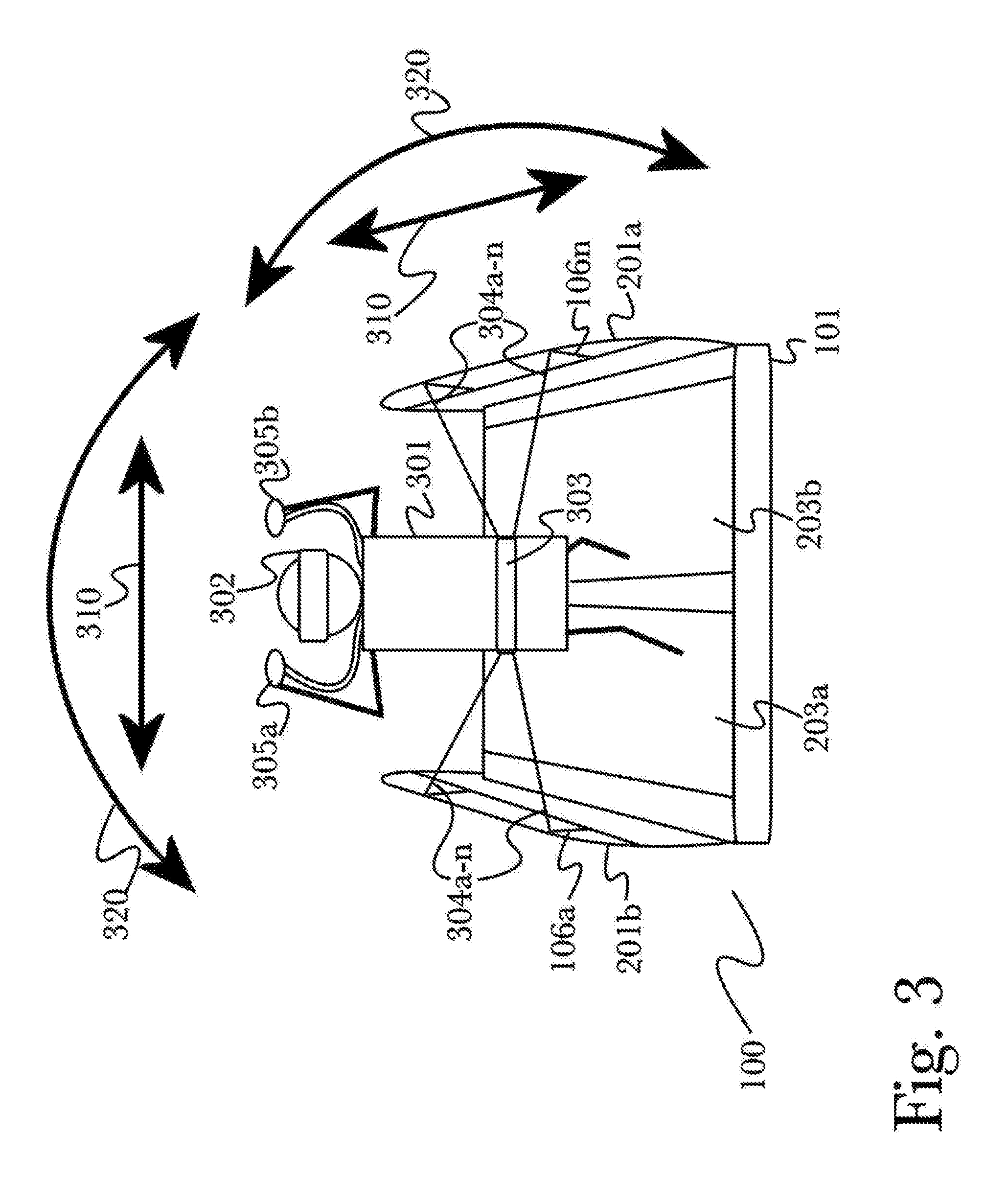
[0046] FIG. 1 is a side view of a variable-resistance exercise machine with wireless communication for smart device control and interactive software applications 100, according to an embodiment of the invention. According to the embodiment, an exercise machine 100 may have a stable base 101 to provide a platform for a user to safely stand or move about upon. Additional safety may be provided through the use of a plurality of integrally-formed or detachable side rails 102, for example having safety rails on the left and right sides (with respect to a user's point of view) of exercise machine 100 to provide a stable surface for a user to grasp as needed. Additionally, side rails 102 may comprise a plurality of open regions 105a-n formed to provide additional locations for a user to grasp or for the attachment of additional equipment such as a user's smart device (not shown) through the use of a mountable or clamping case or mount. Formed or removable supports 106a-n may be used for additional grip or mounting locations, for example to affix a plurality of tethers (not shown) for use in interaction with software applications while a user is using exercise machine 100 (as described below, referring to FIG. 3).
[0047] Exercise machine 100 may further comprise a rigid handlebar 103 affixed or integrally-formed on one end of exercise machine 100, for a user to hold onto while facing forward during use. Handlebar 103 may further comprise a stand or mount 104 for a user's smart device such as (for example) a smartphone or tablet computer, so they may safely support and stow the device during use while keeping it readily accessible for interaction (for example, to configure or interact with a software application they are using, or to select different applications, or to control media playback during use, or other various uses). Handlebar 103 may be used to provide a stable handle for a user to hold onto during use for safety or stability, as well as providing a rigid point for the user to "push off" during use as needed, for example to begin using a moving treadmill surface (described below in FIG. 2). During use, a user may also face away from handlebar 103, using exercise machine 100 in the reverse without their view or range of motion being obscured or obstructed by handlebar 103 (for example, for use with a virtual reality game that requires a wide degree of movement from the user's hands for interaction).
[0048] As illustrated, the base 101 of exercise machine 100 may be formed with a mild, symmetrical curvature, to better approximate the natural range of movement of a user's body during use. Common exercise machines such as treadmills generally employ a flat surface, which can be uncomfortably during prolonged or vigorous use, and may cause complications with multi-directional movement or interaction while a user's view is obscured, as with a headset (described below in FIG. 3). By incorporating a gradual curvature, a user's movements may feel more natural and require less reorientation or accommodation to become fluid and proficient, and stress to the body may be reduced.
[0049] FIG. 3 is a diagram illustrating an exemplary system for a virtual reality or mixed reality enhanced exercise machine 100 with wireless communication for smart device control and interactive software applications using a smart device, illustrating the use of a plurality of connected smart devices and tethers, and showing interaction via the user's body as a control stick. According to the embodiment, a user 301 may be standing, walking, or running on a variable-resistance exercise machine 100 with wireless communication for smart device control and virtual reality applications with a stable base 101 and two separate moveable surfaces 203a, 203b for separate movement of the user's legs. Exercise machine 100 may have fixed handlebars with affixed or integrally-formed controllers 305a, 305b for use as connected smart devices for interaction, and support rails 201a, 201b for a user to hold onto or affix tethers for safety or interaction when needed. User 301 may interact with software applications using a variety of means, including manual interaction via controller devices 305a, 305b that may be held in the hand for example to use as motion-input control devices or (as illustrated) may be affixed or integrally-formed into exercise machine 100. This may provide a user with traditional means of interacting with software applications while using exercise machine 100. Additionally, a user's body position or movement may be tracked and used as input, for example via a plurality of tethers 304a-n affixed to handlebars 201a, 201b and a belt, harness or saddle 303 worn by user 301, or using a headset device 302 that may track the position or movement of a user's head as well as provide video (and optionally audio) output to the user, such as a virtual reality headset that displays images while blocking the user's view of the outside world, or an augmented reality or mixed reality headset that combines presented information with the user's view using transparent or semitransparent displays (for example, using transparent OLED displays, hologram displays, projected displays, or other various forms of overlaying a display within a user's normal field of vision without obstructing the user's view). Body tracking may be used to recognize additional input data from user 301 (in addition to manual input via controllers 305a, 305b), by tracking the position and movement of user 301 during use. For example, motion tracking within a headset device 302 may be used to recognize a variety of translational 310 or rotational 320 movement of user's 301 head, such as leaning to the side, or looking over the shoulder. Tethers 304a-n may recognize a variety of movement of user's 301 torso, such as leaning, crouching, sidestepping, or other body movement. This body tracking may then be utilized either as feedback to rehab programs (for example, to track a user's posture for physical therapy coaching or exercises such as holding yoga poses) or input similar to a control stick or joystick in manual controller arrangements, for example by interpreting the user's entire body as the "stick" and processing their body movements as if they were stick movements done manually (such as to control in-game character posture or movement, or to direct movement in certain applications such as vehicle simulations that may turn or accelerate in response to stick movements).
[0050] For example, a user 301 on exercise machine 100 may be playing a virtual reality skiing game or rehab program wherein they are given audio and video output via a headset 302 to immerse them in a virtual ski resort. When user 301 is not skiing, they may be able to use manual controls 305a, 305b for such operations as selecting from an on-screen menu, or typing text input such as to input their name or to chat with other players using text. When they begin skiing within the game, user 301 may be instructed in proper ski posture or technique, and may then use their body to control various aspects of their virtual skiing, such as leaning to the side 320 to alter their course and avoid trees or other skiers, or jumping 310 to clear rocks or gaps.
[0051] Movement of their head may be detected by a headset 302 and used to control their view independently of their body as it is tracked by tethers 304a-n, allowing user 301 to look around freely without interfering with their other controls. In this manner, the user's entire body may serve as an input control device for the game, allowing and encouraging them to use natural body movements to control their gameplay in an immersive manner while still retaining the option to use more familiar manual control means as needed. Alternatively, specific body functions such as hip twisting are used as user feedback for rehabilitating programs, including rehab games.
[0052] FIG. 12 is a diagram illustrating an exemplary system 1200 for a virtual reality or mixed reality enhanced exercise machine 100, illustrating the use of a plurality of optical sensors to detect body movement of a user during use of an exercise machine. As above (with reference to FIG. 3), a user 301 may be standing, walking or running, sitting, or otherwise physically active during use of an exercise machine 100. During use, the user's position, posture, movement, cadence, technique, or any other movement or position-related information may be detected, observed, or measured using a plurality of body movement sensors such as (for example, including but not limited to) tethers 304a-n that may optionally be affixed to handlebars 201a-b or other features of an exercise machine 100, hardware sensors integrated into controllers 305a-b or a headset 302 the user may be using during exercise for virtual reality or mixed reality applications, or using a plurality of optical sensors 1201a-n that may be affixed to an exercise machine 100 or adjacent equipment, or that may be affixed to or positioned within an environment around exercise machine 100 to observe the user 301 during use. Optical sensors 1201a-n may be used in a variety of configurations or arrangements, such as using a single wide-angle sensor positioned to observe a user's movement or posture from a particular angle (which may be useful for coaching or physical therapy applications), or using more than one sensor placed about a user to observe their movement in three-dimensional space. A variety of hardware may be utilized in optical sensors 1201a-n, for example including (but not limited to) an infrared or other optical camera that may directly observe the user's movement, a structured-light emitter that projects a structured-light grid 1202 or other arrangement onto the user, exercise machine, or environment (and corresponding scanner or receiver that may observe the user's movement through detected changes in the structured-light projection), or a light-field sensor that detects or measures depth to observe a user's movement in three-dimensions. It should also be appreciated that various combination of optical sensors 1201a-n may be utilized to achieve a desired effect, for example using both structured light and a light-field sensor to observe a user's movement in precise detail in three dimensions. Additionally, some or all optical sensors 1201a-n utilized in some arrangements may be integrated into a user's headset 302 or an exercise machine 100 to provide "inside-out" tracking where tracking sensors are associated with the user rather than the environment, or they may be external devices as illustrated that may be introduced to enhance an existing exercise machine or environment.
[0053] Utilizing an exercise machine 100 in this manner allows for a variety of novel forms of user interaction within virtual reality or mixed reality applications. For example, a user's body movement during exercise may be tracked in three dimensions and along or around various axes to record movement with six degrees of freedom (6DOF) comprising both translation along, and rotation about, each of three spatial axes. This may be used with torso tracking as described above (referring to FIGS. 3-7) to produce a 6DOF "torso joystick" virtual device that directs movement or other inputs within a software application. This may be used in a number of ways, for example including but not limited to aiding exercise through interactive coaching (either with a human coach or using software to simulate a coach by providing feedback to detected user movements), providing physical therapy, interacting with games or other applications during exercise, or using exercise combined with software interaction for an immersive virtual reality or mixed reality experience. For example, a user may control movement or expression of a virtual avatar or other user representation within a software application, such as using their own body movements to direct movement of a virtual character. Physical therapy or fitness coaching may utilize detected movements to assist a user with improving their abilities or technique, or to measure progress. Social interaction applications may utilize body movements during exercise, for example a chat or voice call application may utilize body movement as a form of nonverbal expression similar to emoji or other icons. Safety may also be enhanced by controlling the operation of software in response to detected user movements, for example displaying caution information or pausing an application if a user is detected to move outside a configured safety parameter (such as stepping off a running treadmill, for example).
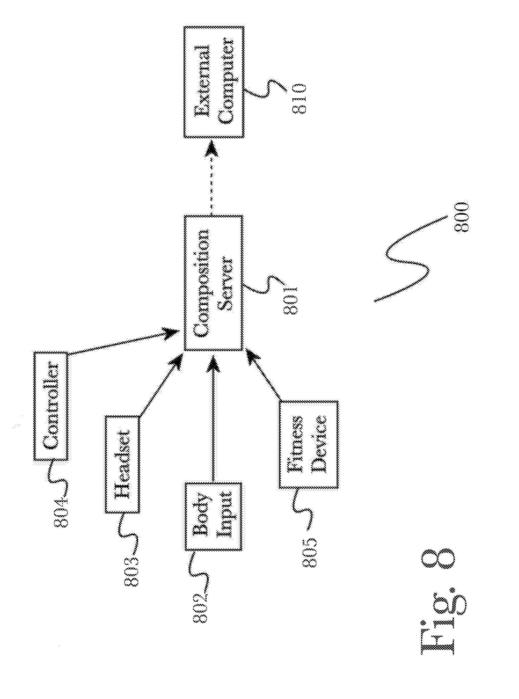
[0054] FIG. 8 is a block diagram of an exemplary system architecture 800 for natural body interaction for mixed or virtual reality applications, according to an embodiment of the invention. According to the embodiment, a composition server 801 comprising programming instructions stored in a memory 11 and operating on a processor 12 of a computing device 10 (as described below, with reference to FIG. 13), may be configured to receive a plurality of input data from various connected devices. Such input devices may include (but are not limited to) a variety of hardware controller devices 804 (such as a gaming controller [such as GOJI PLAY.TM. controllers], motion tracking controller, or traditional computer input devices such as a keyboard or mouse), a headset device 803 such as an augmented reality or mixed or virtual reality headset (for example, OCULUS RIFT.TM., HTC VIVE.TM., SAMSUNG GEAR VR.TM., MICROSOFT MIXED REALITY.TM., or other headset devices), a variety of fitness devices 805 (for example, fitness tracking wearable devices such as FITBIT.TM., MICROSOFT BAND.TM., APPLE WATCH.TM., or other wearable devices), or a variety of body input 802 tracking devices or arrangements, such as using a plurality of tethers attached to the environment and a harness worn by a user, configured to track movement and position of the user's body.
[0055] Various input devices may be connected to composition server 801 interchangeably as desired for a particular arrangement or use case, for example a user may wish to use a controller 804 in each hand and a headset 803, but omit the use of fitness devices 805 altogether. During operation, composition server 801 may identify connected devices and load any stored configuration corresponding to a particular device or device type, for example using preconfigured parameters for use as a default configuration for a new controller, or using historical configuration for a headset based on previous configuration or use. For example, a user may be prompted (or may volunteer) to provide configuration data for a particular device, such as by selecting from a list of options (for example, "choose which type of device this is", or "where are you wearing/holding this device", or other multiple-choice type selection), or composition server 801 may employ machine learning to automatically determine or update device configuration as needed. For example, during use, input values may be received that are determined to be "out of bounds", for example an erroneous sensor reading that might indicate that a user has dramatically shifted position in a way that should be impossible (for example, an erroneous reading that appears to indicate the user has moved across the room and back again within a fraction of a second, or has fallen through the floor, or other data anomalies). These data values may be discarded, and configuration updated to reduce the frequency of such errors in the future, increasing the reliability of input data through use.
[0056] Composition server 801 may receive a wide variety of input data from various connected devices, and by comparing against configuration data may discard undesirable or erroneous readings as well as analyze received input data to determine more complex or fine-grained measurements. For example, combining input from motion-sensing controllers 804 with a motion-sensing headset 803 may reveal information about how a user is moving their arms relative to their head or face, such as covering their face to shield against a bright light or an attack (within a game, for example), which might otherwise be impossible to determine with any reliability using only the controllers themselves (as it may be observed that a user is raising their hands easily enough, but there is no reference for the position or movement of their head). These derived input values may then be combined into a single composite input data stream for use by various software applications, such as augmented reality or mixed or virtual reality productivity applications (for example, applications that assist a user in performing manual tasks by presenting virtual information overlays onto their field of vision, or by playing audio directions to instruct them while observing their behavior through input devices, or other such applications), or mixed or virtual reality applications or games, such as simulation games that translate a user's movement or position into in-game interaction, for example by moving a user's in-game character or avatar based on their physical movements as received from input devices. In some arrangements, composition server 801 may operate such software applications in a standalone manner, functioning as a computer or gaming console as needed. In other arrangements, composition server 801 may provide the composite data for use by an external computer 810, such as a connected gaming console, mixed or virtual reality device, personal computer, or a server operating via a network in the cloud (such as for online gaming arrangements, for example). In this manner, the composite data functions of the embodiment may be utilized with existing hardware if desired, or may be provided in a standalone package such as for demonstrations or public use, or for convenient setup using a single device to provide the full interaction experience (in a manner similar to a household gaming console, wherein all the functions of computer components may be prepackaged and setup to minimize difficulty for a new user).
[0057] It should be appreciated that while reference is made to virtual reality applications, a wide variety of use cases may be possible according to the embodiment. For example, torso tracking may be used for fitness and health applications, to monitor a user's posture or gait while walking, without the use of additional virtual reality equipment or software. In some arrangements, some or all interaction between a user and a software application may be nonvisual, and in some arrangements no display device may be present. In such an arrangement, a user may interact with software entirely using feedback and movement of a worn harness 420 or tethers 304a-n, using resistance or software-guided actuation of tethers 304a-n (as described below, with reference to FIGS. 4-7) or other elements. In other arrangements, various combinations of display devices and other electronic devices may be used for a mixed-reality setup, for example where a user's movement and interaction may be used by software to incorporate elements of the physical world into a digital representation of the user or environment. For example, a user may interact with games or fitness applications, participate in social media such as chat, calls, online discussion boards, social network postings, or other social content, or they may use body tracking to navigate user interface elements of software such as a web browser or media player. Software used in this manner may not need to be specially-configured to utilize body tracking, for example to navigate a web browser a user's body movements or reactions to feedback may be processed by a composition server 801 and mapped to generic inputs such as keystrokes or mouse clicks, for use in any standard software application without the need for special configuration.
[0058] It should be further appreciated that while reference is made to a treadmill-type exercise machine 100, such an exercise machine is exemplary and any of a number of exercise machines may be utilized according to the aspects disclosed herein, for example including (but not limited to) a treadmill, a stationary bicycle, an elliptical machine, a rowing machine, or even non-electronic exercise equipment such as a pull-up bar or weight machine. Traditional exercise equipment may be outfitted with additional components to facilitate virtual reality or mixed reality interaction according to the aspects disclosed herein, for example by affixing a plurality of tethers 304a-n to a weight machine so that a user's movement during exercise may be used as interaction as described below (with reference to FIGS. 3-7).
DETAILED DESCRIPTION OF EXEMPLARY EMBODIMENTS
[0059] FIG. 2 is a top-down view of a variable-resistance exercise machine 100 with wireless communication for smart device control and interactive software applications, according to an embodiment of the invention. According to the embodiment, exercise machine 100 may comprise a stable base 101 to provide a platform for a user to safely stand or move about upon. Exercise machine 100 may further comprise right 201a and left 201b hand rails for a user to brace against or grip during use, to provide a stable support for safety as well as a mounting point for external devices such as a plurality of tethers, as described below with reference to FIG. 3. A plurality of steps 202a-n may be used to provide a user with a safe and easy means to approach or dismount exercise machine 100, as well as a nonmoving "staging area" where a user may stand while they configure operation or wait for exercise machine 100 to start operation. Unlike traditional treadmill machines common in the art, exercise machine 100 may be made with greater width to accommodate a wider range of free movement of a user's entire body (whereas traditional treadmills are designed to best accommodate only a jogging or running posture, with minimal lateral motion), and a plurality of separate moving surfaces 203a-b may be utilized to provide multiple separate surfaces that may move and be controlled independently of one another during use. For example, a user may move each of their legs independently without resistance applied, with separate moving surfaces 203a-b moving freely underfoot as a user applies pressure during their movement. This may provide the illusion of movement to a user while in reality they remain stationary with respect to their surroundings. Another use may be multiple separate moving surfaces 203a-b, with separate speeds of movement or degrees of resistance, so that as a user moves about during use they may experience physical feedback in the form of changing speed or resistance, indicating where they are standing or in what direction they are moving (for example, to orient a user wearing a virtual reality headset, as described below with reference to FIG. 3). Moving surfaces 203a-b may be formed with a texture 204 to increase traction, which may improve user safety and stability during use as well as improve the operation of moving surfaces 203a-b for use in multidirectional movement (as the user's foot is less likely to slide across a surface rather than taking purchase and applying directional pressure to produce movement). Use of multiple, multidirectional moving surfaces 203a-b may also be used in various therapeutic or rehabilitation roles, for example to aid a user in developing balance or range of motion. For example, a user who is recovering from an injury or surgery (such as a joint repair or replacement surgery) may require regular physical therapy during recovery. Use of multidirectional moving surfaces 203a-b along with appropriate guidance from a rehabilitation specialist or physical therapist (or optionally a virtual or remote coach using a software application) may make regular therapy more convenient and accessible to the user, rather than requiring in-home care or regular visits to a clinic. For example, by enabling a therapist or coach to manually vary the movement and resistance of the moving surfaces 203a-b, they can examine a user's ability to overcome resistance to different movements such as at odd angles or across varying range of motion, to examine the user's physical health or ability. By further varying the resistance it becomes possible to assist the user with rehabilitation by providing targeted resistance training to specific movements, positions, or muscle groups to assist in recovery and development of the user's abilities.
[0060] Exercise machine 100 may be designed without a control interface commonly utilized by exercise machines in the art, instead being configured with any of a variety of wireless network interfaces such as Wi-Fi or BLUETOOTH.TM. for connection to a user's smart device, such as a smartphone or tablet computer. When connected, a user may use a software application on their device to configure or direct the operation of exercise machine 100, for example by manually configuring a variety of operation settings such as speed or resistance, or by interacting with a software application that automatically directs the operation of exercise machine 100 without exposing the particular details of operation to a user. Additionally, communication may be bi-directional, with a smart device directing the operation of exercise machine 100 and with exercise machine 100 providing input to a smart device based at least in part on a user's activity or interaction. For example, a user may interact with a game on their smart device, which directs the operation of exercise machine 100 during play as a form of interaction with, and feedback to, the user. For example, in a racing game, exercise machine 100 may alter the resistance of moving surfaces 203a-b as a user's speed changes within the game. In another example, a user may be moving about on moving surfaces 203a-b while playing a simulation or roleplaying game, and their movement may be provided to the connected smart device for use in controlling an in-game character's movement. Another example may be two-way interactive media control, wherein a user may select media such as music for listening on their smart device, and then while using exercise machine 100 their level of exertion (for example, the speed at which they run or jog) may be used to provide input to their smart device for controlling the playback of media. For example, if the user slows down music may be played slowly, distorting the audio unless the user increases their pace. In this manner, exercise machine 100 may be used interchangeably as a control and feedback device or both simultaneously, providing an immersive environment for a wide variety of software applications such as virtual reality, video games, fitness and health applications, or interactive media consumption.
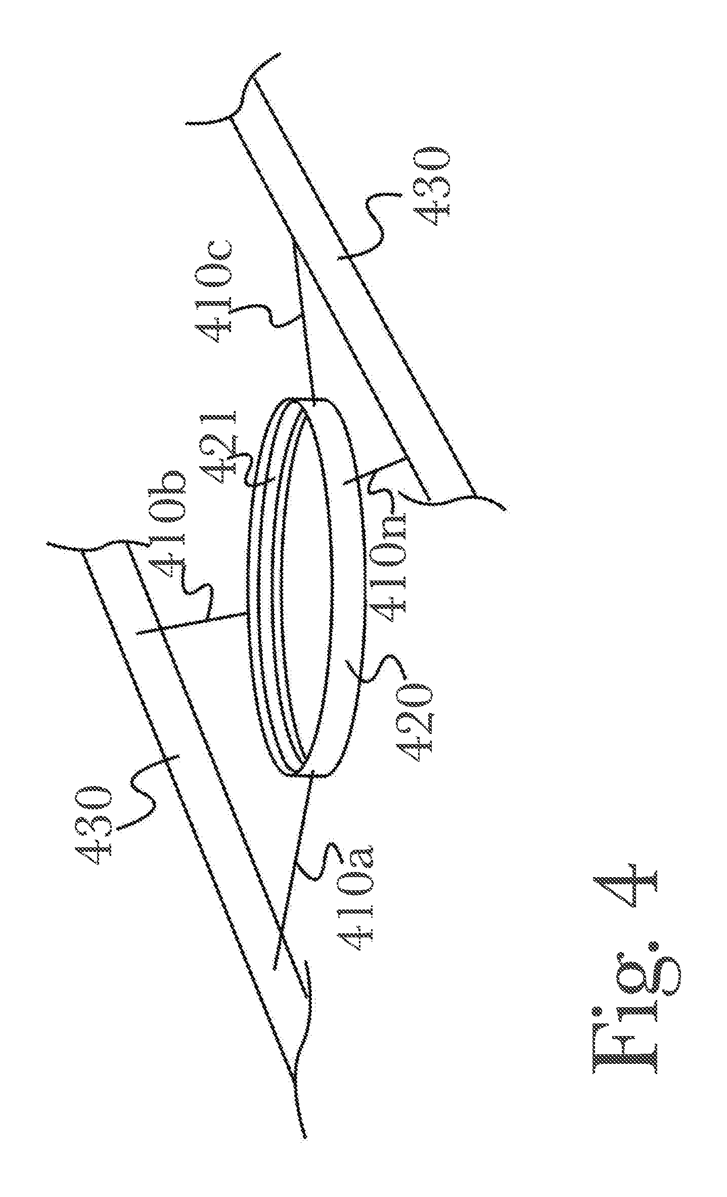
[0061] FIG. 4 is a diagram of an exemplary hardware arrangement 400 for natural torso tracking and feedback for electronic interaction according to an embodiment of the invention, illustrating the use of multiple tethers 410a-n and a movable torso harness 420. According to the embodiment, a plurality of tethers 410a-n may be affixed or integrally-formed as part of a handle or railing 430, such as handlebars found on exercise equipment such as a treadmill, elliptical trainer, stair-climbing machine, or the like. In alternate arrangements, specifically-designed equipment with integral tethers 410a-n may be used, but it may be appreciated that a modular design with tethers 410a-n that may be affixed and removed freely may be desirable for facilitating use with a variety of fitness equipment or structural elements of a building, according to a user's particular use case or circumstance. Tethers 410a-n may then be affixed or integrally-formed to a torso harness 420, as illustrated in the form of a belt, that may be worn by a user such that movement of their body affects tethers 410a-n and applies stress to them in a variety of manners. It should be appreciated that while a belt design for a torso harness 420 is shown for clarity, a variety of physical arrangements may be used such as including (but not limited to) a vest, a series of harness-like straps similar to climbing or rappelling equipment, a backpack, straps designed to be worn on a user's body underneath or in place of clothing (for example, for use in medical settings for collecting precise data) or a plurality of specially-formed clips or attachment points that may be readily affixed to a user's clothing. Additionally, a torso harness 420 may be constructed with movable parts, for example having an inner belt 421 that permits a user some degree of motion within the harness 420 without restricting their movement. Movement of inner belt 421 (or other movable portions) may be measured in a variety of ways, such as using accelerometers, gyroscopes, or optical sensors, and this data may be used as interaction with software applications in addition to data collected from tethers 410a-n as described below. In some embodiments, a saddle-like surface on which a user may sit may be used, with motion of the saddle-like surface measured as described generally herein.
[0062] As a user moves, his or her body naturally shifts position and orientation. These shifts may be detected and measured via tethers 410a-n, for example by detecting patterns of tension or strain on tethers 410a-n to indicate body orientation, or by measuring small changes in strain on tethers 410a-n to determine more precise movements such as body posture while a user is speaking, or specific characteristics of a user's stride or gait. Additionally, through varying the quantity and arrangement of tethers 410a-n, more precise or specialized forms of movement may be detected and measured (such as, for example, using a specific arrangement of multiple tethers connected to a particular area of a user's body to detect extremely small movements for medical diagnosis or fitness coaching). This data may be used as interaction with software applications, such as for virtual reality applications as input for a user to control a character in a game. In such an arrangement, when a user moves, this movement may be translated to an in-game character or avatar to convey a more natural sense of interaction and presence. For example, in a multiplayer roleplaying game, this may be used to facilitate nonverbal communication and recognition between players, as their distinct mannerisms and gestures may be conveyed in the game through detection of natural torso position and movement. In fitness or health applications, this data may be used to track and monitor a user's posture or ergonomic qualities, or to assist in coaching them for specific fitness activities such as holding a pose for yoga, stretching, or proper running form during use with a treadmill. In medical applications, this data may be used to assist in diagnosing injuries or deficiencies that may require attention, such as by detecting anomalies in movement or physiological adaptations to an unrecognized injury (such as when a user subconsciously shifts their weight off an injured foot or knee, without consciously realizing an issue is present).
[0063] Through various arrangements of tethers 410a-n and tether sensors (as described below, referring to FIGS. 5-7), it may be possible to enable a variety of immersive ways for a user to interact with software applications, as well as to receive haptic feedback from applications. For example, by detecting rotation, tension, stress, or angle of tethers a user may interact with applications such as virtual reality games or simulations, by using natural body movements and positioning such as leaning, jumping, crouching, kneeling, turning, or shifting their weight in various directions to trigger actions within a software application configured to accept torso tracking input. By applying haptic feedback of varying form and intensity (as is described in greater detail below, referring to FIG. 5), applications may provide physical indication to a user of software events, such as applying tension to resist movement, pulling or tugging on a tether to move or "jerk" a user in a direction, or varying feedback to multiple tethers such as tugging and releasing in varying order or sequence to simulate more complex effects such as (for example, in a gaming use case) explosions, riding in a vehicle, or walking through foliage.
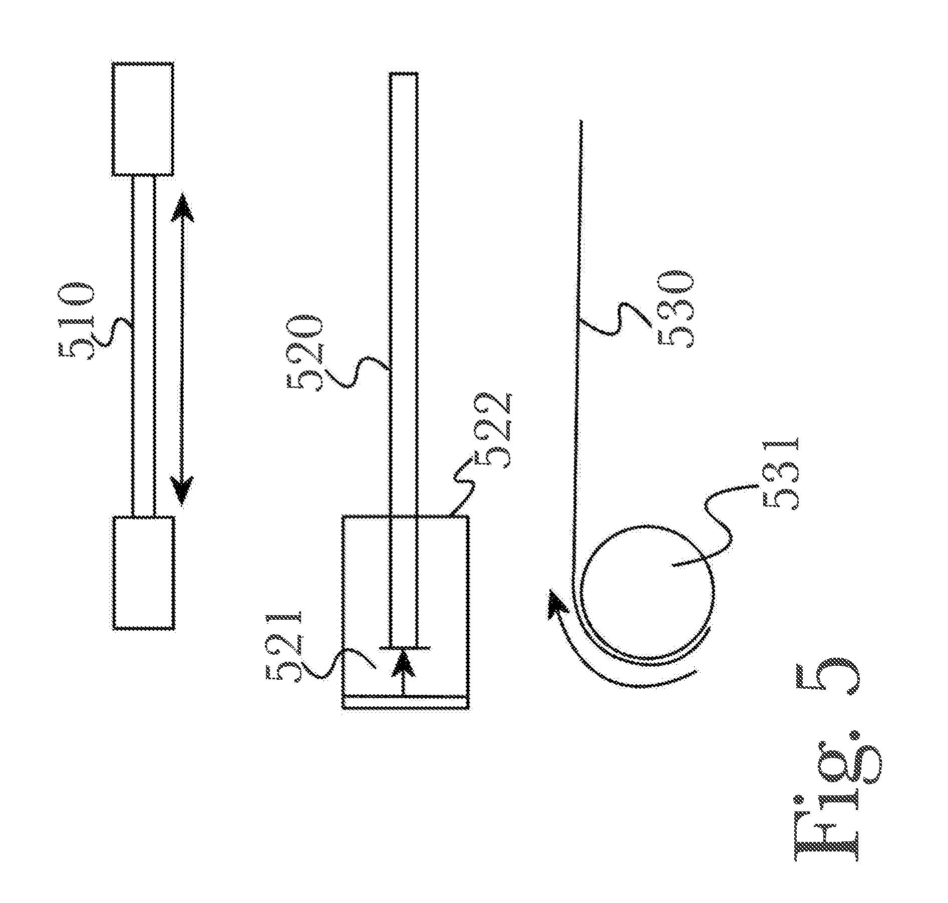
[0064] FIG. 5 is a diagram illustrating a variety of alternate tether arrangements. According to various use cases and hardware arrangements, tethers 410a-n may utilize a variety of purpose-driven designs as illustrated. For example, a "stretchable" tether 510 may be used to measure strain during a user's movement, as the tether 510 is stretched or compressed (for example, using piezoelectric materials and measuring electrical changes). Such an arrangement may be suitable for precise measurements, but may lack the mechanical strength or durability for gross movement detection or prolonged use. An alternate construction may utilize a non-deforming tether 520 such as a steel cable or similar non-stretching material. Instead of measuring strain on the tether 520, instead tether 520 may be permitted a degree of movement within an enclosure 522 (for example, an attachment point on a torso harness 420 or handlebar 430), and the position or movement 521 of the tether 520 may be measured such as via optical sensors. In a third exemplary arrangement, a tether 530 may be wound about an axle or pulley 531, and may be let out when force is applied during a user's movement. Rotation of the pulley 531 may be measured, or alternately a tension device such as a coil spring may be utilized (not shown) and the tension or strain on that device may be measured as tether 530 is extended or retracted. In this manner, it may be appreciated that a variety of mechanical means may be used to facilitate tethers and attachments for use in detecting and measuring natural torso position and movement, and it should be appreciated that a variety of additional or alternate hardware arrangements may be utilized according to the embodiments disclosed herein.
[0065] Additionally, through the use of various hardware construction it becomes possible to utilize both "passive" tethers that merely measure movement or strain, as well as "active" tethers that may apply resistance or movement to provide haptic feedback to a user. For example, in an arrangement utilizing a coiled spring or pulley 531, the spring or pulley 531 may be wound to retract a tether and direct or impede a user's movement as desired. In this manner, various new forms of feedback-based interaction become possible, and in virtual reality use cases user engagement and immersion are increased through more natural physical feedback during their interaction.
[0066] By applying various forms and intensities of feedback using various tether arrangements, a variety of feedback types may be used to provide haptic output to a user in response to software events. For example, tension on a tether may be used to simulate restrained movement such as wading through water or dense foliage, walking up an inclined surface, magnetic or gravitational forces, or other forms of physical resistance or impedance that may be simulated through directional or non-directional tension. Tugging, retracting, or pulling on a tether may be used to simulate sudden forces such as recoil from gunfire, explosions, being grabbed or struck by a software entity such as an object or character, deploying a parachute, bungee jumping, sliding or falling, or other momentary forces or events that may be conveyed with a tugging or pulling sensation. By utilizing various patterns of haptic feedback, more complex events may be communicated to a user, such as riding on horseback or in a vehicle, standing on the deck of a ship at sea, turbulence in an aircraft, weather, or other virtual events that may be represented using haptic feedback. In this manner, virtual environments and events may be made more immersive and tangible for a user, both by enabling a user to interact using natural body movements and positioning, as well as by providing haptic feedback in a manner that feels natural and expected to the user. For example, if a user is controlling a character in a gaming application through a first-person viewpoint, it would seem natural that when their character is struck there would be a physical sensation corresponding to the event; however, this is not possible with traditional interaction devices, detracting from any sense of immersion or realism for the user. By providing this physical sensation alongside the virtual event, the experience becomes more engaging and users are encouraged to interact more naturally as their actions results in natural and believable feedback, meeting their subconscious expectations and avoiding excessive "immersion-breaking" moments, which in turn reduces the likelihood of users adopting unusual behaviors or unhealthy posture as a result of adapting to limited interaction schema.
[0067] Haptic feedback may be provided to notify a user of non-gaming events, such as for desktop notifications for email or application updates, or to provide feedback on their posture for use in fitness or health coaching. For example, a user may be encouraged to maintain a particular stance, pose, or posture while working or for a set length of time (for example, for a yoga exercise application), and if their posture deviates from an acceptable range, feedback is provided to remind them to adjust their posture. This may be used in sports, fitness, health, or ergonomic applications that need not utilize other aspects of virtual reality and may operate as traditional software applications on nonspecialized computing hardware. For example, a user at their desk may use an ergonomic training application that monitors their body posture throughout the work day and provides haptic reminders to correct poor posture as it is detected, helping the user to maintain a healthy working posture to reduce fatigue or injuries due to poor posture (for example, repetitive-stress injuries that may be linked to poor posture while working at a computer).
[0068] FIG. 6 is a diagram of an additional exemplary hardware arrangement 600 for natural torso tracking and feedback for electronic interaction according to an embodiment of the invention, illustrating the use of angle sensors 612, 621a-n to detect angled movement of a tether 620. According to one exemplary arrangement, a tether 610 may be affixed to or passed through a rotating joint such as a ball bearing 611 or similar, to permit free angular movement. During movement, the angular movement or deflection 612 of a protruding bar, rod, or tether segment 613 may be measured (for example, using optical, magnetic, or other sensors) to determine the corresponding angle of tether 610. In this manner, precise angle measurements may be collected without impeding range of motion or introducing unnecessary mechanical complexity.
[0069] In an alternate hardware arrangement, the use of angle sensors 621a-n enables tracking of a vertical angle of a tether 620, to detect and optionally measure vertical movement or orientation of a user's torso. When tether 620 contacts a sensor 621a-n, this may be registered and used to detect a general vertical movement (that is, whether the tether is angled up or down). For more precise measurements, the specific hardware construction of a sensor 621a-n may be varied, for example using a pressure-sensing switch to detect how much force is applied and use this measurement to determine the corresponding angle (as may be possible given a tether 620 of known construction). It should be appreciated that various combinations of hardware may be used to provide a desired method or degree of angle detection or measurement, for example using a conductive tether 620 and a capacitive sensor 621a-n to detect contact, or using a mechanical or rubber-dome switch (as are commonly used in keyboard construction) to detect physical contact without a conductive tether 620.
[0070] The use of angle detection or measurement may expand interaction possibilities to encompass more detailed and natural movements of a user's body. For example, if a user crouches, then all tethers 410a-n may detect a downward angle simultaneously. Additionally, data precision or availability may be enhanced by combining input from multiple available sensors when possible (for example, utilizing adaptive software to collect data from any sensors that it detects, without requiring specific sensor types for operation), for example by combining data from tethers 410a-n and hardware sensors such as an accelerometer or gyroscope, enabling multiple methods of achieving similar or varied types or precision levels of position or movement detection. Similarly, when a user jumps then all tethers may detect an upward angle simultaneously. However, if a user leans in one direction, it may be appreciated that not all tethers 410a-n will detect the same angle. For example, tethers 410a-n in the direction the user is leaning may detect a downward angle, while those on the opposite side would detect an upward angle (due to the orientation of the user's torso and thus a worn torso harness 420). In this manner, more precise torso interaction may be facilitated through improved detection and recognition of orientation and movement. Additionally, it may be appreciated that sensors 621a-n may be utilized for other angle measurements, such as to detect horizontal angle. For example, if a user is wearing a non-rotating torso harness 420, when they twist their body a similar stress may be applied to all attached tethers 410a-n. Without angle detection the precise nature of this movement will be vague, but with horizontal angle detection it becomes possible to recognize that all tethers 410a-n are being strained in a similar direction (for example, in a clockwise pattern when viewed from above, as a user might view tethers 410a-n during use), and therefore interpret the interaction as a twisting motion (rather than, for example, a user squatting or kneeling, which might apply a similar stress to the tethers 410a-n but would have different angle measurements).
[0071] FIG. 7 is a diagram illustrating an exemplary hardware arrangement of an apparatus for natural torso tracking and feedback for electronic interaction according to an embodiment of the invention, illustrating the use of multiple tethers 410a-n and a movable torso harness 420 comprising a plurality of angle sensors 701a-n positioned within the movable torso harness 420. According to the embodiment, a plurality of tethers 410a-n may be affixed or integrally-formed as part of a handle or railing 430, such as handlebars found on exercise equipment such as a treadmill, elliptical trainer, stair-climbing machine, or the like. In alternate arrangements, specifically-designed equipment with affixed or integral tethers 410a-n may be used, but it may be appreciated that a modular design with tethers 410a-n that may be affixed and removed freely may be desirable for facilitating use with a variety of fitness equipment or structural elements of a building, according to a user's particular use case or circumstance as well as weight-holding strength of the tethers. Tethers 410a-n may then be affixed or integrally-formed to angle sensors 701a-n placed within or integrally-formed as a component of torso harness 420 (as illustrated in the form of a belt) that may be worn by a user such that movement of their body affects tethers 410a-n and applies detectable or measurable stress to tethers 410a-n and angular motion to angle sensors 701a-n. In this manner, it may be appreciated that angle sensors 701a-n may be utilized as integral or removable components of a torso harness 420, as an alternative arrangement to utilizing angle sensors 701a-n placed or formed within railings 430 or other equipment components connected to distal ends of tethers 410a-n (with respect to the user's torso). According to various embodiments, sensors may be placed optionally on a belt, vest, harness, or saddle-like surface or at attachment points on safety railings, or indeed both.
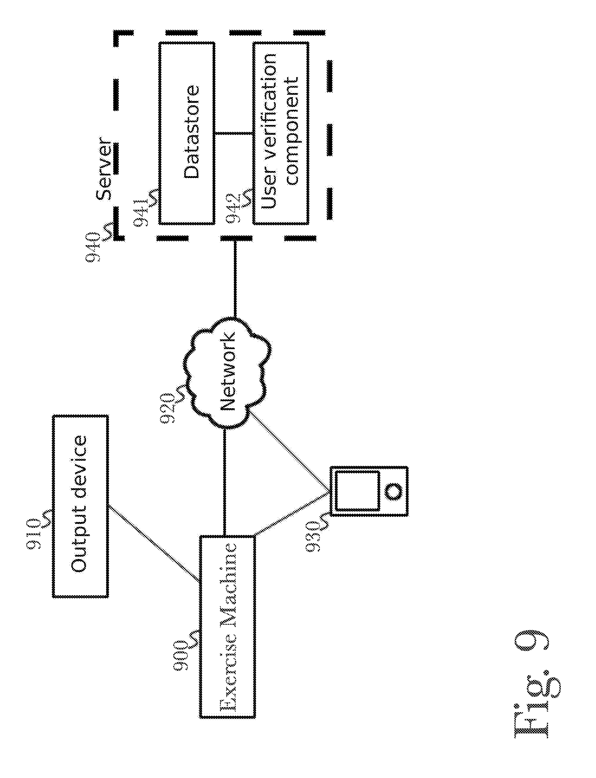
[0072] FIG. 9 is a block diagram of an exemplary system architecture of an exercise machine 900 being connected over local connections to a smartphone or computing device 930, an output device other than a phone 910, and a server 940 over a network 920, according to a preferred aspect. An exercise machine 100 may connect over a network 920, which may be the Internet, a local area connection, or some other network used for digital communication between devices, to a server 940. Such connection may allow for two-way communication between a server 940 and an exercise machine 800. An exercise machine 100 may also be connected over a network 920 to a smartphone or computing device 930, or may be connected directly to a smartphone or computing device 930 either physically or wirelessly such as with Bluetooth connections. An exercise machine 100 also may be connected to an output device 910 which may display graphical output from software executed on an exercise machine 100, including Mixed or virtual reality software, and this device may be different from a smartphone or computing device 930 or in some implementations may in fact be a smartphone or computing device 930. A remote server 940 may contain a data store 941, and a user verification component 942, which may contain typical components in the art used for verifying a user's identity from a phone connection or device connection, such as device ID from a smartphone or computing device or logging in with a user's social media account.
[0073] FIG. 10 is a diagram of an exemplary hardware arrangement of a smart phone or computing device 1030 executing software 1010 and communicating over a network 1020, according to a preferred aspect. In an exemplary smart phone or computing device 1030, key components include a wireless network interface 1031, which may allow connection to one or a variety of wireless networks including Wi-Fi and Bluetooth; a processor 1032, which is capable of communicating with other physical hardware components in the computing device 1030 and running instructions and software as needed; system memory 1033, which stores temporary instructions or data in volatile physical memory for recall by the system processor 1032 during software execution; and a display device 1034, such as a Liquid Crystal Display (LCD) screen or similar, with which a user may visually comprehend what the computing device 1030 is doing and how to interact with it. It may or may not be a touch enabled display, and there may be more components in a computing device 1030, beyond what are crucially necessary to operate such a device at all. Software 1010 operating on a processor 1033 may include a mixed or virtual reality application, a user verification system, or other software which may communicate with a network-enabled server 1040 and exercise machine 100 software for the purposes of enhanced mixed or virtual reality.
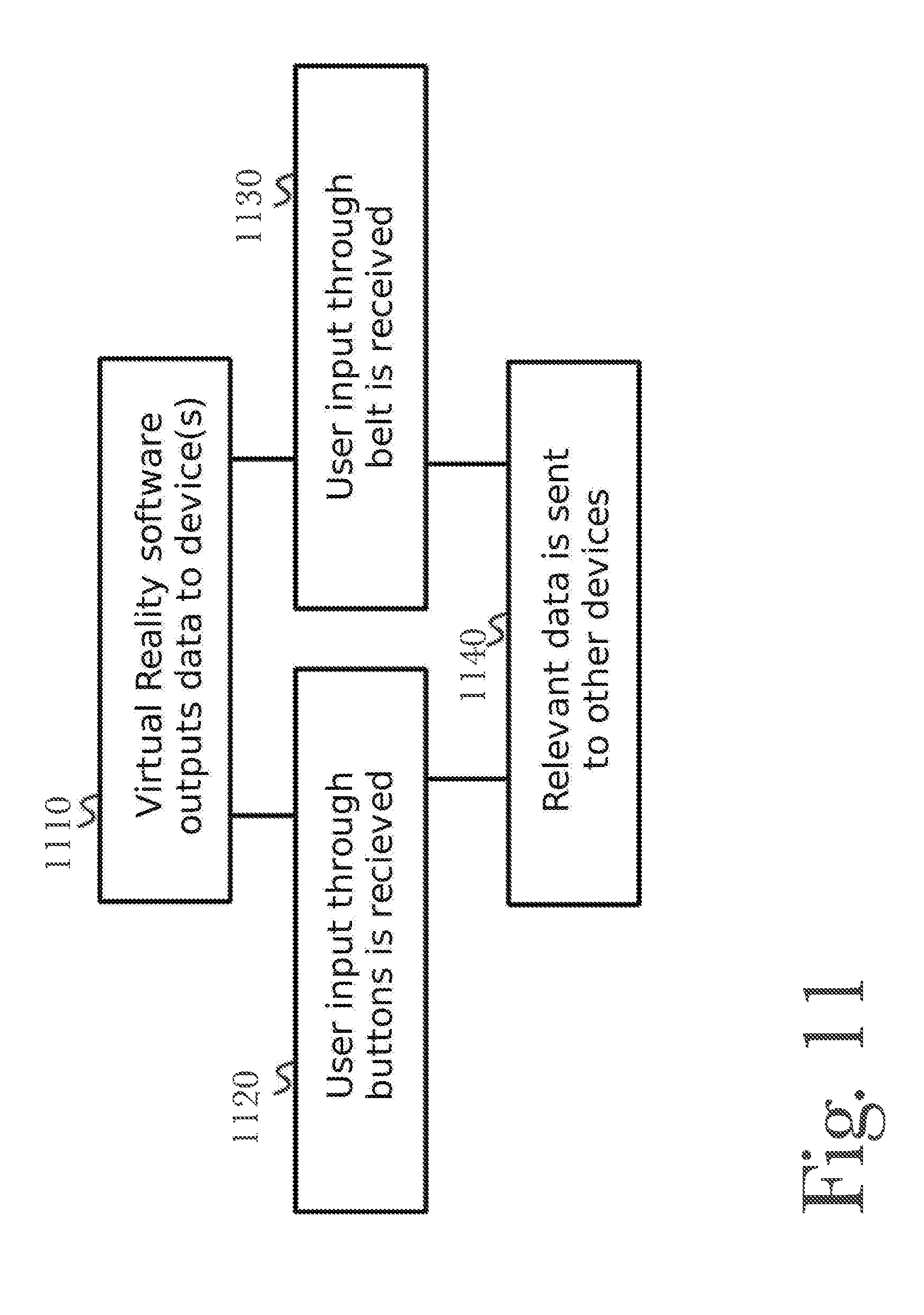
[0074] FIG. 11 is a block diagram of a method of mixed or virtual reality software operating to receive input through different sources, and send output to devices, according to a preferred aspect. Mixed or virtual reality software which may be run on a phone or computing device 1030 or another device, outputs data to a visual device for the purpose of graphically showing a user what they are doing in the software 1110. Such display may be a phone display 1034, or a separate display device such as a screen built into an exercise machine 100 or connected some other way to the system, or both display devices. During software execution, user input may be received either through buttons 1130 on the exercise machine 100, 1120, or through input from a belt-like harness 420, such as user orientation or movements. Such received data may be sent 1140 to either a mobile smart phone or computing device 1030, or to a server 1040 over a network 1020, or both, for processing, storage, or both. Data may be stored on a server with a data store device 1041 and may be processed for numerous uses including user verification with a user verification component 1042. Data may be processed either by software running on an exercise machine 100, a smart phone or computing device 1030, or some other connected device which may be running mixed or virtual reality software, when input is received from a user using either buttons on an exercise machine 100, a belt-like harness 420, or both, and optionally using hardware features of an exercise machine 100 such as handlebars, pedals, or other features in mixed or virtual reality software for tasks such as representing movement in a simulation.
[0075] FIG. 17 is a block diagram of an exemplary virtual reality or mixed reality enhanced exercise machine, illustrating the use of a stationary bicycle 1700 with hand controls on the handles 1720, and a belt-like harness attachment 420. A stationary exercise bicycle device 1700, which may be of any particular design including a reclining, sitting, or even unicycle-like design, possesses two pedals 1730 as is common for stationary exercise bicycles of all designs. On handlebars of a stationary exercise bicycle may exist buttons and controls 1720 for interacting with a virtual reality or mixed reality augmented piece of software, allowing a user to press buttons in addition to or instead of pedaling, to interact with the software. A belt-like harness attachment 420 is attached via a mechanical arm 1710 to a stationary exercise bicycle 1700, which may monitor motion and movements from a user during the execution of virtual reality software. A mechanical arm 1710 may have an outer shell composed of any material, the composition of which is not claimed, but must have hinges 1711, 1712, 1713 which allow for dynamic movement in any position a user may find themselves in, and angular sensors inside of the arm at the hinge-points 1711, 1712, 1713 for measuring the movement in the joints and therefore movement of the user. A stationary bicycle device 1700 may also have a pressure sensor in a seat 1740, the sensor itself being of no particularly novel design necessarily, to measure pressure from a user and placement of said pressure, to detect movements such as leaning or sitting lop-sided rather than sitting evenly on the seat.
[0076] FIG. 18 is a diagram of another exemplary virtual reality or mixed reality enhanced exercise machine 1800, illustrating the use of a treadmill exercise machine 100 a vest-type harness 1820 with a plurality of pistons 1811 to provide a hardware-based torso joystick with full-body tracking. According to this embodiment, a treadmill or other exercise machine 100 may comprise a plurality of rigid side rails 102 for a user to grip for support as needed during use (for example, as a balance aid or to assist getting on the machine and setting up other equipment properly) as well as a rigid stand or mount 104 for a user's smartphone or other computing device, that may be used to operate a virtual reality or mixed reality software application. Exercise machine 100 may further comprise a jointed arm 1810 or similar assembly that may be integrally-formed or removably affixed to or installed upon exercise machine 100. Arm 1810 may utilize a plurality of pistons 1811 to provide for movement during use in order to follow the movement's of a user's body, as well as to provide tension or resistance to motion when appropriate (for example, to resist a user's movements or to provide feedback) and motion detection of a user's movement during use, according to various aspects described previously (referring to FIGS. 3-7, for example) by measuring movement of a piston 1811 or arm 1810 and optionally applying tension or resistance to piston 1811 to retard movement of arm 1810 and constrain user movement or simulate specific forms of physical feedback. For example, if a user is moving an avatar in a virtual reality software application, when the avatar encounters an obstacle such as another avatar, object, or part of the environment, resistance may be applied to piston 1811 to prevent the user from moving further, so that their avatar is effectively prevented from moving through the obstacle and thereby facilitating the immersive experience of a solid object in a virtual environment. Additional arms may be used for a user's limbs 1821 and may incorporate straps 1822 to be affix about a user's arm, wrist, or other body part (for example, when placed through an appropriate arm or limb hole 1823 in vest harness 1820 while worn), to incorporate more detailed movement tracking of a user's arms and/or legs rather than just torso-based tracking. A vest-type harness 1820 may be affixed to jointed arm 1810 using a movable joint 1812 such as a ball joint (for example) and used in place of a belt 420, to allow for more natural movement or to provide greater area upon which to affix additional arms 1821, pistons 1811, or any of a variety of sensors, for example such as accelerometers or gyroscopes for detecting body orientation (not all optional sensors are shown for the sake of clarity). For example, a vest 1820 may have integrated feedback actuators for use in first-person software applications to simulate impacts or recoil, or it may incorporate heating or cooling elements to simulate different virtual environments while worn. Additionally, vest 1820 may incorporate electrical connectors 1824 for various peripheral devices such as controllers 305a-b or a headset 302, reducing the risk of tangles or injury by keeping cables short and close to the user so they cannot cause issues during movement or exercise.
[0077] FIG. 19 is a diagram of another exemplary virtual reality or mixed reality enhanced exercise machine, illustrating the use of a stationary bicycle 1900 with a vest-type harness 1820 with a plurality of strain sensors 1911 and tethers 1912, according to an aspect of the invention. According to this embodiment, rather than a jointed arm 1810 and pistons 1811, a solid flexible arm 1910 may be used to detect user movement while positioned on a seat 1902 to use exercise machine 100, for example while the user is seated to use pedals 1901 on a stationary bike or elliptical training machine. Through a plurality of strain gauges 1911 that detect the flexion or extension of the solid arm. Tethers 1912 may be used for either movement tracking or providing feedback to a user, or both, and may optionally be connected or routed through joints or interconnects 1913 to allow for a greater variety of attachment options as well more precise feedback (for example, by enabling multiple angles from which a tether 1912 may apply force, to precisely simulate different effects). Additional arms may be used for a user's limbs 1921 and may incorporate straps 1922 to be affix about a user's arm, wrist, or other body part, to incorporate more detailed movement tracking of a user's arms and/or legs rather than just torso-based tracking. Additional arms 1921 may also incorporate additional tethers 1912 and strain sensors 1911 to track movement and apply feedback to specific body parts during use, further increasing precision and user immersion. A vest-type harness 1820 may be used in place of a belt 420, to allow for more natural movement or to provide greater area upon which to affix additional arms 1921, tether 1912, or any of a variety of sensors, for example such as accelerometers or gyroscopes for detecting body orientation (not all optional sensors are shown for the sake of clarity). For example, a vest 1820 may have integrated feedback actuators for use in first-person software applications to simulate impacts or recoil, or it may incorporate heating or cooling elements to simulate different virtual environments while worn. Additionally, vest 1820 may incorporate electrical connectors 1914 for various peripheral devices such as controllers 305a-b or a headset 302, reducing the risk of tangles or injury by keeping cables short and close to the user so they cannot cause issues during movement or exercise.
[0078] FIG. 20 is a flow diagram illustrating an exemplary method 2000 for operating a virtual and mixed-reality enhanced exercise machine, according to one aspect. According to the aspect, a user may wear 2001 a torso harness such as a belt 420 or vest 1820 harness, while they engage in the use 2002 of an exercise machine 100. While using the exercise machine 100, the user's movements may be detected and measured 2003 through the use of a plurality of body movement sensors such as (for example, including but not limited to) strain sensors 1911, tethers 410a-c, 1912, pistons 1811, or optical sensors 1201a-n. These measured user movements may then be mapped by a composition server 801 to correspond to a plurality of movement inputs of a virtual joystick device 2004. These virtual joystick inputs may then be transmitted 2005 to a software application, for example a virtual reality or mixed reality application operating on a user device such as (for example, including but not limited to) a smartphone 930, personal computing device, or headset 302. Composition server 801 may then receive feedback from the software application 2006, and may direct the operation of a plurality of feedback devices such as tethers 410a-c, 1912 or pistons 1811 to resist or direct the user's movement 2007 to provide physical feedback to the user based on the received software feedback.
[0079] FIG. 21 is a diagram of another exemplary virtual reality or mixed reality enhanced exercise machine 2100, illustrating the use of a rotating platform, a waist belt 2110 and joints 2120a-c providing full range of motion. As shown in view 2, a virtual reality or mixed reality exercise machine 2100 may comprise an exercise machine such as (for example) a treadmill 2130 that has a movable or pivotable base 2132, for example via a turnstile 2131 or similar joint for allowing movement of the entire exercise machine 2100 while base 2132 remains stationary or fixed to the floor. A waist belt 2110 such as a padded hip belt or a support belt (such as those used for weight lifting or other physical activities, or those used for physical therapy or other medical uses) may be utilized with belt straps 2111 and buckle 2112 to fasten about a user's waist. Waist belt 2110 may be attached to exercise machine 2100 using a plurality of ball or similar joints 2120a-c configured to allow for full range of motion, enabling complex user movements and posture and allowing the use of full freedom of movement when interacting with software applications. A plurality of pistons 1811 or other means may be used, as described previously, to restrict or direct user movement or to provide feedback, enabling a variety of interaction and feedback options as well as providing a means to control and manipulate user movement both for immersion in virtual or mixed reality applications as well as for a variety of medical or therapeutic uses, such as preventing users from exceeding recommended range of motion during physical therapy or preventing movement past safety parameters.
[0080] FIG. 22 is a diagram illustrating a top view of a waist belt with straps, buckle, and ball joint providing full range of motion. A waist belt 2110 such as a padded hip belt or a support belt (such as those used for weight lifting or other physical activities, or those used for physical therapy or other medical uses) may be utilized with belt straps 2111 and buckle 2112 to fasten about a user's waist. Waist belt 2110 may be attached to exercise machine 2100 using a ball or similar joint 2120c configured to allow for full range of motion, enabling complex user movements and posture and allowing the use of full freedom of movement when interacting with software applications.
[0081] FIG. 23 is a diagram of another exemplary virtual reality or mixed reality enhanced exercise machine 2200, illustrating the use of a movable exercise machine 2200 with a rotating platform. A virtual reality or mixed reality exercise machine 2200 may comprise an exercise machine such as (for example) a stepping machine 2210 that has movable foot pedals 2211a-b for simulating stairs or other vertical movement, railing 2212 for a user to grip for safety and support, and a screen or control interface 2213 for directing the operation of stepping machine 2210 or interacting with software applications (such as, for example, virtual reality or mixed reality applications). Exercise machine 2200 may further comprise a movable or pivotable base 2132, for example via a rotating platform 2131 or similar joint for allowing movement of the entire exercise machine 2210 while base 2132 remains stationary or fixed to the floor. This enables a user to continue using exercise machine 2200 while being able to adjust the orientation of the machine (for example, to gradually adjust to accommodate changes in lighting or other environmental features, or to move the machine manually to face toward or away from other items in the area such as a TV, speakers, or other users using other exercise equipment). This also provides a means for exercise machine 2200 to be moved during the use of virtual or mixed reality software applications, for example as a form of interaction or immersion by moving the user during a game or providing feedback in the form of small movements to simulate changes in a virtual environment.
[0082] FIG. 24 is a diagram illustrating a top view of pivoting foot pedals 2211a-b. Foot pedals 2211a-b may be pivotable or otherwise movable, to provide additional degrees of motion for user adjustment, immersion, and feedback. For example, a user may continue to face in the same direction while rotating platform 2131 and foot pedals 2211a-b pivot, changing the angle of resistance as the user continues to step on pedals 2211a-b, such as to simulate walking up an inclined floor or staircase. Small movements of rotating platform 2131 and foot pedals 2211a-b may be used to simulate features such as rough or uneven terrain or small obstacles, or to provide feedback to the user such as to simulate an earthquake, the pitching deck of a ship, a moving floor, or other simulate stimuli.
[0083] FIG. 25 is a diagram of an elliptical training machine 2500, typically used for low-impact aerobic exercise, according to a preferred embodiment. An elliptical exercise trainer exists which possesses a computer display 2510, which a user can utilize to alter resistance and exercise programming, or to see their speed and progress, during exercise. Exercising is accomplished for the lower and upper body areas with two handles 2520a-b, connected to a stationary joint 2530 and swinging joint 2540, which move as a user utilizes foot pedals 2550 to spin an elliptical-shaped motor 2560 for which the device is named. A motor 2560 may have machinery inside which works in tandem with a computer 2510 program which determines the amount of resistance it applies during use, or the resistance may be pre-set. A floating joint 2540 may move as foot pedals 2550 are used to spin a motor 2560, causing handles 2520a-b to move forward and back, with a fixed-position joint 2530 being the balance point for the movement, allowing for both upper and lower body workouts. Peripheral devices may be used with an elliptical exercise trainer 2500, including a belt-like harness 303 for motion detection, and a computer monitor 2510 may be connected to a computing device which is capable of running or communicating with virtual or enhanced reality software. Elliptical machine 2500 may further comprise a movable or pivotable base 2580, for example via a rotating platform 2570 or similar joint for allowing movement of the entire exercise machine 2500 while base 2580 remains stationary or fixed to the floor. This enables a user to continue using exercise machine 2500 while being able to adjust the orientation of the machine (for example, to gradually adjust to accommodate changes in lighting or other environmental features, or to move the machine manually to face toward or away from other items in the area such as a TV, speakers, or other users using other exercise equipment). This also provides a means for exercise machine 2500 to be moved during the use of virtual or mixed reality software applications, for example as a form of interaction or immersion by moving the user during a game or providing feedback in the form of small movements to simulate changes in a virtual environment. Attached to an elliptical training device 2500 is a human joystick component 2590, attached to an elliptical machine at a joint 2592, and with at least one other joint on an inflexible arm 2591, or the arm itself 2590 may be made of a flexible material. Attached to this apparatus is a belt-like harness 420 which may detect motion and location of a user, for increased accuracy and realism during a virtual or enhanced reality simulation.
[0084] FIG. 26 is a method diagram of the process of an elliptical training machine being used for exercise, according to a preferred embodiment. First, a user must step onto an elliptical exercise trainer's foot pedals 2550, 2610, to begin use. A user may activate a computer display 2510 and associate programming, allowing for a variety of exercise routines and resistances to be used, and allowing for virtual or enhanced reality software to operate on the computer, allowing a user to engage with the controls of the device 2620. It is possible for such a display to communicate with a more powerful computer across a network, to run such enhanced reality software and associated simulations, or it may be possible to run it on a computer directly embedded in the elliptical exercise trainer itself. Motor 2560 resistance may be altered or dynamic, according to program settings 2630, however resistance during exercise may also be pre-set and unchanging.
[0085] It is not required for resistance to change during or before exercise, and such resistance may be physically incapable of change in certain motor designs, depending on elliptical exercise trainer models. A user may push down on foot pedals 2550 in a similar motion to bike pedals 2640, but without sitting down typically, allowing for low-impact or no-impact aerobic exercise similar to running, also allowing them to use handles 2520a-b for upper body exercises as desired. Common elliptical exercise trainer computer 2510 capabilities include keeping track of revolutions per minute, comparable speed of an individual if they were running, the resistance the motor is set to (if applicable), and more 2650, sometimes also including a user's heart rate if they have heart rate sensors built into the trainer. This computer 2510 may also be able to execute virtual or enhanced reality software and simulations, or may communicate with a computer system across a network which is otherwise capable of performing such simulations, as necessary. Other diagrams and embodiments herein show enhanced reality systems and haptic feedback systems, and user tracking systems, which will be shown separate from an elliptical exercise trainer, but can obviously be utilized with an elliptical exercise trainer's computer or with a new computer embedded into an elliptical exercise trainer, as necessary, which would be obvious to any person with ordinary skill in the art.
Hardware Architecture
[0086] Generally, the techniques disclosed herein may be implemented on hardware or a combination of software and hardware. For example, they may be implemented in an operating system kernel, in a separate user process, in a library package bound into network applications, on a specially constructed machine, on an application-specific integrated circuit ("ASIC"), or on a network interface card.
[0087] Software/hardware hybrid implementations of at least some of the aspects disclosed herein may be implemented on a programmable network-resident machine (which should be understood to include intermittently connected network-aware machines) selectively activated or reconfigured by a computer program stored in memory. Such network devices may have multiple network interfaces that may be configured or designed to utilize different types of network communication protocols. A general architecture for some of these machines may be described herein in order to illustrate one or more exemplary means by which a given unit of functionality may be implemented. According to specific aspects, at least some of the features or functionalities of the various aspects disclosed herein may be implemented on one or more general-purpose computers associated with one or more networks, such as for example an end-user computer system, a client computer, a network server or other server system, a mobile computing device (e.g., tablet computing device, mobile phone, smartphone, laptop, or other appropriate computing device), a consumer electronic device, a music player, or any other suitable electronic device, router, switch, or other suitable device, or any combination thereof. In at least some aspects, at least some of the features or functionalities of the various aspects disclosed herein may be implemented in one or more virtualized computing environments (e.g., network computing clouds, virtual machines hosted on one or more physical computing machines, or other appropriate virtual environments).
[0088] Referring now to FIG. 13, there is shown a block diagram depicting an exemplary computing device 10 suitable for implementing at least a portion of the features or functionalities disclosed herein. Computing device 10 may be, for example, any one of the computing machines listed in the previous paragraph, or indeed any other electronic device capable of executing software- or hardware-based instructions according to one or more programs stored in memory. Computing device 10 may be configured to communicate with a plurality of other computing devices, such as clients or servers, over communications networks such as a wide area network a metropolitan area network, a local area network, a wireless network, the Internet, or any other network, using known protocols for such communication, whether wireless or wired.
[0089] In one embodiment, computing device 10 includes one or more central processing units (CPU) 12, one or more interfaces 15, and one or more busses 14 (such as a peripheral component interconnect (PCI) bus). When acting under the control of appropriate software or firmware, CPU 12 may be responsible for implementing specific functions associated with the functions of a specifically configured computing device or machine. For example, in at least one embodiment, a computing device 10 may be configured or designed to function as a server system utilizing CPU 12, local memory 11 and/or remote memory 16, and interface(s) 15. In at least one embodiment, CPU 12 may be caused to perform one or more of the different types of functions and/or operations under the control of software modules or components, which for example, may include an operating system and any appropriate applications software, drivers, and the like.
[0090] CPU 12 may include one or more processors 13 such as, for example, a processor from one of the Intel, ARM, Qualcomm, and AMD families of microprocessors. In some embodiments, processors 13 may include specially designed hardware such as application-specific integrated circuits (ASICs), electrically erasable programmable read-only memories (EEPROMs), field-programmable gate arrays (FPGAs), and so forth, for controlling operations of computing device 10. In a specific embodiment, a local memory 11 (such as non-volatile random access memory (RAM) and/or read-only memory (ROM), including for example one or more levels of cached memory) may also form part of CPU 12. However, there are many different ways in which memory may be coupled to system 10. Memory 11 may be used for a variety of purposes such as, for example, caching and/or storing data, programming instructions, and the like. It should be further appreciated that CPU 12 may be one of a variety of system-on-a-chip (SOC) type hardware that may include additional hardware such as memory or graphics processing chips, such as a QUALCOMM SNAPDRAGON.TM. or SAMSUNG EXYNOS.TM. CPU as are becoming increasingly common in the art, such as for use in mobile devices or integrated devices.
[0091] As used herein, the term "processor" is not limited merely to those integrated circuits referred to in the art as a processor, a mobile processor, or a microprocessor, but broadly refers to a microcontroller, a microcomputer, a programmable logic controller, an application-specific integrated circuit, and any other programmable circuit.
[0092] In one embodiment, interfaces 15 are provided as network interface cards (NICs).
[0093] Generally, NICs control the sending and receiving of data packets over a computer network; other types of interfaces 15 may for example support other peripherals used with computing device 10. Among the interfaces that may be provided are Ethernet interfaces, frame relay interfaces, cable interfaces, DSL interfaces, token ring interfaces, graphics interfaces, and the like. In addition, various types of interfaces may be provided such as, for example, universal serial bus (USB), Serial, Ethernet, FIREWIRE.TM., THUNDERBOLT.TM., PCI, parallel, radio frequency (RF), BLUETOOTH.TM., near-field communications (e.g., using near-field magnetics), 802.11 (WiFi), frame relay, TCP/IP, ISDN, fast Ethernet interfaces, Gigabit Ethernet interfaces, Serial ATA (SATA) or external SATA (ESATA) interfaces, high-definition multimedia interface (HDMI), digital visual interface (DVI), analog or digital audio interfaces, asynchronous transfer mode (ATM) interfaces, high-speed serial interface (HSSI) interfaces, Point of Sale (POS) interfaces, fiber data distributed interfaces (FDDIs), and the like. Generally, such interfaces 15 may include physical ports appropriate for communication with appropriate media. In some cases, they may also include an independent processor (such as a dedicated audio or video processor, as is common in the art for high-fidelity AN hardware interfaces) and, in some instances, volatile and/or non-volatile memory (e.g., RAM).
[0094] Although the system shown in FIG. 13 illustrates one specific architecture for a computing device 10 for implementing one or more of the inventions described herein, it is by no means the only device architecture on which at least a portion of the features and techniques described herein may be implemented. For example, architectures having one or any number of processors 13 may be used, and such processors 13 may be present in a single device or distributed among any number of devices. In one embodiment, a single processor 13 handles communications as well as routing computations, while in other embodiments a separate dedicated communications processor may be provided. In various embodiments, different types of features or functionalities may be implemented in a system according to the invention that includes a client device (such as a tablet device or smartphone running client software) and server systems (such as a server system described in more detail below).
[0095] Regardless of network device configuration, the system of the present invention may employ one or more memories or memory modules (such as, for example, remote memory block 16 and local memory 11) configured to store data, program instructions for the general-purpose network operations, or other information relating to the functionality of the embodiments described herein (or any combinations of the above). Program instructions may control execution of or comprise an operating system and/or one or more applications, for example. Memory 16 or memories 11, 16 may also be configured to store data structures, configuration data, encryption data, historical system operations information, or any other specific or generic non-program information described herein.
[0096] Because such information and program instructions may be employed to implement one or more systems or methods described herein, at least some network device embodiments may include nontransitory machine-readable storage media, which, for example, may be configured or designed to store program instructions, state information, and the like for performing various operations described herein. Examples of such nontransitory machine-readable storage media include, but are not limited to, magnetic media such as hard disks, floppy disks, and magnetic tape; optical media such as CD-ROM disks; magneto-optical media such as optical disks, and hardware devices that are specially configured to store and perform program instructions, such as read-only memory devices (ROM), flash memory (as is common in mobile devices and integrated systems), solid state drives (SSD) and "hybrid SSD" storage drives that may combine physical components of solid state and hard disk drives in a single hardware device (as are becoming increasingly common in the art with regard to personal computers), memristor memory, random access memory (RAM), and the like. It should be appreciated that such storage means may be integral and non-removable (such as RAM hardware modules that may be soldered onto a motherboard or otherwise integrated into an electronic device), or they may be removable such as swappable flash memory modules (such as "thumb drives" or other removable media designed for rapidly exchanging physical storage devices), "hot-swappable" hard disk drives or solid state drives, removable optical storage discs, or other such removable media, and that such integral and removable storage media may be utilized interchangeably. Examples of program instructions include both object code, such as may be produced by a compiler, machine code, such as may be produced by an assembler or a linker, byte code, such as may be generated by for example a JAVA.TM. compiler and may be executed using a Java virtual machine or equivalent, or files containing higher level code that may be executed by the computer using an interpreter (for example, scripts written in Python, Perl, Ruby, Groovy, or any other scripting language).
[0097] In some embodiments, systems according to the present invention may be implemented on a standalone computing system. Referring now to FIG. 14, there is shown a block diagram depicting a typical exemplary architecture of one or more embodiments or components thereof on a standalone computing system. Computing device 20 includes processors 21 that may run software that carry out one or more functions or applications of embodiments of the invention, such as for example a client application 24. Processors 21 may carry out computing instructions under control of an operating system 22 such as, for example, a version of MICROSOFT WINDOWS.TM. operating system, APPLE OSX.TM. or iOS.TM. operating systems, some variety of the Linux operating system, ANDROID.TM. operating system, or the like. In many cases, one or more shared services 23 may be operable in system 20, and may be useful for providing common services to client applications 24. Services 23 may for example be WINDOWS.TM. services, user-space common services in a Linux environment, or any other type of common service architecture used with operating system 21. Input devices 28 may be of any type suitable for receiving user input, including for example a keyboard, touchscreen, microphone (for example, for voice input), mouse, touchpad, trackball, or any combination thereof. Output devices 27 may be of any type suitable for providing output to one or more users, whether remote or local to system 20, and may include for example one or more screens for visual output, speakers, printers, or any combination thereof. Memory 25 may be random-access memory having any structure and architecture known in the art, for use by processors 21, for example to run software. Storage devices 26 may be any magnetic, optical, mechanical, memristor, or electrical storage device for storage of data in digital form (such as those described above, referring to FIG. 13). Examples of storage devices 26 include flash memory, magnetic hard drive, CD-ROM, and/or the like.
[0098] In some embodiments, systems of the present invention may be implemented on a distributed computing network, such as one having any number of clients and/or servers. Referring now to FIG. 15, there is shown a block diagram depicting an exemplary architecture 30 for implementing at least a portion of a system according to an embodiment of the invention on a distributed computing network. According to the embodiment, any number of clients 33 may be provided. Each client 33 may run software for implementing client-side portions of the present invention; clients may comprise a system 20 such as that illustrated in FIG. 14. In addition, any number of servers 32 may be provided for handling requests received from one or more clients 33. Clients 33 and servers 32 may communicate with one another via one or more electronic networks 31, which may be in various embodiments any of the Internet, a wide area network, a mobile telephony network (such as CDMA or GSM cellular networks), a wireless network (such as WiFi, WiMAX, LTE, and so forth), or a local area network (or indeed any network topology known in the art; the invention does not prefer any one network topology over any other). Networks 31 may be implemented using any known network protocols, including for example wired and/or wireless protocols.
[0099] In addition, in some embodiments, servers 32 may call external services 37 when needed to obtain additional information, or to refer to additional data concerning a particular call. Communications with external services 37 may take place, for example, via one or more networks 31. In various embodiments, external services 37 may comprise web-enabled services or functionality related to or installed on the hardware device itself. For example, in an embodiment where client applications 24 are implemented on a smartphone or other electronic device, client applications 24 may obtain information stored in a server system 32 in the cloud or on an external service 37 deployed on one or more of a particular enterprise's or user's premises.
[0100] In some embodiments of the invention, clients 33 or servers 32 (or both) may make use of one or more specialized services or appliances that may be deployed locally or remotely across one or more networks 31. For example, one or more databases 34 may be used or referred to by one or more embodiments of the invention. It should be understood by one having ordinary skill in the art that databases 34 may be arranged in a wide variety of architectures and using a wide variety of data access and manipulation means. For example, in various embodiments one or more databases 34 may comprise a relational database system using a structured query language (SQL), while others may comprise an alternative data storage technology such as those referred to in the art as "NoSQL" (for example, HADOOP CASSANDRA.TM., GOOGLE BIGTABLE.TM., and so forth). In some embodiments, variant database architectures such as column-oriented databases, in-memory databases, clustered databases, distributed databases, or even flat file data repositories may be used according to the invention. It will be appreciated by one having ordinary skill in the art that any combination of known or future database technologies may be used as appropriate, unless a specific database technology or a specific arrangement of components is specified for a particular embodiment herein. Moreover, it should be appreciated that the term "database" as used herein may refer to a physical database machine, a cluster of machines acting as a single database system, or a logical database within an overall database management system. Unless a specific meaning is specified for a given use of the term "database", it should be construed to mean any of these senses of the word, all of which are understood as a plain meaning of the term "database" by those having ordinary skill in the art.
[0101] Similarly, most embodiments of the invention may make use of one or more security systems 36 and configuration systems 35. Security and configuration management are common information technology (IT) and web functions, and some amount of each are generally associated with any IT or web systems. It should be understood by one having ordinary skill in the art that any configuration or security subsystems known in the art now or in the future may be used in conjunction with embodiments of the invention without limitation, unless a specific security 36 or configuration system 35 or approach is specifically required by the description of any specific embodiment.
[0102] FIG. 16 shows an exemplary overview of a computer system 40 as may be used in any of the various locations throughout the system. It is exemplary of any computer that may execute code to process data. Various modifications and changes may be made to computer system 40 without departing from the broader scope of the system and method disclosed herein. Central processor unit (CPU) 41 is connected to bus 42, to which bus is also connected memory 43, nonvolatile memory 44, display 47, input/output (I/O) unit 48, and network interface card (NIC) 53. I/O unit 48 may, typically, be connected to keyboard 49, pointing device 50, hard disk 52, and real-time clock 51. NIC 53 connects to network 54, which may be the Internet or a local network, which local network may or may not have connections to the Internet. Also shown as part of system 40 is power supply unit 45 connected, in this example, to a main alternating current (AC) supply 46. Not shown are batteries that could be present, and many other devices and modifications that are well known but are not applicable to the specific novel functions of the current system and method disclosed herein. It should be appreciated that some or all components illustrated may be combined, such as in various integrated applications, for example Qualcomm or Samsung system-on-a-chip (SOC) devices, or whenever it may be appropriate to combine multiple capabilities or functions into a single hardware device (for instance, in mobile devices such as smartphones, video game consoles, in-vehicle computer systems such as navigation or multimedia systems in automobiles, or other integrated hardware devices).
[0103] In various embodiments, functionality for implementing systems or methods of the present invention may be distributed among any number of client and/or server components. For example, various software modules may be implemented for performing various functions in connection with the present invention, and such modules may be variously implemented to run on server and/or client components.
[0104] The skilled person will be aware of a range of possible modifications of the various embodiments described above. Accordingly, the present invention is defined by the claims and their equivalents.
* * * * *
D00000
D00001
D00002
D00003
D00004
D00005
D00006
D00007
D00008
D00009
D00010
D00011
D00012

D00013

D00014

D00015

D00016

D00017

D00018

D00019
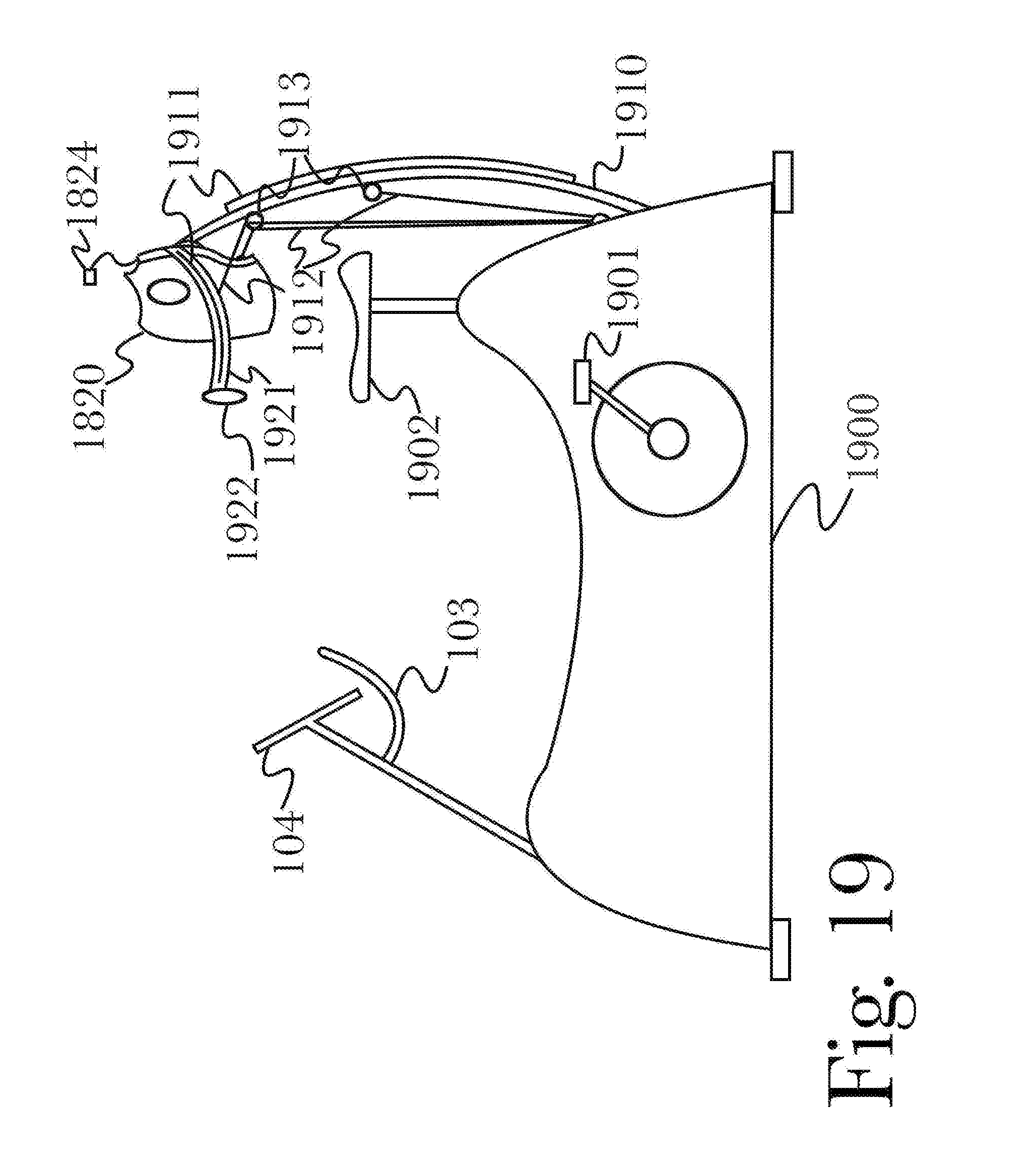
D00020
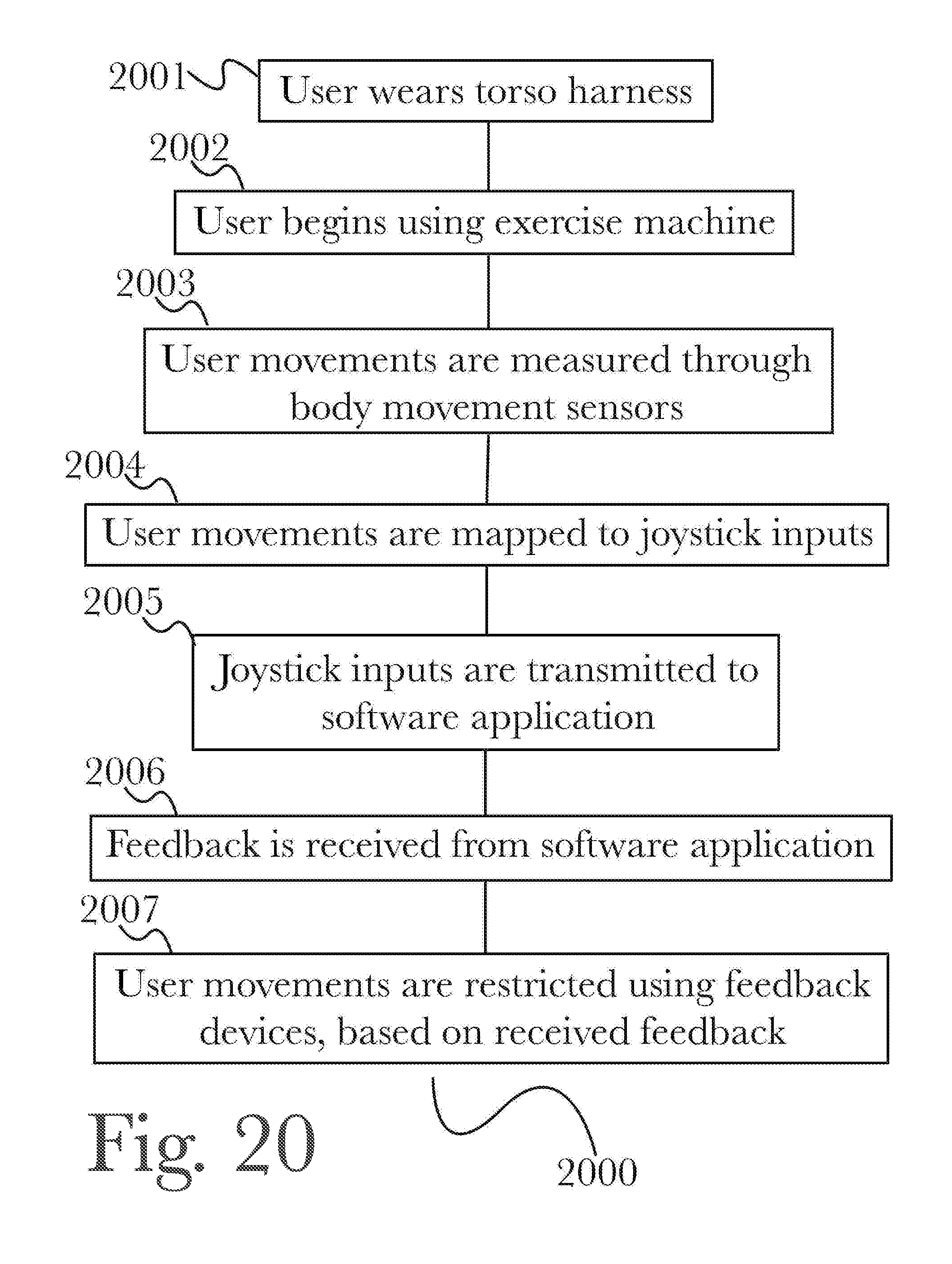
D00021

D00022

D00023

D00024

D00025
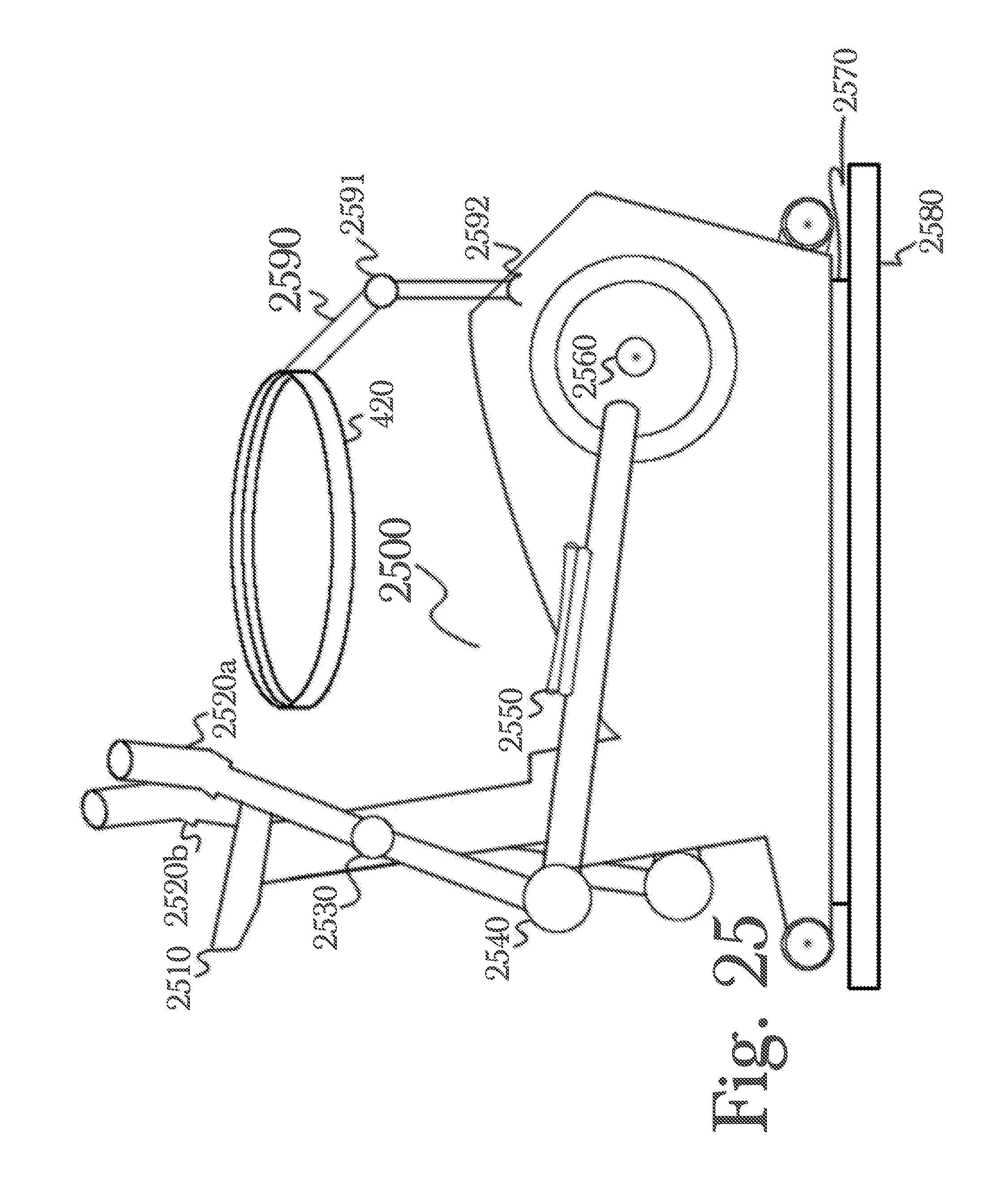
D00026
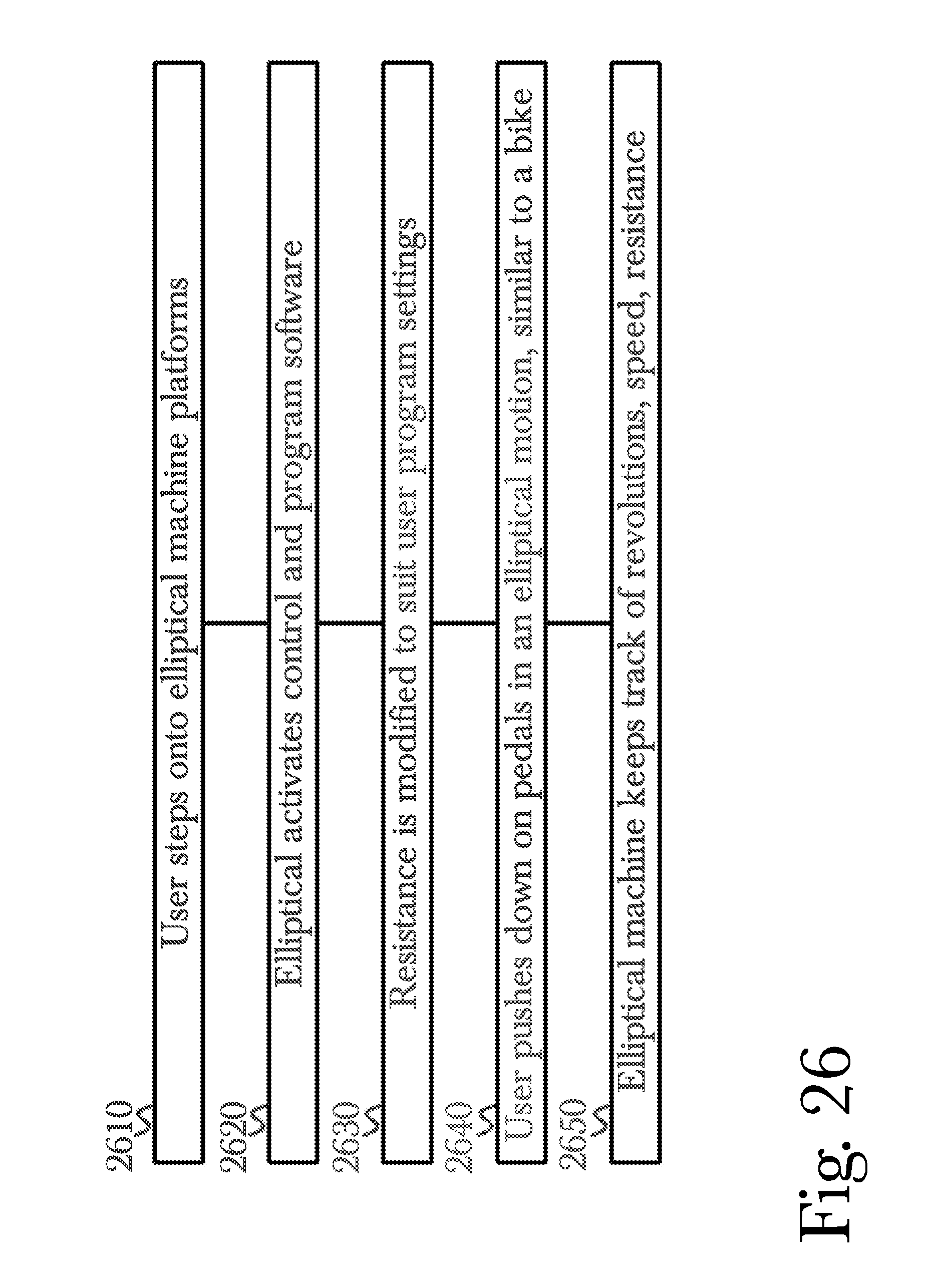
XML
uspto.report is an independent third-party trademark research tool that is not affiliated, endorsed, or sponsored by the United States Patent and Trademark Office (USPTO) or any other governmental organization. The information provided by uspto.report is based on publicly available data at the time of writing and is intended for informational purposes only.
While we strive to provide accurate and up-to-date information, we do not guarantee the accuracy, completeness, reliability, or suitability of the information displayed on this site. The use of this site is at your own risk. Any reliance you place on such information is therefore strictly at your own risk.
All official trademark data, including owner information, should be verified by visiting the official USPTO website at www.uspto.gov. This site is not intended to replace professional legal advice and should not be used as a substitute for consulting with a legal professional who is knowledgeable about trademark law.