Proximal-end Securement Of A Minimally Invasive Working Channel
Chegini; Salman ; et al.
U.S. patent application number 16/358372 was filed with the patent office on 2019-07-11 for proximal-end securement of a minimally invasive working channel. This patent application is currently assigned to Medos International Sarl. The applicant listed for this patent is Medos International Sarl. Invention is credited to Salman Chegini, Piet Hinoul, Richard Kocharian, Joern Richter, Peter Senn, Daniel Thommen.
| Application Number | 20190209002 16/358372 |
| Document ID | / |
| Family ID | 60660996 |
| Filed Date | 2019-07-11 |
View All Diagrams
| United States Patent Application | 20190209002 |
| Kind Code | A1 |
| Chegini; Salman ; et al. | July 11, 2019 |
PROXIMAL-END SECUREMENT OF A MINIMALLY INVASIVE WORKING CHANNEL
Abstract
The present invention is directed at minimally invasive systems in which the proximal end portion of the working channel has either zero or a limited range of movement in the lateral direction. A first embodiment has a slidable collar attached to a pair of flanges, wherein movement of the collar is bounded by an annular frame. A second embodiment has a substantially spherical element attached to the tube. A third embodiment has a plurality of caps. A fourth embodiment is adapted for a larger working channel.
| Inventors: | Chegini; Salman; (Bern, CH) ; Richter; Joern; (Kandern, DE) ; Thommen; Daniel; (Liestal, CH) ; Senn; Peter; (Waldenberg, CH) ; Hinoul; Piet; (Basking Ridge, NJ) ; Kocharian; Richard; (Princeton, NJ) | ||||||||||
| Applicant: |
|
||||||||||
|---|---|---|---|---|---|---|---|---|---|---|---|
| Assignee: | Medos International Sarl Le Locle CH |
||||||||||
| Family ID: | 60660996 | ||||||||||
| Appl. No.: | 16/358372 | ||||||||||
| Filed: | March 19, 2019 |
Related U.S. Patent Documents
| Application Number | Filing Date | Patent Number | ||
|---|---|---|---|---|
| 15695046 | Sep 5, 2017 | 10264959 | ||
| 16358372 | ||||
| 14546620 | Nov 18, 2014 | 10111712 | ||
| 15695046 | ||||
| 14481822 | Sep 9, 2014 | 9924979 | ||
| 14546620 | ||||
| Current U.S. Class: | 1/1 |
| Current CPC Class: | A61B 1/3135 20130101; A61B 2017/0262 20130101; A61B 2017/7073 20130101; A61B 17/7067 20130101; A61B 2017/3405 20130101; A61B 17/3403 20130101; A61B 2090/571 20160201; A61B 17/7074 20130101; A61B 1/00071 20130101; A61B 1/00078 20130101; A61B 2017/3488 20130101; A61B 17/0218 20130101; A61B 17/3421 20130101; A61B 90/50 20160201; A61B 2017/00261 20130101; A61B 2017/00845 20130101 |
| International Class: | A61B 1/313 20060101 A61B001/313; A61B 1/00 20060101 A61B001/00; A61B 17/34 20060101 A61B017/34; A61B 90/50 20060101 A61B090/50; A61B 17/02 20060101 A61B017/02; A61B 17/70 20060101 A61B017/70 |
Claims
1. A minimally-invasive surgical access system, comprising; a) a tube having an outer wall, a longitudinal bore, a proximal end portion and a distal end portion; b) a sliding tab comprising a collar having a pair of opposed flanges extending therefrom, wherein the collar is slidable along the outer wall of the tube; and c) an annular frame having a pair of substantially opposed slots, wherein the flanges of the collar respectively extend through the slots of the annular frame, and wherein the tube extends through the annular frame.
2. The system of claim 1 further comprising: d) an arm extending from a stationary unit, wherein the arm is attached to the annular frame.
3. The system of claim 1 wherein the collar comprises a threaded hole, and further comprising: d) a set screw received in the threaded hole of the collar.
4. The system of claim 3 wherein the set screw can extend through the collar and contact the outer wall of the tube in the proximal end portion of the tube to lock the collar to the tube.
5. The system of claim 1 wherein each flange comprises a portion of a spherical surface and each slot describes an arc, wherein the flange mates with the slot.
6. The system of claim 1 wherein the distal end portion of the tube has a docking feature adapted to dock to bone or cartilage.
7. The system of claim 1 wherein the collar does not contact the annular frame.
8. The system of claim 3 wherein the annular frame has a cutout.
9. The system of claim 8 wherein the cutout aligns radially with the set screw.
10. The system of claim 1 wherein the proximal portion of the tube is able to move in a substantially frustoconcical volume when the distal end portion of the tube is fixed.
11. A minimally-invasive surgical access system, comprising; a) a tube having an outer wall, a longitudinal bore, a proximal end portion, a distal end portion, and a substantially spherical element radially surrounding a segment of the outer wall; b) a sliding tab having a base and a pair of opposed flanges extending therefrom; the base having a hole therethrough defining a rim having a static portion and a slidable portion, c) an annular frame having a pair of substantially opposed slots, wherein each flange of the sliding tab extends through a respective slot of the annular frame, wherein the tube extends through the annular frame, and wherein the static portion of the rim releasably contacts a first portion of the substantially spherical element and the slidable portion of the rim releasably contacts a second portion of the substantially spherical element.
12. The system of claim 11 further comprising: d) an arm extending from a stationary unit, wherein the arm is attached to the annular frame.
13. The system of claim 11 wherein the base comprises a first cutout, and further comprising: d) a sliding door slidably received in the cutout.
14. The system of claim 13 wherein the sliding door comprises the slidable portion of the rim.
15. The system of claim 14 wherein the slidable portion of the rim comprises a substantially hemispherical portion, wherein the substantially hemispherical portion releasably mates with the second portion of the substantially spherical element.
16. The system of claim 13 wherein the sliding door is slidably actuated by a screw.
17. The system of claim 13 wherein the annular frame has a second cutout.
18. The system of claim 11 wherein the distal end portion of the tube has a docking feature adapted to dock to bone or cartilage.
19. The system of claim 11 wherein each flange is flat and each slot is substantially rectangular, wherein the flange mates with the slot.
20. The system of claim 19 wherein the second cutout aligns radially with the set screw.
21. The system of claim 11 wherein the static portion of the rim comprises a substantially hemispherical portion that releasably mates with the first portion of the substantially spherical element.
22. The system of claim 11 wherein the flanges of the sliding tab are not orthogonal to the tube.
23. A minimally invasive surgical access system, comprising; a) an upper cap describing a first portion of a substantially spherical surface, b) an middle cap describing a second portion of the substantially spherical surface and having a central hole, c) a lower cap describing a third portion of the substantially spherical surface, d) a tube having an outer wall having an attachment portion, a longitudinal bore, a proximal end portion, a distal end portion, wherein the upper cap and the lower cap are attached to and radially extend from the outer wall of the tube, wherein at least one of the upper cap and the lower cap is removably attached to the outer wall of the tube, wherein the tube is received in the central hole of the middle cap, and wherein the middle cap is received between the upper cap and the lower cap.
24. The system of claim 23 wherein the upper cap is located proximal to the lower cap.
25. The system of claim 23 wherein the middle cap has a fixation element for fixation to a stationary unit.
26. The system of claim 25 further comprising: e) an arm extending from the stationary unit, wherein the arm is attached to the fixation element.
27. The system of claim 23 wherein the proximal portion of the tube is able to move in a substantially frustoconcical volume when the distal end portion of the tube is fixed.
28. The system of claim 23 wherein the distal end portion of the tube has a docking feature adapted to dock to bone.
29. The system of claim 23 wherein the upper cap, middle cap, and lower cap are located in a proximal-most quarter of the tube.
30. The system of claim 23 wherein one of the upper or lower cap has a threaded hole, the outer wall has a threaded portion, and the cap having the threaded hole is threadably received on the threaded portion of the outer wall of the tube.
31. The system of claim 23 wherein one of the upper cap and the lower cap is removably attached to the outer wall of the tube, and the other of the caps is integrally attached to the outer wall of the tube.
32. The system of claim 23 wherein both of the upper cap and the lower cap are removably attached to the outer wall of the tube.
33. The system of claim 23 wherein both of the upper cap and the lower cap are threadably attached to the outer wall of the tube.
34. An apparatus comprising: a) an arm having a proximal end portion connected to a stationary object and a distal end portion, b) a medial-lateral bar connected to the distal end portion of the arm and having a first rail; c) a cranial-caudal bar having: i) a first rail in slidable engagement with the first rail of the medial-lateral bar in a first direction and ii) a second rail extending substantially perpendicularly from the first rail of the cranial-caudal bar; d) a working channel construct comprising: i) a tube having an outer surface and a proximal end portion, and ii) a slider attached to the outer surface of the tube and having a first rail in slidable engagement with the second rail of the cranial-caudal bar.
35. The apparatus of claim 34 wherein the cranial-caudal bar has a release button for releasable attachment to the medial-lateral bar.
36. The apparatus of claim 34 wherein the slider has a release mechanism for releasable attachment to the cranial-caudal bar.
37. The apparatus of claim 34 wherein the medial-lateral bar has a first window therein for slidable reception of the cranial-caudal bar.
38. The apparatus of claim 34 wherein the cranial-caudal bar has a third rail extending from the first rail of the cranial-caudal bar in a direction substantially parallel to the second rail of the cranial-caudal bar.
39. The apparatus of claim 38 wherein the slider further comprises iii) a second rail substantially parallel to the first rail of the slider, wherein the second rail of the slider is in slidable engagement with the third rail of the cranial-caudal bar.
40. The apparatus of claim 39 wherein the tube is disposed between the second and third rails of the cranial caudal bar.
41. The apparatus of claim 40 wherein a fourth rail connects the second and third rails of the cranial-caudal bar to form a second window, and the tube extends through the second window.
42. The apparatus of claim 34 wherein the first rail of the medial-lateral bar and the first rail of the cranial-caudal bar have mating teeth thereon.
43. The apparatus of claim 34 wherein the second rail of the cranial-caudal bar and the first rail of the slider have mating teeth thereon.
44. The apparatus of claim 34 further comprising: e) a medical device located within the tube.
45. The apparatus of claim 44 wherein the medical device is an instrument.
46. The apparatus of claim 44 wherein the medical device is an implant.
47. The apparatus of claim 34 wherein the first rail of the medial-lateral bar and the first rail of the cranial-caudal bar have matching arcuate shapes.
48. The apparatus of claim 34 wherein the second rail of the cranial-caudal bar and the first rail of the slider have matching arcuate shapes.
49. The apparatus of claim 34 wherein the slider is attached to the outer surface of the tube at the proximal end portion of the tube.
50. The apparatus of claim 34 wherein the outer surface of the tube at the proximal end portion of the tube has a thread thereon, the slider has a window having a matching thread thereon, and the slider is threadably engaged with the proximal end portion of the tube.
51. The apparatus of claim 34 wherein the first rail of the cranial-caudal is in slidable engagement with the first rail of the medial-lateral bar by virtue of a bolt-slot connection.
52. The apparatus of claim 34 wherein the tube has a distal end centerpoint, and the distal end centerpoint remains at the same location in space when a position of the slider along the second rail of the cranial-caudal bar is changed.
53. An apparatus comprising: a) an arm having a proximal end portion connected to a stationary object and a distal end portion, b) a medial-lateral bar connected to the distal end portion of the arm and having a first rail; c) a cranial-caudal bar having: i) a first rail in slidable engagement with the first rail of the medial-lateral bar in a first direction and ii) a second rail extending substantially perpendicularly from the first rail of the cranial-caudal bar; d) a surgical instrument construct comprising: i) an endoscope having an outer surface and a proximal end portion, and ii) a slider attached to the outer surface of the endoscope and having a first rail in slidable engagement with the second rail of the cranial-caudal bar.
54. The apparatus of claim 53 wherein the cranial-caudal bar has a release button for releasable attachment to the medial-lateral bar.
55. The apparatus of claim 53 wherein the slider has a release mechanism for releasable attachment to the cranial-caudal bar.
56. The apparatus of claim 53 wherein the medial-lateral bar has a first window therein for slidable reception of the cranial-caudal bar.
57. The apparatus of claim 53 wherein the cranial-caudal bar has a third rail extending from the first rail of the cranial-caudal bar in a direction substantially parallel to the second rail of the cranial-caudal bar.
58. The apparatus of claim 57 wherein the slider further comprises iii) a second rail substantially parallel to the first rail of the slider, wherein the second rail of the slider is in slidable engagement with the third rail of the cranial-caudal bar.
59. The apparatus of claim 58 wherein the endoscope is disposed between the second and third rails of the cranial caudal bar.
60. The apparatus of claim 59 wherein a fourth rail connects the second and third rails of the cranial-caudal bar to form a second window, and the endoscope extends through the second window.
61. The apparatus of claim 53 wherein the first rail of the medial-lateral bar and the first rail of the cranial-caudal bar have mating teeth thereon.
62. The apparatus of claim 53 wherein the second rail of the cranial-caudal bar and the first rail of the slider have mating teeth thereon.
63. The apparatus of claim 53 wherein the first rail of the medial-lateral bar and the first rail of the cranial-caudal bar have matching arcuate shapes.
64. The apparatus of claim 53 wherein the second rail of the cranial-caudal bar and the first rail of the slider have matching arcuate shapes.
65. The apparatus of claim 53 wherein the slider is attached to the outer surface of the endoscope at the proximal end portion of the endoscope.
66. The apparatus of claim 53 wherein the outer surface of the endoscope at the proximal end portion of the endoscope has a thread thereon, the slider has a window having a matching thread thereon, and the slider is threadably engaged with the proximal end portion of the endoscope.
67. The apparatus of claim 53 wherein the first rail of the cranial-caudal is in slidable engagement with the first rail of the medial-lateral bar by virtue of a bolt-slot connection.
68. The apparatus of claim 53 wherein the endoscope has a distal end centerpoint, and the distal end centerpoint remains at the same location in space when a position of the slider along the second rail of the cranial-caudal bar is changed.
Description
[0001] This application is a continuation of U.S. application Ser. No. 15/695,046, filed on Sep. 5, 2017. U.S. application Ser. No. 15/695,046 is a continuation-in-part of U.S. application Ser. No. 14/546,620, filed on Nov. 18, 2014 (issued as U.S. Pat. No. 10,111,712). U.S. application Ser. No. 14/546,620 is a continuation-in-part of U.S. application Ser. No. 14/481,822, filed on Sep. 9, 2014 (issued as U.S. Pat. No. 9,924,979). The entire contents of each of these applications are hereby incorporated by reference.
BACKGROUND OF THE INVENTION
[0002] The general trend in the treatment of the spinal pathologies is toward minimally invasive approaches to reduce the trauma on the surrounding tissues during the operation. For treatment of the lumbar spine pathologies, a percutaneous approach may be chosen within a working channel of 4-12 mm. The working channel serves as a safety barrier between the working instruments and the sensitive tissues (e.g. nerves and blood vessels) during the operation. The process of treatment including disc removal, endplate preparation, implant insertion and graft material insertion should be performed through the working channel.
SUMMARY OF THE INVENTION
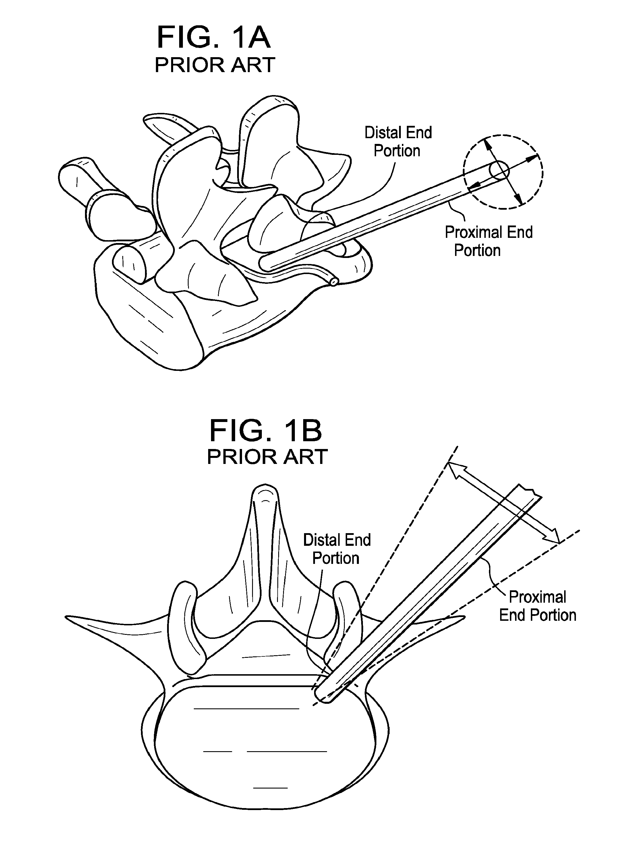
[0003] In order to ensure the safety of these procedures, the distal end portion of the working channel (from surgeon's perspective) should be secured/anchored onto desired points (see FIGS. 1A and 1B). Typically, these points are either bone or disc tissue. In addition to the fixation of the distal end portion of the working channel, depending on the procedure that is being performed, the proximal end portion of the working channel needs to be able to either move laterally, move cranially/caudally, or be substantially fixed. For example, during disc removal, the surgeon might want to change the angle of the working channel in order to gain better access to more of the remaining disc tissue (see FIG. 1B). At the same time, it might be desired that this motion be limited to a given range, and to be fixed in the axial direction. Furthermore, in some instances, it might be desired for the proximal portion of the working channel to be fully fixed in order to create a two-point fixed channel between proximal and distal portion.
[0004] Therefore, the present invention is directed at minimally invasive systems in which the proximal end portion of the working channel has either zero or a limited range of movement in the lateral direction.
[0005] Therefore, in accordance with the present invention, there is provided a minimally-invasive surgical access system, comprising;
[0006] a) a tube having an outer wall, a longitudinal bore, a proximal end portion and a distal end portion;
[0007] b) a sliding tab comprising a collar having a pair of opposed flanges extending therefrom, wherein the collar is slidable along the outer wall of the tube; and
[0008] c) an annular frame having a pair of substantially opposed slots, wherein the flanges of the collar respectively extend through the slots of the annular frame, and wherein the tube extends through the annular frame.
[0009] Therefore, in accordance with the present invention, there is provided a minimally-invasive surgical access system, comprising;
[0010] a) a tube having an outer wall, a longitudinal bore, a proximal end portion, a distal end portion, and a substantially spherical element radially surrounding a segment of the outer wall;
[0011] b) a sliding tab having a base and a pair of opposed flanges extending therefrom; the base having a hole therethrough defining a rim having a static portion and a slidable portion,
[0012] c) an annular frame having a pair of substantially opposed slots, wherein each flange of the sliding tab extends through a respective slot of the annular frame, wherein the tube extends through the annular frame, and wherein the static portion of the rim releasably contacts a first portion of the substantially spherical element and the slidable portion of the rim releasably contacts a second portion of the substantially spherical element.
[0013] Therefore, in accordance with the present invention, there is provided a minimally invasive surgical access system, comprising;
[0014] a) an upper cap describing a first portion of a substantially spherical surface,
[0015] b) an middle cap describing a second portion of the substantially spherical surface and having a central hole,
[0016] c) a lower cap describing a third portion of the substantially spherical surface,
[0017] d) a tube having an outer wall having an attachment portion, a longitudinal bore, a proximal end portion, a distal end portion, wherein the upper cap and the lower cap are attached to and radially extend from the outer wall of the tube, wherein at least one of the upper cap and the lower cap is removably attached to the outer wall of the tube, wherein the tube is received in the central hole of the middle cap, and wherein the middle cap is received between the upper cap and the lower cap.
[0018] In some aspects, the present invention is directed at surgical systems for supporting an endoscope or other instrument.
[0019] Therefore, in accordance with the present invention, there is provided a surgical system, comprising;
[0020] a) an instrument having an outer wall, a proximal end portion and a distal end portion;
[0021] b) a sliding tab comprising a collar having a pair of opposed flanges extending therefrom, wherein the collar is slidable along the outer wall of the instrument; and
[0022] c) an annular frame having a pair of substantially opposed slots, wherein the flanges of the collar respectively extend through the slots of the annular frame, and wherein the instrument extends through the annular frame.
[0023] In some embodiments, the instrument can be an endoscope or surgical visualization instrument.
[0024] Therefore, in accordance with the present invention, there is provided a surgical system, comprising;
[0025] a) an instrument having an outer wall, a proximal end portion, a distal end portion, and a substantially spherical element radially surrounding a segment of the outer wall;
[0026] b) a sliding tab having a base and a pair of opposed flanges extending therefrom; the base having a hole therethrough defining a rim having a static portion and a slidable portion,
[0027] c) an annular frame having a pair of substantially opposed slots, wherein each flange of the sliding tab extends through a respective slot of the annular frame, wherein the instrument extends through the annular frame, and wherein the static portion of the rim releasably contacts a first portion of the substantially spherical element and the slidable portion of the rim releasably contacts a second portion of the substantially spherical element.
[0028] In some embodiments, the instrument can be an endoscope or surgical visualization instrument.
[0029] Therefore, in accordance with the present invention, there is provided a surgical system, comprising;
[0030] a) an upper cap describing a first portion of a substantially spherical surface,
[0031] b) an middle cap describing a second portion of the substantially spherical surface and having a central hole,
[0032] c) a lower cap describing a third portion of the substantially spherical surface,
[0033] d) an instrument having an outer wall having an attachment portion, a proximal end portion, a distal end portion, wherein the upper cap and the lower cap are attached to and radially extend from the outer wall of the instrument, wherein at least one of the upper cap and the lower cap is removably attached to the outer wall of the instrument, wherein the instrument is received in the central hole of the middle cap, and wherein the middle cap is received between the upper cap and the lower cap.
[0034] In some embodiments, the instrument can be an endoscope or surgical visualization instrument.
DESCRIPTION OF THE FIGURES
[0035] FIGS. 1A and 1B disclose the desired ranges of motion for the systems of the present invention.
[0036] FIG. 2 discloses a first embodiment of the present invention having a slidable collar.
[0037] FIG. 3 discloses a second embodiment of the present invention having a substantially spherical element attached to the tube.
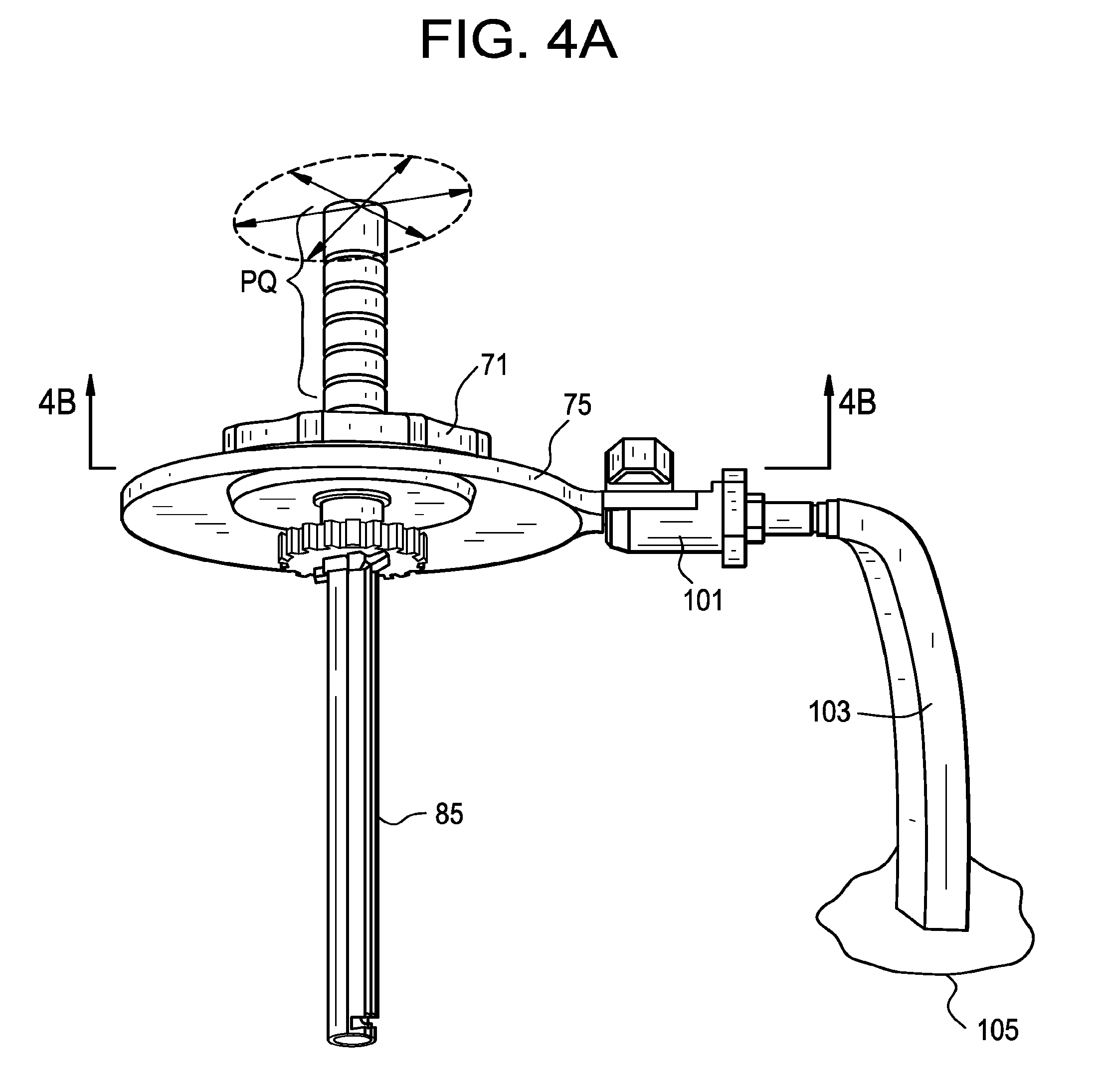
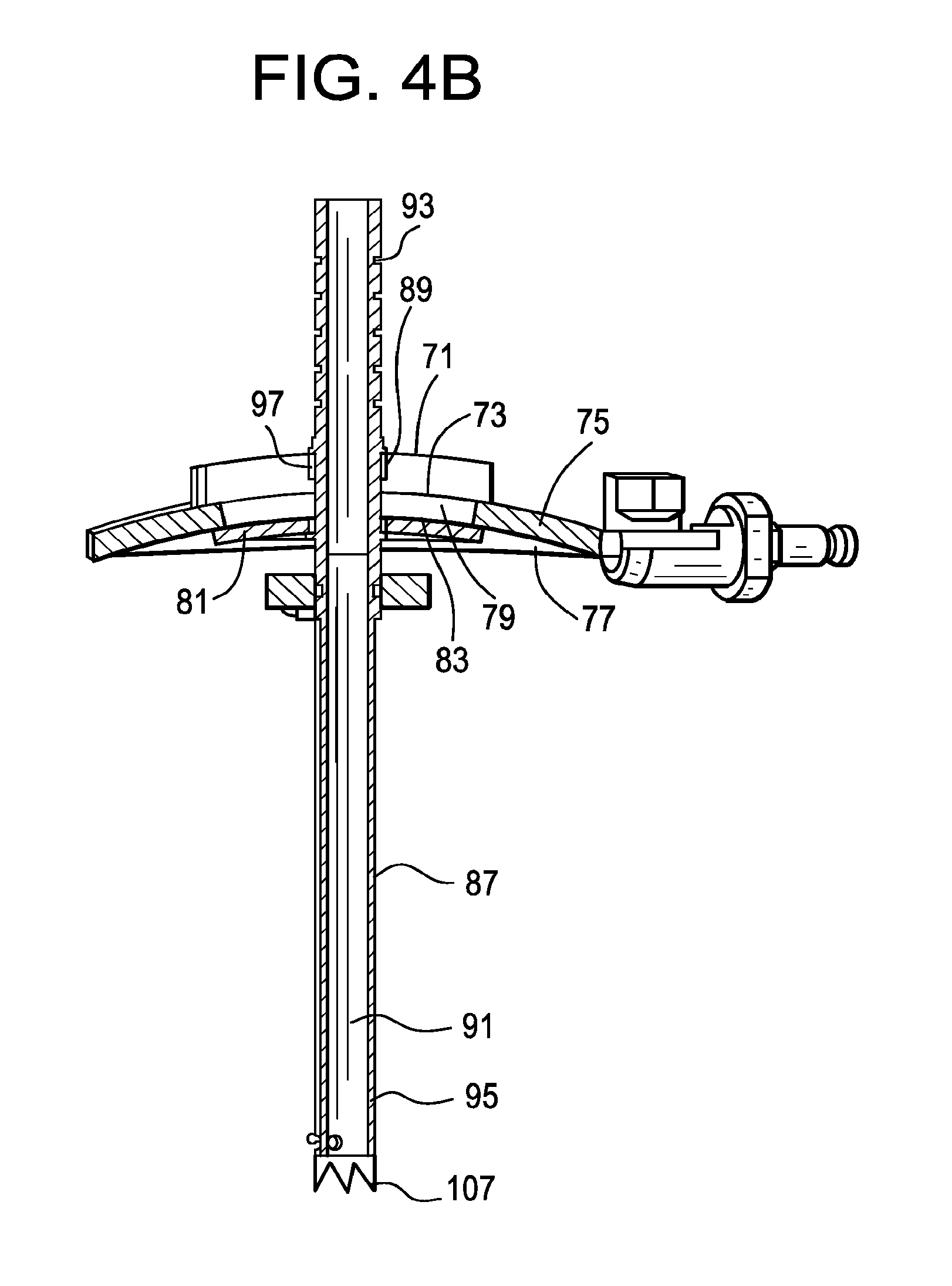
[0038] FIGS. 4A-B discloses a third embodiment of the present invention having a plurality of caps.
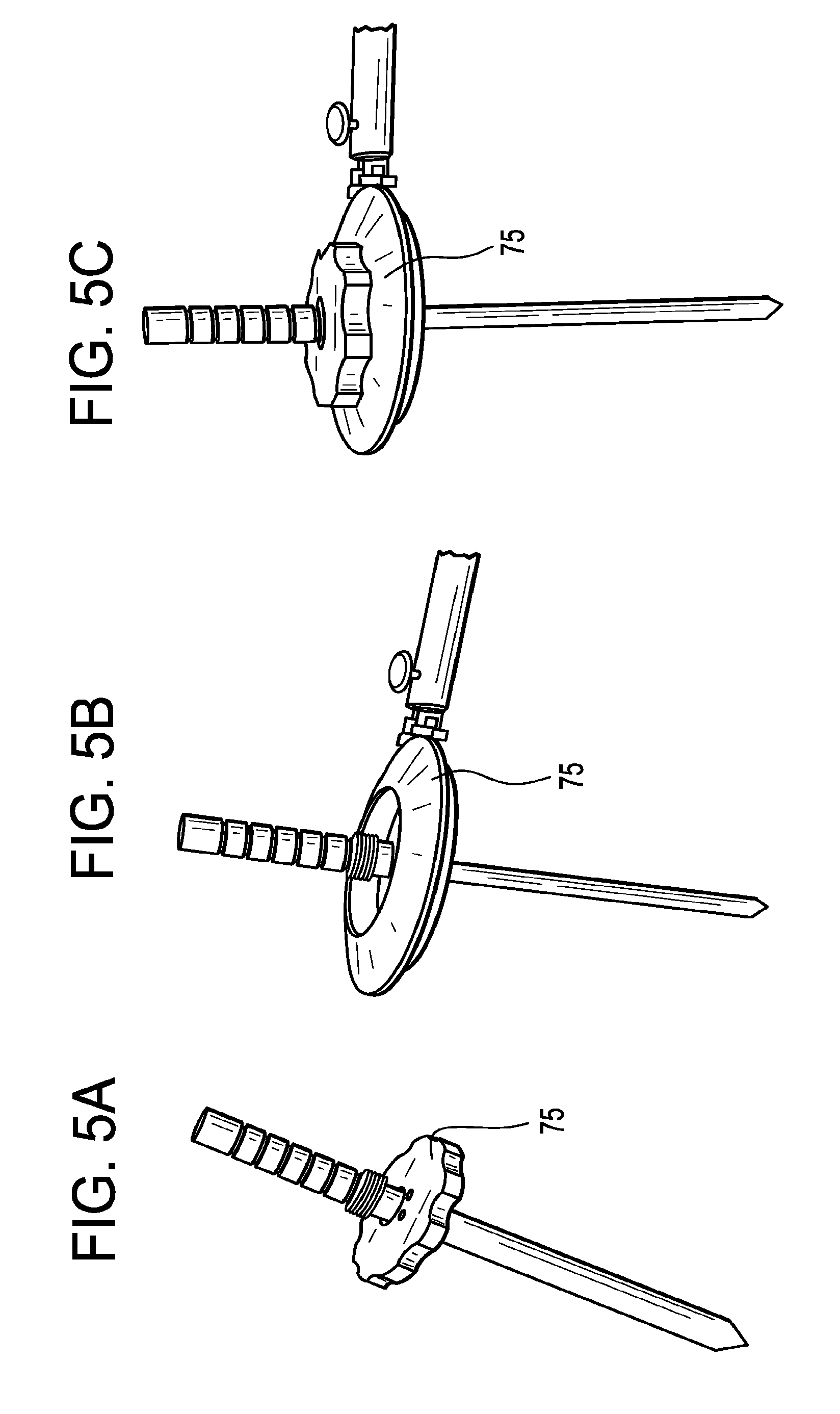
[0039] FIGS. 5A-C disclose the different steps of mounting and securing the embodiment of FIG. 4.
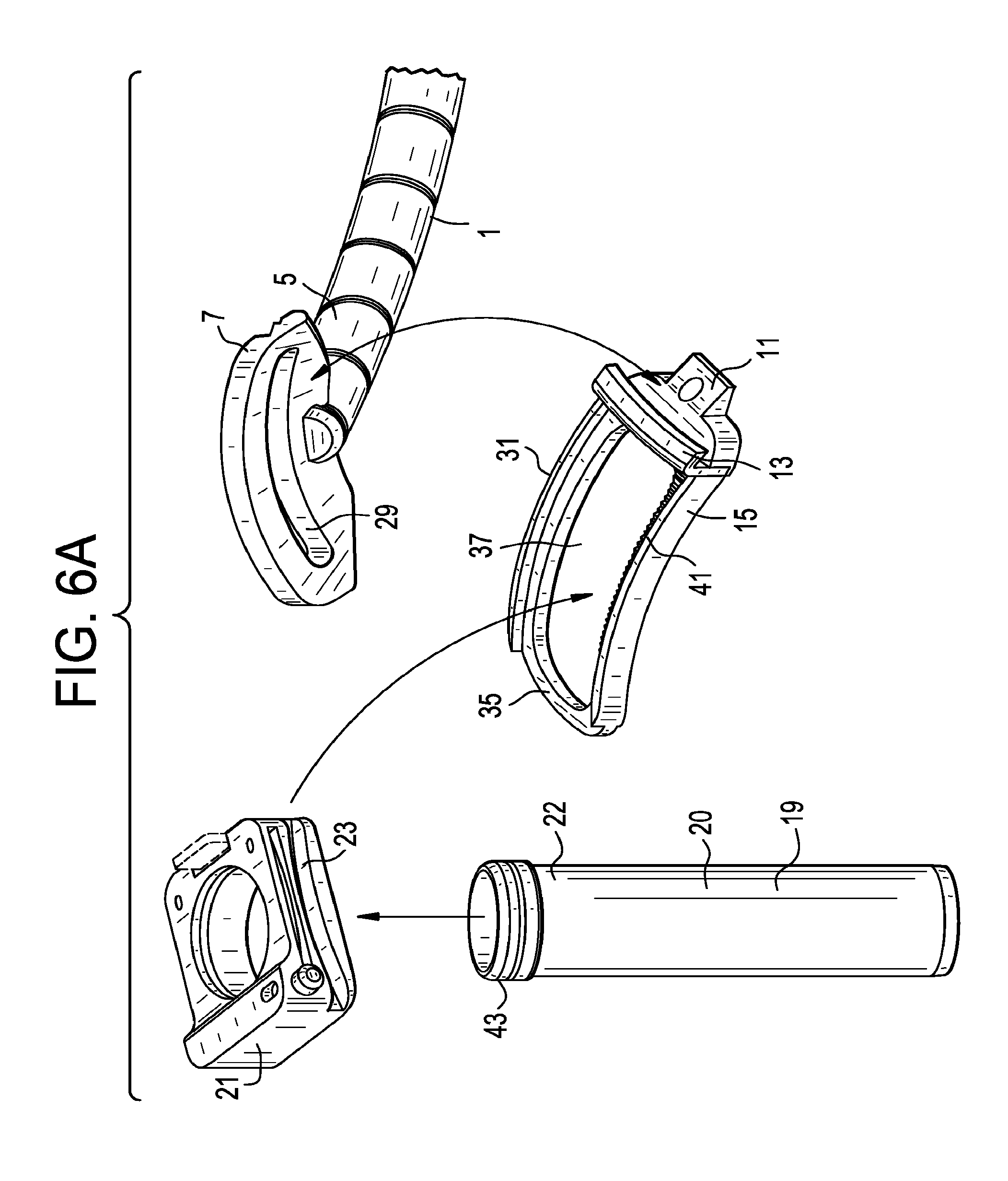
[0040] FIG. 6A discloses an exploded view of the apparatus of the fourth embodiment of the present invention.
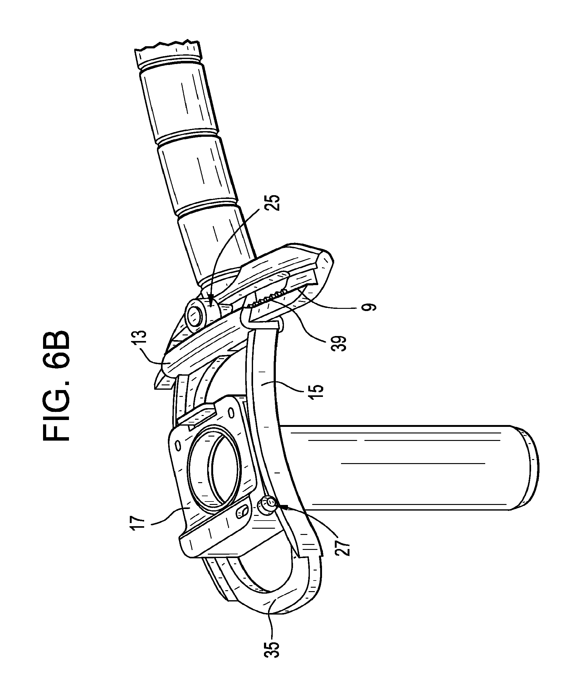
[0041] FIG. 6B discloses an assembled view of the apparatus of the fourth embodiment of the present invention.
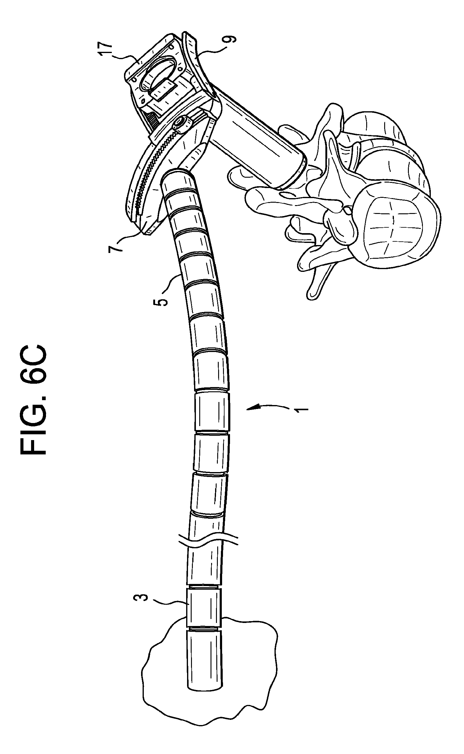
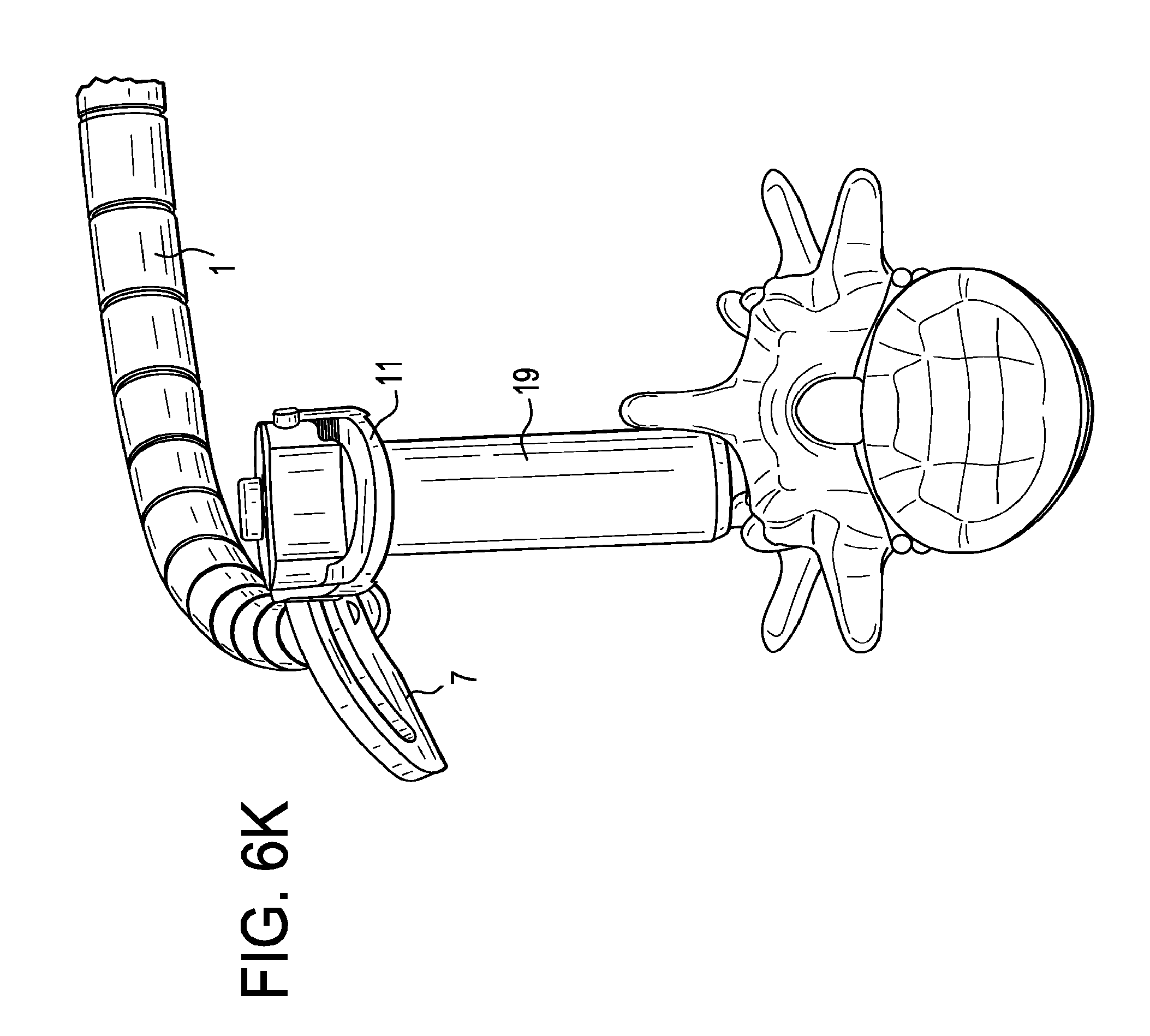
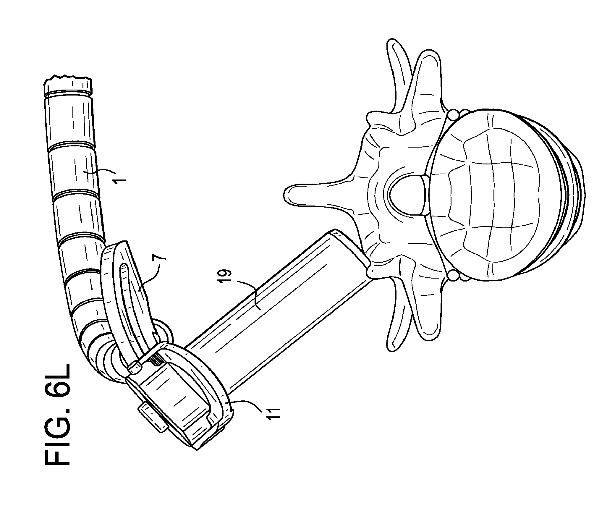
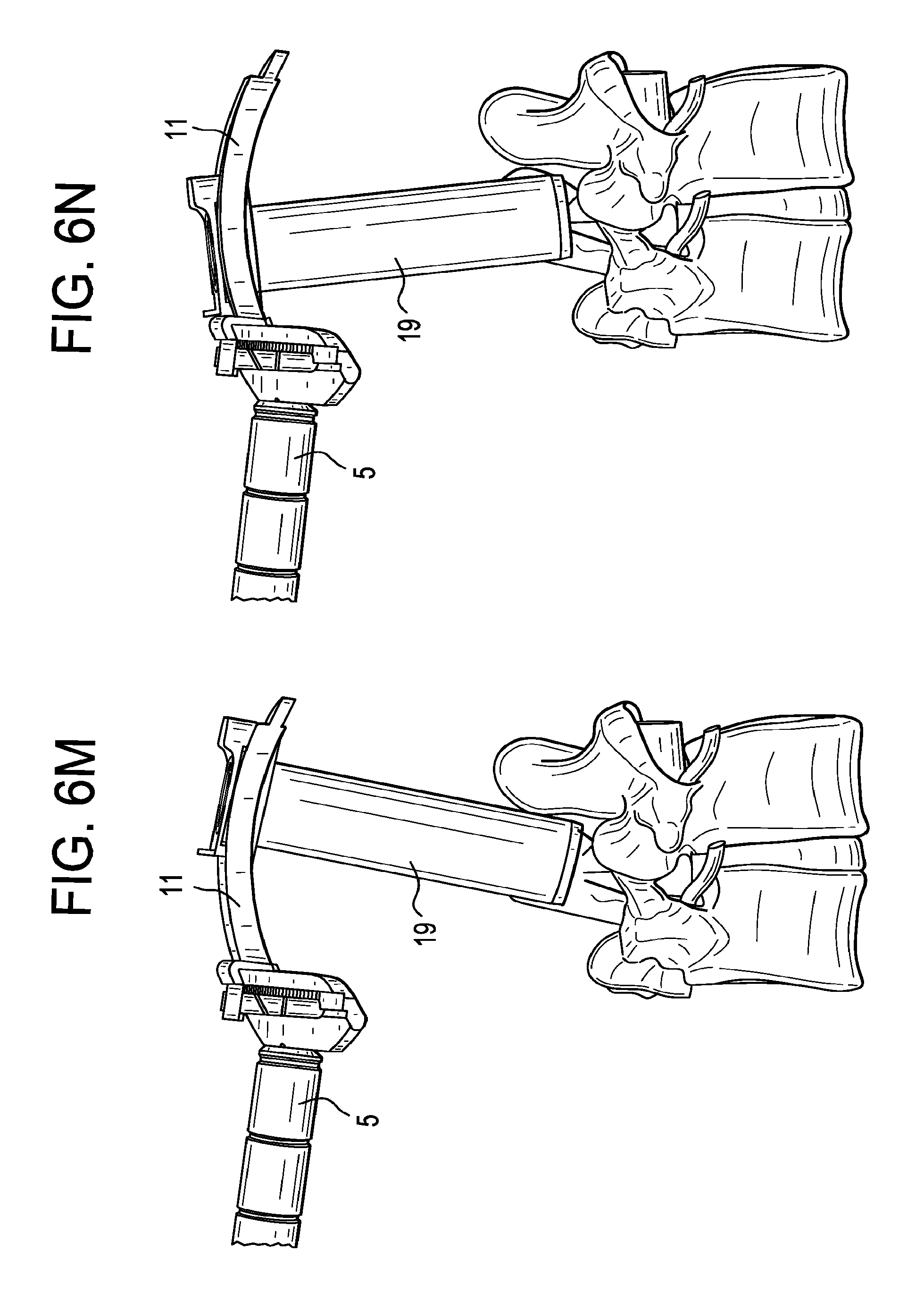
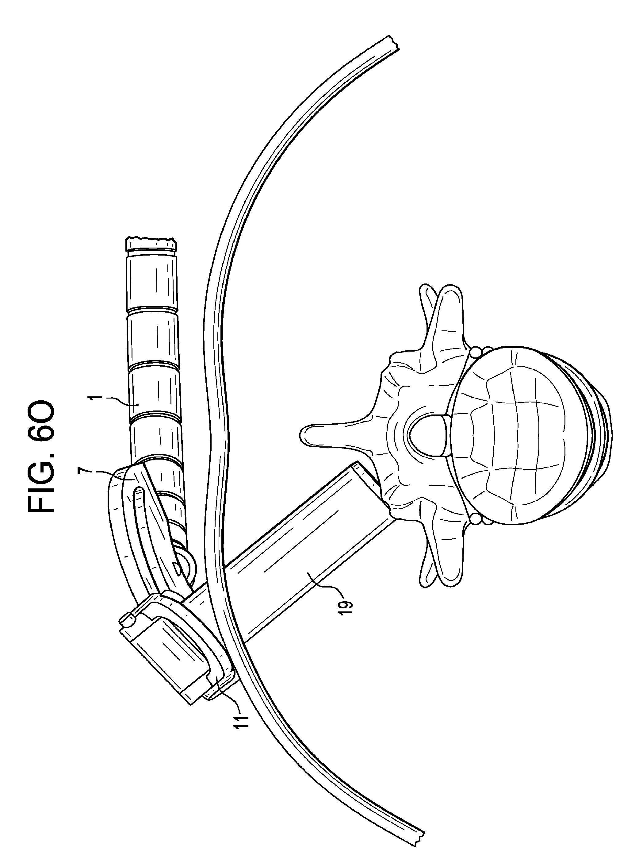
[0042] FIGS. 6C, 6K, 6L, 6M, 6N and 6O disclose various desirable orientations of the fourth apparatus embodiment relative to a functional spinal unit.
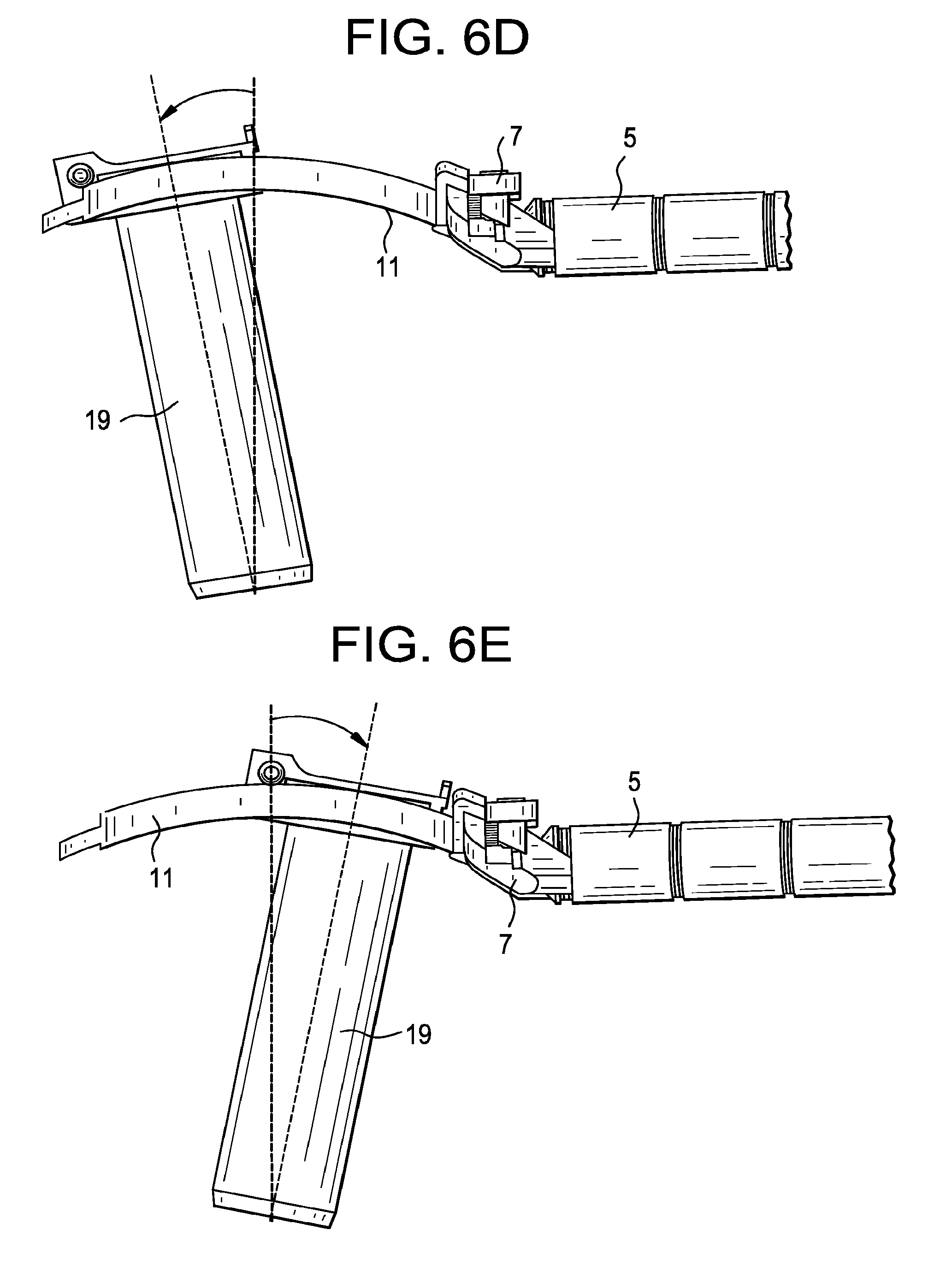
[0043] FIGS. 6D-6E disclose the possible cranial-caudal tilt angles of the fourth embodiment.
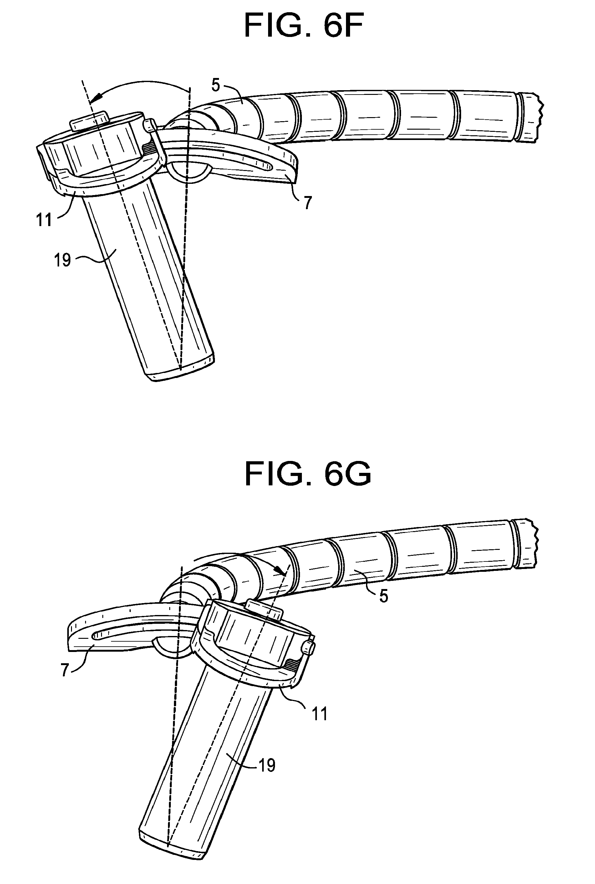
[0044] FIGS. 6F-6G disclose the possible medial-lateral tilt angles of the fourth embodiment.
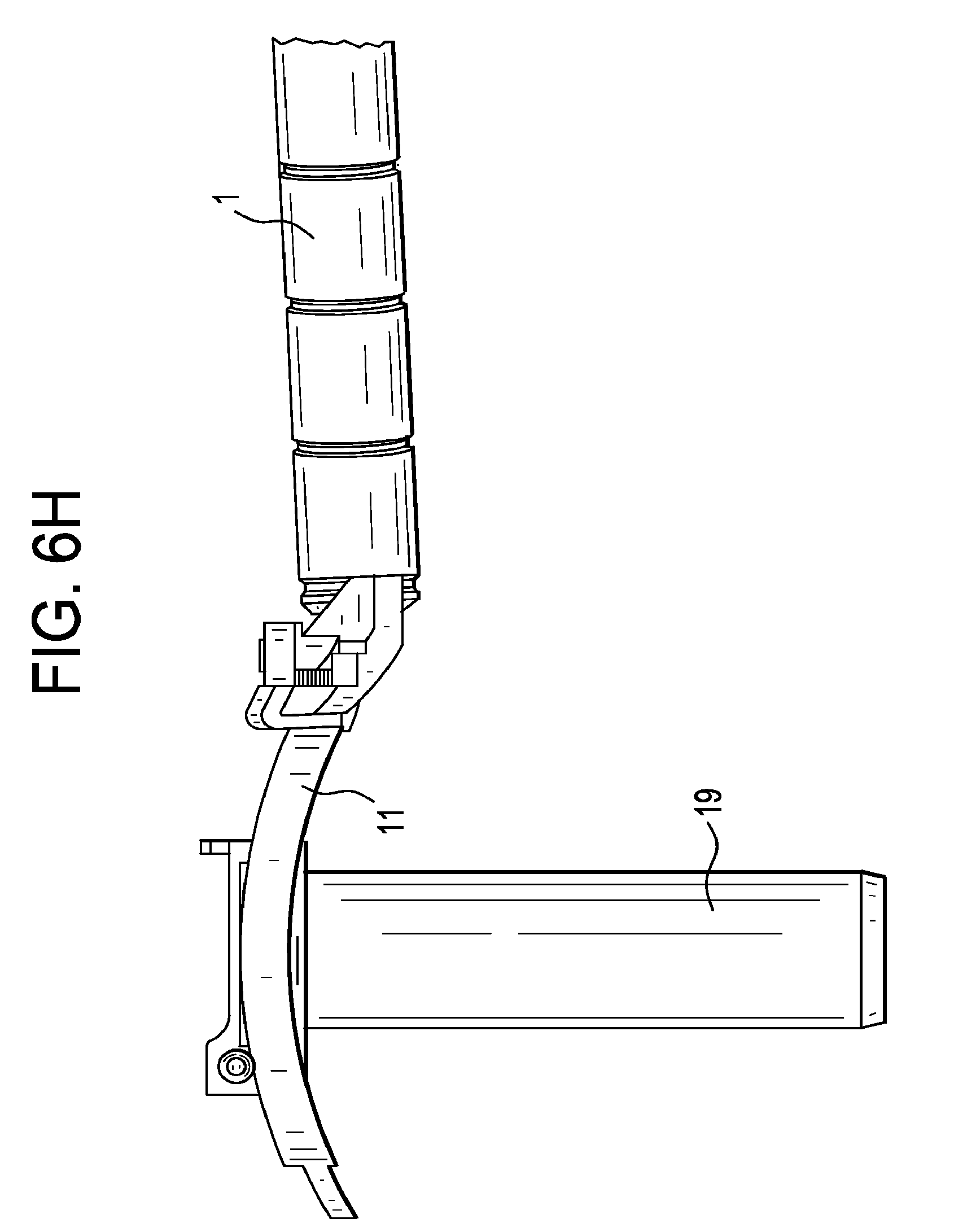
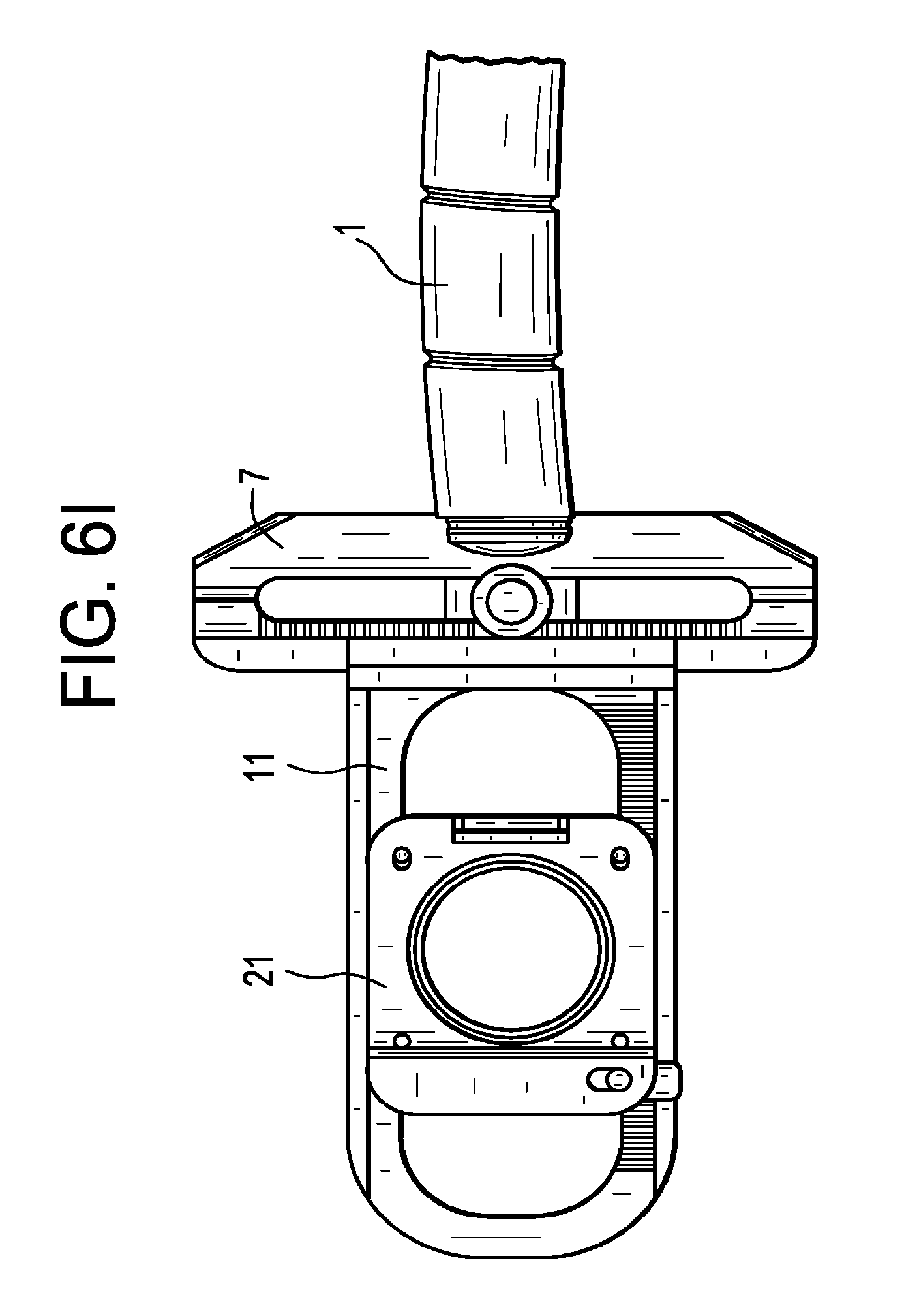
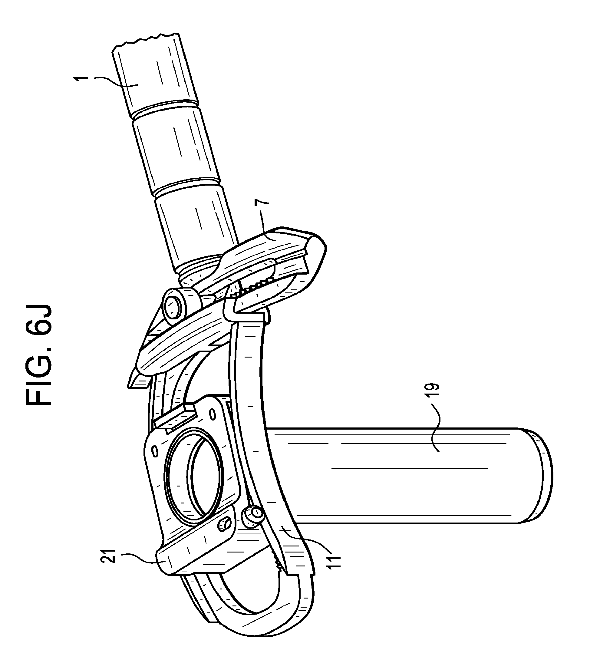
[0045] FIGS. 6H-6J disclose respective side, perspective and top views of the fourth embodiment apparatus.
[0046] FIGS. 6K-6O disclose various views of the apparatus in relation to the spine.
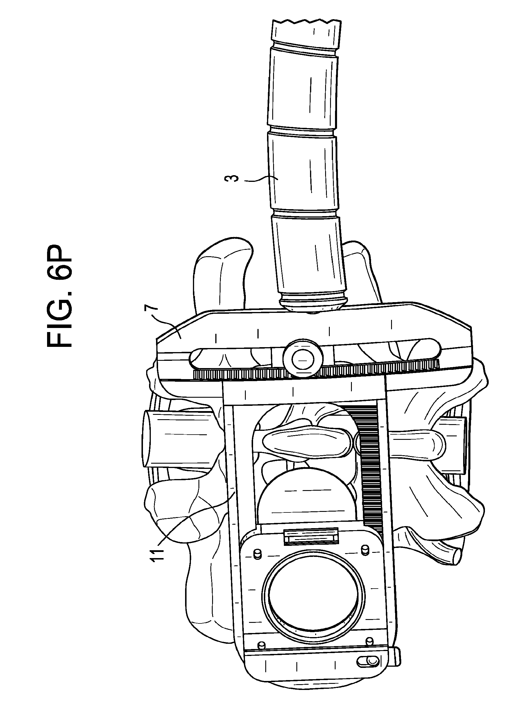
[0047] FIGS. 6P-6Q disclose views of the fourth embodiment apparatus wherein the medial-lateral bar runs parallel to the spine.
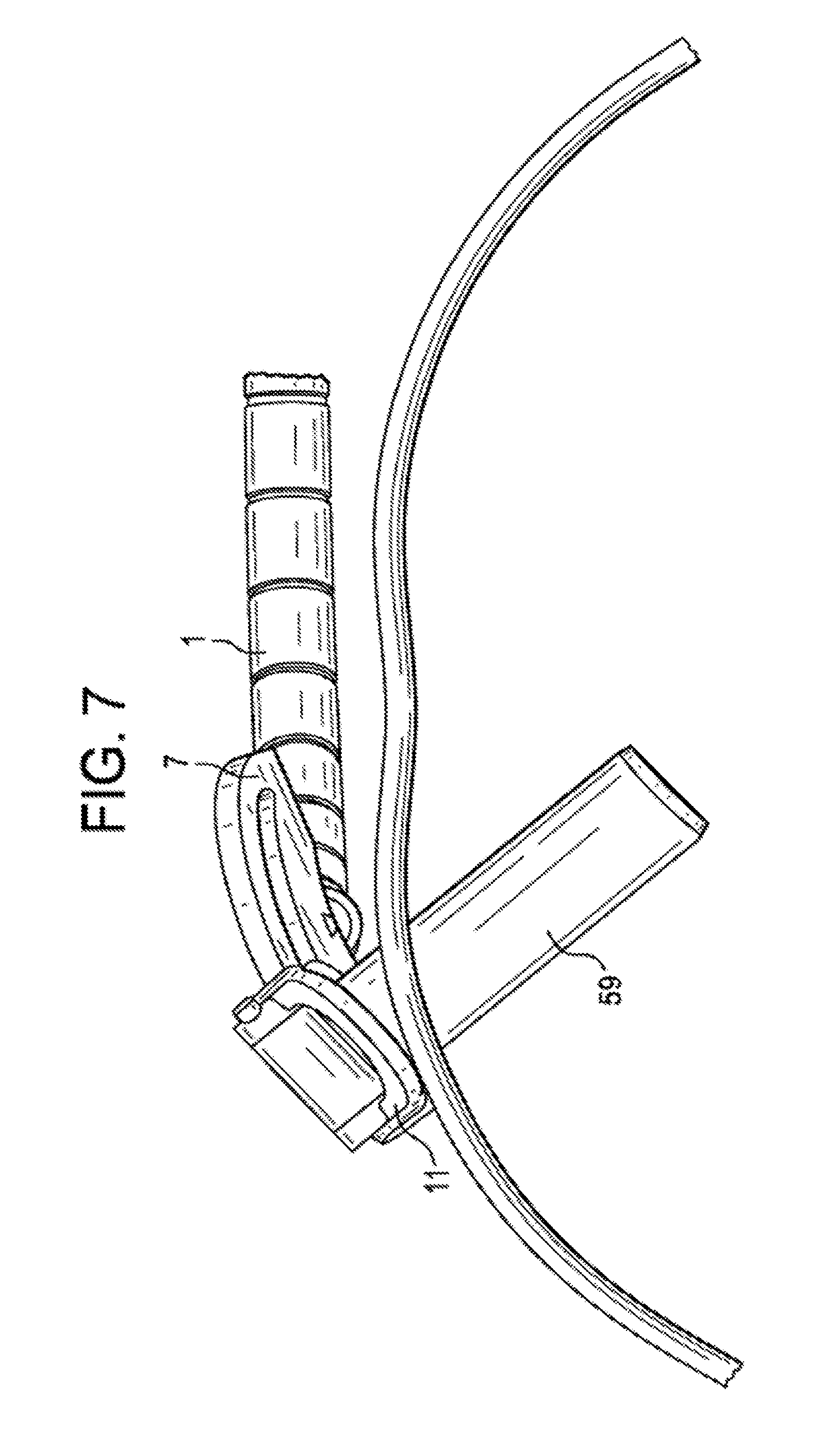
[0048] FIG. 7 discloses an apparatus for supporting a surgical instrument, such as an endoscope, in relation to a patient.
DETAILED DESCRIPTION OF THE INVENTION
[0049] For the purposes of the present invention, the "distal end portion of the tube" is the portion of the tube that is nearest to the patient and furthest from the surgeon when the tube is inserted into the patient, and the "proximal end portion of the tube" is the portion of the tube that is furthest from the patient and nearest to the surgeon when the tube is inserted into the patient. Also, "a working channel" and "a tube" are considered to be interchangeable. In some embodiments, a surgical instrument, or surgical visualization instrument, can be inserted through the tube, mounted to an interior or exterior of the tube, and/or movably or fixedly coupled to the tube. While tubes are described in many of the examples herein, the tube can be replaced with a surgical instrument, such as an endoscope or surgical visualization instrument.
[0050] In the following description, several concepts are described covering the subjects of a) limiting lateral motion of the proximal end portion of the tube, b) eliminating the lateral motion of the proximal end portion of the tube, and c) eliminating the axial motion of the proximal end portion of the tube.
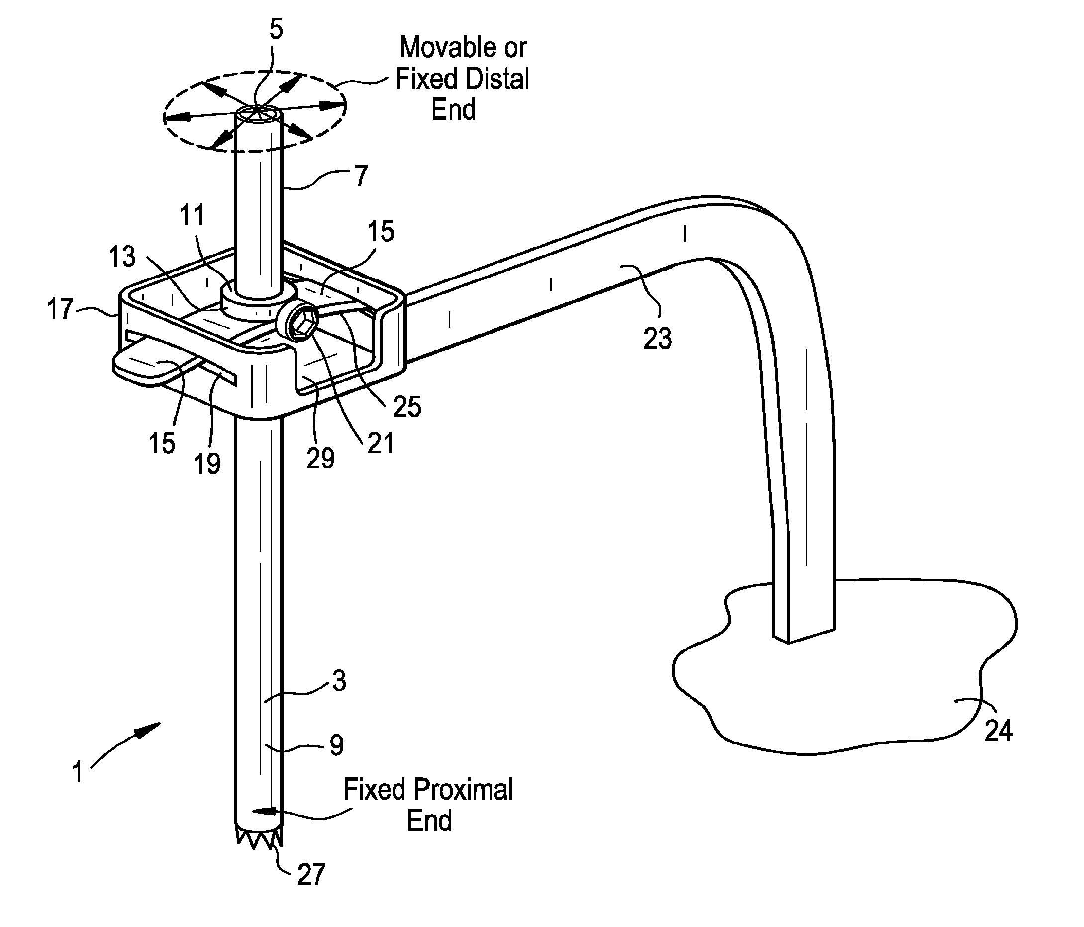
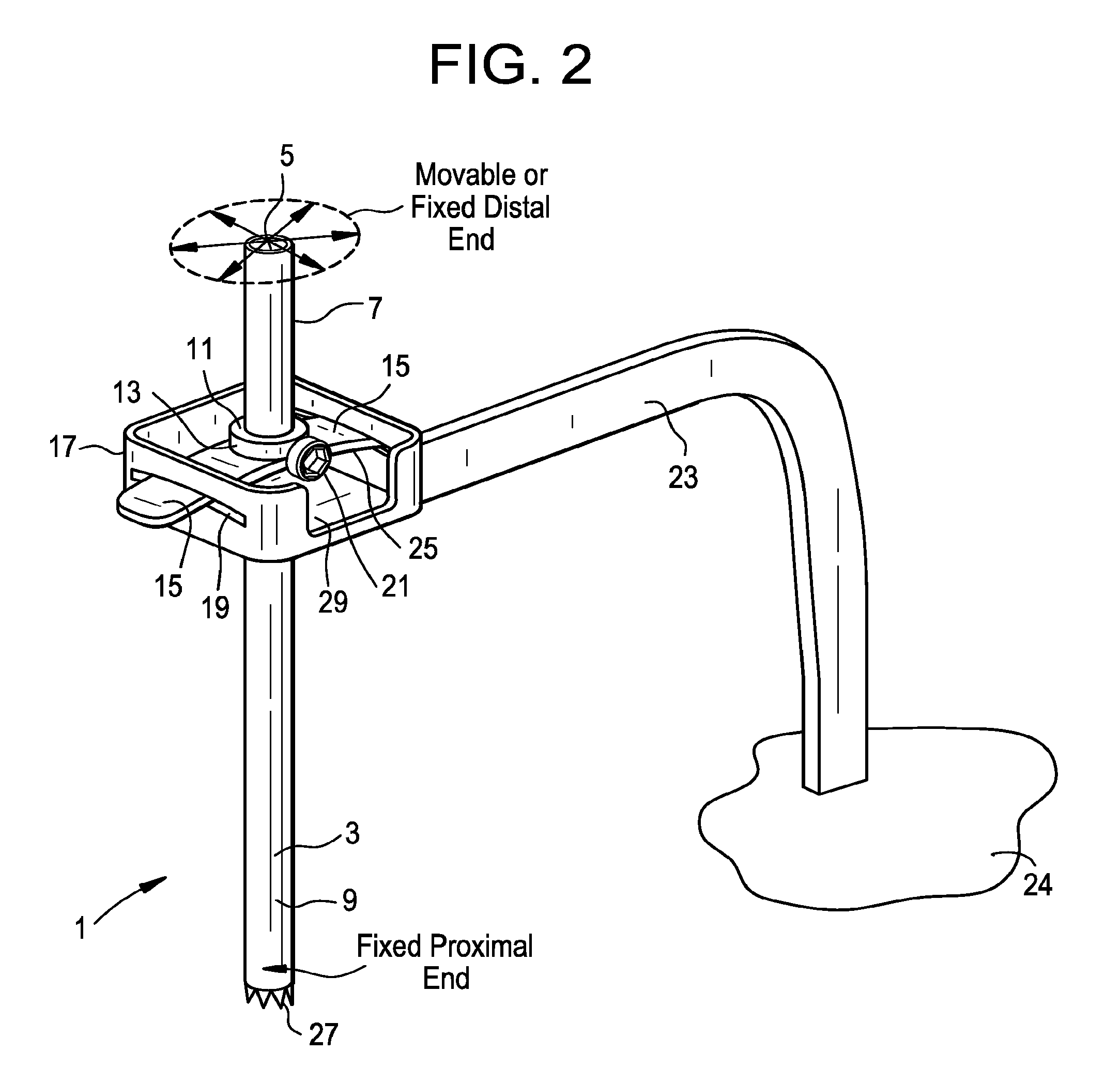
[0051] Now referring to FIG. 2, there is provided a minimally-invasive surgical access system, comprising;
[0052] a) a tube 1 having an outer wall 3, a longitudinal bore 5, a proximal end portion 7 and a distal end portion 9;
[0053] b) a sliding tab 11 comprising a collar 13 having a pair of opposed flanges 15 extending therefrom, wherein the collar is slidable along the outer wall of the tube; and
[0054] c) an annular frame 17 having a pair of substantially opposed slots 19, wherein the flanges of the collar respectively extend through the slots of the annular frame, and wherein the tube extends through the annular frame.
[0055] The embodiment shown in FIG. 2 includes an annular frame that can be fixed onto a stationary unit, such as the operating table, so as to anchor the system. As previously described, the distal end portion of the tube can be fixed onto the bony structures (such as a vertebral body) or soft tissues (such as disc cartilage) within the lumbar spine. When the tube is so distally anchored, the proximal end portion of the tube can move in a substantially conical volume, with the distal end of the tube being its apex. The fixed-in-space annular frame of the embodiment of FIG. 2 limits the range of the motion of the proximal end portion of the tube. The sliding tab component of the system is comprised of a collar with a pair of opposed flanges extending therefrom. Preferably, the shape of the flanges describes a portion of a spherical surface that mimics the limited motion of the tube. The outer annular frame has a pair of opposed matching slots that slidably receive their respective flanges. Preferably, each slot is shaped as an arc that matches the arc-like transverse cross-section of the flange it receives. The working channel is mounted and fixed onto the sliding tab using a set screw 21 that is received in a threaded hole in the collar. The set screw can extend through the collar and contact the outer wall of the tube in the proximal end portion of the tube so as to lock the collar to the tube, thereby preventing the motion of the tube channel in the axial direction. The limits of the lateral motion of the proximal end portion are defined by the outer annular frame. The outer annular frame can be fixed onto the operating table 24 using an extension arm 23.
[0056] Therefore, in preferred embodiments of the first embodiment of the present invention, the system further comprises an arm extending from a stationary unit, wherein the arm is attached to the annular frame. Preferably, the collar comprises a threaded hole, and the system further comprises a set screw received in the threaded hole of the collar. Preferably, the set screw can extend through the collar and contact the outer wall of the tube in the proximal end portion of the tube to lock the collar to the tube. Preferably, each flange comprises a portion of a spherical surface 25 and each slot describes an arc, wherein the flange mates with the slot. Preferably, the distal end portion of the tube has a docking feature (such as a plurality of distally-extending teeth 27) adapted to dock to bone or cartilage. In some embodiments, the collar does not contact the annular frame. In some embodiments, the annular frame has a cutout 29 adapted to allow access by a screwdriver to the collar in order to tighten or loosen the set screw. Preferably, this cutout aligns radially with the set screw. Preferably, the proximal end portion of the tube is able to move in a substantially frustoconical volume when the distal end portion of the tube is fixed. The tube can be a surgical instrument, can be replaced with a surgical instrument, and/or can include a surgical instrument, e.g., inserted therethrough. The surgical instrument can be an endoscope or other visualization instrument. The system need not necessarily provide surgical access, but rather can be used solely for supporting an endoscope or other surgical instrument, or for doing this in combination with other functions.
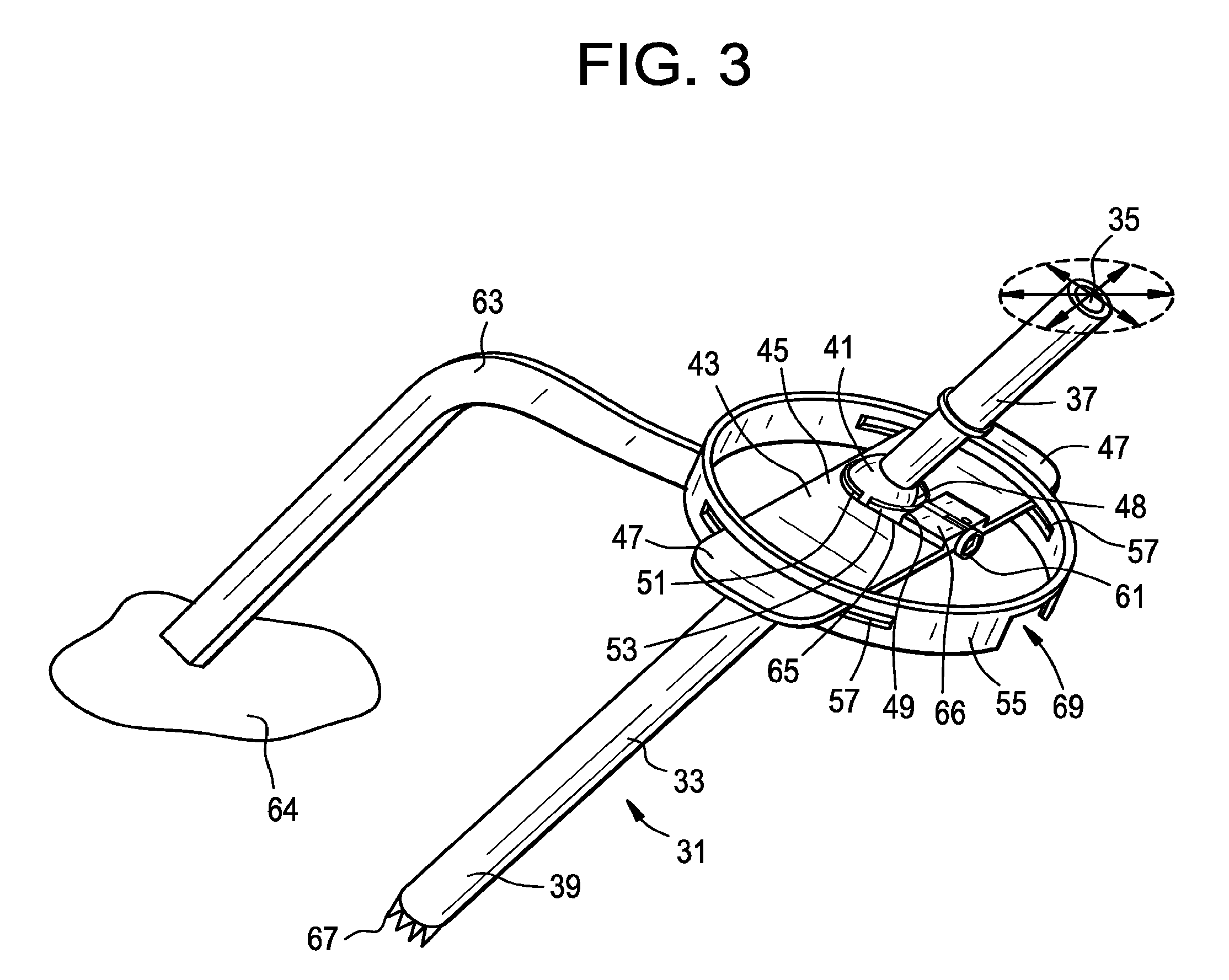
[0057] Now referring to FIG. 3, there is provided a minimally-invasive surgical access system, comprising;
[0058] a) a tube 31 having an outer wall 33, a longitudinal bore 35, a proximal end portion 37, a distal end portion 39, and a substantially spherical element 41 radially surrounding a segment of the outer wall;
[0059] b) a sliding tab 43 having a base 45 and a pair of opposed flanges 47 extending therefrom; the base having a hole 48 therethrough defining a rim 49 having a static portion 51 and a slidable portion 53,
[0060] c) an annular frame 55 having a pair of substantially opposed slots 57, wherein each flange of the sliding tab extends through a respective slot of the annular frame, wherein the tube extends through the annular frame, and wherein the static portion of the rim releasably contacts a first portion of the substantially spherical element and the slidable portion of the rim releasably contacts a second portion of the substantially spherical element.
[0061] The second embodiment of FIG. 3 includes an outer annular frame that could be fixed onto a stationary unit, such as the operating table. As previously described, the distal end portion of the tube can be fixed onto the bony structures or soft tissues of the spine, so that the proximal end portion of the tube can move in a substantially frustoconical volume with the distal tip being the apex. In this particular embodiment, the sliding tab has flat flanges, which are easier to manufacture. Likewise, the outer annular frame has a pair of simple, linear slots to slidably receive the flanges. The sliding tab has an axial hole therein defining a rim, the rim comprising a static hemispherical portion, as well as a movable hemispherical portion. As the working channel passes into the sliding-tab, the set screw 61 can be turned to move the dynamic hemisphere to hold or release the spherical protrusion of the working channel, thereby fixing or release the angel of the sliding tab with respect to the tube. This allows for the movement on the desired range. The whole structure allows for sideways motion of the distal end in a given range (defined by the slot on the outer frame) and blocks the axial motion of the distal end.
[0062] Preferably, in this second embodiment, the system further comprises an arm 63 extending from a stationary unit 64, wherein the arm is attached to the annular frame. Preferably, the base comprises a first cutout 65, and further comprises a sliding door 66 slidably received in the cutout. Preferably, the sliding door comprises the second portion of the rim. Preferably, the sliding door further comprises a substantially hemispherical portion extending from the slidable portion of the rim, wherein the substantially hemispherical portion releasably contacts the second portion of the substantially spherical element to lock the sliding tab to the tube. Preferably, the sliding door is slidably actuated by a set screw. Preferably, each flange of the sliding tab is flat and each respective slot is substantially rectangular, so that the flange mates with the slot. Preferably, the distal end portion of the tube has a docking feature (such as distally extending teeth 67) adapted to dock to bone or cartilage. In some embodiments, the substantially spherical element does not contact the annular frame. Preferably, the annular frame has a second cutout 69 (designed to allow access by a screwdriver) that aligns radially with the set screw. Preferably, the proximal end portion of the tube is able to move in a substantially frustoconical volume when the distal end portion of the tube is fixed. In some embodiments, the flat flanges of the sliding tab are not orthogonal to the tube. The tube can be a surgical instrument, can be replaced with a surgical instrument, and/or can include a surgical instrument, e.g., inserted therethrough. The surgical instrument can be an endoscope or other visualization instrument. The system need not necessarily provide surgical access, but rather can be used solely for supporting an endoscope or other surgical instrument, or for doing this in combination with other functions.
[0063] Now referring to FIGS. 4A-4B, there is provided a minimally invasive surgical access system, comprising;
[0064] a) an upper cap 71 describing a first portion 73 of a substantially spherical surface,
[0065] b) an middle cap 75 describing a second portion 77 of the substantially spherical surface and having a central hole 79,
[0066] c) a lower cap 81 describing a third portion 83 of the substantially spherical surface,
[0067] d) a tube 85 having an outer wall 87 having an attachment portion 89, a longitudinal bore 91, a proximal end portion 93, a distal end portion 95, wherein the upper cap and the lower cap are attached to and radially extend from the outer wall of the tube, wherein at least one of the upper cap and the lower cap is removably attached to the outer wall of the tube, wherein the tube is received in the central hole of the middle cap, and wherein the middle cap is received between the upper cap and the lower cap.
[0068] This concept comprises three spherical caps on top of each other. The middle cap is the proximal point where the rigid arm is fixed. The lower cap extends from the working channel and is preferably integral with the working channel. This lower cap helps to prevent the working channel from being pulled proximally through the hole of the middle cap. The middle cap has a hole of predetermined size that allows for limited lateral motion of the working channel, thereby defining the boundaries of allowed motion. The middle cap is fixed to the operating table via attachments as described above. This middle cap may have a fixation element to help with the fixation. The upper cap has a threaded hole 97 and, when threaded onto the threaded 89 portion of the working channel, helps preventing the channel from advancing distally. In this concept, if the upper cap is advanced distally, it will create friction between the caps and will prevent the motion of the caps relative to each other. In other words, this concept allows for the motion of the working channel and at the same time allows for complete fixation of the distal and proximal ends of the working channel at desired direction.
[0069] Preferably, in the embodiment of FIG. 4, the upper cap is located proximal to the lower cap. Preferably, the middle cap has a fixation element 101 for fixation to a stationary unit. Preferably, the system further comprises an arm 103 extending from a stationary unit 105, wherein the arm is attached to the fixation element. Preferably, the proximal portion of the tube is able to move in a substantially frustoconical volume when the distal end portion of the tube is fixed. Preferably, the distal end portion of the tube has a docking feature 107 adapted to dock to bone. Preferably, the upper cap, middle cap, and lower cap are located in a proximal-most quarter PQ of the tube.
[0070] In some embodiments, the upper cap has a threaded hole 97, the outer wall of the working channel has a threaded portion 89, and wherein the upper cap is threadably received on the threaded portion of the outer wall of the tube.
[0071] In FIG. 4, the upper cap is shown to be removable by virtue of its threadability upon the outer wall of the tube. However, removability is not restricted to threaded features. For example, in some embodiments, the tube and cap may provide a Morse taper lock. In other embodiments, the cap is made of an elastic material that snugly fits the outer wall of the tube.
[0072] In some embodiments, one of the upper cap and the lower cap is removably attached to the outer wall of the tube, and the other is integrally attached to the outer wall of the tube.
[0073] In some embodiments, one of the upper or lower cap has a threaded hole, the outer wall has a threaded portion, and the cap having the threaded hole is threadably received on the threaded portion of the outer wall of the tube.
[0074] In some embodiments, both of the upper cap and the lower cap are removably attached to the outer wall of the tube, preferably threadably attached.
[0075] A functional prototype of this method is shown in FIGS. 5A-C, with different steps of mounting and securing. In FIG. 5A, a tube having an upper threaded portion and a lower cap permanently attached thereto is provided. In FIG. 5B, the middle cap is lowered onto the lower cap. In FIG. 5C, an upper cap with a threaded hole is placed over the middle cap and threaded onto the threaded portion of the tube, thereby trapping the middle cap between the upper and lower caps. Lastly, the middle cap is affixed to a stationary unit.
[0076] In some embodiments, the features of the upper and lower caps are reversed. Therefore, in accordance with the present invention, one of the upper cap and the lower cap is removably attached to the outer wall of the tube, and the other of the caps is integrally attached to the outer wall of the tube. Alternatively, both of the upper cap and the lower cap are removably attached to the outer wall of the tube.
[0077] The tube can be a surgical instrument, can be replaced with a surgical instrument, and/or can include a surgical instrument, e.g., inserted therethrough. The surgical instrument can be an endoscope or other visualization instrument. The system need not necessarily provide surgical access, but rather can be used solely for supporting an endoscope or other surgical instrument, or for doing this in combination with other functions.
[0078] It is believed that the above-described embodiments are generally suitable for use in typical percutaneous spinal surgeries, in conjunction with working channel diameters of only a few millimeters. However, there are certain spinal surgeries in which use of the above embodiments could require very large and bulky constructs. These certain surgeries (which include direct decompression surgeries performed through a mini-open posterior or para-medial approach) often require:
[0079] a) the tube of the working channel diameter to be larger-than-usual (e.g., from about 10 mm to about 30 mm in diameter), or
[0080] b) larger cranial-caudal and medial-lateral tilt angles, so that a larger angular range of motion is realized.
[0081] Therefore, in an effort to address these situations, in a fourth embodiment, and now referring to FIGS. 6A-6O, there is provided an apparatus comprising:
[0082] a) an arm 1 having a proximal end portion 3 connected to a stationary object and a distal end portion 5,
[0083] b) a medial-lateral bar 7 connected to the distal end portion of the arm and having a first rail 9;
[0084] c) a cranial-caudal bar 11 having:
[0085] i) a first rail 13 in slidable engagement with the first rail of the medial-lateral bar in a first direction and
[0086] ii) a second rail 15 extending substantially perpendicularly from the first rail of the cranial-caudal bar;
[0087] d) a working channel construct 17 comprising:
[0088] i) a tube 19 having an outer surface 20 and a proximal end portion 22, and
[0089] ii) a slider 21 attached to the outer surface of the tube and having a first rail 23 in slidable engagement with the second rail of the cranial-caudal bar.
[0090] This fourth embodiment functions substantially similarly to the previously-described embodiments. For example, its working channel tube has a restricted range of motion in the axial direction. Secondly, the fourth embodiment also allows for angular movement of the proximal end of the working channel construct, so as to always leave the tube's tip in the same position. See, for example, FIGS. 6D-6G.
[0091] This fourth embodiment is especially suitable in direct decompression surgeries when a) the tube of the working channel diameter needs to be from about 10 mm to about 30 mm in diameter, or b) larger cranial-caudal and medial-lateral tilt angles are needed, so that a larger angular range of motion is needed.
[0092] In FIG. 6A-6B of the present invention, during the surgery, the working channel tube may be attached to and detached from a slider. Various coupling or push-button mechanisms can be selected for this attachment.
[0093] In FIGS. 6A-6O, the slider is slidably connected to the cranial-caudal bar by mating rails. Preferably, the mating rails of the slider and cranial-caudal bar have mating arcuate shapes. See FIGS. 6D-6E. Preferably, the curvature of these arcuate rails is selected so that the common radius defined by their curves corresponds to the distance between the curve location and the tip of the working channel tube in the final assembly. In other words, the distal tip of the working channel tube defines the centerpoint of the circle described by the mating rails. In this way, it is insured that when the position of the slider along the rail of the cranial-caudal bar is changed in space, the location in space of the centerpoint tube distal end does not change, only the direction of the working channel tube central axis changes. Typically, the curved slider rail can smoothly glide along its mating curved rail of the cranial-caudal bar (thereby continuously changing the cranial-caudal angle of the working channel construct). However, in some embodiments, the relative positions of these rails against each other can be fixed. Various mechanisms can be selected to fix a relative position of these rails. For example, opposing teeth can be provided along each of the mating rails, as in FIG. 6A. These teeth can act as anchors when a fixation is desired. This fixation defines the cranial-caudal angle of the working channel tube.
[0094] In FIGS. 6A-6O, the first and second rails of the cranial-caudal bar are each arcuate. Preferably, the arcs of these rails are equal, so that the cranial-caudal bar defines a spherical surface. The center of the sphere is defined by the tip location of the working channel construct in the final assembly. The rail of the medial-lateral bar mates with the first rail of the cranial-caudal bar and so also preferably has an arcuate shape of the same radius. The two bar components are slidably connected to each other by these arcuate rails. A bolt-slot connection or similar construct can be used to slidably connect the two bars in order to assure that the cranial-caudal bar not only keeps its perpendicular orientation relative to the medial-lateral bar, but is also able to slide along the slot. The position of the cranial-caudal bar relative to the medial-lateral bar defines the medial-lateral angle of the working channel construct. The position can be fixed if desired. Various mechanisms can be considered to realize the position of fixation. For example, teeth can be provided along each rail that act as anchors.
[0095] In FIG. 6C, the medial-lateral bar is attached to a rigid arm, whose position can be fixed relative to the operating room table during the surgery.
[0096] Although the cranial-caudal bar is shown in FIG. 6A as having four rails forming a rectangle with an internal window, in some embodiments, the cranial-caudal bar could potentially consist of 3 rails (defining a "U"-Shape) or 2 rails (defining an "L-" shape). Although the described "4-rail" configuration likely provides for the highest stability of these embodiments against bending of the working channel construct around the axis along the bar, and can provide for the finest dimensions of the rails at the same time, an very stiff sliding/connection mechanism that only needs support from one rail, or without the stabilization of the closing-rod, can also be considered as well.
[0097] In some embodiments (as in FIG. 6B), the cranial-caudal bar has a release button 25 for releasable attachment to the medial-lateral bar. Typically, pressing this button releases the engagement of a teeth-like element on the cranial-caudal bar within the tee engages the teeth of the rail of the medial-lateral bar.
[0098] In some embodiments (as in FIG. 6B), the slider has a release button 27 for releasable attachment to the cranial-caudal bar. Typically, this button engages the teeth of the second rail of the cranial-caudal bar.
[0099] In some embodiments (as in FIG. 6A), the medial-lateral bar has a first window 29 or slot therein for slidable reception of the cranial-caudal bar. Typically, the slot is adjacent the rail of the medial-lateral bar, and the first rail of the cranial-caudal bar has a bolt-like shape so as to provide a slidable bolt-slot connection with the medial-lateral bar.
[0100] In some embodiments (as in FIG. 6A), the cranial-caudal bar has a third rail 31 extending from the first rail of the cranial-caudal bar in a direction substantially parallel to the second rail of the cranial-caudal bar. This embodiment can provide a cranial-caudal bar having a U-shape. In this embodiment, stops can be provided at the two ends of the U-shape so that the slider remains within the pocket of the U-shape.
[0101] In some embodiments, the slider further comprises iii) a second rail (not shown) substantially parallel to the first rail of the slider, wherein the second rail of the slider is in slidable engagement with the third rail of the cranial-caudal bar.
[0102] In some embodiments (as in FIG. 6B), the tube is disposed between the second and third rails of the cranial-caudal bar. This allows the forces that act upon the tube to be evenly supported by the pair of rails of the cranial-caudal bar.
[0103] In some embodiments (as in FIG. 6A), a fourth rail (connecting bar) 35 connects the second and third rails of the cranial-caudal bar to form a second window 37, and the tube extends through the second window. This ensures that the slider will remain slidably attached to the cranial-caudal bar.
[0104] In some embodiments (as in FIG. 6B), the first rail of the medial-lateral bar and the first rail of the cranial-caudal bar have mating teeth 39 thereon, and the second rail of the cranial-caudal bar and the first rail of the working channel construct have mating teeth 41 thereon. With the help of a member that is integrated to the component that is sliding along the rail with the teeth, and that can engage the teeth, this allows the relative positions of the components to be fixed, thereby insuring the location of the working channel tube relative to the patient.
[0105] In some embodiments, a medical device is located within the tube. In some embodiments, thereof, the medical device is an instrument, while in others the medical device is an implant. Typically, the medical device is passed from the proximal end portion of the tube to the distal end portion of the working tube.
[0106] In some embodiments, the first rail of the medial-lateral bar and the first rail of the cranial-caudal bar have matching arcuate shapes. This allows the tube to be tilted with respect to the patient in a first plane while maintaining the location of the distal end of the tube.
[0107] In some embodiments, the second rail of the cranial-caudal bar and the first rail of the slider have matching arcuate shapes. This allows the tube to be tilted with respect to the patient in a second plane while maintaining the location of the distal end of the tube.
[0108] In some embodiments, the slider is attachable and detachable from/to the outer surface of the tube at the proximal end portion of the tube. This allows a fine control of the location of the proximal end portion of the tube. This allows as well that the tube can be introduced into the patient at the right location in a first step of a surgery. The rest of the components are pre-assembled and can be attached to the tube at this attachment location of the slider, while the arm is in a flexible configuration. After attaching the tube to the rest of the assembly, the arm can be brought to a rigid configuration, leaving only the option of changing the position of the tube, with respect to the patient to the angular changes by the rail connections.
[0109] In some embodiments, the first rail of the cranial-caudal is in slidable engagement with the first rail of the medial-lateral bar by virtue of a bolt-slot connection. This arrangement helps maintain the orientation of the cranial-caudal bar vis-a-vis the medial-lateral bar. FIGS. 6K-6L disclose views of the fourth embodiment apparatus wherein the medial-lateral bar runs parallel to the spine.
[0110] The tube can be a surgical instrument, can be replaced with a surgical instrument, and/or can include a surgical instrument, e.g., inserted therethrough. The surgical instrument can be an endoscope or other visualization instrument. The system need not necessarily provide surgical access, but rather can be used solely for supporting an endoscope or other surgical instrument, or for doing this in combination with other functions.
[0111] For example, FIG. 7 illustrates an exemplary embodiment in which the tube is replaced with an endoscope 59. The endoscope can be flexible or rigid. The endoscope can include any one or more of a lens, a light source, a camera, an eyepiece, and a working channel. The endoscope can be cystoscope, nephroscope, bronchoscope, arthroscope, colonoscope, and/or laparoscope. The endoscope can be used to visualize a surgical site within a patient's body, such as the spine, abdomen, pelvis, joints, GI system, colon, bladder, kidney, throat, ear, cranium, or the like.
[0112] The components of the present invention are preferably made from a biocompatible metal such as stainless steel, titanium alloy or cobalt-chrome. However, it is contemplated that the components can be made from polymeric materials so as to provide an inexpensive, single use system.
* * * * *
D00000
D00001
D00002
D00003
D00004
D00005
D00006
D00007
D00008
D00009
D00010
D00011
D00012
D00013
D00014
D00015
D00016
D00017
D00018
D00019
D00020

D00021
XML
uspto.report is an independent third-party trademark research tool that is not affiliated, endorsed, or sponsored by the United States Patent and Trademark Office (USPTO) or any other governmental organization. The information provided by uspto.report is based on publicly available data at the time of writing and is intended for informational purposes only.
While we strive to provide accurate and up-to-date information, we do not guarantee the accuracy, completeness, reliability, or suitability of the information displayed on this site. The use of this site is at your own risk. Any reliance you place on such information is therefore strictly at your own risk.
All official trademark data, including owner information, should be verified by visiting the official USPTO website at www.uspto.gov. This site is not intended to replace professional legal advice and should not be used as a substitute for consulting with a legal professional who is knowledgeable about trademark law.