Extension Tube For Electric Vacuum Cleaner
OKA; YASUHIRO ; et al.
U.S. patent application number 16/325695 was filed with the patent office on 2019-07-11 for extension tube for electric vacuum cleaner. The applicant listed for this patent is SHARP KABUSHIKI KAISHA. Invention is credited to YUHJI OHNISHI, YASUHIRO OKA.
| Application Number | 20190208974 16/325695 |
| Document ID | / |
| Family ID | 62110553 |
| Filed Date | 2019-07-11 |


View All Diagrams
| United States Patent Application | 20190208974 |
| Kind Code | A1 |
| OKA; YASUHIRO ; et al. | July 11, 2019 |
EXTENSION TUBE FOR ELECTRIC VACUUM CLEANER
Abstract
The purpose of the present invention is to provide an extension tube for electric vacuum cleaner, which has a reduced weight, is easier to grip, and is easier to operate. This extension tube for electric vacuum cleaner comprises a tube body and a conductive unit provided so as to pass through the interior of the tube body. The conductive unit has a conductive cable and a hollow plate which accommodates the conductive cable.
| Inventors: | OKA; YASUHIRO; (Sakai City, JP) ; OHNISHI; YUHJI; (Sakai City, JP) | ||||||||||
| Applicant: |
|
||||||||||
|---|---|---|---|---|---|---|---|---|---|---|---|
| Family ID: | 62110553 | ||||||||||
| Appl. No.: | 16/325695 | ||||||||||
| Filed: | February 8, 2017 | ||||||||||
| PCT Filed: | February 8, 2017 | ||||||||||
| PCT NO: | PCT/JP2017/004585 | ||||||||||
| 371 Date: | February 14, 2019 |
| Current U.S. Class: | 1/1 |
| Current CPC Class: | A47L 9/246 20130101; A47L 9/244 20130101; A47L 9/322 20130101; A47L 9/248 20130101; A47L 9/2857 20130101; A47L 9/24 20130101; A47L 9/122 20130101; A47L 5/26 20130101; A47L 9/1666 20130101 |
| International Class: | A47L 9/24 20060101 A47L009/24 |
Foreign Application Data
| Date | Code | Application Number |
|---|---|---|
| Nov 9, 2016 | JP | 2016-219072 |
Claims
1. An extension tube for an electric vacuum cleaner comprising: a tube body; and a conductive unit provided so as to pass through the tube body, wherein the conductive unit includes conductive cables and a hollow plate accommodating the conductive cables.
2. The extension tube according to claim 1, wherein the hollow plate has a support plate and a cover plate, the support and cover plates covering the conductive cable so as to hold the conductive cable therebetween.
3. The extension tube according to claim 2, wherein the conductive cable and the support plate are longer than the tube body, the conductive cable is longer than the support plate, and the support plate is longer than the cover plate.
4. The extension tube according to claim 2, wherein the support plate includes a base part having a recessed cross-section and a pair of hook pieces provided along upper ends of both lateral surfaces of the base part.
5. he extension tube according to claim 4, wherein the support plate has, on the base part, a flat bottom part for receiving the cover plate, and the cover plate has an outer face having an arc cross-section.
6. The extension tube according to claim 2, wherein the cover plate has a groove provided along a longitudinal direction in a widthwise central part for individually housing the conductive cables.
7. The extension tube according to claim 6, wherein the cover plate has hemisphere ribs at both ends and an intermediate part of the groove, the hemisphere ribs holding the conductive cables housed in the groove to prevent displacement of the conductive cables.
Description
TECHNICAL Field
[0001] The present invention relates to an extension tube for an electric vacuum cleaner.
BACKGROUND ART
[0002] To take an example of a traditional extension tube for an electric vacuum cleaner, Patent Literature 1 suggests an extension tube comprising a tube body; a cover attached to an outer surface of the tube body and extending in a longitudinal direction; an insulating resin plate provided at a space between the tube body and the cover; and lead wires placed on and supported by the insulating resin plate, wherein both ends of each lead wire are exposed to the outside so as to be electrically connectable with terminals of a vacuum cleaner body and of an intake port body.
CITATION LIST
Patent Literature
[PTL 1]
Japanese Unexamined Patent Application Publication No. 2012-249699
SUMMARY OF INVENTION
Technical Problem
[0003] The extension tube described in Patent Literature 1 becomes thick because of comprising the insulating resin plate; the lead wires; and the cover, each of which being placed on an outer surface of the tube body and extending along a longitudinal direction, resulting in an increase in a total weight of the extension tube in addition to impairing ease of gripping the extension tube; therefore, there arises a problem that operability of the extension tube decreases at a time when determining a direction of the intake port body with use of the extension tube.
[0004] In view of such a problem above, the present invention has an object of providing an extension tube for an electric vacuum cleaner having a reduced weight and being easier to be gripped in addition to being easier to be operated.
Solutions to Problem
[0005] The present invention provides an extension tube for an electric vacuum cleaner, the extension tube comprising a tube body and a conductive unit provided so as to be laid in the tube body, [0006] wherein the conductive unit includes conductive cables and a hollow plate that contains the conductive cables.
[0007] The extension tube according to the present invention is applicable to, for example, an electric vacuum cleaner in which an intake port body having a motor-driven rotary brush incorporated therein is connected to a vacuum cleaner body and which supplies electric power to the motor from the vacuum cleaner body via the extension tube to clean a floor surface while rotating the rotary brush in the intake port body. In addition, in this extension tube, the conductive unit is compactly provided inside the tube body, and the tube body is not so thick. Therefore, the extension tube has reduced weight and is easier to be gripped, which leads to improved operability when a user changes the direction of movement of the intake port body via the extension tube. BRIEF DESCRIPTION OF DRAWINGS
[0008] FIG. 1 illustrates a left-side view of an electric vacuum cleaner in accordance with Embodiment 1 of the present invention.
[0009] FIG. 2 illustrates a perspective view of the vacuum cleaner body of the electric vacuum cleaner in accordance with Embodiment 1.
[0010] FIG. 3 illustrates a left-side cross-section view of an inner structure of an operating portion in a handle of the vacuum cleaner body of FIG. 2.
[0011] FIG. 4 illustrates a left-side cross-section view of an inner structure of the vacuum cleaner body of FIG. 2.
[0012] FIG. 5 illustrates a perspective view of a disassembled housing of a drive unit of the vacuum cleaner body of FIG. 2.
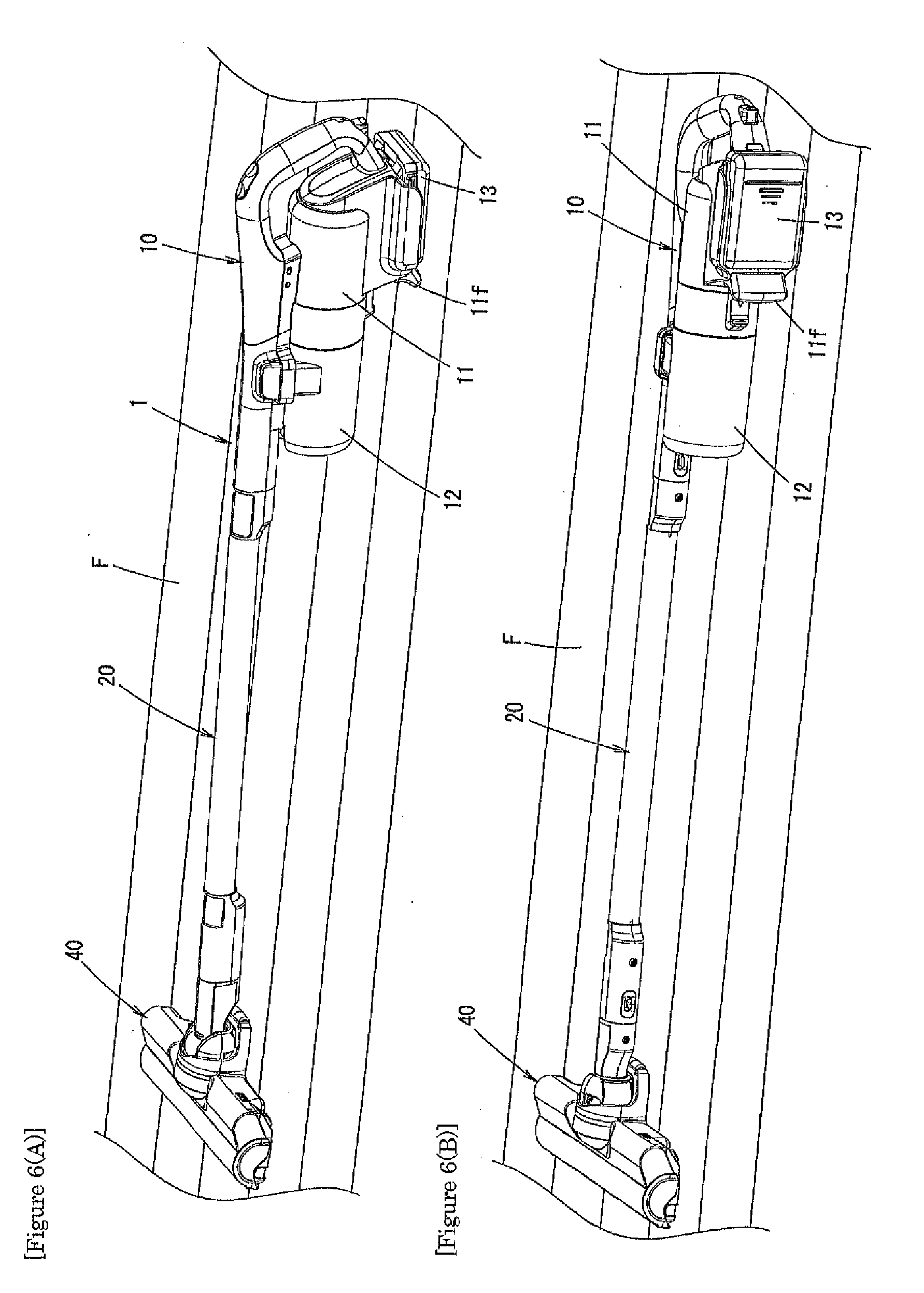
[0013] FIG. 6(A) illustrates the electric vacuum cleaner in accordance with Embodiment 1 that is placed on a floor; and FIG. 6(B) illustrates the electric vacuum cleaner in accordance with Embodiment 1 that lies on a floor.
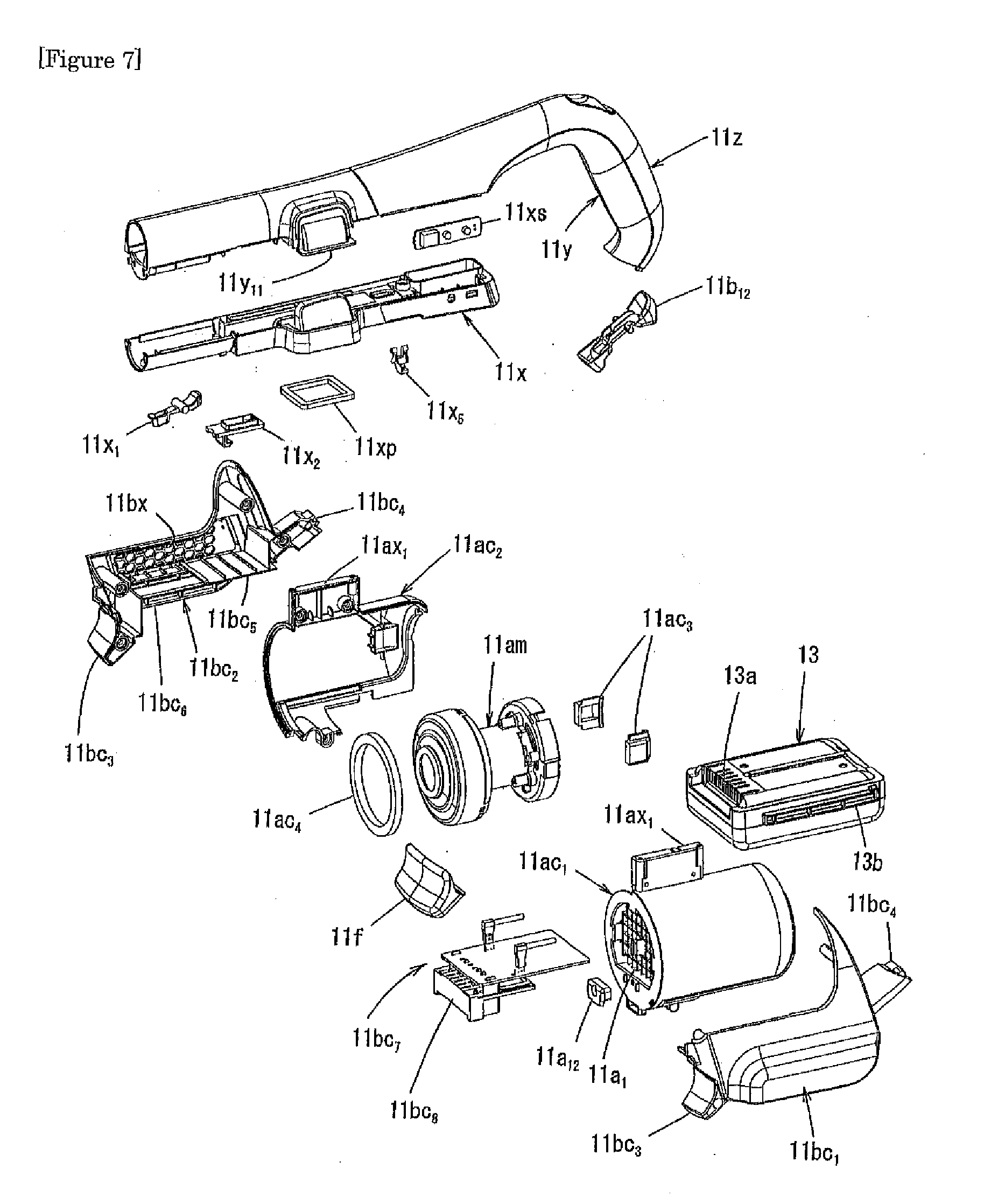
[0014] FIG. 7 illustrates an exploded view of the drive unit of the electric vacuum cleaner in accordance with Embodiment 1.
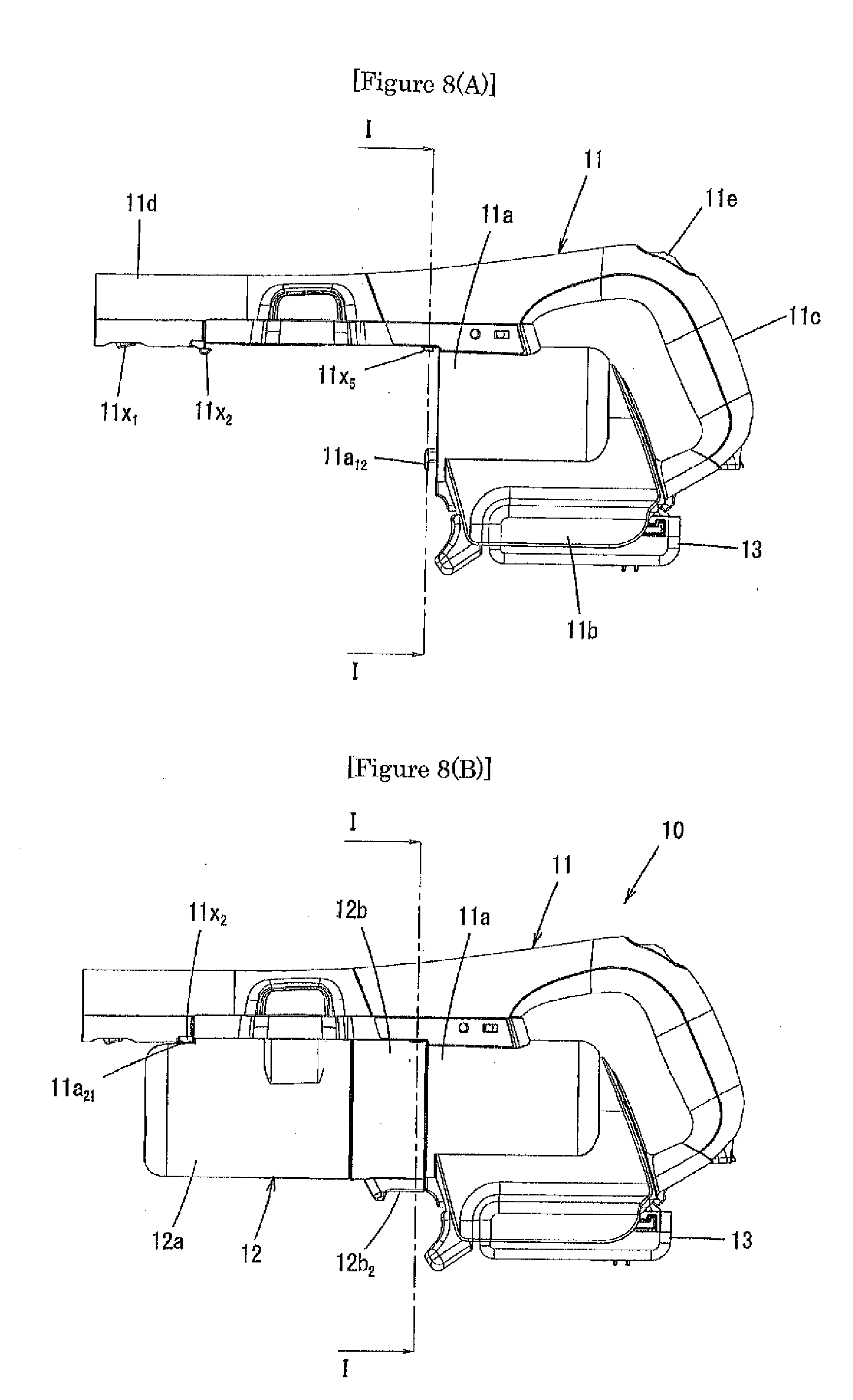
[0015] FIG. 8(A) illustrates a left-side view of the drive unit; and FIG. 8(B) illustrates a left-side view of the vacuum cleaner body.
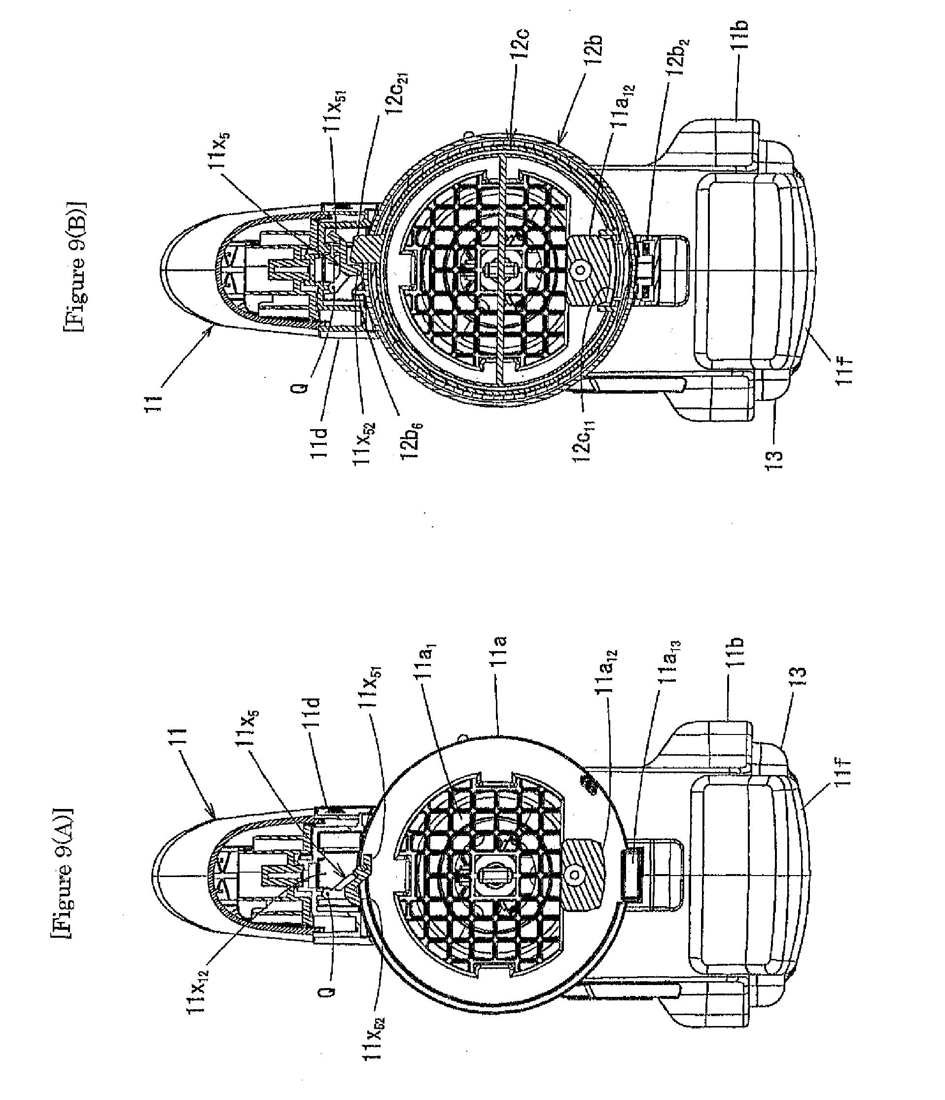
[0016] FIG. 9(A) illustrates a cross-section view taken from line I-I of Fig. A(A); and FIG. 9(B) illustrates a cross-section view taken from line I-I of Fig. A(B).
[0017] FIG. 10(A) illustrates a perspective view of a dust cup to be installed in the electric vacuum cleaner in accordance with Embodiment 1; and FIG. 10(B) illustrates an exploded view of the dust cup.
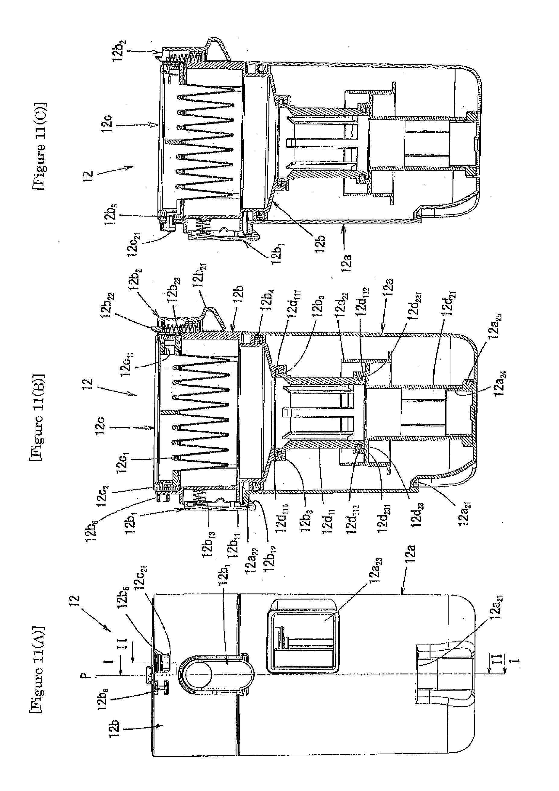
[0018] FIG. 11(A) illustrates a front view of the dust cup to be installed in the electric vacuum cleaner in accordance with Embodiment 1; FIG. 11(B) illustrates a cross-section view taken from line I-I of FIG. 11(A); and FIG. 11(C) illustrates a cross-section view taken from line II-II of FIG. 11(A).
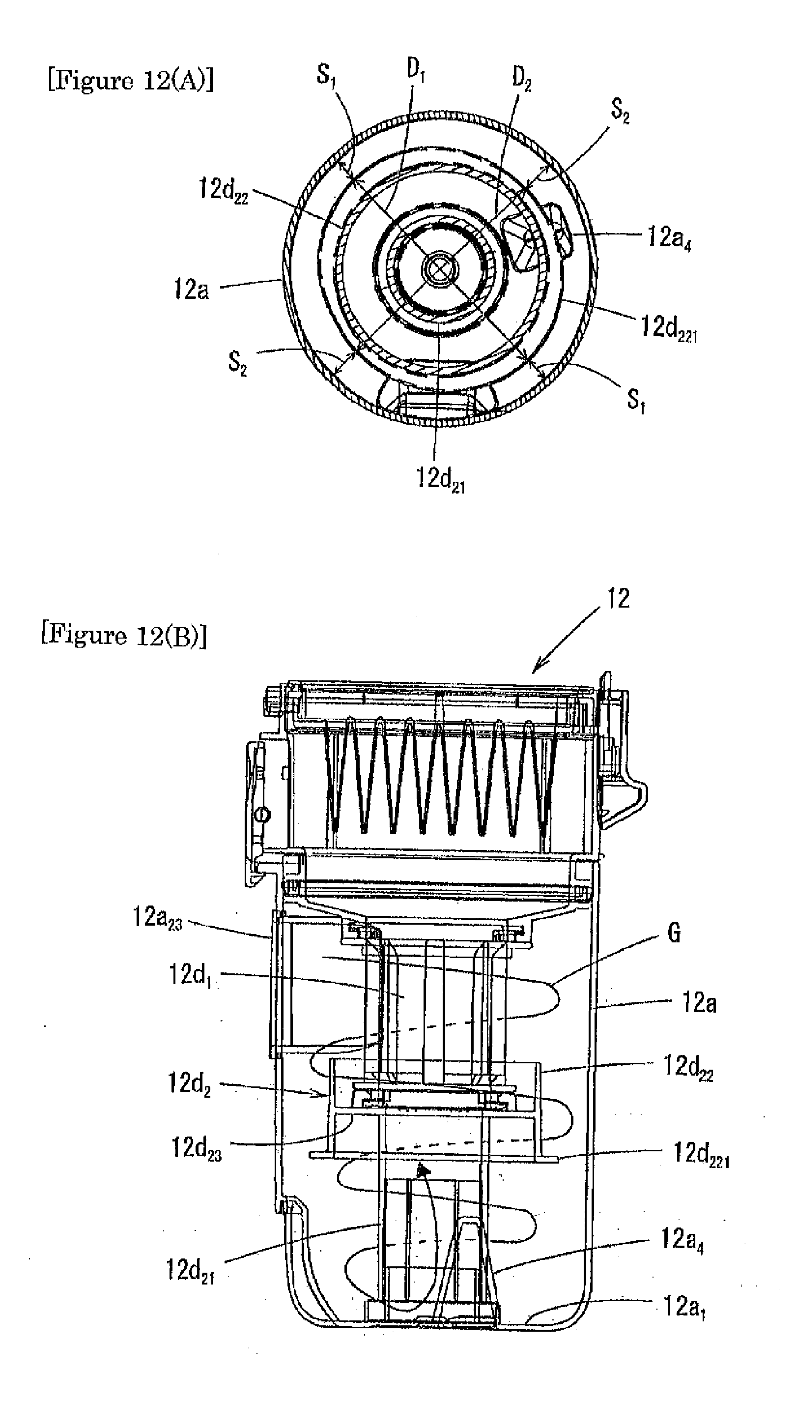
[0019] FIG. 12(A) illustrates a plan cross-section view of a lower part of a dust cup unit; and FIG. 12(B) illustrates a side cross-section view of the dust cup unit.
[0020] FIG. 13(A) illustrates a front view of an extension tube of the electric vacuum cleaner in accordance with Embodiment 1; FIG. 13(B) illustrates a side view of the extension tube; and FIG. 13(C) illustrates a cross-section view taken from line I-I of FIG. 13(A).
[0021] FIG. 14 illustrates an exploded view of the extension tube of FIG. 13(A).
[0022] FIG. 15 illustrates an explanatory view of an inner structure of a first connecting pipe unit and a second connecting pipe unit of the extension tube of FIG. 13(A) which are viewed from the front side.
[0023] FIG. 16 illustrates a transverse cross-section view of the tube body of the extension tube of FIG. 13(A).
[0024] FIG. 17 illustrates an explanatory view of a layered structure of the tube body of the extension tube of FIG. 13(A).
[0025] FIG. 18(A) illustrates a front view of a conductive unit in the extension tube of FIG. 13(A); FIG. 18(B) illustrates a side view of the conductive unit; and FIG. 18(C) illustrates a rear view of the conductive unit.
[0026] FIG. 19 illustrates an exploded view of the conductive unit of FIG. 18(A).
[0027] FIG. 20(A) illustrates a cross-section view taken from line I-I of FIG. 18(A); FIG. 20(B) illustrates a cross-section view taken from line II-II of FIG. 18(A); and FIG. 20(C) illustrates a cross-section view taken from line III-III of FIG. 18(A).
[0028] FIG. 21 illustrates lead wires in a cover plate of the conductive unit of FIG. 18(A).
[0029] FIG. 22 illustrates a transverse cross-section view of the first connecting pipe unit of the extension tube of FIG. 13(A).
[0030] FIG. 23 illustrates a bottom view of an intake port body of the electric vacuum cleaner in accordance with Embodiment 1.
[0031] FIG. 24 illustrates a side view of the intake port body illustrated in FIG. 23.
[0032] FIG. 25 illustrates a cross-section view of the intake port body taken from line I-I of FIG. 23.
[0033] FIG. 26 illustrates a cross-section view of the intake port body taken from line II-II of FIG. 23.
DESCRIPTION OF EMBODIMENTS
Embodiment 1
[0034] FIG. 1 illustrates a left-side view of an electric vacuum cleaner in accordance with Embodiment 1 of the present invention.
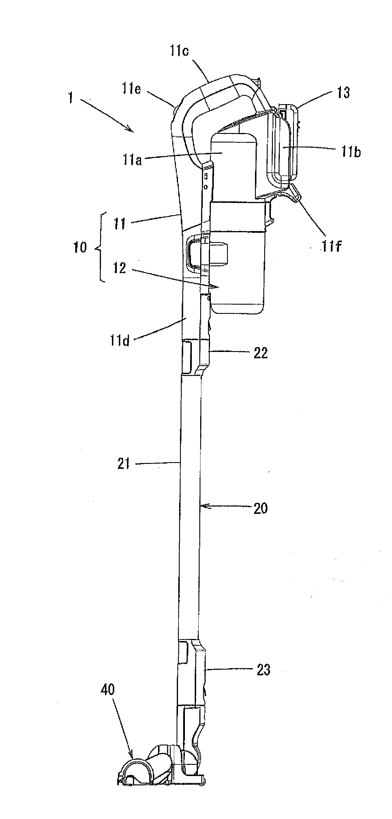
[0035] An electric vacuum cleaner 1 in accordance with Embodiment 1 comprises a vacuum cleaner body 10, an extension tube 20, and an intake port body 40. The extension tube may or may not have a structure that can extend the tube itself. Unlike a handheld vacuum cleaner in which an intake port body is attached directly to the vacuum cleaner body, the vacuum cleaner of the present invention can be used as a stick vacuum cleaner having the extension tube installed between the intake port body and the vacuum cleaner body, and has a long distance from the electric vacuum cleaner body to the intake port body.
Vacuum Cleaner Body
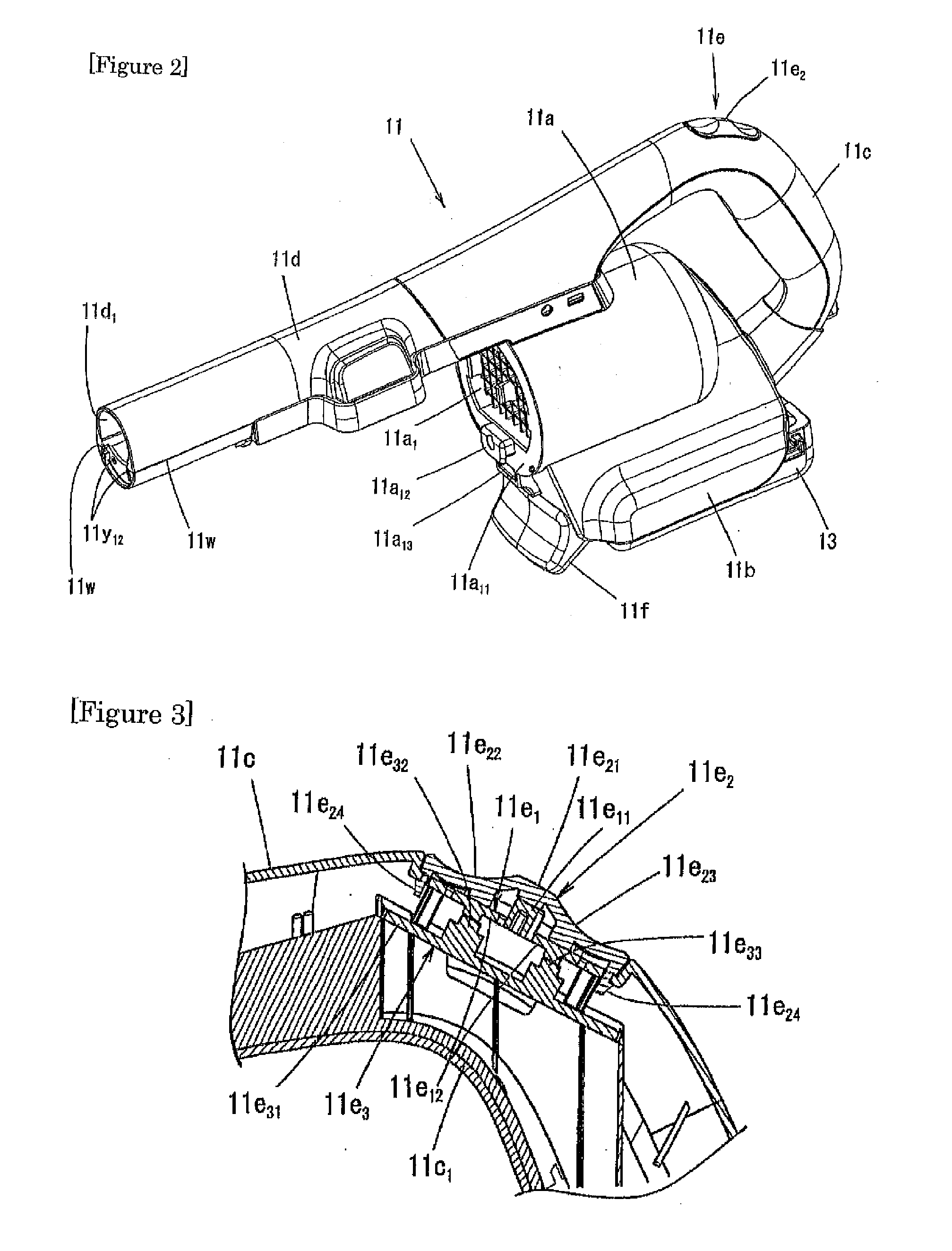
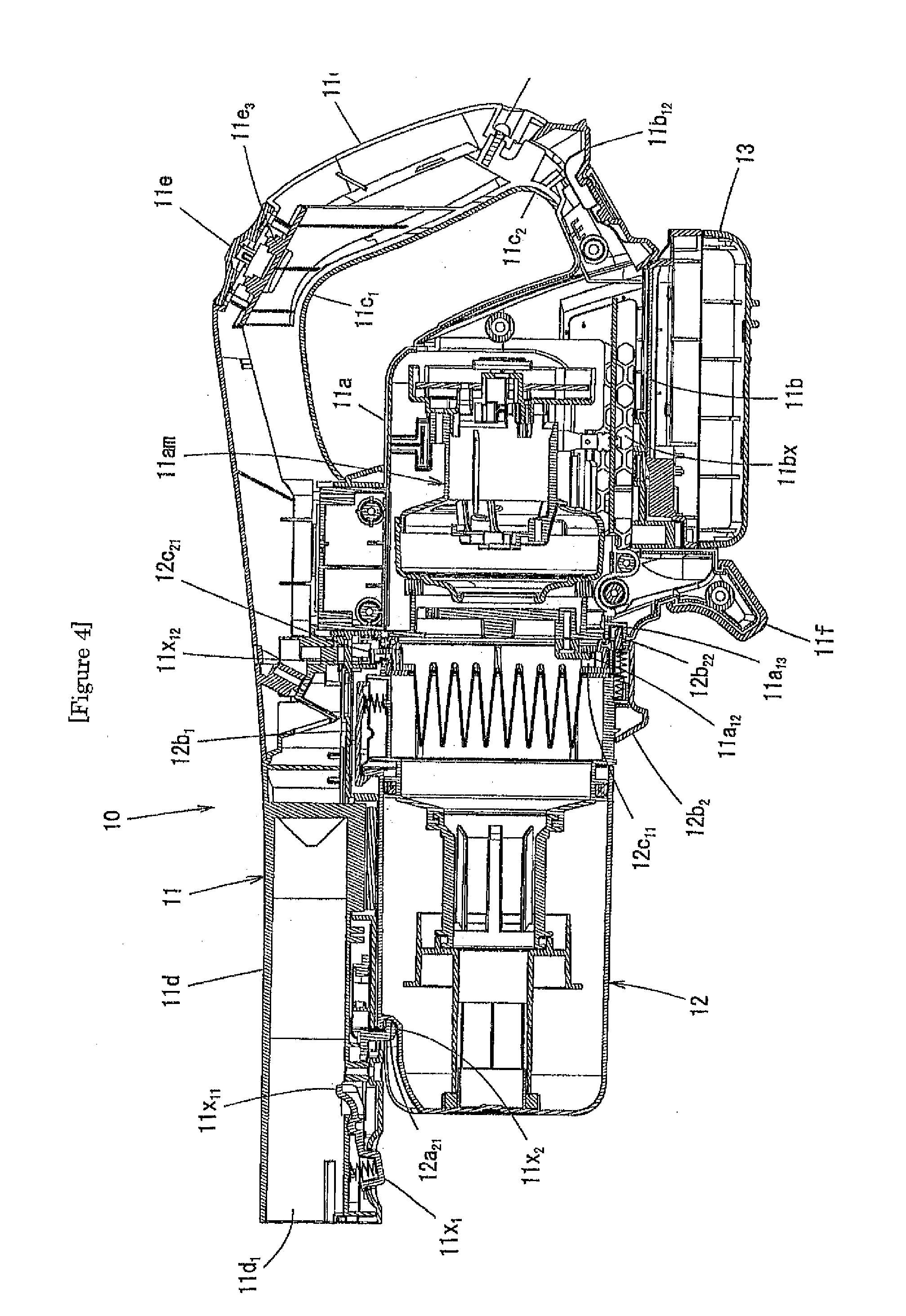
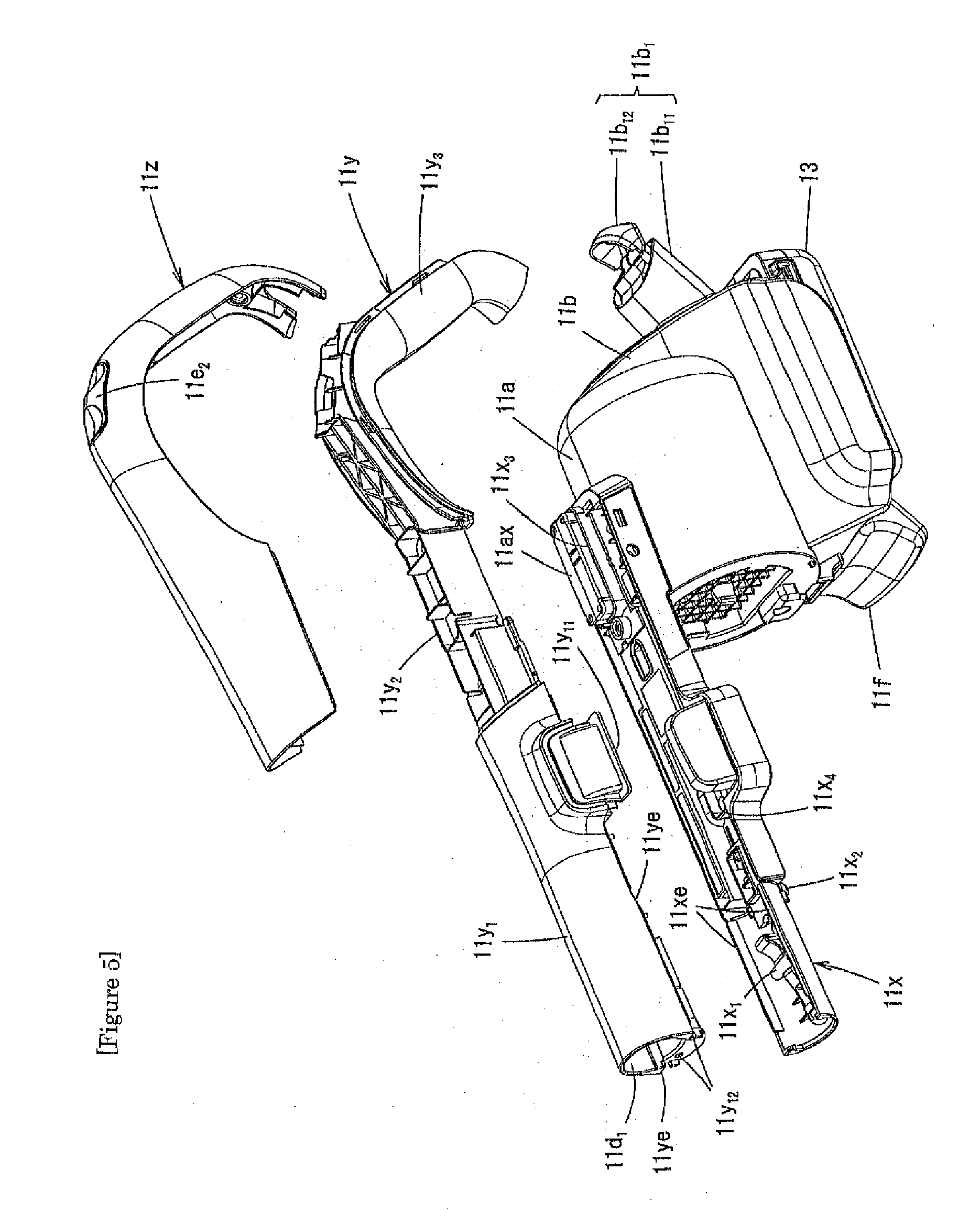
[0036] FIG. 2 illustrates a perspective view of the vacuum cleaner body of the electric vacuum cleaner in accordance with Embodiment 1; and FIG. 3 illustrates a left-side cross-section view of an inner structure of an operating portion in a handle of the vacuum cleaner body of FIG. 2. FIG. 4 illustrates a left-side cross-section view of an inner structure of the vacuum cleaner body of FIG. 2; and FIG. 5 illustrates a perspective view of a disassembled housing of a drive unit of the vacuum cleaner body of FIG. 2. FIG. 6(A) illustrates the electric vacuum cleaner in accordance with Embodiment 1 that is placed on a floor; and FIG. 6(B) illustrates the electric vacuum cleaner in accordance with Embodiment 1 that lies on a floor.
[0037] The vacuum cleaner body 10 comprises a drive unit 11, a dust cup unit 12 detachably attached to the drive unit 11, and a battery 13.
Drive Unit
[0038] As illustrated in FIG. 2, FIG. 4, and FIG. 5, the drive unit 11 has a body 11a containing an electric blower 11am; a battery mounting part 11b communicating with the body 11a; a handle 11c having two ends that communicate with the body 11a and the battery mounting part 11b, respectively; and an intake tube 11d that communicates with a joint part connecting the body 11a to the handle 11c and projects in an opposite direction from the handle 11c.
[0039] The component parts of the drive unit 11 will be described below on the basis of the following specific directions: The intake tube 11d side is regarded as the front side; the handle 11c side is regarded as the rear side; the battery mounting part 11b side is regarded as the bottom side; the opposite side from the battery mounting part 11b is regarded as the upper side; the left side in a state where the handle 11c is positioned frontward is regarded as a left direction; and the right side in this state of the handle is regarded as a right direction.
[0040] The body 11a is configured to have a shell which is a cylindrical housing part having a front opening 11a.sub.1, and this front opening 11a.sub.1 has lattice-shaped ribs.
[0041] The body 11a has a fitting convex portion 11ax placed on its top surface, and the fitting convex portion 11ax has on its top surface an opening that draws lead wires from the body 11a to the outside.
[0042] The body 11a has an inner flange along a fringe of the front opening 11a.sub.1, and a lower part of the inner flange is a wide-width inner flange wide portion 11a.sub.11.
[0043] The inner flange wide portion 11a.sub.11 is provided with the following component parts: a locking convex portion 11a.sub.12 and an engaging concave portion 11a.sub.13 detachably locking to a locking concave portion 12c.sub.11 and an engaging nail 12b.sub.23, respectively, of a second locking mechanical section 12b.sub.2, which is provided to the dust cup unit 12 (which will be described below). The locking convex portion 11a.sub.12 projects toward the bottom side, and the engaging concave portion 11a.sub.13 opens toward the front side.
[0044] The battery mounting part 11b opens toward the bottom side and the rear side, and has a concave portion having terminals in its back that are electrically connectable with terminals of the battery 13; and the battery mounting part is configured to enable the battery 13 to be inserted into its concave portion from its rear side and to be mounted therein and also is configured to enable the battery 13 to be drawn therefrom toward the rear side and to be removed (or detached) from the concave portion. The battery mounting part 11b is configured to have concave channels that extend in a front-rear direction and are placed on a right-left inner side surface of the concave portion. The battery 13 is configured to have convex portions on its right-left side surface so that the convex portions on the both sides can respectively slide and fit into the concave channels on the both sides at a time when the battery 13 is mounted into the battery mounting part 11b.
[0045] The battery mounting part 11b has an exhaust opening 11bx on a right-side surface of a housing of the battery mounting part, and the exhaust opening is to exhaust an air current from the electric blower 11am to the outside (see FIG. 4).
[0046] The handle 11c has an upper curved portion 11c.sub.1 and a lower curved portion 11c.sub.2, both of which roughly having the shape of the letter "U"; and the upper curved portion 11c.sub.1 has an operating portion 11e on its external side.
[0047] As illustrated in FIG. 3 and FIG. 4, the operating portion 11e has the following component parts: a concave portion 11e.sub.1 formed in a plastic housing that constitutes the upper curved portion 11c.sub.1 of the handle 11c; a pad 11e.sub.2 that is made of an elastic material (rubber, elastomer, etc.) and is mounted on the external side of the concave portion 11e.sub.1; and a switch unit 11e.sub.3 provided inside the concave portion 11e.sub.1 (inside the housing).
[0048] The operating portion 11e has a convex rib 11e.sub.11 in a center of the concave portion 11e.sub.1; and the convex rib 11e.sub.11 has a pair of U-shaped slits formed at its front and rear positions; and an inner area of each U-shaped slit is an elastic and deformable blade spring 11e.sub.12. Each blade spring 11e.sub.12 has a convex portion on its lower surface. The U-shaped slits of the concave portion 11e.sub.1 have locking openings formed in front of and the back of the slits, respectively; and a pair of front and rear inserting locking fragments 11e.sub.24 of the pad 11e.sub.2 (which will be described below) are respectively inserted into the locking openings.
[0049] The pad 11e.sub.2 has, on its upper surface side, concave portions 11e.sub.22 and 11e.sub.23 in front of and the back of a center portion 11e.sub.21, respectively. The pad 11e.sub.2 has, on its lower surface side, a convex portion at a corresponding position of the center portion 11e.sub.21 and at a corresponding position of the pair of concave portions 11e.sub.22 and 11e.sub.23; and these convex portions have the inserting locking fragments 11e.sub.24 formed at their front and rear positions, respectively. The center portion 11e.sub.21 comes in contact with the convex rib 11e.sub.11; and the concave portions 11e.sub.22 and 11e.sub.23 placed at the front and at the back come in contact with the blade springs 11e.sub.12, respectively.
[0050] The switch unit 11e.sub.3 in the handle 11c has a circuit board 11e.sub.31 supported and fixed by a rib structure in the upper curved portion 11c.sub.1 and also has a pair of front switch 11e.sub.32 and rear switch 11e.sub.33 provided on the circuit board 11e.sub.31.
[0051] In this operating portion 11e, the circuit board 11e.sub.31 is configured to enable the following operations. For example, power is turned on by pushing the front switch 11e.sub.32 or the rear switch 11e.sub.33. After that, pushing the front switch 11e.sub.32 once turns on a high mode; pushing the front switch twice turns on a standard mode; and pushing the front switch three times or more allows these modes to repeat. The power can be shut down by pushing the rear switch 11e.sub.33 when the power is on.
[0052] When a user operates the operating portion 11e and pushes the front concave portion 11e.sub.22 or the rear concave portion 11e.sub.23 of the pad 11e.sub.2 with his finger, the front switch 11e.sub.32 or the rear switch 11e.sub.33 is pushed by the blade spring 11e.sub.12. If the user squeezes tight on the pad 11e.sub.2 during cleaning, the user's palm would not push in the front concave portion 11e.sub.22 or the rear concave portion 11e.sub.23, and a misoperation unintended by the user is prevented, because the center portion 11e.sub.21 placed between the front concave portion 11e.sub.22 and the rear concave portion 11e.sub.23 of the pad 11e.sub.2 projects and is supported by the convex rib 11e.sub.11.
[0053] As illustrated in FIG. 5, the intake tube 11d and the handle 11e are assembled (or built) with a first member 11x, a second member 11y, and a third member 11z (which will be described below).
[0054] As illustrated in FIG. 4 and FIG. 5, the first member 11x extends in a front-rear direction and has at its front end a concave portion containing a locking member 11x.sub.1, a hooking member 11x.sub.2, etc.; and the first member also has at its rear end a fitting opening 11x.sub.3 into which the fitting convex portion 11ax of the body 11a is fitted.
[0055] The locking member 11x.sub.1 is swingably installed in the first member 11x so as to rotate on a horizontal axis; and in a state where the above-described component parts are assembled, the front end of the locking member 11x functions as a push button that projects downward from an opening formed on the first member 11x to the outside. A rear end of the locking member 11x functions as an engaging nail 11x.sub.11 that detachably engages with an engaging concave portion 22a.sub.31 (see FIGS. 9(A) to 9(C)) of a first connecting pipe unit 22 (to be described below) of the extension tube 20 at a time when the extension tube 20 is inserted into a front opening 11d.sub.1 of the intake tube 11d. In a state where the above-described component parts are assembled, a coil spring is placed between the first member 11x and the second member 11y, and biases downward the front end of the locking member 11x (to the outside).
[0056] The hooking member 11x.sub.2 detachably locks into a locking concave portion 12a.sub.21 (to be described below) of the dust cup unit 12 installed in the vacuum cleaner body 10, and projects downward from the opening formed on the first member 11x to the outside.
[0057] The first member 11x has, on its left-side surface of its middle part in a front-rear direction, a connection port 11x.sub.4 that is connected with an outflow port 11y.sub.11 (to be described below) of the second member 11y; and the first member also has, on its lower surface side of its rear end, a concave portion, where contains a first locking mechanical section 12b.sub.1, and a concave portion 11x.sub.12, into which a positioning convex portion 12c.sub.21 is fitted, (which will be described below) of the dust cup unit 12 installed in the vacuum cleaner body 10.
[0058] The second member 11y has the following component parts: a front tube 11y.sub.1 communicating the front opening 11d.sub.1 with the outflow port 11y.sub.11; an intermediate rib structure portion 11y.sub.2 communicating with the front tube 11y.sub.1; and an inner handle structure portion 11y.sub.3 communicating with the intermediate rib structure portion 11y.sub.2 so as to form an inner part of the handle 11c. The front tube 11y.sub.1 has, at its lower surface side-front end, a pair of female terminals 11y.sub.12 electrically connected with the pair of lead wires (not illustrated), respectively, that is drawn from the body 11a; and the inner handle structure portion 11y.sub.3 contains the switch unit 11e.sub.3 of the operating portion 11e in its curved intermediate portion.
[0059] The third member 11z is to cover the intermediate rib structure portion 11y.sub.2 and the inner handle structure portion 11y.sub.3, and has the pad 11e.sub.2 of the operating portion 11e in its intermediate portion.
[0060] The battery mounting part 11b has at its rear part a junction 11b.sub.1 joining with a rear end of the second member 11y and a rear end of the third member 11z. This junction 11b.sub.1 comprises a fixed projecting portion 11b.sub.11 and a holding member 11b.sub.12 provided swingably on the fixed projecting portion 11b.sub.11. The holding member 11b.sub.12 is operated at a time when the battery 13 is removed (or detached).
[0061] One example of how the first member 11x, the second member 11y, and the third member 11z are assembled is that firstly the fitting opening 11x.sub.3 of the first member 11x is fitted to the fitting convex portion 11ax of the body 11a.
[0062] Secondly the pair of lead wires (not illustrated) drawn from the body 11a is electrically connected with the pair of female terminals 11y.sub.12 of the second member 11y, respectively; then the pair of female terminals 11y.sub.12 is attached to a front end of the second member 11y; and then the second member 11y is placed on the first member 11x. This enables the outflow port 11y.sub.11 of the second member 11y to be connected with the connection port 11x.sub.4 of the first member 11x, and enables the rear end of the second member 11y to come in contact with the fixed projecting portion 11b.sub.11 of the junction 11b.sub.1.
[0063] The two component parts--the second member 11y on top of the first member 11x--are placed in an ultrasonic welding machine; and left and right edges 11xe of the front end of the first member 11x are ultrasonic-welded onto left and right edges 11ye of the front tube 11y.sub.1 of the second member 11y, respectively. The reference sign 11w in FIG. 2 indicates a welding portion. The first member 11x and the second member 11y that are partially ultrasonic-welded as described above render any tapping screws unnecessary for coupling these two component parts, leading to a reduction in the number of parts and a weight reduction. The first member 11x and the second member 11y are made of, for example, an ABS resin.
[0064] Lastly the holding member 11b.sub.12 of the junction 11b.sub.1 is swung toward the second member 11y side, and then the third member 11z is placed on the second member 11y. This enables the rear end of the third member 11z to hold down the holding member 11b.sub.12.
[0065] The third member 11z is connected with the second member 11y with use of a tapping screw N; with the result that the rear end of the second member 11y and the rear end of the third member 11z join with the junction 11b.sub.1; and the handle 11c and the intake tube 11d are formed.
[0066] As illustrated in FIG. 6(A), in the vacuum cleaner body 10, a support member 11f for supporting the vacuum cleaner body 10 is provided at a front end of the battery mounting part 11b so that the electric vacuum cleaner 1 can be placed on a floor surface F at a time when cleaning is discontinued. An example of a material of the support member 11f is hard rubber.
[0067] This support member 11f is formed in a curved shape, in which a lower end thereof slightly protrudes to the front side, as viewed from the side surface side; and as viewed from the front side, the lower end surface is formed in an arc shape.
[0068] Since a space is provided at a lower part of the extension tube 20 of the electric vacuum cleaner 1 in the state of FIG. 6 (A), there is a possibility that the extension tube 20 may be damaged if a force is applied from directly above. In the present invention, by forming the lower end surface of the support member 11f in an arc shape, breakage of the extension tube 20 is prevented, because when the force is applied to the extension tube 20 from directly above, the vacuum cleaner loses its balance and collapses, resulting in a state of lying down as illustrated in FIG. 6(B). When cleaning is discontinued, the support member 11f can be placed so as to be hooked on a top plate of a table or a backrest of a chair so as to lean the electric vacuum cleaner 1, instead of placing the electric vacuum cleaner 1 on the floor surface F.
[0069] FIG. 7 illustrates an exploded view of the drive unit of the electric vacuum cleaner in accordance with Embodiment 1; and FIG. 8(A) illustrates a left-side view of the drive unit, and FIG. 8(B) illustrates a left-side view of the vacuum cleaner body. FIG. 9(A) illustrates a cross-section view taken from line I-I of Fig. A(A), and FIG. 9(B) illustrates a cross-section view taken from line I-I of Fig. A(B).
[0070] In the following, the component parts of the drive unit 11 will be further described through the use of FIG. 2 to FIG. 9.
[0071] The body 11a of the drive unit 11 includes a pair of left electric blower cover 11ac.sub.1 and right electric blower cover 11ac.sub.2 for housing the electric blower 11am.
[0072] The front opening 11a.sub.1 of the body 11a is integrally formed at a front end of the left electric blower cover 11ac.sub.1; and a half portion 11ax.sub.1 of the fitting convex portion 11ax is integrally formed on each of the left electric blower cover 11ac.sub.1 and the right electric blower cover 11ac.sub.2. The locking convex portion 11a.sub.12 is installed in the front opening 11a.sub.1.
[0073] The body 11a has in its inside a pair of vibration-preventing rubber parts 11ac.sub.3 that secures a rear end of the electric blower 11am to the pair of left electric blower cover 11ac.sub.1 and right electric blower cover 11ac.sub.2 and also has a packing 11ac.sub.4 placed between a front end of the electric blower 11am and an inner surface of a periphery of the front opening 11a.sub.1.
[0074] The battery mounting part 11b of the drive unit 11 includes a pair of left battery mounting part housing 11bc.sub.1 and right battery mounting part housing 11bc.sub.2 connected by screws (not illustrated) with a lower part of the body 11a.
[0075] The right battery mounting part housing 11bc.sub.2 has the exhaust opening 11bx formed on its side surface; and at a front end and a rear end of the left battery mounting part housing 11bc.sub.1 and the right battery mounting part housing 11bc.sub.2 each, a pair of half portions 11bc.sub.3, which becomes a core of the support member 11f, and a pair of half portions 11bc.sub.4 of the fixed projecting portion 11b.sub.11 are integrally formed. When assembling the pair of left battery mounting part housing 11bc.sub.1 and right battery mounting part housing 11bc.sub.2, the holding member 11b.sub.12 is swingably attached to the pair of half portions 11bc.sub.4; and the support member 11f is attached so as to cover the pair of half portions 11bc.sub.3 after assembly. In this case, the support member 11f may be made of rubber to cover these half portions. Also, these half portions may be pasted with an adhesive.
[0076] A partition plate 11bc.sub.5 is continuously connected from the front end to the rear end of each of the battery mounting part housings 11bc.sub.1 and 11bc.sub.2; and at a lower end of a side wall of the battery mounting part housings, a lower end side wall portion 11bc.sub.6 forming a concave channel for supporting a convex portion 13b on the left and right side surfaces of the battery 13 is continuously provided so as to be slidable in the front-rear direction.
[0077] In the battery mounting part 11b, there is a circuit board 11bc.sub.7 having a terminal part 11bc.sub.8 that is electrically connectable with a terminal part 13a of the battery 13.
[0078] The handle 11c and the intake tube 11d of the drive unit 11 include the first member 11x, the second member 11y, and the third member 11z.
[0079] In the first member 11x, there is provided an LED board 11xs having a plurality of LED lights which are turned on when the electric vacuum cleaner 1 is operating and when suction power is strong.
[0080] In the first member 11x, a packing 11xp is attached to an outflow port (not illustrated) joining with the outflow port 11y.sub.11 of the second member 11y; and the locking member 11x.sub.1 and the hooking member 11x.sub.2 are attached to the front end side of the first member.
[0081] In the concave portion 11x.sub.12 provided at a rear part of the outflow port of the intake tube 11d, a filter attachment forgetting prevention member 11x.sub.5 is attached so as to be rotatable around a shaft Q extending in the front-rear direction (see FIG. 4 and FIG. 9(A)). This filter attachment forgetting prevention member 11x.sub.5 (which may be hereinafter referred to as "attachment forgetting prevention member 11x.sub.5") has a function of preventing the dust cup unit 12 with no filter portion 12c from being mounted even if the dust cup unit is about to be attached to the body 11a of the drive unit 11. This will be described in detail below.
Dust Cup Unit
[0082] FIG. 10(A) illustrates a perspective view of a dust cup to be installed in the electric vacuum cleaner in accordance with Embodiment 1, and FIG. 10(B) illustrates an exploded view of the dust cup. FIG. 11(A) illustrates a front view of the dust cup to be installed in the electric vacuum cleaner in accordance with Embodiment 1; FIG. 11(B) illustrates a cross-section view taken from line I-I of FIG. 11(A); and FIG. 11(C) illustrates a cross-section view taken from line II-II of FIG. 11(A). FIG. 12(A) illustrates a plan cross-section view of a lower part of a dust cup unit, and FIG. 12(B) illustrates a side cross-section view of the dust cup unit.
[0083] The dust cup unit 12 includes the following component parts: a cylindrical dust collecting container 12a having a bottom portion 12a.sub.1, an outer peripheral portion 12a.sub.2, and an opening 12a.sub.3; a cup portion 12b fitted in the opening 12a.sub.3 of the dust collecting container 12a; a filter portion 12c detachably housed in the cup portion 12b; and an inner tube 12d detachably attached to the cup portion 12b so as to be housed in the dust collecting container 12a.
Dust Collecting Container
[0084] The dust collecting container 12a is provided with the locking concave portion 12a.sub.21 on the bottom portion 12a.sub.1 side of the outer peripheral portion 12a.sub.2, the locking concave portion lying on a center line P as viewed from the front; and a locking convex portion 12a.sub.22 is provided on the opening 12a.sub.3 side on the center line P in the outer peripheral portion 12a.sub.2. The dust collecting container 12a is provided with an inlet 12a.sub.23 for taking in dust-containing air at a position deviated from the center line P in the outer peripheral portion 12a.sub.2 as viewed from the front.
[0085] As illustrated in FIGS. 12(A) and 12(B), the dust collecting container 12a is provided with a quadrangular pyramidal projection 12a.sub.4 at a position deviated from a center position of the bottom portion 12a.sub.1 towards the external side. This projection 12a.sub.4 has a function of preventing dust accumulated in a lower space (a space between the dust collecting container 12a and a small diameter tube 12d.sub.21 (to be described below) of the inner tube 12d) of the dust collecting container 12a from being swirled by a whirling air current.
Cup Portion
[0086] The cup portion 12b has the following component parts: a bottom portion having a center hole and a reverse tapered surface around the center hole; a cylindrical outer peripheral portion communicating with the bottom portion; the first locking mechanical section 12b.sub.1 and the second locking mechanical section 12b.sub.2 provided on the outer peripheral portion; a pair of arcuate grooves 12b.sub.3 provided around the center hole on a lower surface of the bottom portion; a packing 12b.sub.4 provided near the bottom of the outer peripheral portion; and a notch portion 12b.sub.5 provided at an opening end on the opposite side to the bottom portion of the outer peripheral portion.
[0087] The cup portion 12b has a detection convex portion 12b.sub.6 provided at a lateral position of the notch portion 12b.sub.5 on its outer peripheral surface. Functions of this detection convex portion 12b.sub.6 will be described in detail below.
[0088] The first locking mechanical section 12b.sub.1 includes the following component parts: an inverted U-shaped rib provided on the outer peripheral surface of the cup portion 12b; a pivoting piece 12b.sub.11 attached to the rib so as to swingably pivot about a horizontal axis; a locking nail 12b.sub.12 provided at the lower end of the pivoting piece 12b.sub.11 and detachably locking to the locking convex portion 12a.sub.22 of the dust collecting container 12a; and a coil spring 12b.sub.13 that biases in a direction in which the locking nail 12b.sub.12 locks to the locking convex portion 12a.sub.22.
[0089] The second locking mechanical section 12b.sub.2 includes the following component parts: a convex rib provided on the outer peripheral surface of the cup portion 12b; a slide member 12b.sub.21 attached to this rib in a vertically slidable manner; the engaging nail 12b.sub.22 provided at an upper end of the slide member 12b.sub.21 and detachably engaging with the engaging concave portion 11a.sub.13 of the vacuum cleaner body 10; and a coil spring 12b.sub.23 that biases in a direction in which the engaging nail 12b.sub.22 engages with the engaging concave portion 11a.sub.13.
[0090] The second locking mechanical section 12b.sub.2 includes the locking concave portion 12c.sub.11 provided in the filter portion 12c (to be described below) as a component part.
Filter Portion
[0091] The filter portion 12c includes a pleated filter body 12c.sub.1 having an annular outer peripheral frame portion and also includes a packing portion 12c.sub.2 covering an outer peripheral portion of the outer peripheral frame portion of the filter body 12c.sub.1. The locking concave portion 12c.sub.11 that opens inward in a radial direction is provided on an inner peripheral surface of the outer peripheral frame portion of the filter body 12c.sub.1; and the positioning convex portion 12c.sub.21 is provided on the outer peripheral surface of the packing portion 12c.sub.2.
[0092] The locking concave portion 12c.sub.11 and the positioning convex portion 12c.sub.21 are disposed substantially opposite to each other.
[0093] When the filter portion 12c is fitted into an opening of the cup portion 12b, the positioning convex portion 12c.sub.21 of the filter portion 12c is dropped into the notch portion 12b.sub.5 of the cup portion 12b and is positioned. Then, the locking concave portion 12c.sub.11 of the filter portion 12c is disposed at a position of the second locking mechanical section 12b.sub.2 of the cup portion 12b. The packing portion 12c.sub.2 is supported in close contact with a step portion provided on the inner peripheral surface of the opening of the cup portion 12b.
Inner Tube
[0094] The inner tube 12d has a tubular filter portion 12d.sub.1 detachably attached to the cup portion 12b and also has a tubular partition member 12d.sub.2 detachably attached to the tubular filter portion 12d.sub.1.
[0095] The tubular filter portion 12d.sub.1 has a tubular frame 12d.sub.11 having a plurality of slits extending in an axial direction and also has a mesh member 12d.sub.12 provided on an outer peripheral portion of the tubular frame 12d.sub.11.
[0096] The tubular frame 12d.sub.11 has a pair of locking pieces 12d.sub.111, which are provided at an upper end of the outer peripheral portion of the tubular frame and detachably lock into a pair of arcuate grooves 12b.sub.3 of the cup portion 12b, respectively, and also has a pair of locking pieces 12d.sub.112, which are provided at a lower end of the outer peripheral portion of the tubular frame and detachably lock into a pair of arcuate grooves 12d.sub.231 (to be described below), respectively, of the partition member 12d.sub.2.
[0097] The partition member 12d.sub.2 has the following component parts: the small diameter tube 12d.sub.21; a large diameter tube 12d.sub.22; and a flange portion 12d.sub.23 for connecting an upper end of the small diameter tube 12d.sub.21 with an inner circumferential surface of the large diameter tube 12d.sub.22.
[0098] The flange portion 12d.sub.23 has the pair of arcuate grooves 12d.sub.231 provided on an upper surface of the flange portion and detachably locking to the pair of locking pieces 12d.sub.112, respectively, at a lower end of the tubular filter portion 12d.sub.1.
[0099] As illustrated in FIGS. 12(A) and 12(B), the large diameter tube 12d.sub.22 has an outer flange 12d.sub.221 at its lower end. This outer flange 12d.sub.221 has an elliptical shape in a plan view so that a gap between the outer flange 12d.sub.221 and the dust collecting container 12a does not become even because of being elliptical; and narrow gaps S.sub.1 and wide gaps S.sub.2 are formed. This can prevent the dust having been accumulated in a lower part of the dust collecting container 12a from being blown up by whirling airflow G and also can prevent a decrease in suction power caused by the dust that attaches to the tubular filter portion 12d.sub.1 of the inner tube 12d.
[0100] More specifically, the bottom portion 12a.sub.1 of the dust collecting container 12a has the projection 12a.sub.4 for preventing the dust from swirling; however, there is a possibility that the suction power may decrease, because a distance from the flange portion 12d.sub.23 of the partition member 12d.sub.2 to the bottom portion 12a.sub.1 of the dust collecting container 12a is short; and in the absence of the outer flange 12d.sub.221, the dust hitting the projection 12a.sub.4 rises up (or is blown up) to the tubular filter portion 12d.sub.1 above the partition member 12d.sub.2 and attaches to the tubular filter portion.
[0101] In order to solve this problem, the outer flange 12d.sub.221 is provided at a lower end of the partition member 12d.sub.2 so that the dust is not likely to fly up to the upper side.
[0102] If the gap between an outer peripheral surface of the outer flange 12d.sub.221 and an inner peripheral surface of the dust collecting container 12a is too narrow, the sucked large dust will not go below the outer flange 12d.sub.221. In the present invention, the gaps are not even--that is, the narrow gaps S.sub.1 are formed in places where the dust hits the projection 12a.sub.4 and is likely to swirl up, and the wide gaps S.sub.2 are formed in places where the dust is not likely to swirl up--and the outer flange 12d.sub.221 is configured to be oval, allowing the large dust to fall. In the Embodiments of the present invention, the outer flange 12d.sub.221 is set to be 61 mm in major diameter D.sub.1, 57 mm in minor diameter D.sub.2, 6 mm in narrow gap S.sub.1, and 8 mm in wide gap S.sub.2; however, lengths are not limited to the above-mentioned lengths.
[0103] Since the projection 12a.sub.4 is provided at only one place, normally one narrow gap S.sub.1 should be enough to be placed as well. In the Embodiments of the present invention, the partition member 12d.sub.2 and the tubular filter portion 12d.sub.1 are configured to be detachable and to lock into arcuate grooves with use of the locking pieces; and since this locking structure has a locking mechanism which can lock even if the structure is rotated 180 degrees to the opposite side; and depending on a locking position of the partition member 12d.sub.2 with respect to the tubular filter portion 12d.sub.1, one narrow gap S.sub.1 may not be enough to be placed at the position where the dust is likely to swirl up; thus the one narrow gap S.sub.1 is placed to be 180 degrees opposite to the other narrow gap (or is placed at a diametrically opposed location to the other narrow gap). In other words, even if the partition member 12d.sub.2 locks on either side of 180 degrees with respect to the tubular filter portion 12d.sub.1, the positions of the narrow gaps S.sub.1 with respect to the projection 12a.sub.4 are the same; that is, the outer flange 12d.sub.221 is formed in an elliptical shape so that either one of the narrow gaps S1 is always at the position where the dust is likely to swirl up.
[0104] In the assembled state of the dust cup unit 12, the small diameter tube 12d.sub.21 of the partition member 12d.sub.2 fits to a positioning tube 12a.sub.24 provided on the inner bottom surface of the dust collecting container 12a; and the small diameter tube comes in contact with a packing 12a.sub.25 provided around the positioning tube 12a.sub.24. In this state, a space is formed in the dust collecting container 12a to accumulate the dust mass in the bottom side of the large diameter tube 12d.sub.22 of the partition member 12d.sub.2.
Detachability of Dust Cup Unit from Drive Unit
[0105] As illustrated in FIGS. 9(A) and 9(B), the attachment forgetting prevention member 11x.sub.5 of the drive unit 11 is provided in the intake tube 11d so as to be rotatable about the shaft Q in a front-rear direction. In a state (illustrated in FIG. 9(A)) in which the dust cup unit 12 is not attached to the drive unit 11, this attachment forgetting prevention member 11x.sub.5 has a first contacting portion 11x.sub.51 projecting downward toward the outside from the intake tube 11d and also has a second contacting portion 11x.sub.52 contained in the intake tube 11d.
[0106] When attaching the dust cup unit 12 (with the filter portion 12c) to the vacuum cleaner body 10, the locking concave portion 12a.sub.21 of the dust cup unit 12 is hooked over the hooking member 11x.sub.2 of the vacuum cleaner body 10 in a state where the dust cup unit 12 tilts to the intake tube 11d. Then, by making the dust cup unit 12 be parallel to the intake tube 11d with the hooking member 11x.sub.2 as a fulcrum, the locking convex portion 11a.sub.12 of the vacuum cleaner body 10 locks into the locking concave portion 12c.sub.11 of the dust cup unit 12; and the engaging nail 12b.sub.22 of the second locking mechanical section 12b.sub.2 of the dust cup unit 12 engages with the engaging concave portion 11a.sub.13 of the drive unit 11, and the installation is completed.
[0107] At this time, as illustrated in FIGS. 9(A) and 9(B), the positioning convex portion 12c.sub.21 of the filter portion 12c comes in contact with the first contacting portion 11x.sub.51 of the attachment forgetting prevention member 11x.sub.5 and pushes the first contacting portion 11x.sub.51 into the concave portion 11x.sub.12, with the result that the attachment forgetting prevention member 11x.sub.5 rotates; and the second contacting portion 11x.sub.52 also rotates and protrudes downward toward the outside. However, as the first contacting portion 11x.sub.51 is pushed deep into the concave portion 11x.sub.12, the second contacting portion 11x.sub.52 is housed in the concave portion 11x.sub.12 again while approaching (or getting close to) the attachment forgetting prevention member 11x.sub.5. Meanwhile, the detection convex portion 12b.sub.6 of the dust cup unit 12 also moves toward the concave portion 11x.sub.12; and the detection convex portion 12b.sub.6 is housed in the concave portion 11x.sub.12 while avoiding the second contacting portion 11x.sub.52.
[0108] When detaching (or removing) the dust cup unit 12 from the vacuum cleaner body 10, it makes it easy to detach (or remove) the dust cup unit by slanting the dust cup unit 12 against the intake tube 11d with use of the hooking member 11x.sub.2 as a fulcrum while pressing the slide member 12b.sub.21 of the second locking mechanical section 12b.sub.2 downward.
[0109] In the following, through the use of FIGS. 9(A) and 9(B), an example case will be given where the dust cup unit without the filter portion 12c in the cup portion 12b is installed in the drive unit 11.
[0110] For example, if a user forgets to install the filter portion 12c in the cup portion 12b and attempts to attach the dust cup unit to the drive unit 11, the positioning convex portion 12c.sub.21 of the filter portion 12c comes in contact with the first contacting portion 11x.sub.51 of the attachment forgetting prevention member 11x.sub.5 so that the first contacting portion 11x.sub.51 cannot be pushed into the concave portion 11x.sub.12, as described above; and the notch portion 12b.sub.5 (see FIG. 10(B)) of the cup portion 12b approaches (or moves closer to) the first contacting portion 11x.sub.51. Then, the detection convex portion 12b.sub.6 of the cup portion 12b comes in contact with the second contacting portion 11x.sub.52 of the attachment forgetting prevention member 11x.sub.5 and attempts to push the second contacting portion 11x.sub.52 into the concave portion 11x.sub.12.
[0111] At this time, the detection convex portion 12b.sub.6 tries to rotate the second contacting portion 11x.sub.52 toward the opposite side of the first contacting portion 11x.sub.51 side; however, the second contacting portion 11x.sub.52 hits a side wall constituting the concave portion 11x.sub.12 and is prevented from turning. As a result, since the cup portion 12b cannot approach (or cannot come close to) the intake tube 11d any further, the engaging nail 12b.sub.22 of the second locking mechanical section 12b.sub.2 of the dust cup unit cannot engage with the engagement concave portion 11a.sub.13 of the drive unit 11 and cannot lock into the engagement concave portion; and the dust cup unit (without having the filter portion 12c) cannot be attached to the drive unit 11.
[0112] This enables the user to notice that the filter portion is not installed in the dust cup unit. Namely, the electric vacuum cleaner of the present invention can notify the user of forgetting the installation of the filter portion and of urging the user to properly use the electric vacuum cleaner; and this can prevent problems such that the electric vacuum cleaner is operated without the filter portion, and the drive unit having sucked in the dust breaks down (or get broken).
Structure of Extension Tube
[0113] FIG. 13(A) illustrates a front view of an extension tube of the electric vacuum cleaner in accordance with Embodiment 1; FIG. 13(B) illustrates a side view of the extension tube; and FIG. 13(C) illustrates a cross-section view taken from line I-I of FIG. 13(A). FIG. 14 illustrates an exploded view of the extension tube of FIG. 13(A); FIG. 15 illustrates an explanatory view of an inner structure of a first connecting pipe unit and a second connecting pipe unit of the extension tube of FIG. 13(A) which are viewed from the front side; FIG. 16 illustrates a transverse cross-section view of the tube body of the extension tube of FIG. 13(A); and FIG. 17 illustrates an explanatory view of a layered structure of the tube body of the extension tube of FIG. 13(A).
[0114] The extension tube 20 includes the following component parts: a circular tube body 21; a tubular first connecting pipe unit 22 disposed at one end of the tube body 21 and detachably connected with the vacuum cleaner body; a tubular second connecting pipe unit 23 disposed at the other end of the tube body 21 and detachably connected with a suction port body; and a conductive unit 24 laid in the first connecting pipe unit 22, the tube body 21, and the second connecting pipe unit 23 therethrough.
Tube Body
[0115] The tube body 21 is formed by laminating a plurality of tubular carbon fiber layers 21a and has a pipe shape (body pipe 21). In accordance with Embodiment 1, the laminated tubular carbon fiber layers 21a are formed by layering a first tubular carbon fiber layer 21a.sub.1, a second tubular carbon fiber layer 21a.sub.2, and a third tubular carbon fiber layer 21a.sub.3 in this order from the inside. The third tubular carbon fiber layer 21a.sub.3 has a resin coating layer 21b as an outermost layer laminated on its outer peripheral surface. The tube body is processed as dry carbon. The dry carbon is to be molded in a pressurizable kiln using a pressure-resistant device capable of setting an inside pressure to be high.
[0116] The first tubular carbon fiber layer 21a.sub.1 is made of a unidirectional carbon fiber sheet having a plurality of carbon fibers extending parallel to a pipe longitudinal direction.
[0117] The second tubular carbon fiber layer 21a.sub.2 and the third tubular carbon fiber layer 21a.sub.3 each are made of a bidirectional carbon fiber sheet having a plurality of warps and a plurality of wefts of carbon fibers.
[0118] Used as the unidirectional carbon fiber sheet and the bidirectional carbon fiber sheet may be commercially-available prepreg sheets in which the carbon fibers are impregnated with a resin in advance. Besides the warps and the wefts, the carbon fibers can be made of diagonally crossed threads. Combinations of the crossed threads with the warps and the wefts, etc. may be freely arranged.
[0119] Using the commercially-available prepreg sheets, the tube body 21 can be prepared by molding and laminating the first tubular carbon fiber layer 21a.sub.1, the second tubular carbon fiber layer 21a.sub.2, and the third tubular carbon fiber layer 21a.sub.3 one by one using a mold by a known method. For example, a method for wrapping layers around a shaft rod, such as a metal rod, may be used.
[0120] In accordance with Embodiment 1, small notches 21n for positioning connection positions of the first connecting pipe unit 22 and the second connecting pipe unit 23 are formed by notching the already-formed tube body 21 at opposed positions of its both ends.
[0121] In the tube body 21, a thickness T.sub.1 of the first tubular carbon fiber layer 21a.sub.1 is about 0.1 mm; a thickness T.sub.2 of the second tubular carbon fiber layer and a thickness T.sub.3 of the first tubular carbon fiber layer 21a.sub.1 each is about 0.3 mm; a thickness T.sub.4 of the resin coating layer 21b is about 0.1 mm; and an overall thickness T.sub.5 is about 0.8 mm. The thickness of the first to third tubular carbon fiber layers 21a.sub.1 to 21a.sub.3 is based on a thickness of the unidirectional carbon fiber sheet and a thickness of the bidirectional carbon fiber sheet used for forming the layers.
[0122] Each tubular carbon fiber layer 21a has both ends extending in the longitudinal direction of the tube; and end surfaces of these both ends have end surface contacting portions 21ax coming in contact with each other. The end surface contacting portions 21ax are formed by fusion-bonding the end surfaces of the both ends of the unidirectional carbon fiber sheet and of the bidirectional carbon fiber sheet used for forming each tubular carbon fiber layer 21a.
[0123] In the tube body 21, one of the end surface contacting portions 21ax of the tubular carbon fiber layers 21a is configured not to overlap with the end surface contacting portion 21ax of the adjacent tubular carbon fiber layer 21a. In accordance with Embodiment 1, each end surface contacting portion 21ax is disposed at a position shifted from a center angle by 120.degree.. In this way, the positions of the end surface contacting portions 21ax can be shifted uniformly in the circumferential direction; and thus the tube body does not have any strong or weak parts, enabling the tube body to be uniformized (or making the tube body uniform).
[0124] Since each tubular carbon fiber layer 21a has the end surface contacting portion 21ax, each tubular carbon fiber layer 21a is formed having a uniform thickness without any bumps (or bulges). That is, in a case of simply wrapping one carbon fiber sheet threefold around a metal rod at the time of preparing the tube body, bumps are formed between an end of the first (or undermost) wrapping and a beginning of the second (or middle) wrapping and between an end of the second (or middle) wrapping and a beginning of the third (or outermost) wrapping; however, such bumps are not formed in the tube body 21 of Embodiment 1 because the first to third tubular carbon fiber layers 21a.sub.1 to 21a.sub.3 are independent from each other. This enables the overall tube body 21 to have the uniform thickness and to be evenly rigid.
First Connecting Pipe Unit
[0125] The first connecting pipe unit 22 is to be connected with the vacuum cleaner body 10 and has a connecting pipe body 22a, a fragment 22b, and a (first) cover 22c.
[0126] The connecting pipe body 22a has the following component parts: a (first) fixed portion 22a.sub.1 inserted into one end of the tube body 21 and fixed thereto with an adhesive; a (first) terminal holder 22a.sub.2 communicating with the fixed portion 22a.sub.1 and holding a pair of male terminals 24a.sub.2 (to be described below) of the conductive unit 24; and an inserting portion 22a.sub.3 communicating with the terminal holder 22a.sub.2 and inserted into the front opening 11d.sub.1 of the vacuum cleaner body 10.
[0127] The fixed portion 22a.sub.1 has at its inner peripheral surface a pair of receiving pieces 22a.sub.11 for receiving one end of a support plate 24b (to be described below) of the conductive unit 24; and the fixed portion has a positioning convex portion 22a.sub.12 engaging with one of the notches 21n of the tube body 21 at a boundary portion between the fixed portion and the terminal holder 22a.sub.2 on its outer peripheral surface.
[0128] The terminal holder 22a.sub.2 has a concave portion on the positioning convex portion 22a.sub.12 side on its outer circumferential surface; and in this concave portion, a (first) drawing port 22a.sub.21 is formed for drawing the pair of male terminals 24a.sub.2 and lead wires 24a.sub.1 of the conductive unit 24 from the inside to the outside.
[0129] The concave portion of the terminal holder 22a.sub.2 is provided with a rib structure 22a.sub.22 for holding the pair of male terminals 24a.sub.2 parallel to each other at predetermined intervals and also with a boss part 22a.sub.23 into which a tapping screw 22d for attaching the cover 22c is screwed.
[0130] The inserting portion 22a.sub.3 has, on the positioning convex portion 22a.sub.12 side on an outer peripheral surface of the inserting portion, the engaging concave portion 22a.sub.31 detachably engaging with the engaging nail 11x.sub.11 of the locking member 11x.sub.1 of the vacuum cleaner body 10.
[0131] The fragment 22b is to cover the drawing port 22a.sub.21 of the connecting pipe body 22a through which the pair of lead wires 24a.sub.1 is laid; and when using the electric vacuum cleaner 1, the fragment functions to prevent dust in the air passing through the extension tube 20 from flowing from the drawing port 22a.sub.21 to the male terminal 24a.sub.2 side, and protects the male terminals 24a.sub.2.
[0132] The cover 22c covers the concave portion of the terminal holder 22a.sub.2 of the connecting pipe body 22a by screwing the tapping screw 22d into the boss part 22a.sub.23; and the cover presses the fragment 22b against the connecting pipe body 22a and fixes the fragment to the connecting pipe body.
Second Connecting Pipe Unit
[0133] The second connecting pipe unit 23 is connected with the intake port body 40, and has the following component parts: a connecting pipe body 23a, a fragment 23b, a locking member 23c, a coil spring 23d, and a (second) cover 23e.
[0134] The connecting pipe body 23a has a (second) fixed portion 23a.sub.1 inserted into the other end of the tube body 21 and fixed thereto with an adhesive, and also has a (second) terminal holder 23a.sub.2 communicating with the fixed portion 23a.sub.1 and holding a pair of female terminals 24a.sub.3 (which will be described below) of the conductive unit 24.
[0135] The fixed portion 23a.sub.1 has on its inner peripheral surface a pair of receiving pieces (not illustrated) for receiving the other end of the support plate 24b of the conductive unit 24; and the fixed portion has a positioning convex portion 23a.sub.12 engaging with the other one of the notches 21n of the tube body 21 at a boundary portion between the fixed portion and the terminal holder 23a.sub.2 on its outer peripheral surface.
[0136] The terminal holder 23a.sub.2 has a concave portion on the positioning convex portion 23a.sub.12 side on its outer peripheral surface; and in this concave portion, a (second) drawing port 23a.sub.21 is formed for drawing the pair of female terminals 24a.sub.3 and the lead wires 24a.sub.1 of the conductive unit 24 from the inside to the outside. The concave portion of the terminal holder 23a.sub.2 is provided with a rib structure 23a.sub.22 for holding the pair of female terminals 24a.sub.3 parallel to each other at predetermined intervals and also with a boss part 23a.sub.23 into which a tapping screw 22f for attaching the cover 23e is screwed.
[0137] The locking member 23c has a shaft 23c.sub.1 and also has a button 23c.sub.2 and a locking nail 23c.sub.3 communicating with each other so as to sandwich the shaft 23c.sub.1 therebetween; and the locking member is mounted in the concave portion of the terminal holder 23a.sub.2. The shaft 23c.sub.1 is rotatably attached to the rib structure 23a.sub.22. The locking nail 23c.sub.3 is configured to protrude into the connecting pipe body 23a from an opening formed on a recess bottom surface of the connecting pipe body 23a.
[0138] The coil spring 23d is provided in the recess of the connecting pipe body 23a so as to bias the button 23c.sub.2 of the locking member 23c outwardly.
[0139] The fragment 23b is to cover the drawing port 23a.sub.21 of the connecting pipe body 23a through which the pair of lead wires 24a.sub.1 is laid; and when using the electric vacuum cleaner 1, the fragment functions to prevent dust in the air passing through the extension tube 20 from flowing from the drawing port 23a.sub.21 to the female terminal 24a.sub.3 side, and protects the female terminals 24a.sub.3.
[0140] The cover 23e has an opening 23e.sub.1 that exposes the button 23c.sub.2 of the locking member 23c to the outside. This cover 23e covers the concave portion of the terminal holder 23a.sub.2 of the connecting pipe body 23a by screwing the tapping screw 22f into the boss part 23a.sub.23, and presses the fragment 23b against the connecting pipe body 23a and fixes the fragment to the connecting pipe body so as to prevent the locking member 23c from falling off.
Conductive Unit
[0141] FIG. 18(A) illustrates a front view of a conductive unit in the extension tube of FIG. 13(A); FIG. 18(B) illustrates a side view of the conductive unit; and FIG. 18(C) illustrates a rear view of the conductive unit. FIG. 19 illustrates an exploded view of the conductive unit of FIG. 18(A). FIG. 20(A) illustrates a cross-section view taken from line I-I of FIG. 18(A); FIG. 20(B) illustrates a cross-section view taken from line II-II of FIG. 18(A); and FIG. 20(C) illustrates a cross-section view taken from line III-III of FIG. 18(A). FIG. 21 illustrates lead wires in a cover plate of the conductive unit of FIG. 18(A); and FIG. 22 illustrates a transverse cross-section view of the first connecting pipe unit of the extension tube of FIG. 13(A). FIGS. 20(A) and 20(B) illustrate the cross-section views of projecting pieces 24c.sub.2, respectively, which will be described below.
[0142] The conductive unit 24 includes a pair of conductive cables 24a and an elongated hollow plate 24x for housing the pair of conductive cables 24a.
[0143] The hollow plate 24x has the support plate 24b and a cover plate 24c that are configured to contain and sandwich the pair of conductive cables 24a therebetween; and these component parts are integrated by ultrasonic welding at a time of assembling the conductive unit 24. These component parts may be integrated by an adhesive.
[0144] The pair of conductive cables 24a and the support plate 24b are longer in length than the tube body 21; the pair of conductive cables 24a are longer in length than the support plate 24b; and the support plate 24b is longer in length than the cover plate 24c.
[0145] Each conductive cable 24a has the lead wires 24a.sub.1 covered with an insulating tube, and also has the pin-shaped male terminals 24a.sub.2 and the clip-shaped female terminals 24a.sub.3, both of the terminals being electrically connected with both ends of the lead wires 24a.sub.1.
[0146] In a case where the extension tube 20 is connected with the vacuum cleaner body 10 and the intake port body 40, the male terminals 24a.sub.2 of the extension tube 20 are plugged into and electrically connected with the female terminals 11y.sub.12, respectively, of the vacuum cleaner body 10; and the male terminals 42a (to be described below) of the intake port body 40 are plugged into and electrically connected with the female terminals 24a.sub.3, respectively, of the extension tube 20 (see FIG. 23).
[0147] The support plate 24b has a base portion 24b.sub.1 having a concave transverse plane and also has a pair of hooking pieces 24b.sub.2 provided along upper end portions of both side surfaces of the base portion 24b.sub.1; and the support plate is made of an insulating resin (such as an ABS resin).
[0148] A bottom of the base portion 24b.sub.1 of the support plate 24b for receiving the cover plate 24c is flat.
[0149] The cover plate 24c has a base portion 24c.sub.1 whose transverse plane is nearly m-shaped, and also has the projecting pieces 24c.sub.2 provided on the outer surface of both end portions of the base portion 24c.sub.1; and the cover plate is made of an insulating resin (such as an ABS resin). The pair of projecting pieces 24c.sub.2 at the both end portions play a role of embankments (or banks) to block objects, such as dirt, from entering a space between the projecting pieces 24c.sub.2.
[0150] The base portion 24c.sub.1 has a pair of grooves 24c.sub.11 provided along a longitudinal direction at a center of a width direction and respectively housing the pair of conductive cables 24a.
[0151] A transverse plane of an outer surface of the base portion 24c.sub.1 opposite to the grooves 24c.sub.11 has an arc shape; and a transverse plane of an outer surface of the projecting piece 24c.sub.2 also has an arc shape.
[0152] A transverse plane of an outer surface of the pair of hooking pieces 24b.sub.2 of the support plate 24b has an arcuate portion 24b.sub.21 that is continuous with each arc projecting piece 24c.sub.2 of the cover plate 24c, and also has a flat surface portion 24b.sub.22.
[0153] To the base portion 24c.sub.1, a pair of hemispherical ribs 24c.sub.3 are respectively provided at both end portions 24ce and an intermediate portion 24.sub.cc of the pair of grooves 24c.sub.11, the pair of hemispherical ribs sandwiching the lead wire 24a.sub.1 therebetween that is housed in each groove 24c.sub.11 so as to prevent the lead wire to be displaced (or misaligned). The hemispherical ribs 24c.sub.3 need not be a pair; and the hemispheric ribs may be in one place or may be placed alternately at equal intervals.
[0154] On both sides of each groove 24c.sub.11 of the base portion 24c.sub.1, a pair of ridges 24c.sub.4 is provided along a longitudinal direction.
[0155] The conductive unit 24 contains each of the conductive cables 24a in each groove 24c.sub.11 of the cover plate 24c; and the support plate 24b covers the groove 24c.sub.11 side; and then an inner surface of the support plate 24b comes in contact with the pair of ridges 24c.sub.4 of the cover plate 24c and is ultrasonic-welded with these ridges. Instead of the ultrasonic welding, an adhesive may be used.
[0156] In the assembled conductive unit 24, the support plate 24b is longer in length than the cover plate 24c; and each conductive cable 24a is longer in length than the support plate 24b, with the result that a part of both ends of each conductive cable 24a is exposed to the outside while being supported by the support plate 24b.
[0157] In the above descriptions, the conductive cables 24a are referred to as the pair of conductive cables, but are not limited to this. For example, only one conductive cable may be used. In this case, the one cable may have two conductive cables inside, allowing the two cables to be one cable. This allows the one cable to be laid through one of the two grooves 24c.sub.11 (see FIG. 20).
Assembly of Extension Tube
[0158] In the following, one example of how the extension tube 20 is assembled will be described.
[0159] Firstly the conductive unit 24 is inserted into the tube body 21; and then the pair of male terminals 24a.sub.2 of the conductive unit 24 is incorporated (or inserted) into the first connecting pipe unit 22, and the pair of female terminals 24a.sub.3 of the conductive unit 24 is incorporated (or inserted) into the second connecting pipe unit 23.
[0160] The pair of male terminals 24a.sub.2 is inserted into the connecting pipe body 22a of the first connecting pipe unit 22, is drawn from the drawing port 22a.sub.21 to the outside, and is fixed to the rib structure 22a.sub.22. The pair of male terminals 24a.sub.2 fixed to the rib structure 22a.sub.22 projects from the rib structure 22a.sub.22 in a longitudinal direction. At this time, one end of the pair of hooking pieces 24b.sub.2 of the support plate 24b of the conductive unit 24 is placed on the pair of receiving pieces 22a.sub.11 of the connecting pipe body 22a.
[0161] Portions facing inner surfaces of the tube body 21 and the first and second connecting pipe units 22 and 23--i.e., outer surfaces of the pair of hooking pieces 24b.sub.2 of the support plate 24b and an outer surface of the cover plate 24c--in the conductive unit 24 are configured to have an arc shape so that the conductive unit 24 can lay along the inner surfaces of the tube body 21 and the first and second connecting pipe units 22 and 23.
[0162] Secondly the fragment 22b and the cover 22c are attached to the connecting pipe body 22a; and the fixed portion 22a.sub.1 of the connecting pipe body 22a is inserted into one end of the tube body 21 and is fixed thereto with an adhesive. At this time, the positioning convex portion 22a.sub.12 of the first connecting pipe unit 22 engages with one of the notches 21n of the tube body 21 so as to position the positioning convex portion.
[0163] The pair of female terminals 24a.sub.3 is inserted into the connecting pipe body 23a of the second connecting pipe unit 23, is drawn from the drawing port 23a.sub.21 to the outside, and is fixed to the rib structure 23a.sub.22. The pair of male terminals 24a.sub.2 fixed to the rib structure 22a.sub.22 respectively communicate with a pair of openings provided on the rib structure 22a.sub.22. At this time, the other ends of the pair of hooking pieces 24b.sub.2 of the support plate 24b of the conductive unit 24 are respectively placed on the pair of receiving pieces 22a.sub.11 of the connecting pipe body 23a (see FIG. 22). This allows the both ends of the conductive unit 24 to be supported by the first and second connecting pipe units 22 and 23, and thus this makes it possible for the conductive unit 24 to keep its position uplifted (or put up) without being supported inside the tube body 21. Since the conductive unit 24 is supported by only the both ends of the first and second connecting pipe units 22 and 23 each in the tube body 21, the tube body 21 need not have any additional component parts, leading to its assembly at low cost and improvement in assembly operation. To avoid any gap (or interstice) between the conductive unit 24 and the inner surface of the tube body 21 that could be formed by warpage (or a curve) of the conductive unit, the support plate 24b has the shape like the letter "U" whose transverse plane is shallow; and a transverse plane of the cover plate 24c has the shape like the letter "W"; and these component parts each are provided with a rib in a longitudinal direction.
[0164] Lastly the fragment 23b and the cover 23e are attached to the connecting pipe body 23a; and the fixed portion 23a.sub.1 of the connecting pipe body 23a is inserted into the other end of the tube body 21 and fixed thereto with an adhesive. At this time, the positioning convex portion 23a.sub.12 of the second connecting pipe unit 23 engages with the other one of the notches 21n of the tube body 21 so as to position the positioning convex portion.
[0165] The assembly of the extension tube 20 is now completed.
Intake Port Body
[0166] FIG. 23 illustrates a bottom view of an intake port body of the electric vacuum cleaner in accordance with Embodiment 1; FIG. 24 illustrates a side view of the intake port body illustrated in FIG. 23. FIG. 25 illustrates a cross-section view of the intake port body taken from line I-I of FIG. 23; and FIG. 26 illustrates a cross-section view of the intake port body taken from line II-II of FIG. 23.
[0167] As illustrated in FIG. 23 to FIG. 26, the intake port body 40 includes the following component parts: a bottom plate 41a; a top plate 41b opposed to the bottom plate 41a; a front plate 41c and a rear plate 41d that are respectively placed at the front and at the back in a moving direction (in a direction of an X arrow indicated in FIG. 23); and a left plate 41e and a right plate 41f that are respectively placed on the left and on the right of the top plate 41b in the moving direction.
[0168] As illustrated in FIG. 23, the intake port body 40 includes the following component parts: an intake port 41 that is provided to the bottom plate 41a and extends in a right-and-left direction (in a direction of an A1 arrow); a connecting pipe 42 connected to the rear side of the intake port 41 through a connecting shaft 42x; a rotary brush 43 rotatably attached around an axis extending in a right-and-left direction in the intake port 41; a suction channel 16 connecting the intake port 41 to the connecting pipe 42 (see FIG. 25); a motor for rotary brush 44 driving the rotary brush 43 (see FIG. 26); a brush cover 80 covering a left end of the rotary brush 43 (as illustrated in FIG. 23); and a lifting detecting device 47 and wheels 54, all of which being attached to the bottom plate 41a.
[0169] As illustrated in FIG. 26, a motor output gear 50 fixed to a motor output shaft 46 of the motor for rotary brush 44 is fastened to a gear 58b attached to the rotary brush 43 with a timing belt 48.
[0170] Once a start-up switch is turned on with use of the operating portion 11e (see FIG. 1), and floor cleaning starts, the rotary brush 43 driven by the motor for rotary brush 44 sweeps and collects dust on the floor, and the dust is carried from the intake port 41 to the dust cup unit 12 (see FIG. 1) through the suction channel 16 and the connecting pipe.
[0171] The lifting detecting device 47 has the following component parts: a swinging lever having a wheel; a switch body swingably supporting the swing lever; and a torsion coil spring biasing the swinging lever toward the bottom side; and the switch body is connected with a circuit board for rotary brush-driving motor contained in the bottom plate 41a; and the wheel of the swinging lever is downwardly exposed from the bottom plate 41a to the outside.
[0172] When the intake port body 40 is lifted and spaced away from the floor, the lifting detecting device 47 is triggered and forces to stop the operation of the motor for rotary brush 44.
[0173] This intake port body 40 has a pair of lead wires that is placed therein and is electrically connected with the motor for rotary brush 44 and the lifting detecting device 47; and the pair of lead wires are electrically connected with the pair of pin-shaped male terminals 42a, respectively, the male terminals being provided to the connecting pipe 42.
[0174] The connecting pipe 42 has at its end a locking concave portion 42b.
[0175] The intake port body 40 configured as described above is detachably connected with the second connecting pipe unit 23 of the extension tube 20. Thus the pair of male terminals 42b of the intake port body 40 are respectively inserted into the pair of female terminals 24a.sub.3 of the extension tube 20, and are electrically connected therewith; and the locking nail 23c.sub.3 of the locking member 23c of the extension tube 20 detachably locks into the locking concave portion 42b of the intake port body 40 (see FIG. 1, FIG. 13, and FIG. 14).
Embodiment 2
[0176] The extension tube 20 provided with the first and second connecting pipe units 22 and 23 at both ends of the tube body 21 has been described in the first embodiment. However, the first and second connecting pipe units 22 and 23 may be omitted. In such a case, the extension tube is configured such that the male terminal and the female terminal at both ends of the conductive unit 24 are fixed to both interior ends of the tube body.
Embodiment 3
[0177] The extension tube for an electric stick vacuum cleaner has been described in the first embodiment. However, the extension tube according to the present invention is also applicable to an electric canister vacuum cleaner.
CONCLUSIONS
[0178] The extension tube for the electric vacuum cleaner according to the present invention comprises a tube body and a conductive unit provided so as to be laid in the tube body, [0179] wherein the conductive unit includes conductive cables and a hollow plate that contains the conductive cables.
[0180] The extension tube for the electric vacuum cleaner according to the present invention may have configurations described below, and these configurations may be combined with one another as appropriate.
(1) The hollow plate may have a support plate and a cover plate, the support and cover plates covering the conductive cable so as to sandwich the conductive cable therebetween.
[0181] With this configuration, the conductive unit can be assembled easily.
(2) The conductive cable and the support plate may be longer than the tube body, the conductive cable may be longer than the support plate, and the support plate may be longer than the cover plate.
[0182] With this configuration, the connecting portions to be connected to the intake port body which has the motor and the rotary brush incorporated therein and the vacuum cleaner body are easily provided to both ends of the tube body.
(3) The support plate may include a base portion having a concave transverse plane and a pair of hooking pieces provided along upper end portions of both side surfaces of the base portion.
[0183] With this configuration, when a pair of receiving pieces is provided to the interior of the tube body or interiors of the connecting portions at both ends of the tube body, the pair of hooking pieces at both ends of the conductive unit can be hooked and held on the pair of receiving pieces.
(4) The support plate may have, on the base portion, a flat bottom portion for receiving the cover plate, and [0184] the cover plate may have an outer surface having an arc transverse plane.
[0185] With this configuration, the conductive unit can be disposed along the inner surface of the cylindrical tube body, whereby a wide space through which air passes can be ensured in the tube body.
(5) The cover plate may have a groove provided along a longitudinal direction at a center of a width direction for individually housing the conductive cables.
[0186] With this configuration, conductive cables can be individually protected in respective grooves, and insulation between the conductive cables can be improved.
(6) The cover plate may have hemispherical ribs at both end portions and an intermediate portion of the groove, the hemispherical ribs sandwiching the conductive cables housed in the groove to prevent displacement of the conductive cables.
[0187] With this configuration, unsteady movement of the conductive cables in the respective grooves and scratches caused by the unsteady movement can be prevented, whereby performance for protecting the conductive cables in the respective grooves can be enhanced.
[0188] The disclosed Embodiments should be recognized as exemplifications in all respects and should not be recognized as limitative. The scope of the present invention is not described by the expositions above but is described in claims; and the scope of the present invention is intended to include the meanings (or the contents) equivalent to the scope of the claims and also include all alterations (and modifications) within the claims.
INDUSTRIAL APPLICABILITY
[0189] The present invention is applicable to an extension tube for an electric vacuum cleaners such as stick vacuum cleaners and canister vacuum cleaners.
REFERENCE SIGNS LIST
[0190] 1 Electric vacuum cleaner [0191] 20 Extension tube [0192] 21 Tube body [0193] 24 Conductive unit (conductive section) [0194] 24a Conductive cable [0195] 24b Support plate [0196] 24b.sub.1 Base part [0197] 24b.sub.2 Hook piece [0198] 24c Cover plate [0199] 24c.sub.11 Groove [0200] 24c.sub.3 Hemisphere rib [0201] 24x Hollow plate
* * * * *
D00000
D00001
D00002
D00003
D00004
D00005
D00006
D00007
D00008
D00009
D00010
D00011
D00012

D00013
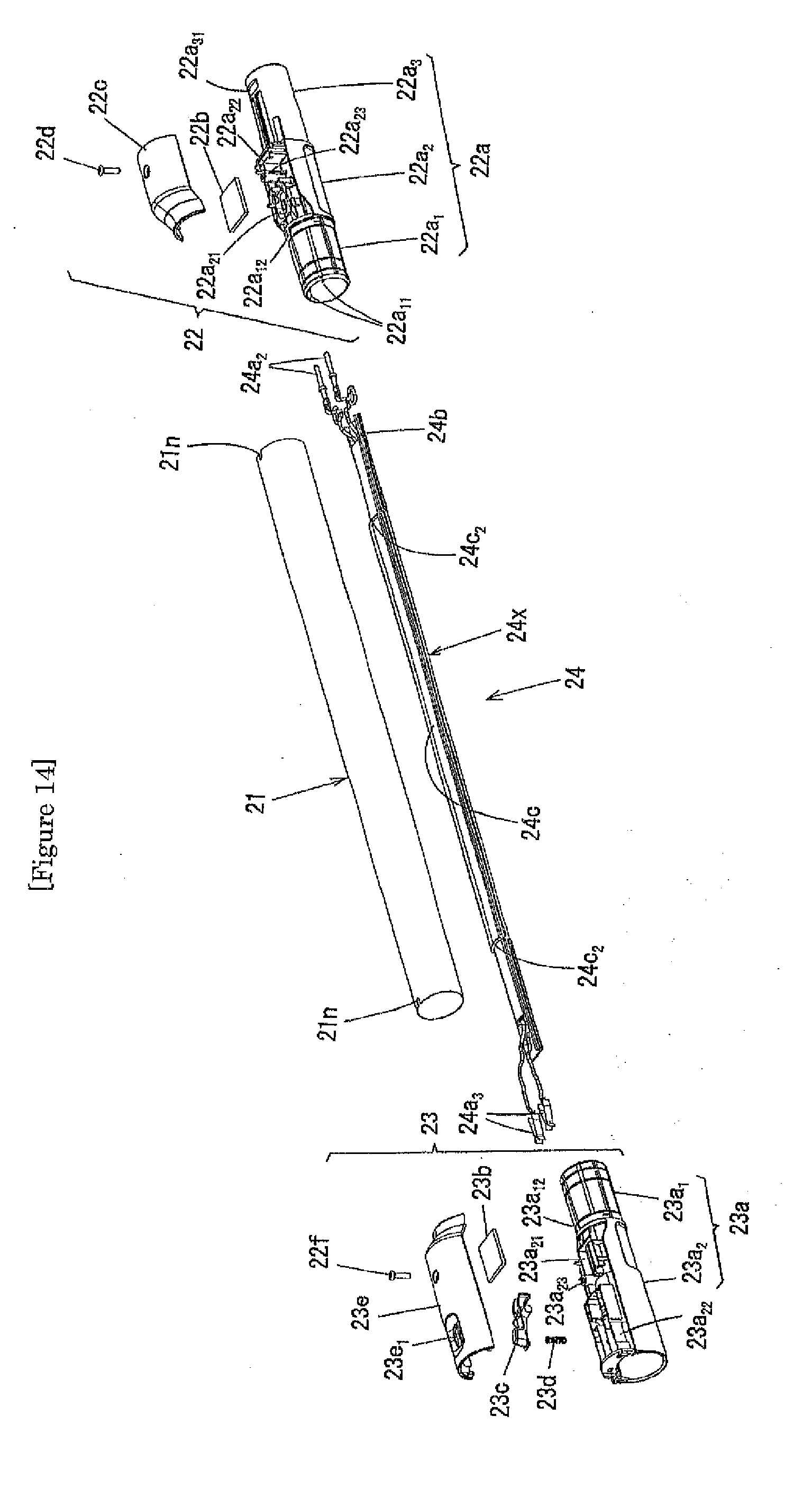
D00014
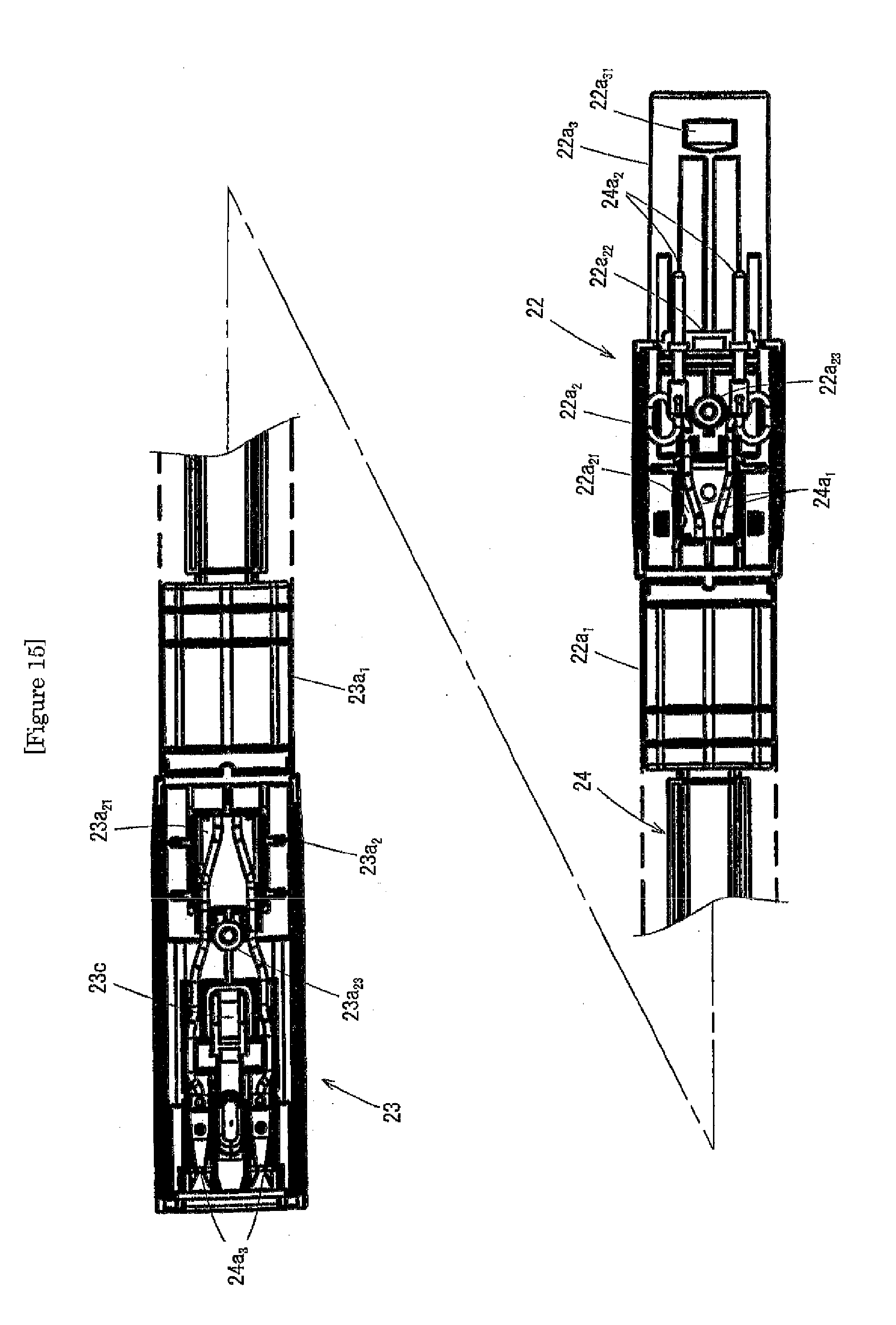
D00015
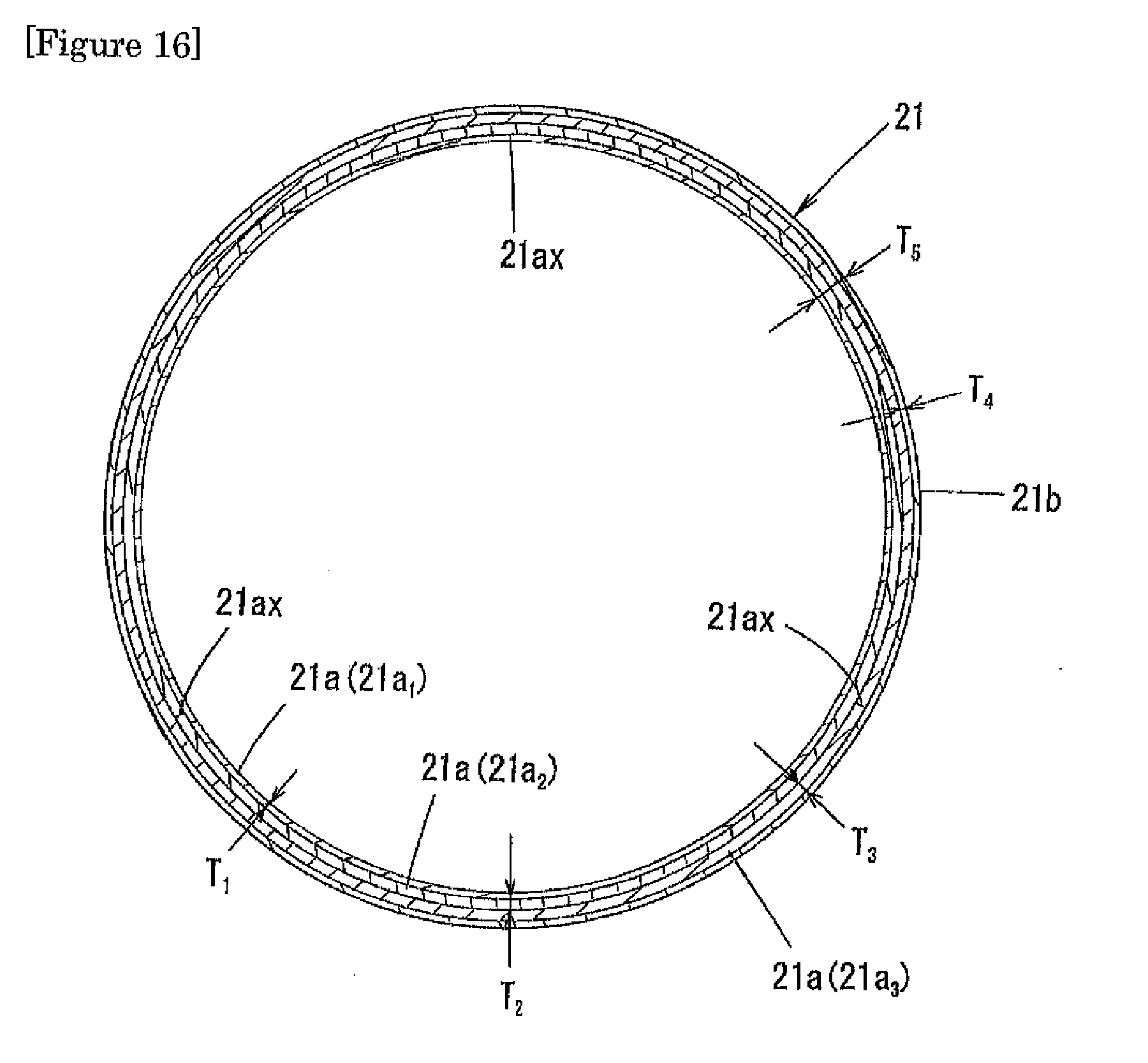
D00016

D00017

D00018
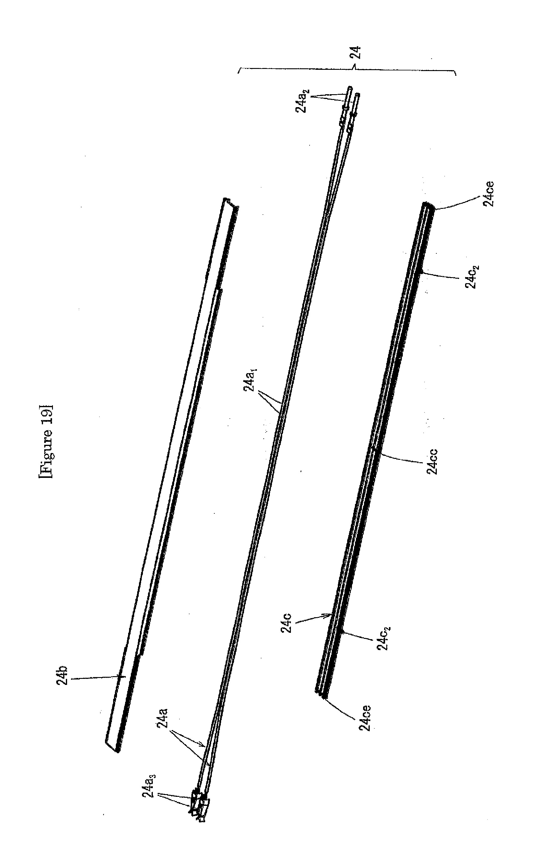
D00019
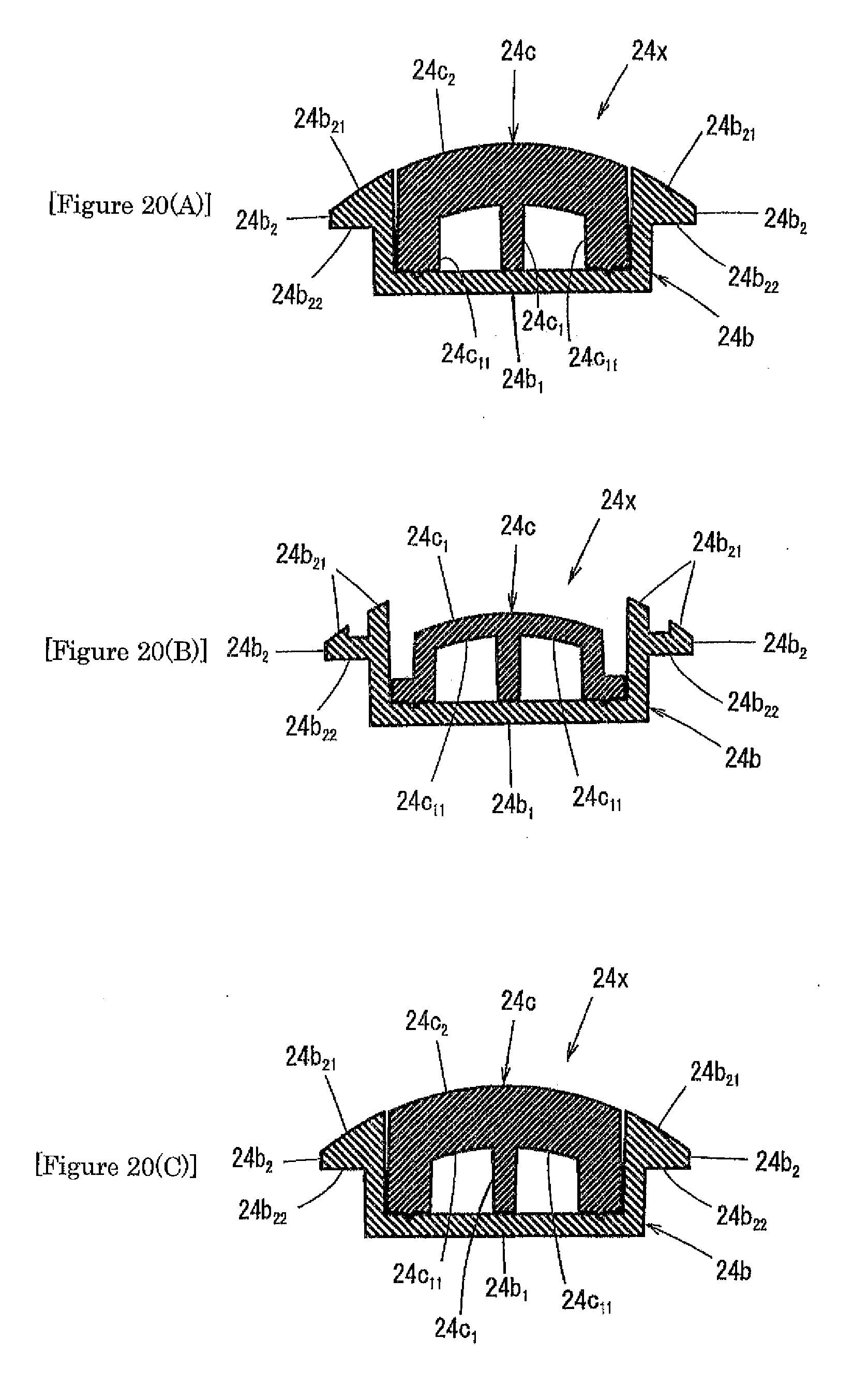
D00020
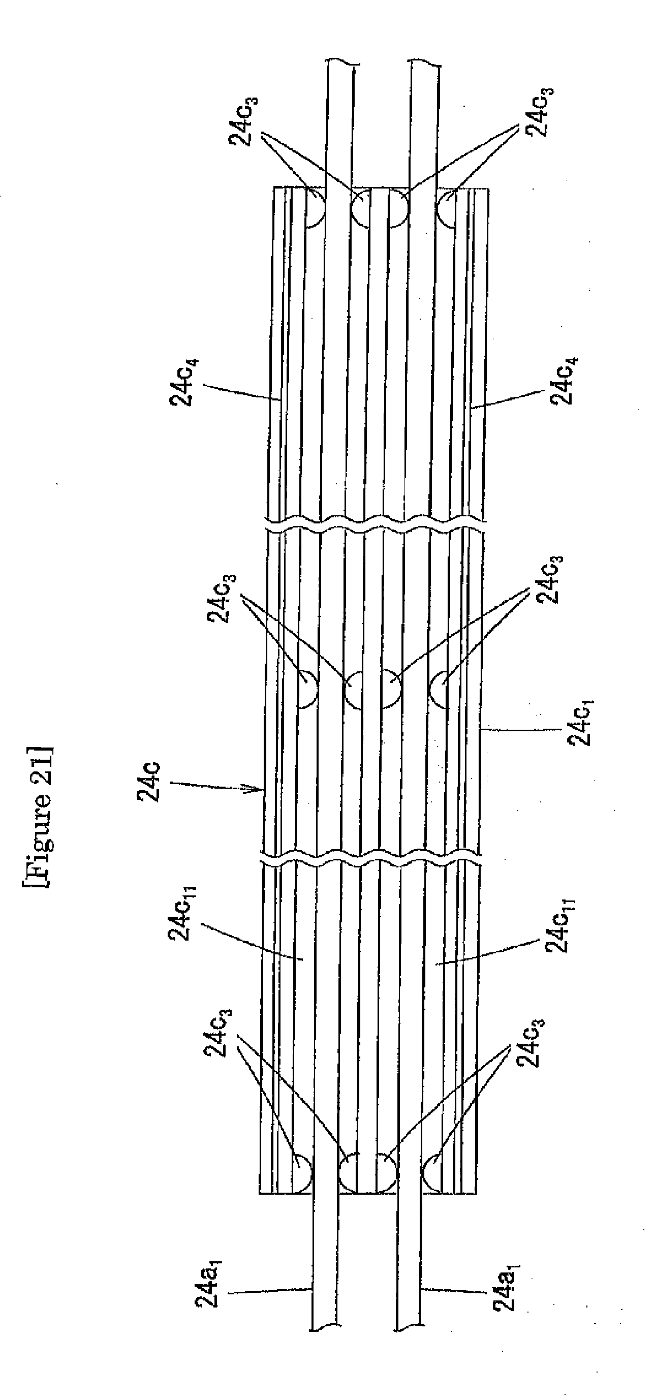
D00021
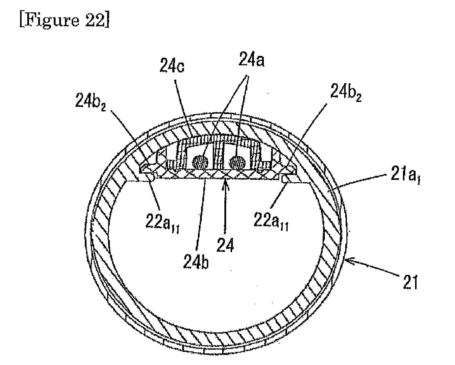
D00022

D00023
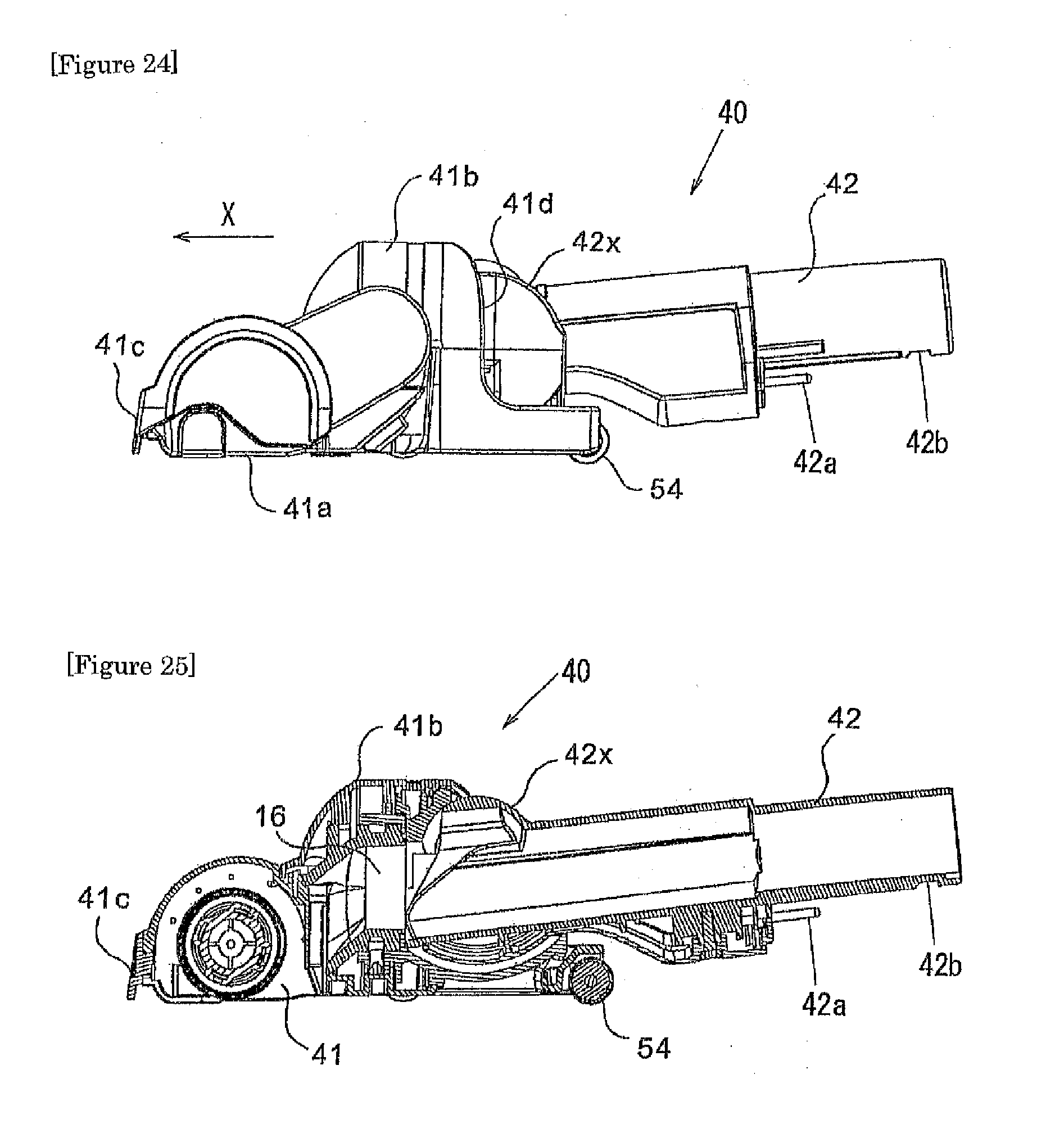
D00024
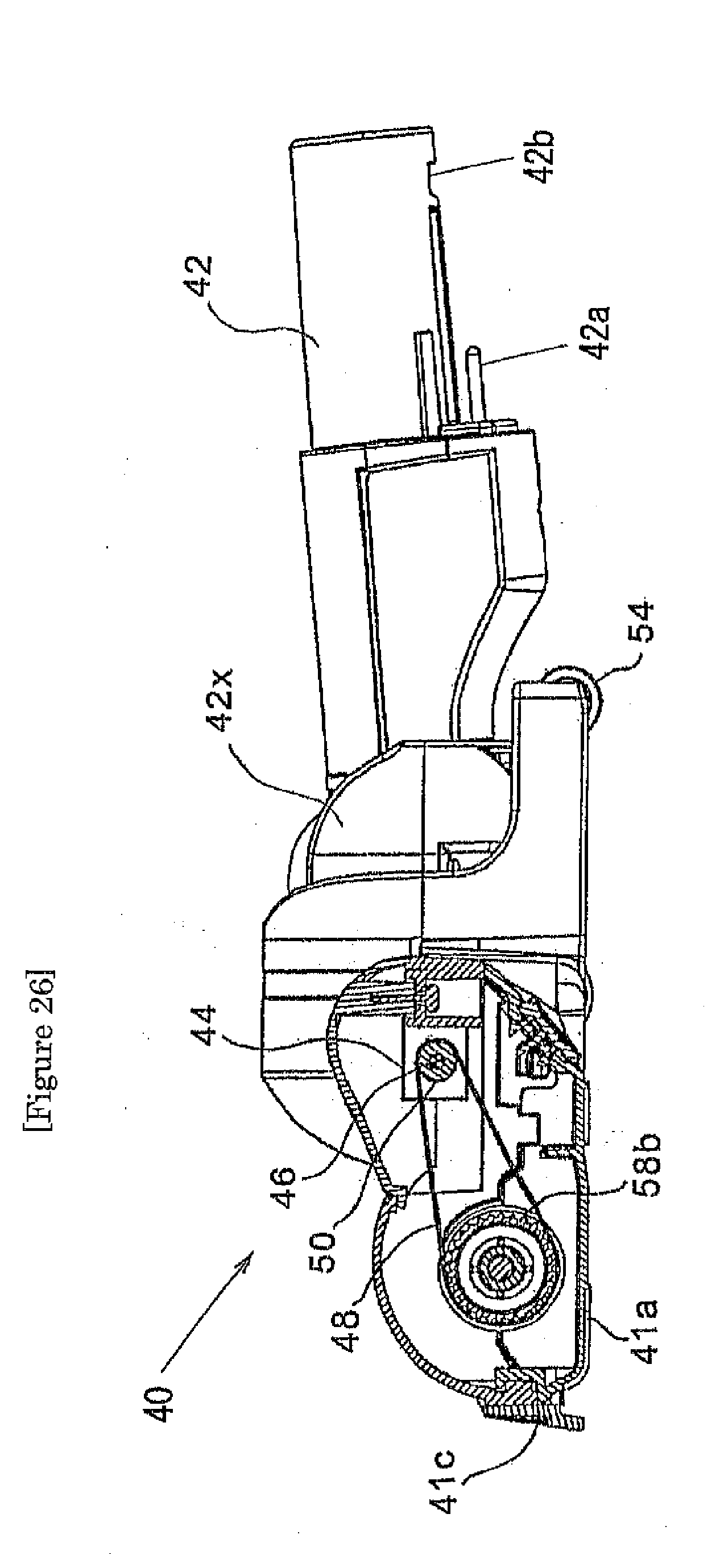
XML
uspto.report is an independent third-party trademark research tool that is not affiliated, endorsed, or sponsored by the United States Patent and Trademark Office (USPTO) or any other governmental organization. The information provided by uspto.report is based on publicly available data at the time of writing and is intended for informational purposes only.
While we strive to provide accurate and up-to-date information, we do not guarantee the accuracy, completeness, reliability, or suitability of the information displayed on this site. The use of this site is at your own risk. Any reliance you place on such information is therefore strictly at your own risk.
All official trademark data, including owner information, should be verified by visiting the official USPTO website at www.uspto.gov. This site is not intended to replace professional legal advice and should not be used as a substitute for consulting with a legal professional who is knowledgeable about trademark law.