Cartridge And Electronic Cigarette Having Same
QIU; WEIHUA
U.S. patent application number 16/336096 was filed with the patent office on 2019-07-11 for cartridge and electronic cigarette having same. The applicant listed for this patent is JOYETECH EUROPE HOLDING GMBH. Invention is credited to WEIHUA QIU.
| Application Number | 20190208825 16/336096 |
| Document ID | / |
| Family ID | 61689830 |
| Filed Date | 2019-07-11 |


| United States Patent Application | 20190208825 |
| Kind Code | A1 |
| QIU; WEIHUA | July 11, 2019 |
CARTRIDGE AND ELECTRONIC CIGARETTE HAVING SAME
Abstract
A cartridge and an electronic cigarette having the cartridge are disclosed. The cartridge includes a top wall and a peripheral wall. The top wall and the peripheral wall surrounds a liquid storage chamber of the cartridge. The peripheral wall is defined with an air inflow passage and a smoke outflow passage. The air inflow passage is located at one side of the peripheral wall, and the smoke outflow passage is located at the other side of the peripheral wall opposite to the air inflow passage.
| Inventors: | QIU; WEIHUA; (Changzhou City, Jiangsu Province, CN) | ||||||||||
| Applicant: |
|
||||||||||
|---|---|---|---|---|---|---|---|---|---|---|---|
| Family ID: | 61689830 | ||||||||||
| Appl. No.: | 16/336096 | ||||||||||
| Filed: | September 27, 2017 | ||||||||||
| PCT Filed: | September 27, 2017 | ||||||||||
| PCT NO: | PCT/CN2017/103701 | ||||||||||
| 371 Date: | March 22, 2019 |
| Current U.S. Class: | 1/1 |
| Current CPC Class: | A24F 47/00 20130101; A24F 40/10 20200101; A24F 40/42 20200101; A24F 47/008 20130101; A24F 40/485 20200101 |
| International Class: | A24F 47/00 20060101 A24F047/00 |
Foreign Application Data
| Date | Code | Application Number |
|---|---|---|
| Sep 22, 2016 | CN | 201610847097.9 |
Claims
1. An electronic cigarette comprising a cartridge and an atomizing assembly, the cartridge having a liquid storage chamber, a bottom end of the liquid storage chamber being open, the atomizing assembly comprising an atomizing head, wherein the cartridge comprises a top wall and a peripheral wall, the top wall and the peripheral wall surrounds the liquid storage chamber, the peripheral wall is provided with an air inflow passage on one side of the cartridge, the peripheral wall is provided with a smoke outflow passage on the other side of the cartridge, the atomizing head is disposed at a bottom side of the cartridge, the atomizing head has an atomizing channel, one end of the atomizing channel communicates with the air inflow passage, the other end of the atomizing channel communicates with the smoke outflow passage, an outer wall of the atomizing head is provided with a liquid inlet hole, the liquid inlet hole communicates with the liquid storage chamber, the cigarette liquid in the liquid storage chamber flows through the liquid inlet hole into the atomizing channel to be atomized into smoke.
2. The electronic cigarette according to claim 1, wherein a top end of the liquid storage chamber is closed, the air inflow passage extends axially from a bottom end of the peripheral wall to a preset height, the peripheral wall correspondingly defines an air inlet hole which communicates with a top end of the air inflow passage.
3. The electronic cigarette according to claim 1, wherein the smoke outflow passage extends axially from a bottom end of the peripheral wall to a top end of the peripheral wall and penetrates the top end and the bottom end of the peripheral wall.
4. The electronic cigarette according to claim 1, wherein the peripheral wall or the top wall is defined with a liquid injection hole.
5. The electronic cigarette according to claim 2, wherein an air guiding tab is provided at a bottom surface of the peripheral wall of the cartridge corresponding to an outlet of the air inflow passage and an inlet of the smoke outflow passage, the two air guiding tabs are oppositely disposed, the airflow flowing out from the air inflow passage is guided by the air guiding tab to the smoke outflow passage, and the airflow is then guided into the smoke outflow passage by the air guiding tab of the smoke outflow passage.
6. The electronic cigarette according to claim 1, wherein a liquid retaining ring is sleeved on each of two ends of an outer wall of the atomizing head, a plurality of liquid inlet holes are formed in the outer wall of the atomizing head between the two liquid retaining rings, the atomizing head comprises a first casing disposed at one end, a second casing disposed at the other end, and an insulating member disposed between the first casing and the second casing, the atomizing head further comprises a heating member and a liquid absorbing member, the liquid absorbing member is wrapped around an outer periphery of the heating member, and together mounted in an inner chamber of the first casing.
7. The electronic cigarette according to claim 1, further comprising a housing, the housing comprising an upper housing and a lower housing matched with the upper housing, a latching hole is formed at a connecting portion between the upper housing and the lower housing, an upper end of the cartridge is installed in the upper housing, a lower end of the cartridge and the atomizing assembly are mounted in the lower housing.
8. The electronic cigarette according to claim 1, wherein two ends of the atomizing channel of the atomizing head are respectively aligned with an outlet of the air inflow passage and an inlet of the smoke outflow passage; the air inflow passage, the smoke outflow passage and the atomizing channel cooperatively form a U-shaped airflow passage which surrounds the liquid storage chamber of the cartridge.
9. The electronic cigarette according to claim 8, further comprising a control assembly, wherein the control assembly comprises a mounting bracket, the mounting bracket is formed with a partition wall adjacent to the atomizing head, the mounting bracket is mounted with a sensor, the partition wall is provided with a suction sensing channel, the suction sensing channel communicates the airflow passage of the electronic cigarette with the sensor.
10. The electronic cigarette according to claim 9, wherein the control assembly comprises a pole contacting member, the mounting bracket is mounted with a circuit board, the partition wall is provided with a mounting hole, the pole contacting member is mounted in the mounting hole (412) for electrically connecting the circuit board with the atomizing head.
11. A cartridge, wherein the cartridge comprises a top wall and a peripheral wall, the top wall and the peripheral wall surrounds a liquid storage chamber, the peripheral wall is defined with an air inflow passage and a smoke outflow passage, the air inflow passage is located at one side of the peripheral wall, and the smoke outflow passage is located at the other side of the peripheral wall opposite to the air inflow passage.
12. The cartridge according to claim 11, wherein a bottom end of the liquid storage chamber is open.
13. The cartridge according to claim 11, wherein the peripheral wall or the top wall is defined with a liquid injection hole.
14. The cartridge according to claim 11, wherein the peripheral wall is defined with an air inlet hole, and the air inlet hole communicates with the air inflow passage.
15. The cartridge according to claim 11, wherein the smoke outflow passage extends axially from a bottom end of the peripheral wall to a top end of the peripheral wall and penetrates the top end and the bottom end of the peripheral wall.
16. The cartridge according to claim 11, wherein the air inflow passage extends axially from a bottom end of the peripheral wall to a preset height.
17. An electronic cigarette comprising the cartridge according to claim 11.
18. The electronic cigarette according to claim 17, further comprising a housing, wherein the cartridge is mounted in the housing, and the housing has a smoke exhaust hole at a top end thereof.
19. The electronic cigarette according to claim 17, further comprising an atomizing assembly, wherein the atomizing assembly comprises an atomizing head, an atomizing channel is defined in the atomizing head, one end of the atomizing channel communicates with the air inflow passage, the other end of the atomizing channel communicates with the smoke outflow passage, an outer wall of the atomizing head is defined with a liquid inlet hole, and the liquid inlet hole communicates with the liquid storage chamber.
20. The electronic cigarette according to claim 17, further comprising a suction sensing channel and a sensor, wherein the air inflow passage, the smoke outflow passage and the atomizing channel cooperatively form an airflow passage of the electronic cigarette, two ends of the suction sensing channel are communicated with the sensor and the airflow passage, respectively.
Description
TECHNICAL FIELD
[0001] The present invention relates to the technical field of electronic cigarette, and more particularly to an improved cartridge and an electronic cigarette having same.
BACKGROUND
[0002] The air intake system of existing electronic cigarette is basically a vertical up and down air intake mode, and the atomizing head of the electronic cigarette is inserted into the liquid storage chamber of the cartridge, so as to provide cigarette liquid to the atomizing head, which is inconvenient for the replacement of the atomizing head. Further, the air intake mode of the existing electronic cigarette is that the air inlet hole of the electronic cigarette is formed at the bottom of the housing of the electronic cigarette. However, the air inlet hole at the bottom is easy to cause leakage of the cigarette liquid when inhaling.
SUMMARY
[0003] In view of the above, in order to meet the needs of the market, it is necessary to provide an electronic cigarette to facilitate replacement of the atomizing head and to avoid leakage of the cigarette liquid when inhaling.
[0004] A first aspect of the present invention provides an electronic cigarette which includes a cartridge and an atomizing assembly. The cartridge has a liquid storage chamber. A bottom end of the liquid storage chamber is open. The atomizing assembly includes an atomizing head. The cartridge includes a top wall and a peripheral wall. The top wall and the peripheral wall surrounds the liquid storage chamber. The peripheral wall is provided with an air inflow passage at one side of the cartridge. The peripheral wall is provided with a smoke outflow passage at the other side of the cartridge. The atomizing head is disposed at a bottom side of the cartridge. The atomizing head has an atomizing channel, one end of the atomizing channel communicates with the air inflow passage, the other end of the atomizing channel communicates with the smoke outflow passage. An outer wall of the atomizing head is provided with a liquid inlet hole. The liquid inlet hole communicates with the liquid storage chamber. The cigarette liquid in the liquid storage chamber flows through the liquid inlet hole into the atomizing channel to be atomized into smoke.
[0005] In one embodiment, a top end of the liquid storage chamber is closed. The air inflow passage extends axially from a bottom end of the peripheral wall to a preset height. The peripheral wall correspondingly defines an air inlet hole which communicates with a top end of the air inflow passage.
[0006] In one embodiment, the smoke outflow passage extends axially from a bottom end of the peripheral wall to a top end of the peripheral wall and penetrates the top end and the bottom end of the peripheral wall.
[0007] In one embodiment, the peripheral wall or the top wall is defined with a liquid injection hole.
[0008] In one embodiment, an air guiding tab is provided at a bottom surface of the peripheral wall of the cartridge corresponding to an outlet of the air inflow passage and an inlet of the smoke outflow passage. The two air guiding tabs are oppositely disposed. The airflow flowing out from the air inflow passage is guided by the air guiding tab to the smoke outflow passage, and the airflow is then guided into the smoke outflow passage by the air guiding tab of the smoke outflow passage.
[0009] In one embodiment, a liquid retaining ring is sleeved on each of two ends of an outer wall of the atomizing head. A plurality of liquid inlet holes are formed in the outer wall of the atomizing head between the two liquid retaining rings. The atomizing head includes a first casing disposed at one end, a second casing disposed at the other end, and an insulating member disposed between the first casing and the second casing. The atomizing head further includes a heating member and a liquid absorbing member. The liquid absorbing member is wrapped around an outer periphery of the heating member, and together mounted in an inner chamber of the first casing.
[0010] In one embodiment, the electronic cigarette further includes a housing. The housing includes an upper housing and a lower housing matched with the upper housing. A latching hole is formed at a connecting portion between the upper housing and the lower housing. An upper end of the cartridge is installed in the upper housing, a lower end of the cartridge and the atomizing assembly are mounted in the lower housing.
[0011] In one embodiment, two ends of the atomizing channel of the atomizing head are respectively aligned with an outlet of the air inflow passage and an inlet of the smoke outflow passage. The air inflow passage, the smoke outflow passage and the atomizing channel cooperatively form a U-shaped airflow passage which surrounds the liquid storage chamber of the cartridge.
[0012] In one embodiment, the electronic cigarette further includes a control assembly. The control assembly includes a mounting bracket. The mounting bracket is formed with a partition wall adjacent to the atomizing head. The mounting bracket is mounted with a sensor. The partition wall is provided with a suction sensing channel. The suction sensing channel communicates the airflow passage of the electronic cigarette with the sensor.
[0013] In one embodiment, the control assembly includes a pole contacting member. The mounting bracket is mounted with a circuit board. The partition wall is provided with a mounting hole. The pole contacting member is mounted in the mounting hole for electrically connecting the circuit board with the atomizing head.
[0014] A second aspect of the present invention provides a cartridge which includes a top wall and a peripheral wall. The top wall and the peripheral wall surrounds a liquid storage chamber. The peripheral wall is defined with an air inflow passage and a smoke outflow passage. The air inflow passage is located at one side of the peripheral wall, and the smoke outflow passage is located at the other side of the peripheral wall opposite to the air inflow passage.
[0015] In one embodiment, a bottom end of the liquid storage chamber is open.
[0016] In one embodiment, the peripheral wall or the top wall is defined with a liquid injection hole.
[0017] In one embodiment, the peripheral wall is defined with an air inlet hole, and the air inlet hole communicates with the air inflow passage.
[0018] In one embodiment, the smoke outflow passage extends axially from a bottom end of the peripheral wall to a top end of the peripheral wall and penetrates the top end and the bottom end of the peripheral wall.
[0019] In one embodiment, the air inflow passage extends axially from a bottom end of the peripheral wall to a preset height.
[0020] A third aspect of the present invention provides an electronic cigarette which includes the cartridge of any one according to the second aspect of the present invention.
[0021] In one embodiment, the electronic cigarette further includes a housing. The cartridge is mounted in the housing, and the housing has a smoke exhaust hole at a top end thereof.
[0022] In one embodiment, the electronic cigarette further includes an atomizing assembly. The atomizing assembly includes an atomizing head. An atomizing channel is defined in the atomizing head, one end of the atomizing channel communicates with the air inflow passage, and the other end of the atomizing channel communicates with the smoke outflow passage. An outer wall of the atomizing head is defined with a liquid inlet hole, and the liquid inlet hole communicates with the liquid storage chamber.
[0023] In one embodiment, the electronic cigarette further includes a suction sensing channel and a sensor. The air inflow passage, the smoke outflow passage and the atomizing channel cooperatively form an airflow passage of the electronic cigarette. Two ends of the suction sensing channel are communicated with the sensor and the airflow passage, respectively.
[0024] Compared with the prior art, the electronic cigarette provided by the invention utilizes the peripheral wall of the cartridge for air inflow and outflow. It is thus not required to additionally provide a sleeve for air inflow and outflow, to save material and save cost. Further, the liquid storage chamber, the air inflow passage and the smoke outflow passage are integrated, thereby reducing the difficulty of assembling, saving the internal space of the electronic cigarette to the greatest extent and further reducing the volume of the electronic cigarette. In one embodiment, the atomizing head is disposed under the cartridge without being inserted into an interior of the cartridge, further solving the problem that the atomizing head of the existing electronic cigarette needs to be inserted into the interior of the cartridge. In one embodiment, the air intake mode is a surrounding type air intake mode, and the surrounding type air intake mode solves the problem that the air inlet hole of the existing electronic cigarette is defined at the bottom of the housing of the electronic cigarette, and the air inlet hole at the bottom is easy to cause the leakage problem when inhaling. Also, the airflow is smoother and the suction effect is better.
[0025] Preferred embodiments of the present invention and its advantageous effects will be further described in detail in conjunction with the specific embodiments.
BRIEF DESCRIPTION OF THE DRAWINGS
[0026] The drawings are intended to provide a further understanding of the present invention and form part of the specification for explaining the invention in conjunction with the following specific embodiments, but shall not constitute a limitation on the invention. In the drawing:
[0027] FIG. 1 is a perspective view of an electronic cigarette according to a preferred embodiment of the present invention;
[0028] FIG. 2 is a cross-sectional view of the electronic cigarette shown in FIG. 1;
[0029] FIG. 3 is a perspective view of the cartridge of the electronic cigarette shown in FIG. 1;
[0030] FIG. 4 is a side view of the cartridge of the electronic cigarette shown in FIG. 3;
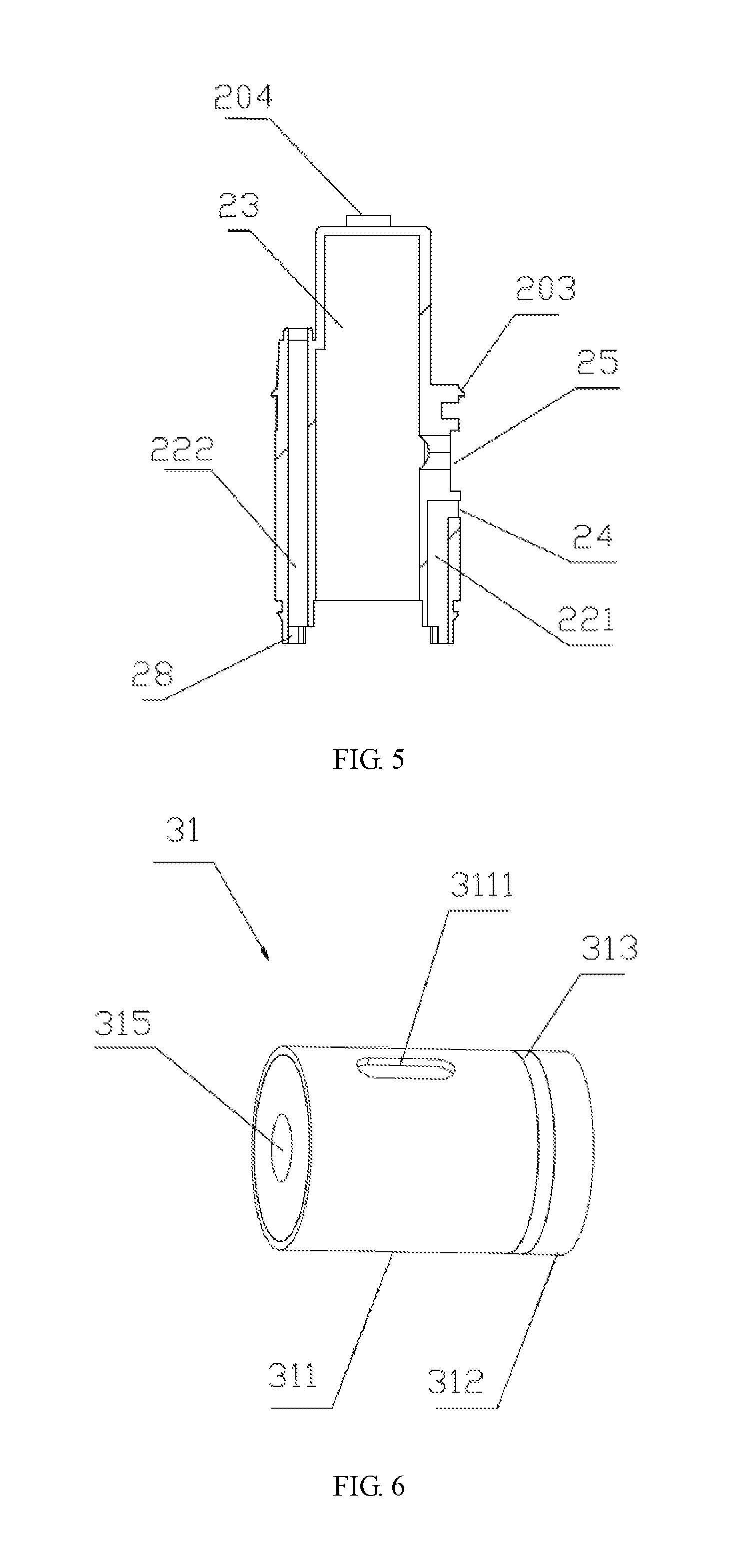
[0031] FIG. 5 is a cross-sectional view of the cartridge along line B-B shown in FIG. 4;
[0032] FIG. 6 is a perspective view of an atomizing head of an electronic cigarette according to a preferred embodiment of the present invention;
[0033] FIG. 7 is a cross-sectional view of the atomizing head shown in FIG. 6;
[0034] FIG. 8 is a front view of an atomizing head of an electronic cigarette according to another preferred embodiment of the present invention.
NAMES OF COMPONENTS AND REFERENCE SIGNS
TABLE-US-00001 [0035] housing 10 latching block 26 upper housing 11 liquid filling plug 27 lower housing 12 air guiding tab 28 latching hole 13 atomizing head 31 slot 14 atomizing head sleeve 32 cartridge 20 control assembly 40 top wall 21 mounting bracket 41 peripheral wall 22 circuit board 42 liquid storage chamber 23 pole contacting member 43 air inlet hole 24 sensor 44 liquid injection hole 25 smoke exhaust hole 111 atomizing assembly 30 center line 201 power source 45 insulating member 313 air intake hole 121 electrical connecting leg 314 USB interface 123 atomizing channel 315 cutout 202 liquid absorbing member 317 clip 203 liquid retaining ring 318 protrusion 204 liquid passing hole 321 air inflow passage 221 pole connecting hole 322 smoke outflow passage 222 partition wall 411 smoke outlet hole 223 mounting hole 412 first casing 311 suction sensing channel 413 second casing 312 USB slot 421 heating member 316 liquid inlet hole 3111
DETAILED DESCRIPTION OF PREFERRED EMBODIMENTS
[0036] The specific embodiments of the present invention will be described in detail below with reference to the accompanying drawings. It is to be understood that the specific embodiments described herein are merely illustrative and not restrictive.
[0037] Referring to FIG. 1 and FIG. 2, the present invention provides an electronic cigarette including a housing 10, a cartridge 20 mounted in the housing 10, an atomizing assembly 30, and a control assembly 40. The cartridge 20 is mounted at the upper end of the housing 10 for providing cigarette liquid to the atomizing assembly 30. The atomizing assembly 30 is mounted at the bottom side of the cartridge 20 for atomizing the inflowing cigarette liquid. Optionally, the control assembly 40 is mounted at the bottom side of the atomizing assembly 30 for supplying power to the atomizing assembly 30 and controlling the start and/or stop of atomization in a timely manner.
[0038] The housing 10 includes an upper housing 11 and a lower housing 12 matched with the upper housing. The connecting portion of the upper housing 11 and the lower housing 12 is formed with a latching hole 13 for alignment when the cartridge 20 is installed in the upper housing 11 and the lower housing 12. In this embodiment, two latching holes 13 are oppositely disposed at the connecting portion between the upper housing 11 and the lower housing 12 for quick assembly of the cartridge 20. The upper housing 11 is shorter than the lower housing 12, and the upper housing 11 is located at the upper end of the housing 10. In one embodiment, the upper housing 11 can be regarded as a cap, and the top end thereof is provided with a smoke exhaust hole 111 for the smoke to be exhausted. Optionally, the smoke exhaust hole 111 can be connected to a mouthpiece (not shown). The upper end of the cartridge 20 is installed in the upper housing 11, and a portion of the cartridge 20 can extend out of the upper housing 11. The upper housing 11 is further formed with a slot 14 for the cartridge 20 to be snapped, so that the cartridge 20 can be stably held in the upper housing 11. In one embodiment, the lower housing 12 can be regarded as a main body, and an air intake hole 121 and a USB interface 123 are defined in a peripheral wall thereof. The atomizing assembly 30, the control assembly 40 and the lower end of the cartridge 20 are mounted in the lower housing 12. Since the housing 10 has a structure that is formed by cooperating the upper housing 11 with the lower housing 12, it is facilitated to assemble and disassemble the cartridge 20 and the atomizing assembly 30 in the electronic cigarette.
[0039] Referring to FIG. 3, FIG. 4, and FIG. 5, the cartridge 20 includes a top wall 21 and a peripheral wall 22, and the top wall 21 and the peripheral wall 22 cooperates to define a liquid storage chamber 23 therein. The liquid storage chamber 23 is closed at the top end, with an opening at the bottom end. In one embodiment, the opening may be a whole through hole or consisted of a plurality of small through holes. An air inflow passage 221 and a smoke outflow passage 222 are formed axially in the peripheral wall 22 of the cartridge 20. The air inflow passage 221 is located at one side of the peripheral wall 22 of the cartridge, and the smoke outflow passage 222 is located at the other side of the peripheral wall 22 opposite to the air inflow passage 221. It can be understood that the peripheral wall 22 is made of a plate with a certain thickness, so that the peripheral wall 22 can allow the air inflow passage 221 and the smoke outflow passage 222 to be formed inside the peripheral wall 22 perpendicularly to the thickness direction thereof. In one embodiment, the air inflow passage 221 extends axially from the bottom end of the peripheral wall 22 to a certain height. In one embodiment, the peripheral wall 22 correspondingly defines an air inlet hole 24 which communicates with the top end of the air inflow passage 221. After the air is supplied from the air inlet hole 24, it can flow out from the bottom end of the peripheral wall 22 along the air inflow passage 221. In one embodiment, the smoke outflow passage 222 extends axially from the bottom end of the peripheral wall 22 to the top end of the peripheral wall 22, penetrating the top end and the bottom end of the peripheral wall 22 such that the air flows in from the bottom end of the smoke outflow passage 222 and flows out from the top end of the peripheral wall 22. By forming the air inflow passage 221 and the smoke outflow passage 222 in the peripheral wall 22, it can make full use of the peripheral space of the cartridge 20, and it is not necessary to form these passages in the middle of the electronic cigarette where a large number of components are disposed, thereby reducing the volume of the electronic cigarette. Further, the arrangement of the air entering from top and leaving from top can also effectively prevent liquid leakage. A liquid injection hole 25 is radially formed in the peripheral wall 22 for injecting cigarette liquid into the liquid storage chamber 23, and the liquid injection hole 25 is not communicated with the air inflow passage 221 or the smoke outflow passage 222, to ensure direct injection of the cigarette liquid into the liquid storage chamber 23. For example, the liquid injection hole 25 can be defined in the peripheral wall 22 at a position where it does not communicate with the air inflow passage 221 or the smoke outflow passage 222, such as above the air inflow passage 221. Further, the liquid injection hole 25 can also be formed axially through the top wall 21.
[0040] In this embodiment, the cartridge 20 can be divided into a lower half and an upper half integrally formed with the lower half (as separated by the center line 201 in the figure). The lower half is installed in the lower housing 12. The upper half is installed in the upper housing 11. Latching blocks 26 are protruded outwardly from the peripheral wall 22 of the cartridge 20, and the latching blocks 26 are formed at the connecting portion between the lower half and the upper half for engaging in the latching holes 13 formed at the connecting portion between the upper housing 11 and the lower housing 12. In one embodiment, the air inflow passage 221, the air inlet hole 24 and the liquid injection hole 25 are all formed in the lower half at one side of the peripheral wall 22, the air inflow passage 221 extends from the bottom end of the peripheral wall 22 to a certain height and communicates with the air inlet hole 24, the liquid injection hole 25 is located directly above the air inlet hole 24, and the top of the liquid injection hole 25 is flush with the center line 201. The shape of the liquid injection hole 25 is not limited. In this embodiment, the liquid injection hole 25 is formed by a rectangular notch fitted with a central circular hole to facilitate the installation of a liquid filling plug 27 (see FIG. 2). The smoke outflow passage 222 is formed in the peripheral wall 22 at the other side of the liquid storage chamber 23 opposite to the air inflow passage 221, and the smoke outflow passage 222 extends from the bottom end of the peripheral wall 22 through the lower half and then extends into the upper half. In one embodiment, two opposite sides of the upper half are formed with a cutout 202 corresponding to the air inflow passage 221 and the smoke outflow passage 222. The cutout 202 extends downwards from the top end of the upper half to a certain distance. The cutout 202 is not communicated with the liquid storage chamber 23. After the cutout 202 is extended by a certain distance, the bottom surface of the cutout 202 is correspondingly configured as the top surface of the smoke outflow passage 222. In one embodiment, the smoke outflow passage 222 is provided with a smoke outlet hole 223 at the top end of the peripheral wall 22. In one embodiment, by forming the cutouts 202 on both sides of the upper half, the upper half of the cartridge 20 can be fitted into the upper housing 11, to adapt the flat, contracted shape of the upper housing 11. In the case where the outer shape of the upper housing 11 is not considered, the cutouts 202 need not be formed on both sides of the upper half. A clip 203 is formed on the outer circumference of the upper half to engage correspondingly with the slot 14 of the upper housing 11. The top wall of the upper half (corresponding to the top wall 21 of the cartridge 20) is provided with a protrusion 204. After the upper half of the cartridge 20 is inserted into the upper housing 11, the protrusion 204 is engaged with the upper housing 11 to enhance the alignment accuracy and stability. In addition, an air guiding tab 28 is provided at the bottom surface of the peripheral wall 22 of the cartridge 20 corresponding to the outlet of the air inflow passage 221 and the inlet of the smoke outflow passage 222. The air guiding tab 28 is L-shaped, and the two air guiding tabs 28 are oppositely disposed, so that the airflow flowing out from the air inflow passage 221 is guided by the air guiding tab 28 to the side of the smoke outflow passage 222, and the airflow is then guided into the smoke outflow passage 222 by the air guiding tab 28 of the smoke outflow passage 222. According to the ventilation needs of the components of the control assembly 40, the air guiding tab 28 can be omitted or perforated, such that when inhaling, the control assembly 40 is activated and the suction airflow passes through the air guiding tab 28 to enter into the air inflow passage 221. In this embodiment, the oppositely disposed L-shaped air guiding tabs 28 can guide the airflow, to ensure that the airflow smoothly enters the smoke outflow passage 222 from the air inflow passage 221 and to improve the sealing property with the two ends of the atomizing head 31.
[0041] The atomizing assembly 30 is mounted at the bottom side of the cartridge 20, and the two ends of the atomizing assembly 30 are communicated with the outlet of the air inflow passage 221 and the inlet of the smoke outflow passage 222, respectively. The atomizing assembly 30 atomizes the cigarette liquid flowing in from the liquid storage chamber 23 of the cartridge 20 to form smoke, and the smoke is carried out through the airflow. The atomizing assembly 30 includes an atomizing head 31. Referring to FIG. 6 and FIG. 7, the atomizing head 31 has a cylindrical shape, and includes a first casing 311 disposed at one end, a second casing 312 disposed at the other end, and an insulating member 313 disposed between the first casing 311 and the second casing 312. The first casing 311 and the second casing 312 serve as the peripheral wall of the atomizing head 31 and are each electrically conductive, for respectively connecting two electric poles, wherein one of them is connected to the positive pole and the other is connected to the negative pole. An electrical connecting leg 314 is provided on each of the first casing 311 and the second casing 312 for connecting to the electric pole. The atomizing head 31 defines an atomizing channel 315 in the axial direction to penetrate both ends of the atomizing head 31. The first casing 311 is longer than the second casing 312. The outer wall of the first casing 311 is provided with a liquid inlet hole 3111 for the cigarette liquid in the liquid storage chamber 23 to flow into the atomizing head 31 through the liquid inlet hole 3111. It is noted that the atomizing channel 315 is a place where the cigarette liquid is atomized into smoke, allowing the airflow to pass therethrough. The airflow enters from one end of the atomizing channel 315, and exits from the other end of the atomizing channel 315 while carrying the smoke generated from the cigarette liquid in the atomizing channel 315.
[0042] In one embodiment, the atomizing head 31 includes a heating member 316 and a liquid absorbing member 317. The liquid absorbing member 317 is wrapped around the outer periphery of the heating member 316, and together mounted in the inner chamber of the first casing 311. The heating member 316 is selected as a spiral formed by spiraling a heating wire, and the inside of the spiral serves as the atomizing channel 315. One end of the heating wire is connected to the first casing 311, and the other end of the heating wire is connected to the second casing 312. The other parts of the heating wire are not in contact with the first casing 311 and the second casing 312. Optionally, the heating member 316 is a heating wire wound by a nickel alloy. Optionally, the liquid absorbing member 317 is selected as a liquid absorbent cotton or a fiber rope. In addition, the specific structure of the atomizing head may also be that the heating member wrapped around the outer periphery of the liquid absorbing member. The atomizing channel 315 is an atomizing chamber with both ends being penetrated, wherein the heating member and the liquid absorbing member are disposed in the atomizing chamber. In this way, the cigarette liquid in the liquid storage chamber of the cartridge 20 flows in through the liquid inlet hole 3111 and is absorbed by the liquid absorbing member 317. When conducting the heating wire 316, the heating wire 316 generates heat to evaporate the cigarette liquid absorbed on the liquid absorbing member 317 into smoke. The airflow in the air inflow passage 221 enters into the atomizing channel 315, to carry the smoke in the atomizing channel 315 into the smoke outflow passage 222. In this embodiment, the first casing 311 is selected to be connected to the positive pole, and the second casing 312 is selected to be connected to the negative pole. It can be understood that the polarities for the first casing 311 and the second casing 312 may be interchangeable. As such, the atomizing head has a simple structure and can be placed horizontally, which is advantageous for reducing the vertical height of the electronic cigarette.
[0043] Referring to FIG. 8, a preferred embodiment of the present invention further provides an improved atomizing head 31. The improvement is that a plurality of liquid inlet holes 3111 are formed in the outer wall of the atomizing head 31. A liquid retaining ring 318 is sleeved on each of the two ends of the outer wall of the atomizing head 31, so that the plurality of liquid inlet holes 3111 formed in the outer wall are located between the two liquid retaining rings 318, to ensure that the cigarette liquid only flows into the atomizing head 31 and prevents the cigarette liquid from entering other places. The liquid retaining ring 318 may be a rubber ring. The liquid inlet holes 3111 can be formed on the first casing 311 and/or the second casing 312. Optionally, the plurality of liquid inlet holes 3111 are formed only at one side of the first casing 311 facing the liquid storage chamber and corresponding to the liquid absorbing member. In this way, the contact atomizing effect between the liquid absorbing member 317 and the cigarette liquid is better, and the amount of smoke is larger.
[0044] Referring to FIG. 2 again, in order to facilitate the installation of the atomizing head 31 and improve the sealing property between the atomizing head 31 and the liquid storage chamber after installation, the atomizing assembly 30 further includes an atomizing head sleeve 32 for mounting to the bottom side of the cartridge 20 with the atomizing head 31. In one embodiment, the atomizing head sleeve 32 has a tube shape, and one side of the tube wall is provided with a liquid passing hole 321 and the opposite side is provided with a pole connecting hole 322. The side of the atomizing head sleeve 32 having the liquid passing hole 321 is held in the liquid storage chamber of the cartridge 20, and the two ends of the atomizing head sleeve 32 closely abut against the inner wall of the liquid storage chamber, thereby improving the sealing effect at the bottom end of the liquid storage chamber, so that the cigarette liquid flows only along the tube wall of the atomizing head sleeve 32, and flows into the liquid inlet hole 3111 of the atomizing head 31 from the liquid passing hole 321. The atomizing head sleeve 32 may be a rubber sleeve. It can be understood that, in one embodiment, the atomizing head 31 can be mounted directly to the bottom side of the cartridge, and the atomizing head sleeve 32 can be omitted. In addition, when the atomizing head 31 has the liquid retaining rings 318, the atomizing head sleeve 32 is sleeved on the outer circumference of the two liquid retaining rings 318.
[0045] After the atomizing assembly 30 is installed, the two ends of the atomizing channel 315 of the atomizing head 31 are respectively aligned with the outlet of the air inflow passage 221 and the inlet of the smoke outflow passage 222. The air inflow passage 221, the smoke outflow passage 222 and the atomizing channel 315 cooperatively form an airflow passage in the electronic cigarette, which is a U-shaped airflow passage surrounding the liquid storage chamber 23, to solve the problem that the air inlet hole of the existing electronic cigarette is defined at the bottom of the housing, and the air inlet hole at the bottom is easy to cause leakage of cigarette liquid. Meanwhile, the airflow is smoother and the suction effect is better. Further, the atomizing head 31 is disposed at the bottom side of the cartridge 20 without being placed into the liquid storage chamber of the cartridge 20, to facilitate the assembling and disassembling of the atomizing head 31.
[0046] The control assembly 40 is configured to supply power to the atomizing head 31 in response to the suction action. The control assembly 40 includes a mounting bracket 41 and a circuit board 42, a pole contacting member 43, a sensor 44 and a power source 45, which are mounted on the mounting bracket 41. The mounting bracket 41 is mounted in the lower housing 12. The mounting bracket 41 is provided with mounting spaces corresponding to the circuit board 42, the pole contacting member 43, the sensor 44 and the power source 45. A partition wall 411 is formed on the mounting bracket 41 between the circuit board 42 and the atomizing head 31. A mounting hole 412 and a suction sensing channel 413 are defined in the partition wall 411. The mounting hole 412 is used for mounting the pole contacting member 43, so that the circuit board 42 is electrically connected to the atomizing head 31. The suction sensing channel 413 communicates the airflow passage of the electronic cigarette with the sensor 44. The sensor 44 is generally an airflow sensor or an air pressure sensor. During suction, the airflow flows along the air inflow passage 221 and the smoke outflow passage 222, and a negative pressure is formed in the suction sensing channel 413, thereby activating the sensor, causing the circuit board 42 to operate. The circuit board 42 drives the atomizing head 31 to perform the atomizing action. A USB slot 421 is formed in the circuit board 42 to cooperate with the USB interface 123 of the lower housing 12, for connecting to a charger. The power source 45 is detachably mounted on the mounting bracket 41 below the circuit board 42 for supplying power to the circuit board 42 and the atomizing head 31. The power source 45 can be a battery module or a battery cell.
[0047] In this embodiment, the mounting hole 412 is located corresponding to the electrical connecting legs 314 of the atomizing head 31. The suction sensing channel 413 corresponds to the inlet of the smoke outflow passage 222, and is aligned with the smoke outflow passage 222. By omitting the air guiding tab 28 or perforating the air guiding tab 28, the airflow in the suction sensing channel 413 can directly flow into the smoke outflow passage 222 during suction. In one embodiment, the circuit board 42 is an L-shaped board with the pole contacting member 43 being connected to the top end. The pole contacting member 43 is disposed in the mounting hole 412 of the partition wall 411, and the pole contacting member 43 electrically connects the atomizing head 31 and the circuit board 42. Specifically, the pole contacting member 43 includes a positive pole and a negative pole. The positive pole and the negative pole are both connected to the circuit board 42 with one end, and the other end is connected to the electrical connecting leg 314. The sensor 44 is disposed at one side of the circuit board 42 (as surrounded by the L-shaped board), and is disposed at one end of the suction sensing channel 413, so that when smoking, the suction sensing channel 412 is sucked, and the sensor 44 is activated to trigger the circuit board 42 to work. It can be understood that the suction sensing channel 412 can be defined at any position of the partition wall 411, and it is only necessary to ensure that the suction sensing channel 412 communicates the sensor 44 with the airflow passage.
[0048] In conclusion, the present invention provides an electronic cigarette adopting a surrounding air intake mode, that is, the whole airflow passage of the electronic cigarette surrounds the liquid storage chamber 23. The peripheral wall 22 surrounding the liquid storage chamber 23 is provided with an air inflow passage 221 and a smoke outflow passage 222. One side of the liquid storage chamber 23 of the cartridge 20 is provided with the air inflow passage 221, and the other side is provided with the smoke outflow passage 222. The liquid storage chamber, the air inflow passage and the smoke outflow passage are integrally arranged to save space and reduce the difficulty of assembling. The atomizing head is disposed under the cartridge without being inserted into the interior of the cartridge, thereby realizing the contacting of the cartridge with the atomizing head to absorb the cigarette liquid. With the surrounding air intake mode, the air inlet hole can be defined on the circumference of the electronic cigarette, other than being defined on the bottom side, to avoid leakage of cigarette liquid when inhaling. In addition, by communicating the sensor with the airflow passage through the suction sensing channel, the sensor can be activated to trigger smoking when inhaling, to realize automatic smoking in real time and conveniently.
[0049] It can be understood that the lower end of the cartridge 20 can be integrally provided with a bottom wall, and the bottom wall is defined with a through hole to align and communicate with the liquid inlet hole 3111 of the atomizing head.
[0050] Any combination of various embodiments of the present invention should be considered as being disclosed in the present invention without departing from the inventive concept. Various modifications of the technical solutions are possible within the scope of the technical idea of the present invention. Any combination of the various embodiments that do not depart from the inventive concept is intended to be within the scope of the invention.
* * * * *
D00000
D00001
D00002
D00003
D00004
D00005
XML
uspto.report is an independent third-party trademark research tool that is not affiliated, endorsed, or sponsored by the United States Patent and Trademark Office (USPTO) or any other governmental organization. The information provided by uspto.report is based on publicly available data at the time of writing and is intended for informational purposes only.
While we strive to provide accurate and up-to-date information, we do not guarantee the accuracy, completeness, reliability, or suitability of the information displayed on this site. The use of this site is at your own risk. Any reliance you place on such information is therefore strictly at your own risk.
All official trademark data, including owner information, should be verified by visiting the official USPTO website at www.uspto.gov. This site is not intended to replace professional legal advice and should not be used as a substitute for consulting with a legal professional who is knowledgeable about trademark law.