Soil Venting Arrangement And Method For Increasing The Rate Of Growth Of Trees
Niemczyk; Andrew
U.S. patent application number 16/240910 was filed with the patent office on 2019-07-11 for soil venting arrangement and method for increasing the rate of growth of trees. The applicant listed for this patent is Andrew Niemczyk. Invention is credited to Andrew Niemczyk.
| Application Number | 20190208721 16/240910 |
| Document ID | / |
| Family ID | 67139062 |
| Filed Date | 2019-07-11 |


| United States Patent Application | 20190208721 |
| Kind Code | A1 |
| Niemczyk; Andrew | July 11, 2019 |
SOIL VENTING ARRANGEMENT AND METHOD FOR INCREASING THE RATE OF GROWTH OF TREES
Abstract
A vent arrangement, method and member for dispersing trace elements from deep subsoil below the depth of soil in which tree roots are growing to increase the growth rate of the trees, which member directs gaseous fluid collected from the deep subsoil into the root zone soil where the tree roots are growing.
| Inventors: | Niemczyk; Andrew; (Hazel Park, MI) | ||||||||||
| Applicant: |
|
||||||||||
|---|---|---|---|---|---|---|---|---|---|---|---|
| Family ID: | 67139062 | ||||||||||
| Appl. No.: | 16/240910 | ||||||||||
| Filed: | January 7, 2019 |
Related U.S. Patent Documents
| Application Number | Filing Date | Patent Number | ||
|---|---|---|---|---|
| 62614538 | Jan 8, 2018 | |||
| Current U.S. Class: | 1/1 |
| Current CPC Class: | A01G 7/06 20130101; A01G 29/00 20130101; A01G 23/00 20130101 |
| International Class: | A01G 29/00 20060101 A01G029/00; A01G 23/00 20060101 A01G023/00; A01G 7/06 20060101 A01G007/06 |
Claims
1. A vent arrangement for collecting and producing an upward flow of gaseous fluids captured in subsoil beneath a root zone layer of soil at a surface wherein roots are growing comprising: an array of elongated vent members disposed in a vertical orientation within said subsoil, each of said vent members including a tubular collector formed with one or more tube portions extending along the length thereof, each tube portion having a lengthwise slot formed therein allowing said gaseous fluids to enter an interior of each of said tube portions and rise upwardly therein; a cap fit over an upper end of each of said tubular collectors of said vent members which cap has an interior space receiving said upper end of each tubular collector through an open lower end of said cap interior space, each cap being sealed at an upper end of said cap to prevent the escape of any gaseous fluid entering said open lower end of said cap so that gaseous fluid entering said cap interior space will flow back out through a clearance between an inside of said lower end of said cap and said upper end of each of said tubular collectors about an outer perimeter of a respective vent member tubular collector; each of said caps further including lengthwise extending spaces defined on an exterior of each of said caps, each space open at the lower end to receive said gaseous fluids passing out of said lower end of each cap, said gaseous fluids entering said exterior spaces of said cap, said spaces each having a lengthwise slot entering each space allowing said gaseous fluids to exit out through said slots and into the root zone soil surrounding said cap along the length thereof.
2. The vent arrangement according to claim 1 wherein each of said vent members are formed by a plurality of connected lengthwise tube portions with a respective lengthwise slot formed in each outer tube portion.
3. The vent arrangement according to claim 2 wherein at least three of said lengthwise extending tube portions are provided and are arranged to comprise a group of tube portions and wherein said at least three tubes are formed by sidewalls integrally connected together.
4. The vent arrangement according to claim 3 further including a central tube portion defined in part by said sidewalls defining said three or more outer tube portions with a lengthwise extending slot opening into each of said outer and central disposed tubes enabling said gaseous fluid in the subsoil to pass into each of said tube portions and ascends therein to said cap interior space.
5. A method of achieving upward movement of a gaseous fluid captured within subsoil beneath a root zone of soil to thereby be caused to ascend into the root zone of said soil comprising installing an array of elongated vent members extending vertically within said deep soil and having an upper end entering into said root zone of the soil, installing said vent members each including an elongated tubular collector comprised of one or more tubes with a lengthwise slot opening into each one of said one or more tube portions allowing said gaseous fluids to enter said one or more tube portions and rising upwardly therein; said vent members also including a cap fit over an upper end of each of said tubular collectors which has an interior space receiving said upper end of said tubular collectors through an open lower end thereof, said cap interior space being sealed on the top of said cap to prevent the escape of any gaseous fluid entering an open lower end of said cap so that gaseous fluid entering said interior space will be forced to flow back out through said lower end of said cap about a perimeter thereof; said cap further including lengthwise extending spaces formed on an exterior of said cap, open at lower ends thereof to receive said gaseous fluid flowing out of said lower end of said cap and allowing said gaseous fluids to ascend within said exterior lengthwise spaces along said cap with each of said spaces having a lengthwise slot entering each cap space to allow said gaseous fluids to exit out through said slots and into said root zone soil surrounding said cap to thereby disperse one or more trace elements in said gaseous fluid into said root zone soil.
6. An elongated vent member comprising a tubular collector comprised of a plurality of outer tube portions each defined by walls extending along a length of said tubular collector, said outer tube portions arrayed around a center of said vent member, said respective walls having a portion integrally formed with each other to connect said outer tube portions together; each of said outer tube portions having a lengthwise slot in a respective wall located away from said connected together portions.
7. The vent member according to claim 6 wherein said tubular collector further includes a central lengthwise extending tube portion located within said plurality of said outer tube portions arrayed around said central tube portion which is also formed with a lengthwise extending slot.
8. The vent member according to claim 6 further including an elongated hollow cap having one end receiving an upper end of said collector portion, with an opposite end of said cap sealed to prevent escape of any gaseous fluid introduced therein, clearance spaces defined between said outer tube portions and an inner perimeter of said cap at said one end.
9. The vent member according to claim 6 wherein there are three outer tubular portions arranged around said central tubular portion.
10. The vent member according to claim 8 wherein said cap has a plurality of lengthwise spaces extending along an exterior surface of said cap, said spaces open at said one end of said cap exterior surface to allow fluids flowing out of said one end of said cap to flow into said exterior spaces and flow up along said exterior surfaces of said cap, each of said exterior spaces formed with a lengthwise slot formed therein allowing fluids to pass out of said cap exterior spaces.
Description
CROSS REFERENCE TO RELATED APPLICATIONS
[0001] This application claims the benefit of U.S. provisional patent application No. 62/614,538 filed on Jan. 8, 2018.
BACKGROUND OF THE INVENTION
[0002] This invention concerns plant husbandry and in particular increasing the rate of growth of established trees grown for fruits, nuts, etc., and for landscape design.
[0003] The rate of growth of trees typically gradually declines.
[0004] It is believed that this decline is caused by depletion over time of one or more trace elements in the soil which are necessary for vigorous growth of the tree. The identity of such depleted trace elements is difficult or impractical to determine.
[0005] Also, the soil level in which the roots grow close to the surface is usually compacted which also inhibits root growth and also blocks gaseous fluids containing trace elements to naturally rise up into the root zone.
[0006] Most trees do not grow roots below a relatively shallow depth below the ground surface, typically only two or three feet down. Trace elements after a time may become depleted in the soil in which the roots are growing, and so are not available to the trees even though they are still be present in the deeper soil below the root zone. The fact there are trace elements necessary for good growth which have become depleted in the root zone soil is usually not realized, so that to simply replace particular depleted trace elements is not considered as a remedy. Thus, after a few years, trees frequently do not thereafter grow at a vigorous rate.
[0007] It is an object of the present invention to provide a subsoil venting arrangement and method for making such depleted trace elements available to the tree roots by causing gaseous fluids containing trace elements to rise up from deeper soil depths and into the root zone in order to restore the vigor of trees growing in such depleted soil.
SUMMARY OF THE INVENTION
[0008] The above object and other objects which will be appreciated by those skilled in the art are achieved by installing a venting arrangement into the subsoil at a depth well beneath the soil level where the roots of trees grow. The venting arrangement is configured to collect fluids such as gases and vapors from these deeper subsoil levels well below the depth of the root zone which still contain such trace elements. The collected fluids are transmitted up into the soil where the tree roots are present so as to be dispersed therein to replace the depleted elements in that soil. The trace element or elements are thus again made available to be absorbed by the trees to thereby restore the vigor and growth rate of the trees.
[0009] The venting arrangement is comprised of an array of vertically oriented elongated vent members installed in the subsoil, each preferably constructed of a durable material able to remain in the soil for many years without substantial deterioration. Extruded polypropylene plastic is satisfactory for this purpose.
[0010] The length of the vent members is sufficient to extend well down into the deep soil beneath the root zone with an upper end extending into the root zone.
[0011] The vent members preferably include a plurality of lengthwise slotted outer tube portions arranged around a central slotted tube portion. All of the tube portions are preferably integrally joined together, as by an extrusion process simultaneously forming all of the tube portions integrally attached to each other. The gases and vapors otherwise trapped in the deep subsoil pass through the slots of the outer and central tube portions and are received into the interior of each of the tubular portions and thereafter are able to rise up and out of a top end of the slotted tubular portions.
[0012] A cap is placed over the top end of each of the vent members to capture the gases and/or vapors transmitted up the tubular portions of the vent members where a slight pressurization of the collected gas and/or vapors develops. The vapor and/or gas fluids thereafter flow out of the cap around the bottom end of each cap.
[0013] An array of exterior lengthwise slots is formed into a series of outer chambers extending lengthwise up the exterior of the cap. The gas/vapors are received into the exterior chambers and flow up therein, passing out all along the slots to be thereby dispersed into the root zone. The trace elements are thus made present in the root zone and thereby made available to the roots of the trees. This flow of gases/vapors thereby restores the presence of the depleted trace element or elements in the root zone of the soil and thereby the vigor and normally growth rate of the trees growing in that soil is reestablished.
DESCRIPTION OF THE DRAWING FIGURES
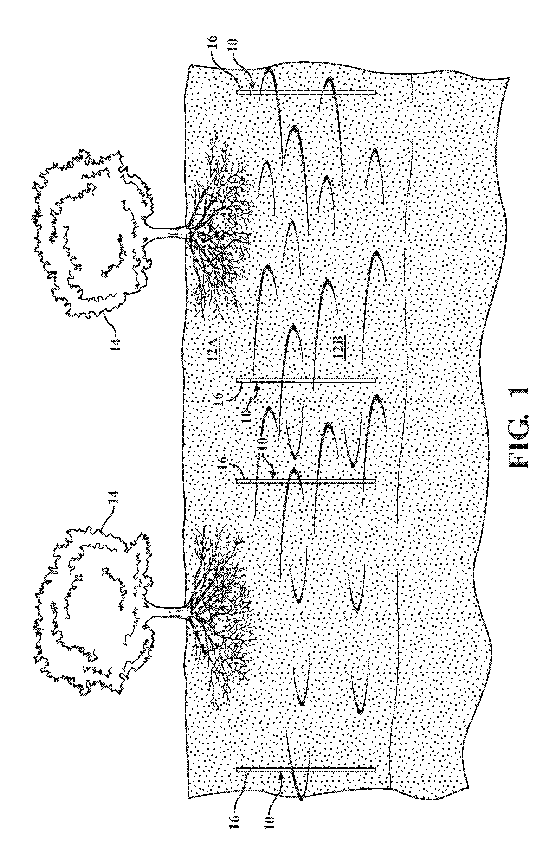
[0014] FIG. 1 is a view of a soil section having roots of trees growing therein with an array of vent members installed in a vertical orientation in the soil at a depth well below the root zone, the upper end of each vent member having a cap assembled thereon and extending up into the root zone.
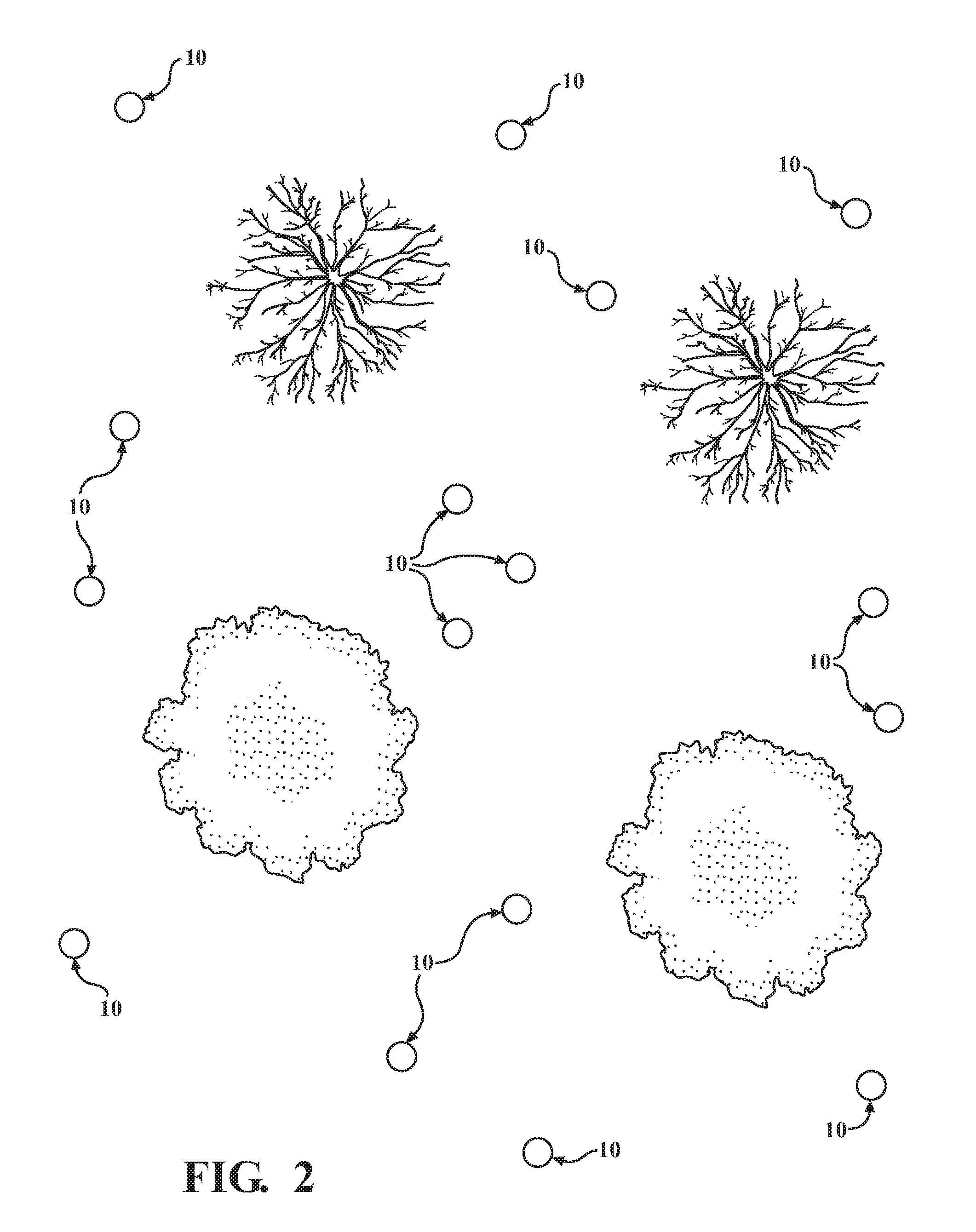
[0015] FIG. 2 is a plan view of a group of trees depicting an array of vent members each with a respective cap on the upper end thereof disposed around the roots of the trees.
[0016] FIGS. 3A and 3B are perspective views from two different angles of a vent member according to the present invention, with the vent member shown truncated.
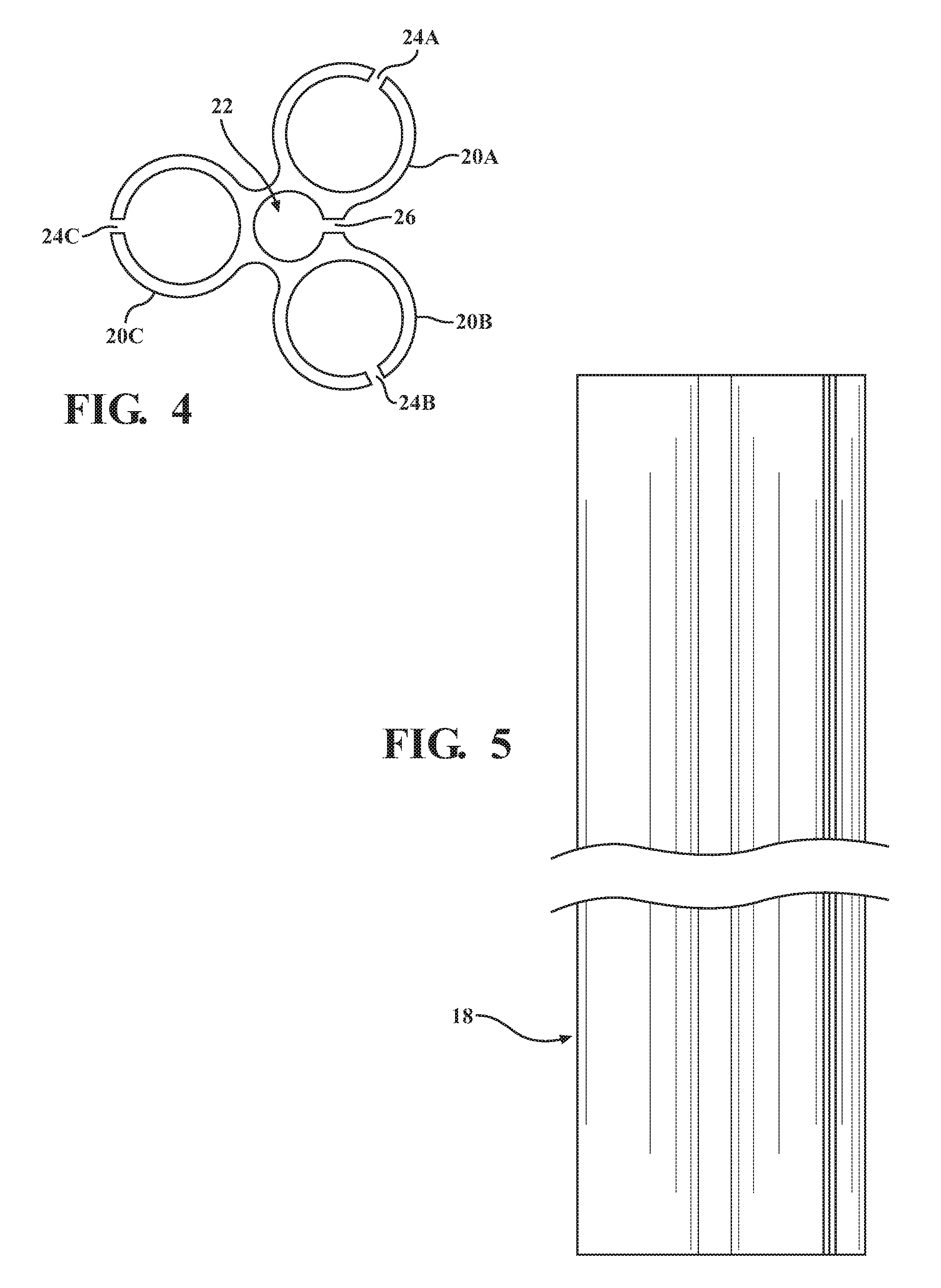
[0017] FIG. 4 is an enlarged end view of a vent member.
[0018] FIG. 5 is a side elevational view of the vent member shown in FIG. 4, shown broken at an intermediate point along the length thereof.
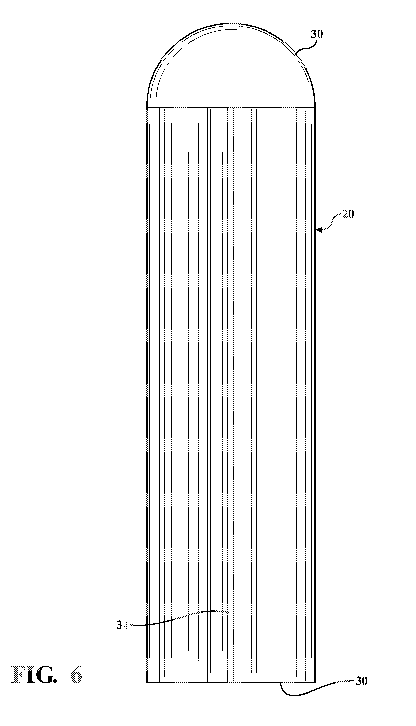
[0019] FIG. 6 is a side elevational view of a cap installed on the upper end of each vent member.
[0020] FIG. 7 is an end view from the bottom of the cap shown in FIG. 6.
[0021] FIG. 8 is an enlarged portion of the bottom end view of the cap shown in FIG. 7.
[0022] FIG. 9 is a lengthwise sectional view of the cap shown in FIGS. 6-8.
DETAILED DESCRIPTION
[0023] In the following detailed description, certain specific terminology will be employed for the sake of clarity and a particular embodiment described in accordance with the requirements of 35 USC 112, but it is to be understood that the same is not intended to be limiting and should not be so construed inasmuch as the invention is capable of taking many forms and variations within the scope of the appended claims.
[0024] Referring to FIG. 1, the present invention includes vertically oriented elongated vent members 10 which are installed in holes drilled in the subsoil below the root zone 12A of a group of trees 14.
[0025] The vent members 10 are of a length sufficient to extend well down below the root zone 12A into a virgin subsoil region 12B. However, the upper end 16 of each of the vent members 10 extends into the root zone 12A.
[0026] As seen in FIGS. 1 and 2, the vertically oriented vent members 10 are located disposed around the perimeter of the roots of the trees 14.
[0027] Referring to FIGS. 3A and 3B, each of the vent members 10 includes an elongated tubular collector 18 which is of a length sufficient to extend deep into the subsoil 12B below the root zone 12A and caps 20 are installed on the upper ends of collector portions 18. The portions 18 are shown truncated in FIGS. 3A, 3B.
[0028] FIGS. 4 and 5 show the configuration of the tubular collectors 18, which includes three outer tube portions 20A, 20B, 20c which are connected integrally with each other and symmetrically arranged around a smaller diameter central tube portion 22 also integrally formed with the outer tube portions 20A, 20B, 20C.
[0029] Each of the outer tubes 20A, 20B, and 20C has a full length extending slot 24A, 24B, 24C at its outermost side so as to be exposed to the surrounding subsoil 12B. The smaller center tube 22 also has a full length slot 26 arranged between two of the outer tubes 20A, 20B so as to also be exposed to the surrounding subsoil 12B.
[0030] The presence of the slots 24A, 24B, 24C and 26 allow gaseous fluids and/or vapors captured in the surrounding subsoil 12B to pass into the interior of the outer tube portions 20A, 20B, 20C and center tube portion 24 to collect gases and/or vapors which subsequently rise up the same due to a mildly pressurized condition of these fluids.
[0031] Trace elements may be dissolved, entrained or otherwise contained in the gaseous fluid which typically is somewhat pressurized and thus rises up to pass into the interior of the cap 20.
[0032] FIGS. 6-8 show details of the cap 20.
[0033] The cap 20 has an interior space 28 into which the collected gases/vapors, which is completely closed off from the exterior of the cap 20, being sealed by a cap cover 30 fused to the upper end of the cap 20 to capture the fluids flowing out of the ends of the tube portions 20A, 20B, 20C and 22 so that a corresponding pressure builds up therein.
[0034] This causes the fluids to be pass out of the cap interior space disposed between the lower end 30 of the cap 20 and the exterior of the associated tubular collector 18, and thereafter rises into the open lower ends of four outer spaces 32 which extend up on the outside of the cap 20. From there, the gaseous fluid rises up through the spaces 32, passing out of the slots 34 and into the soil 12A around the cap 20 to thereby be dispersed into the root zone soil 12A.
[0035] Accordingly, trace elements are thereby restored to the soil in the root zone 12A to be available to be absorbed by the roots of the trees 14. This has been found to significantly increase the vigor and growth rate of the trees 14.
* * * * *
D00000
D00001
D00002
D00003
D00004
D00005
D00006
D00007
XML
uspto.report is an independent third-party trademark research tool that is not affiliated, endorsed, or sponsored by the United States Patent and Trademark Office (USPTO) or any other governmental organization. The information provided by uspto.report is based on publicly available data at the time of writing and is intended for informational purposes only.
While we strive to provide accurate and up-to-date information, we do not guarantee the accuracy, completeness, reliability, or suitability of the information displayed on this site. The use of this site is at your own risk. Any reliance you place on such information is therefore strictly at your own risk.
All official trademark data, including owner information, should be verified by visiting the official USPTO website at www.uspto.gov. This site is not intended to replace professional legal advice and should not be used as a substitute for consulting with a legal professional who is knowledgeable about trademark law.