Storage Cover Plate And Storage Chassis Using The Same
CHEN; YUXIN ; et al.
U.S. patent application number 16/234863 was filed with the patent office on 2019-07-04 for storage cover plate and storage chassis using the same. This patent application is currently assigned to CELESTICA TECHNOLOGY CONSULTANCY (SHANGHAI) CO. LTD. The applicant listed for this patent is CELESTICA TECHNOLOGY CONSULTANCY (SHANGHAI) CO. LTD. Invention is credited to YUXIN CHEN, WENJIN LI, YU WANG.
| Application Number | 20190208657 16/234863 |
| Document ID | / |
| Family ID | 67058690 |
| Filed Date | 2019-07-04 |

| United States Patent Application | 20190208657 |
| Kind Code | A1 |
| CHEN; YUXIN ; et al. | July 4, 2019 |
STORAGE COVER PLATE AND STORAGE CHASSIS USING THE SAME
Abstract
The present disclosure provides a storage cover plate and a storage chassis using the same. The storage cover plate is covered on a storage chassis for accommodating a plurality of storages, wherein the storage cover plate comprises a plurality of closely arranged sub-covers, the plurality of closely arranged sub-covers each corresponds to a row of storages respectively, the plurality of the sub-covers each is capable of sliding along edges of the storage chassis, and the outermost sub-cover is locked with the storage chassis through a locking part. If one of storages needs to be operated, an unlocking operation is performed first and then the sub-cover above the storage is pushed, so that the storage below the sub-cover can be operated directly. The present disclosure is easy to install and convenient to assemble, disassemble and maintain, therefore achieving high economical efficacy and practicability.
| Inventors: | CHEN; YUXIN; (SHANGHAI, CN) ; WANG; YU; (SHANGHAI, CN) ; LI; WENJIN; (SHANGHAI, CN) | ||||||||||
| Applicant: |
|
||||||||||
|---|---|---|---|---|---|---|---|---|---|---|---|
| Assignee: | CELESTICA TECHNOLOGY CONSULTANCY
(SHANGHAI) CO. LTD SHANGHAI CN |
||||||||||
| Family ID: | 67058690 | ||||||||||
| Appl. No.: | 16/234863 | ||||||||||
| Filed: | December 28, 2018 |
| Current U.S. Class: | 1/1 |
| Current CPC Class: | G11B 33/00 20130101; G06F 1/181 20130101; G11B 33/127 20130101; H05K 5/0286 20130101; G06F 1/187 20130101 |
| International Class: | H05K 5/02 20060101 H05K005/02 |
Foreign Application Data
| Date | Code | Application Number |
|---|---|---|
| Dec 29, 2017 | CN | 2017114766096 |
| Dec 29, 2017 | CN | 2017219020754 |
Claims
1. A storage cover plate, covered on a storage chassis for accommodating a plurality of storages, wherein the storage cover plate comprises a plurality of closely arranged sub-covers, the plurality of closely arranged sub-covers each corresponds to a row of storages respectively, the plurality of the sub-covers each is capable of sliding along edges of the storage chassis, and the outermost sub-cover is locked with the storage chassis through a locking part.
2. The storage cover plate according to claim 1, wherein the sub-cover has a width matching with the width of each row of storage.
3. The storage cover plate according to claim 1, wherein the locking part comprises slots provided on the edges of the storage chassis and hooks provided on both sides of the sub-cover.
4. The storage cover plate according to claim 1, wherein two locking parts are provided, which are installed on both sides of the outermost sub-cover.
5. A storage chassis, used for accommodating a plurality of storages, wherein the storage chassis comprises the storage cover plate according to claim 1 covered on the storage chassis.
Description
CROSS REFERENCES TO RELATED APPLICATIONS
[0001] This application claims the benefits of priority to Chinese Patent Application No. CN2017114766096, entitled "Storage Cover Plate and Storage Chassis Using the Same", filed with the Chinese Patent Office on Dec. 29, 2017, and Chinese Patent Application No. CN2017219020754, entitled "Storage Cover Plate and Storage Chassis Using the Same", filed with the Chinese Patent Office on Dec. 29, 2017, the contents of which are incorporated herein by reference in its entirety.
BACKGROUND OF THE PRESENT INVENTION
Field of Invention
[0002] The present disclosure relates to technical filed of electronic device, and in particular, to a storage cover plate and a storage chassis using the same.
Description of Related Arts
[0003] An electronic device such as a portable computer has a storage chassis for accommodating storages. The storage chassis is located in a housing of the device. The storage chassis is provided with an opening in the bottom of the housing. The opening is used for inserting the storage module into the storage chassis and detaching the storage module from the storage chassis. The opening is closed by a cover.
[0004] A regular cover is flat, such as a plate, and the outer periphery of the cover fits with the chassis of the housing.
[0005] The large-capacity storage device includes a large number of storages, the storages need to be replaced or perform other operations frequently. Therefore, operations on the storages are required to be easy and convenient.
SUMMARY OF THE PRESENT INVENTION
[0006] In view of the foregoing disadvantage of the prior art, an object of the present application is to provide a storage cover plate and a storage chassis using the same, so as to resolve the problem in the prior art that due to the cover plate, a storage cannot be replaced or operated rapidly when a storage chassis accommodates a large number of storages.
[0007] In order to accomplish the above and other related objects, the present application provides a storage cover plate covered on a storage chassis for accommodating a plurality of storages, wherein the storage cover plate comprises a plurality of closely arranged sub-covers, the plurality of closely arranged sub-covers each corresponds to a row of storages respectively, the plurality of the sub-covers each is capable of sliding along edges of the storage chassis, and the outermost sub-cover is locked with the storage chassis through a locking part.
[0008] In an embodiment of the present application, the sub-cover has a width matching with the width of each row of storage.
[0009] In an embodiment of the present application, the locking part comprises slots provided on the edges of the storage chassis and hooks provided on both sides of the sub-cover.
[0010] In an embodiment of the present application, two locking parts are provided, which are installed on both sides of the outermost sub-cover.
[0011] An embodiment of the present application further provides a storage chassis, which is used for accommodating multiple storages and comprises the aforementioned storage cover plate covered on the storage chassis.
[0012] As described above, the storage cover plate according to the present disclosure comprises a plurality of closely arranged sub-covers each corresponds to a row of storages respectively, where the plurality of sub-covers are capable of sliding along edges of the storage chassis, and the outermost sub-cover is locked with the storage chassis through a locking part. If a particular storage needs to be operated, an unlocking operation is performed first and then the sub-cover above the storage is pushed, so that the storage below the sub-cover can be operated directly. The present application is easy to install and convenient to assemble, disassemble and maintain, therefore achieving high economical efficacy and practicability.
BRIEF DESCRIPTION OF THE DRAWINGS
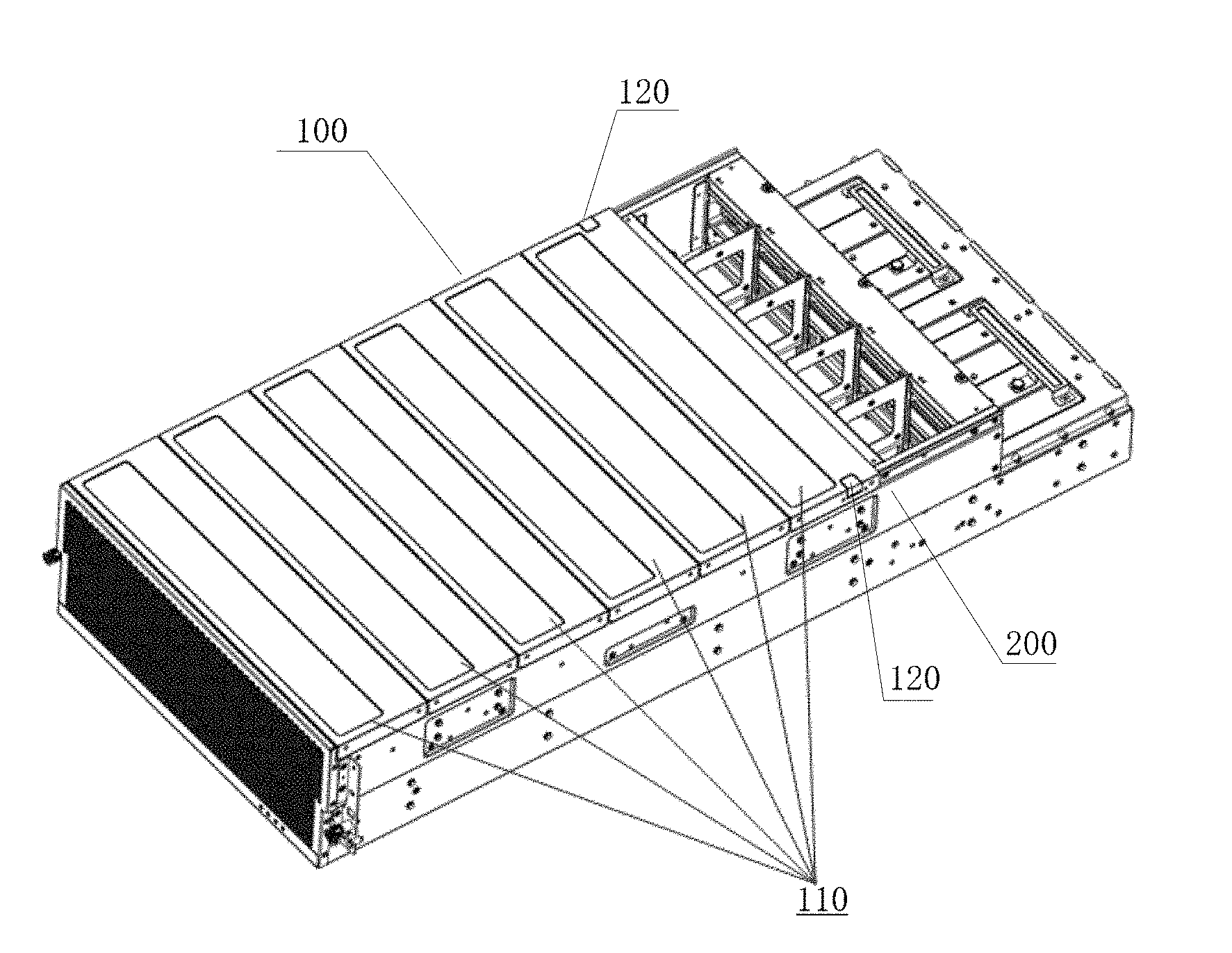
[0013] FIG. 1 is a schematic diagram when the storage cover plate according to the present disclosure is covered on a storage chassis.
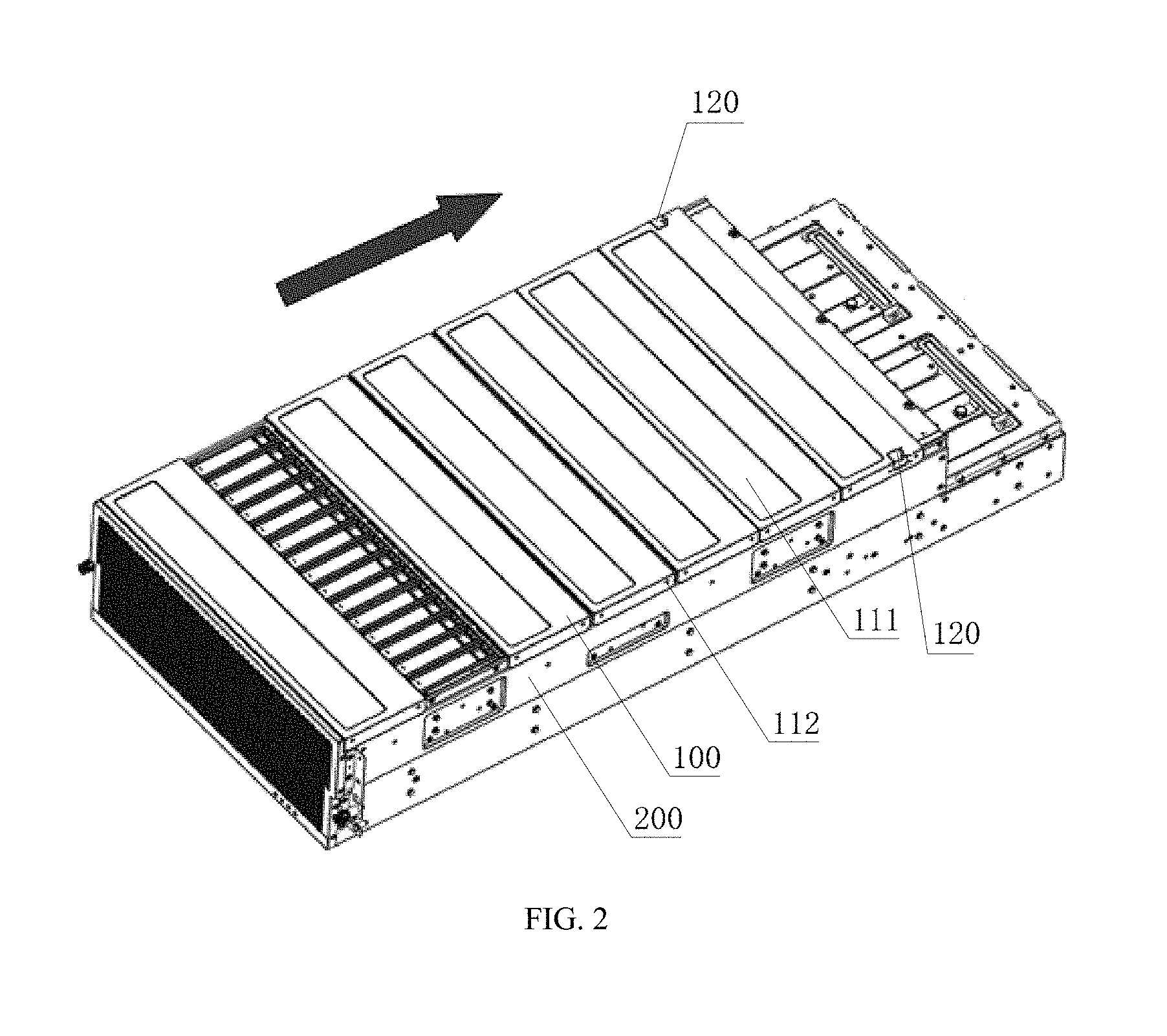
[0014] FIG. 2 is a schematic diagram of a storage cover plate according to the present disclosure when one of the sub-covers is pushed.
TABLE-US-00001 Descriptions of component mark numbers 100 Storage cover plate 110 Sub-cover 111 Groove 112 Vent hole or connection hole 120 Locking part 200 Storage chassis
DETAILED DESCRIPTION OF THE PREFERRED EMBODIMENTS
[0015] Implementations of the present disclosure are illustrated below through specific embodiments. A person skilled in the art can easily understand other advantages and efficacy of the present disclosure according to the content disclosed in this specification. The present disclosure can also be implemented or applied through other different specific implementations. Various modifications or variations can also be made on details in this specification based on different opinions and applications without departing from the spirit of the present disclosure.
[0016] It should be noted that, the figures provided in this embodiment merely illustrate the basic conception of the present disclosure schematically. Therefore, the figures only show components related to the present disclosure, and are not drawn according to the quantity, shapes and sizes of components during actual implementation. The pattern, quantity and ratio of components during actual implementation can be changed arbitrarily, and the component layout may also be more complex.
[0017] This embodiment provides a storage cover plate, so as to resolve the problems in the prior art that assembly and disassembly of a hard-disk cartridge are complex, and that a hard disk is easily damaged when the hard disk is plugged for multiple times. A storage cover plate according to this embodiment and a storage chassis using the same will be described in detail in the following, so that a person skilled in the art can understand the storage cover plate according to this embodiment and the storage chassis using the same without making creative efforts.
[0018] FIG. 1 and FIG. 2 are schematic diagrams of a storage cover plate 100 according to the present disclosure in a specific embodiment.
[0019] As shown in FIG. 1, this embodiment provides a storage cover plate 100 covered on a storage chassis 200, the storage chassis 200 accommodates a plurality of storages. The storage cover plate 100 comprises a plurality of closely arranged sub-covers 110, the plurality of the sub-covers each corresponds to a row of the storages respectively. For example, five storages are configured in the storage chassis 200, the storage cover plate 100 includes five closely arranged sub-covers 110, each of the sub-covers corresponds to one of the five storages respectively.
[0020] As shown in FIG. 2, the sub-covers 110 are capable of sliding along edges of the storage chassis 200. The outermost sub-cover 110 of is locked with the storage chassis 200 through a locking part 120.
[0021] As shown in FIG. 2, the plurality of the sub-covers 110 each is capable of sliding along the edges of the storage chassis 200. If a storage needs to be operated, unlocking the locking part 120, then pushing the sub-cover 110 corresponding to the storage, all the sub-covers 110 behind the sub-cover 110 can be driven to slide along the pushing direction, so that the pushed sub-cover 110 is moved away from the surface of the corresponding storage, thereby achieving the object of operating the storage.
[0022] For example, as shown in FIG. 2, if an operation needed to be performed is on the second row, unlocking the storage cover plate 100, then pushing the sub-cover 110 corresponding to the second-row storage, so that the operation is performed.
[0023] In this embodiment, the sub-cover 110 has a width matching with the width of each row of storage covered.
[0024] Specifically, in this embodiment, the sub-cover 110 comprises a panel and side plates connected to ends of the panel in a bent manner. The side plate is provided with a vent hole or a connection hole. The sub-cover 110 may be provided with a groove 111 on its surface as required.
[0025] Specifically, in this embodiment, the locking part 120 comprises, but is not limited to, slots provided on the edges of the storage chassis 200 and hooks provided on the surface of the sub-cover 110, so that the storage cover plate 100 can be locked and unlocked without using other unlocking tools. In another embodiment, the locking part 120 may be other locking forms, which is not limited to the slot-hook locking form.
[0026] In this embodiment, two locking parts 120 are provided, which are installed on two sides of the outermost sub-cover 110. In this embodiment, the sub-cover 110 is designed to achieve the purpose of independently controlling operations on each row of storage. Besides, the storage cover plate 100 can be unlocked and secured without using any tool, so that the operation is easy and convenient.
[0027] In addition, this embodiment further provides a storage chassis. The storage chassis accommodates a plurality of storages and comprises the aforementioned storage cover plate 100 covered on the storage chassis 200. The storage cover plate 100 has been described in detail above, and is not described in detail herein again.
[0028] In conclusion, the storage cover plate according to the present disclosure comprises a plurality of closely arranged sub-covers each corresponds to a row of storages respectively, where the plurality of sub-covers are capable of sliding along edges of the storage chassis, and the outermost sub-cover is locked with the storage chassis through a locking part. If a particular storage needs to be operated, an unlocking operation is performed first and then the sub-cover above the storage is pushed, so that the storage below the sub-cover can be operated directly. The present disclosure is easy to install and convenient to assemble, disassemble and maintain, therefore achieving high economical efficacy and practicability. Therefore, the present disclosure effectively overcomes various disadvantages in the prior art and hence has high industrial use value.
[0029] The foregoing embodiments are only to illustrate the principle and efficacy of the present disclosure exemplarily, and are not to limit the present disclosure. Any person skilled in the art can make modifications or variations on the foregoing embodiments without departing from the spirit and scope of the present disclosure. Accordingly, all equivalent modifications or variations completed by a person of ordinary skill in the art without departing from the spirit and technical thinking disclosed by the present disclosure should fall within the scope of claims of the present disclosure.
* * * * *
D00000
D00001
D00002
XML
uspto.report is an independent third-party trademark research tool that is not affiliated, endorsed, or sponsored by the United States Patent and Trademark Office (USPTO) or any other governmental organization. The information provided by uspto.report is based on publicly available data at the time of writing and is intended for informational purposes only.
While we strive to provide accurate and up-to-date information, we do not guarantee the accuracy, completeness, reliability, or suitability of the information displayed on this site. The use of this site is at your own risk. Any reliance you place on such information is therefore strictly at your own risk.
All official trademark data, including owner information, should be verified by visiting the official USPTO website at www.uspto.gov. This site is not intended to replace professional legal advice and should not be used as a substitute for consulting with a legal professional who is knowledgeable about trademark law.