Methods And Apparatus For Exploiting Interfaces Smart Environment Device Application Program Interfaces
Kortz; Samuel W. ; et al.
U.S. patent application number 16/293358 was filed with the patent office on 2019-07-04 for methods and apparatus for exploiting interfaces smart environment device application program interfaces. This patent application is currently assigned to Google LLC. The applicant listed for this patent is Google LLC. Invention is credited to Gregory J. Hu, Samuel W. Kortz, Mark McBride, Amanda Surya.
| Application Number | 20190208390 16/293358 |
| Document ID | / |
| Family ID | 54869564 |
| Filed Date | 2019-07-04 |

View All Diagrams
| United States Patent Application | 20190208390 |
| Kind Code | A1 |
| Kortz; Samuel W. ; et al. | July 4, 2019 |
Methods And Apparatus For Exploiting Interfaces Smart Environment Device Application Program Interfaces
Abstract
A tangible, non-transitory, machine-readable medium, comprising instructions to obtain an estimated time of arrival for an occupant of a household; calculate a transition time to reach a desired temperature of the occupant from a current ambient temperature within the household; if, the estimated time of arrival is less than or equal to the transition time, activate a transition to the desired temperature; otherwise if the estimated time of arrival is greater than the transition time, do not activate the transition.
| Inventors: | Kortz; Samuel W.; (Palo Alto, CA) ; Hu; Gregory J.; (Los Altos, CA) ; Surya; Amanda; (Santa Clara, CA) ; McBride; Mark; (Santa Clara, CA) | ||||||||||
| Applicant: |
|
||||||||||
|---|---|---|---|---|---|---|---|---|---|---|---|
| Assignee: | Google LLC Mountain View CA |
||||||||||
| Family ID: | 54869564 | ||||||||||
| Appl. No.: | 16/293358 | ||||||||||
| Filed: | March 5, 2019 |
Related U.S. Patent Documents
| Application Number | Filing Date | Patent Number | ||
|---|---|---|---|---|
| 14577635 | Dec 19, 2014 | |||
| 16293358 | ||||
| 62016052 | Jun 23, 2014 | |||
| Current U.S. Class: | 1/1 |
| Current CPC Class: | G06F 9/546 20130101; H04L 67/12 20130101; H04L 63/08 20130101; F24F 11/30 20180101; H04L 12/2818 20130101; H04L 12/2829 20130101; H04W 4/60 20180201; G05D 23/1904 20130101; H04W 4/80 20180201; H04L 12/282 20130101; G05B 17/02 20130101; H05B 47/105 20200101; G05B 15/02 20130101; H04L 12/2816 20130101; H04L 12/2823 20130101; H04L 12/2803 20130101; H04L 67/30 20130101; H04W 4/021 20130101; G08B 17/10 20130101; H04L 29/06047 20130101; G05D 23/1917 20130101; G06F 9/541 20130101; H04L 67/22 20130101; F24F 11/62 20180101; H04L 2012/2841 20130101; G06F 9/54 20130101; H04L 67/42 20130101; G05B 13/04 20130101; H04L 2012/285 20130101; H04L 67/1097 20130101; H04M 1/72533 20130101; G05B 2219/2642 20130101; H05B 47/19 20200101 |
| International Class: | H04W 4/80 20060101 H04W004/80; G05B 15/02 20060101 G05B015/02; H04L 12/28 20060101 H04L012/28; G05D 23/19 20060101 G05D023/19; G05B 13/04 20060101 G05B013/04; H04L 29/08 20060101 H04L029/08; H05B 37/02 20060101 H05B037/02; F24F 11/30 20060101 F24F011/30; G05B 17/02 20060101 G05B017/02; H04W 4/021 20060101 H04W004/021; F24F 11/62 20060101 F24F011/62; H04L 29/06 20060101 H04L029/06; H04M 1/725 20060101 H04M001/725; H04W 4/60 20060101 H04W004/60; G08B 17/10 20060101 G08B017/10; G06F 9/54 20060101 G06F009/54 |
Claims
1. (canceled)
2. A method for controlling a smart-home lighting device, the method comprising: receiving, by an application, an audible cue from a user that corresponds to a command to control the smart-home lighting device; converting the audible cue into a device request message to command the smart-home lighting device; forwarding the device request message to an application programming interface (API) server that is effective to cause the API server to: update a data model based on the device request message; and send the command to the smart-home lighting device via an update signal communicated to the smart-home lighting device that causes the smart-home lighting device to perform an action.
3. The method of claim 2, comprising: receiving, by the application, one or more device status parameters of the smart-home lighting device via an API of the API server.
4. The method of claim 2, wherein the data model comprises information related to one or more smart-home devices including the smart-home lighting device, one or more smart-device environment structures comprising the smart-devices, or both.
5. The method of claim 2, wherein the audible cue sets a value of a parameter of the smart-home lighting device.
6. The method of claim 5, wherein the parameter of the smart home lighting device is one of: a light setting, a dim state of one or more lights, activating lighting, deactivating lighting, or a lighting color.
7. The method of claim 2, wherein the audible cue sets an operational mode of the smart-home lighting device.
8. The method of claim 7, wherein the operation mode is an occupancy mode, and wherein the occupancy mode comprises a home mode and an away mode.
9. The method of claim 2, comprising receiving, by the application, an indication of crossing a geo-fence boundary that corresponds to another command to control the smart-home lighting device; converting the indication of crossing a geo-fence boundary into another device request message to command the smart-home lighting device; forwarding the other device request message to the application programming interface (API) server that is effective to cause the API server to: update the data model based on the other device request message; and send the other command to the smart-home lighting device via another update signal communicated to the smart-home lighting device that causes the smart-home lighting device to perform another action.
10. A system comprising: an application programming interface (API) server; and an electronic device configured to: receive an audible cue from a user that corresponds to a command to control a smart-home lighting device; convert the audible cue into a device request message to command the smart-home lighting device; and forward the device request message to the API server that is effective to cause the API server to: update a data model based on the device request message; and send the command to the smart-home lighting device via an update signal communicated to the smart-home lighting device that causes the smart-home lighting device to perform an action.
11. The system of claim 10, the electronic device configured to: receive one or more device status parameters of the smart-home lighting device via an API of the API server.
12. The system of claim 10, wherein the data model comprises information related to one or more smart-home devices including the smart-home lighting device, one or more smart-device environment structures comprising the smart-devices, or both.
13. The system of claim 10, wherein the audible cue sets a value of a parameter of the smart-home lighting device.
14. The system of claim 10, wherein the audible cue sets an operational mode of the smart-home lighting device.
15. The system of claim 14, wherein the operation mode is an occupancy mode, and wherein the occupancy mode comprises a home mode and an away mode.
16. One or more non-transitory, computer-readable media comprising instructions to: receive an audible cue from a user that corresponds to a command to control a smart-home lighting device; convert the audible cue into a device request message to command the smart-home lighting device; and forward the device request message to an application programming interface (API) server that is effective to cause the API server to: update a data model based on the device request message; and send the command to the smart-home lighting device via an update signal communicated to the smart-home lighting device that causes the smart-home lighting device to perform an action.
17. The one or more non-transitory, computer-readable media of claim 16, comprising instructions to receive one or more device status parameters of the smart-home device via an API of the API server.
18. The one or more non-transitory, computer-readable media of claim 16, wherein the data model comprises information related to one or more smart-home devices including the smart-home lighting device, one or more smart-device environment structures comprising the smart-devices, or both.
19. The one or more non-transitory, computer-readable media of claim 16, wherein the audible cue sets a value of a parameter of the smart-home lighting device.
20. The one or more non-transitory, computer-readable media of claim 19, wherein the parameter of the smart home lighting device is one of: a light setting, a dim state of one or more lights, activating lighting, deactivating lighting, or a lighting color.
21. The one or more non-transitory, computer-readable media of claim 16, wherein the audible cue sets an operational mode of the smart-home lighting device, wherein the operation mode is an occupancy mode, and wherein the occupancy mode comprises a home mode and an away mode.
Description
CROSS REFERENCE TO RELATED APPLICATIONS
[0001] This application is a Continuation Application of, and claims priority to, U.S. application Ser. No. 14/577,635, entitled "Methods And Apparatus For Exploiting Interfaces Smart Environment Device Application Program Interfaces", filed Dec. 19, 2014 which in turn claims priority to U.S. Provisional Patent Application No. 62/016,052, entitled "Methods and Apparatus for Exploiting Application Programming Interfaces to Smart Home Environment Electronic Components", filed Jun. 23, 2014, which is herein incorporated by reference.
BACKGROUND
[0002] This disclosure relates to controlling access to electronic devices via application programming interface (API) restrictions.
[0003] This section is intended to introduce the reader to various aspects of art that may be related to various aspects of the present disclosure, which are described and/or claimed below. This discussion is believed to be helpful in providing the reader with background information to facilitate a better understanding of the various aspects of the present disclosure. Accordingly, it should be understood that these statements are to be read in this light, and not as admissions of prior art.
[0004] People interact with a number of different electronic devices on a daily basis. In a home setting, for example, a person may interact with smart thermostats, lighting systems, alarm systems, entertainment systems, and a variety of other electronic devices. To interact with some of these electronic devices, a person may communicate a command using an application program running on another electronic device. For instance, a person may control the temperature setting on a smart thermostat using an application program running on a smartphone. The application program may communicate with a secure online service that interacts with that thermostat.
[0005] To preserve the user experience associated with an electronic device, the manufacturer of the electronic device may develop the application programs to control the electronic device. Opening access to the electronic devices to third party developers, however, may potentially improve the experience of some people with the devices--but only if third party application programs do not cause the electronic devices to behave in an undesirable manner. Accordingly, while it may be desirable to open access to the electronic devices to third party developers, it may also be desirable to place restrictions on that access so as to reduce the risk that the third party access may negatively impact the operation of the electronic devices and thus the user experience associated with those devices.
SUMMARY
[0006] A summary of certain embodiments disclosed herein is set forth below. It should be understood that these aspects are presented merely to provide the reader with a brief summary of these certain embodiments and that these aspects are not intended to limit the scope of this disclosure. Indeed, this disclosure may encompass a variety of aspects that may not be set forth below.
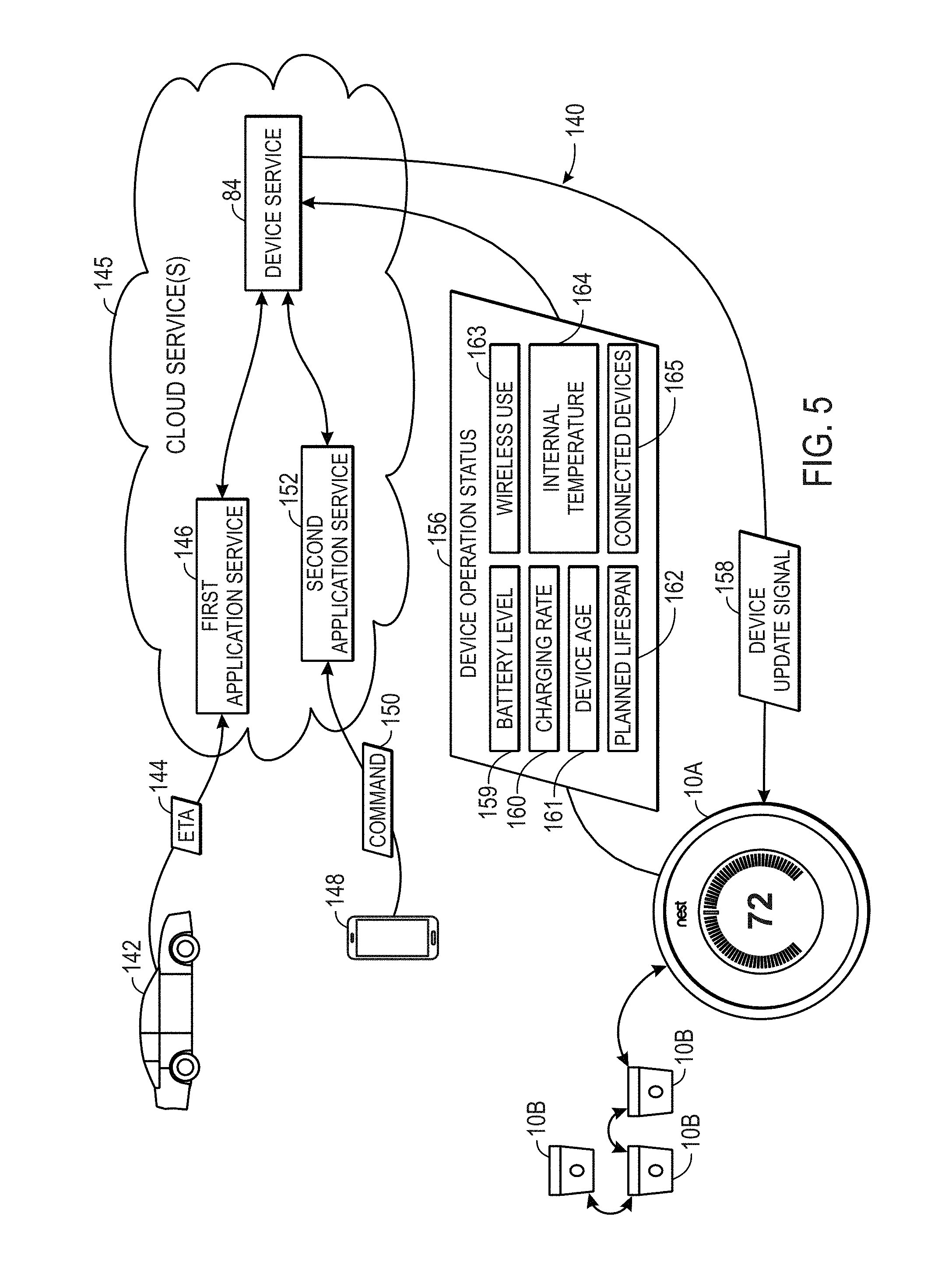
[0007] According to embodiments of this disclosure, applications may access different installations of smart home devices (e.g., via an application programming interface (API)). Namely, the third party applications may communicate not directly with a smart home device, but rather through a device service. The device service may provide a corresponding update signal to the target smart home device based on one or more factors such as operation status parameters of the device.
[0008] Various refinements of the features noted above may exist in relation to various aspects of the present disclosure. Further features may also be incorporated in these various aspects as well. These refinements and additional features may exist individually or in any combination. For instance, various features discussed below in relation to one or more of the illustrated embodiments may be incorporated into any of the above-described aspects of the present disclosure alone or in any combination. The brief summary presented above is intended only to familiarize the reader with certain aspects and contexts of embodiments of the present disclosure without limitation to the claimed subject matter.
BRIEF DESCRIPTION OF THE DRAWINGS
[0009] Various aspects of this disclosure may be better understood upon reading the following detailed description and upon reference to the drawings in which:
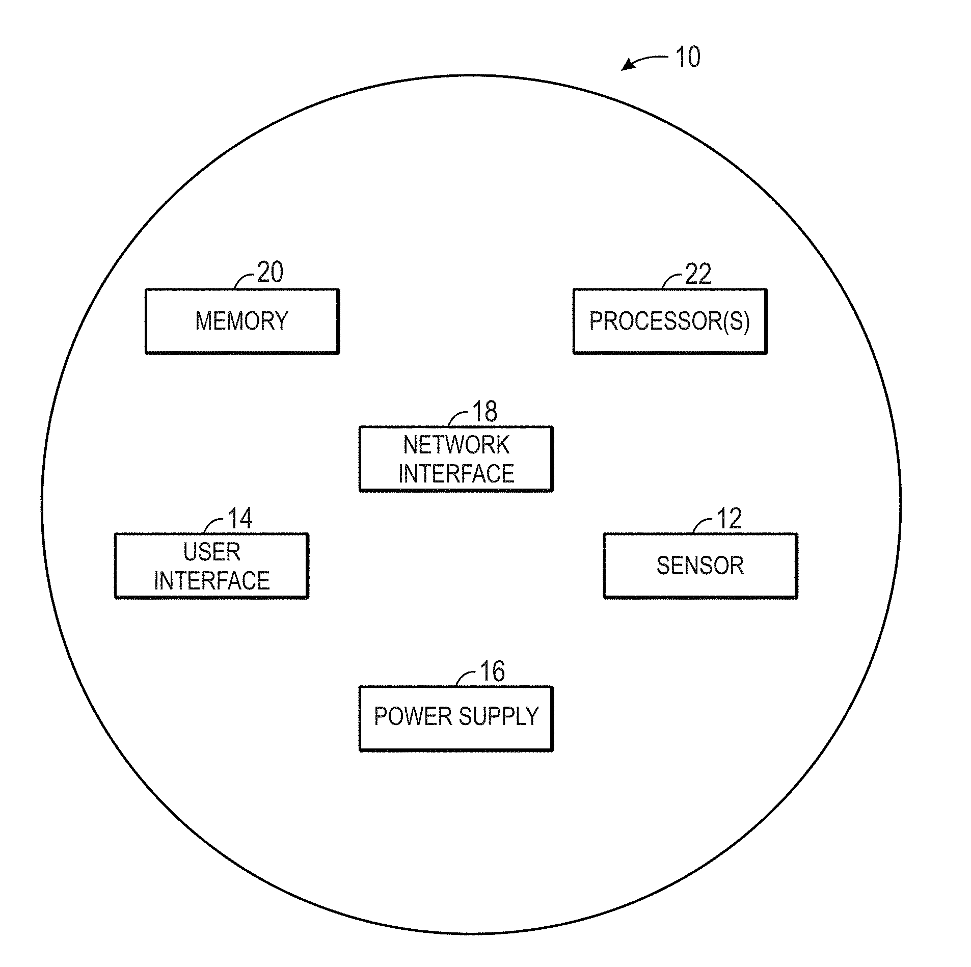
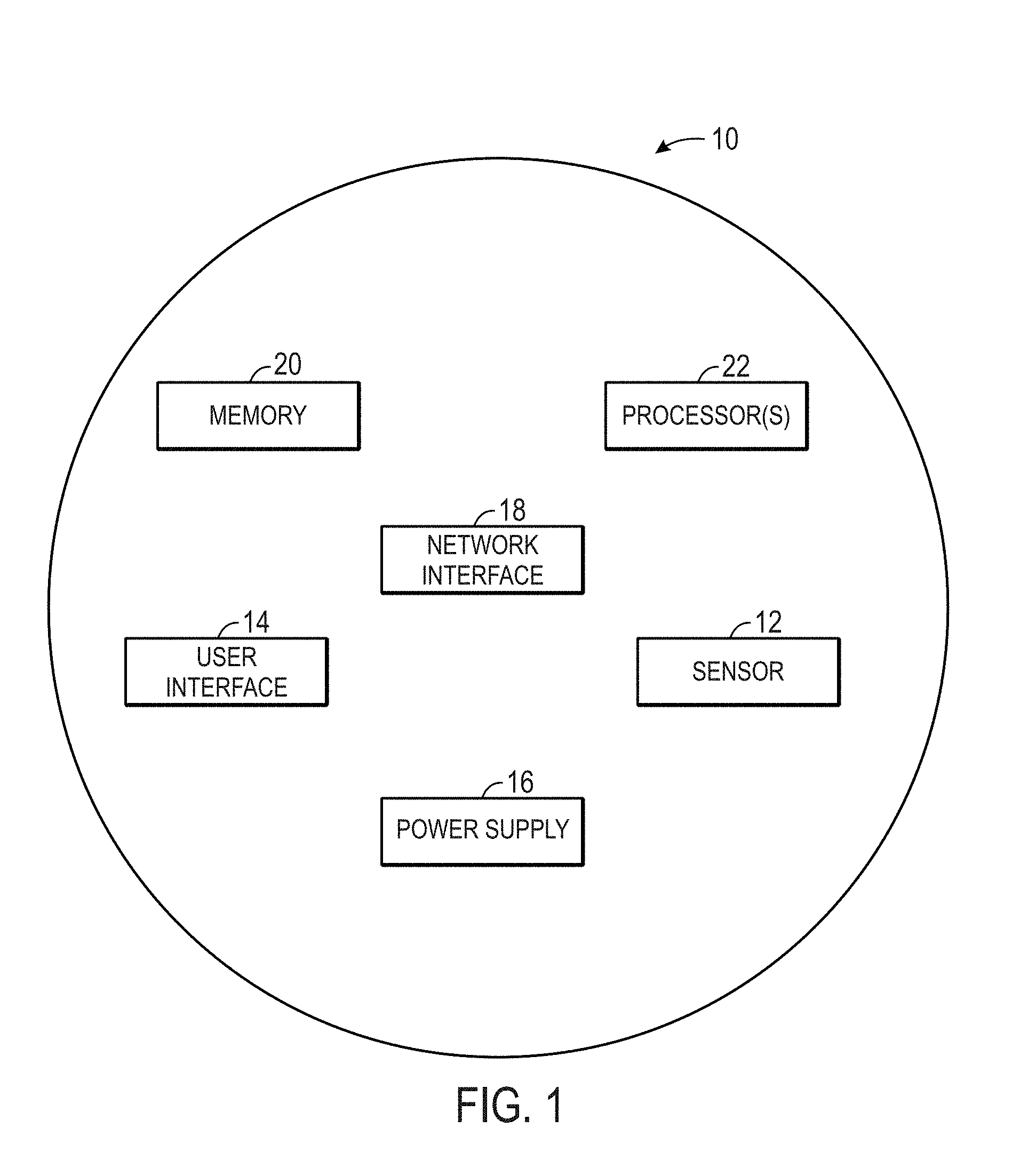
[0010] FIG. 1 is a block diagram of a smart home device, in accordance with an embodiment;
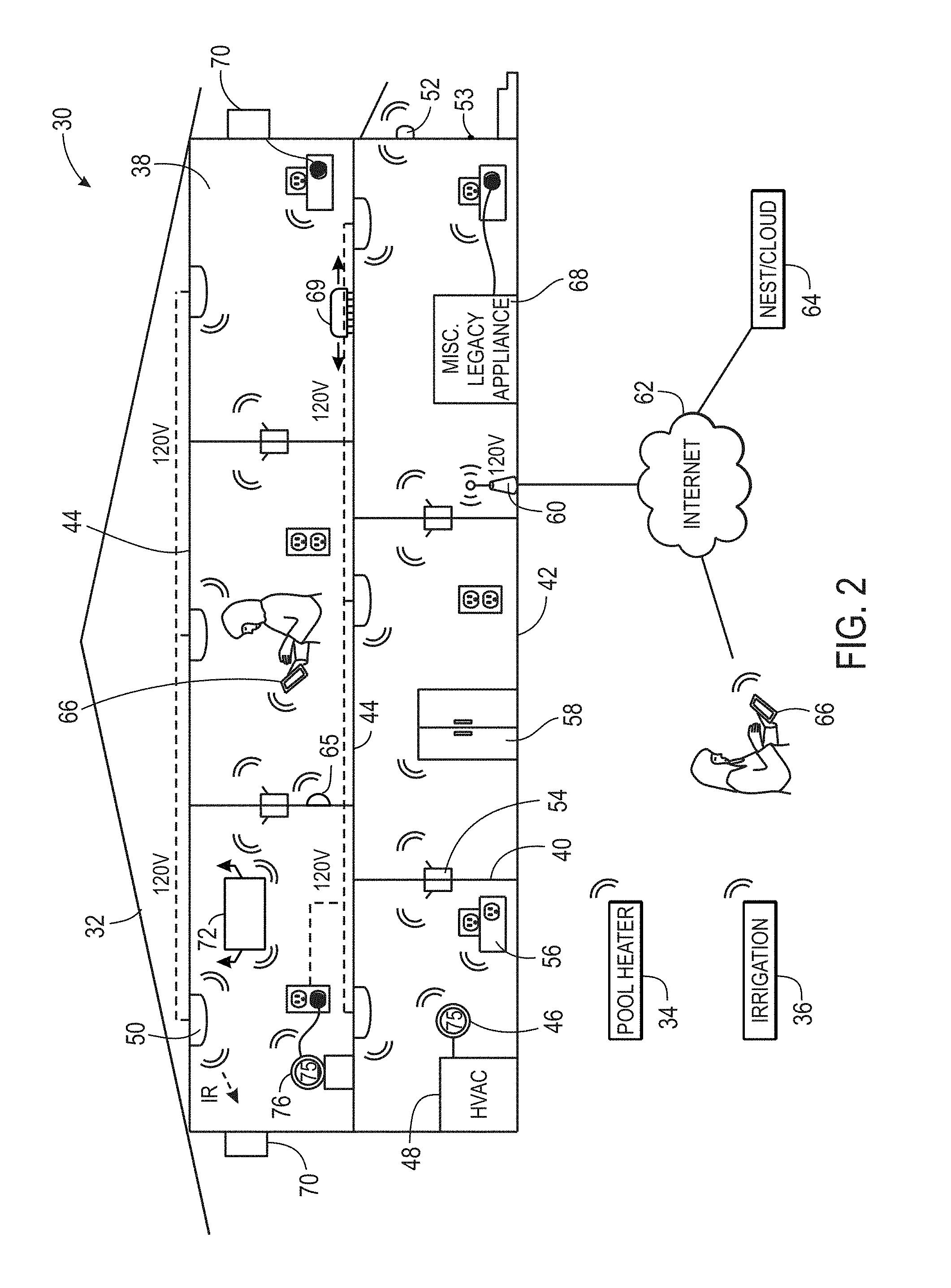
[0011] FIG. 2 is a block diagram of a connected smart home environment that includes a number of smart home devices, in accordance with an embodiment;
[0012] FIG. 3 is a block diagram illustrating a manner of controlling and/or accessing the smart home environment using services over the internet, in accordance with an embodiment;
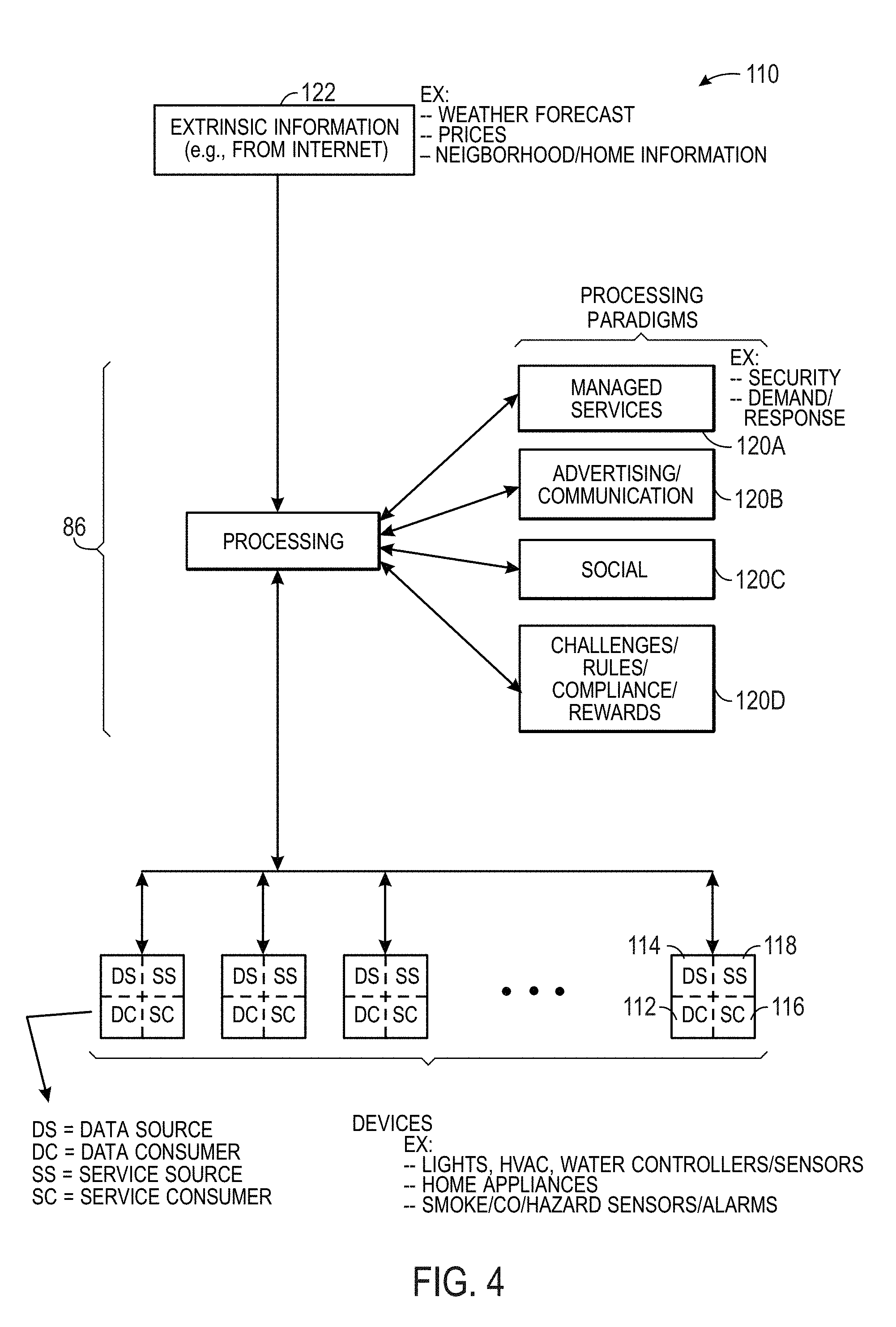
[0013] FIG. 4 is a block diagram of processing paradigms that may be used to control devices of the smart home environment, in accordance with an embodiment;
[0014] FIG. 5 is a block diagram of a system that provides access to smart home devices, in accordance with an embodiment;
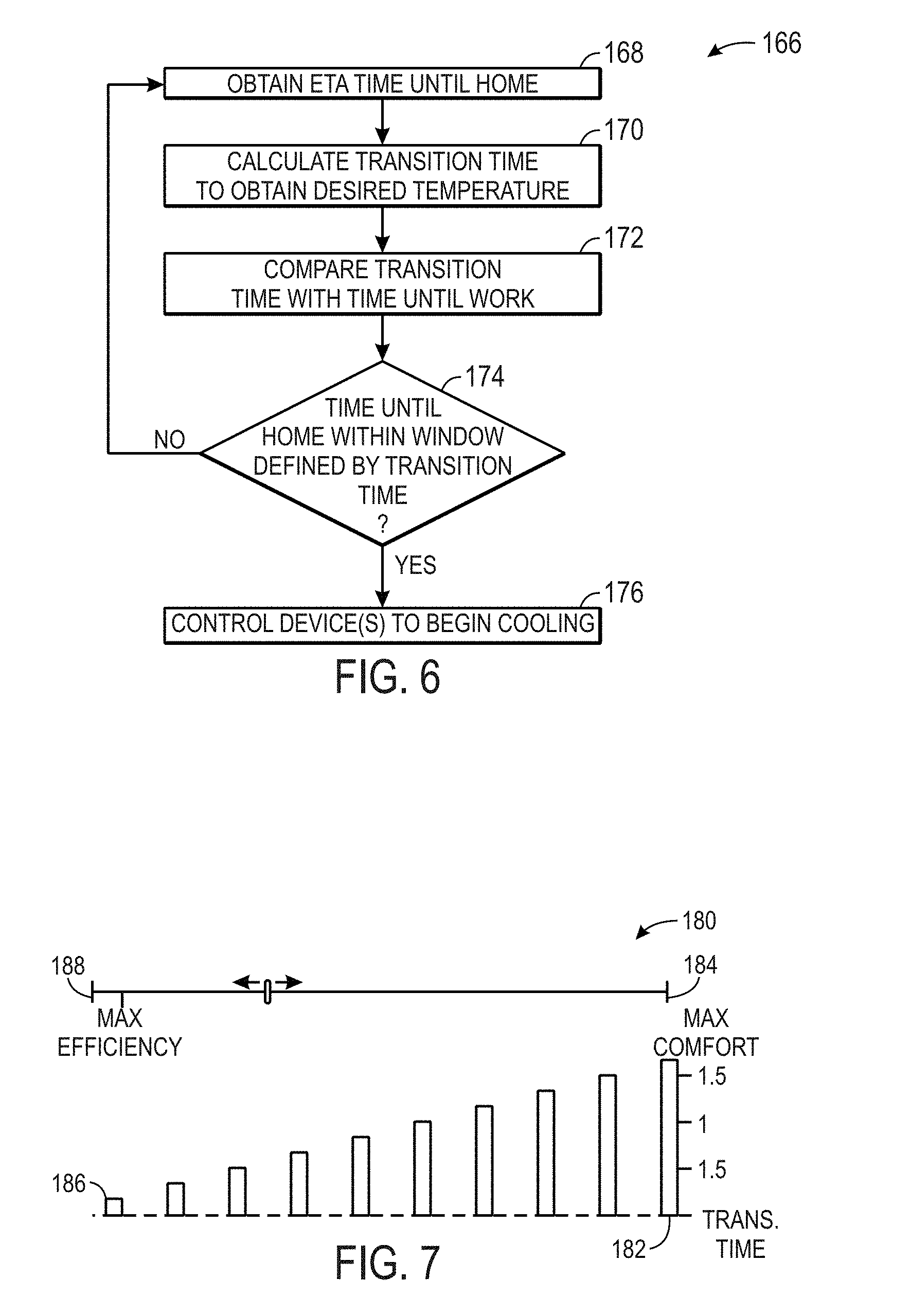
[0015] FIG. 6 is a flow diagram illustrating a method for transitioning temperatures based upon an estimated time of arrival, in accordance with an embodiment;
[0016] FIG. 7 is block diagram illustrating window creation for the method of FIG. 6, in accordance with an embodiment;
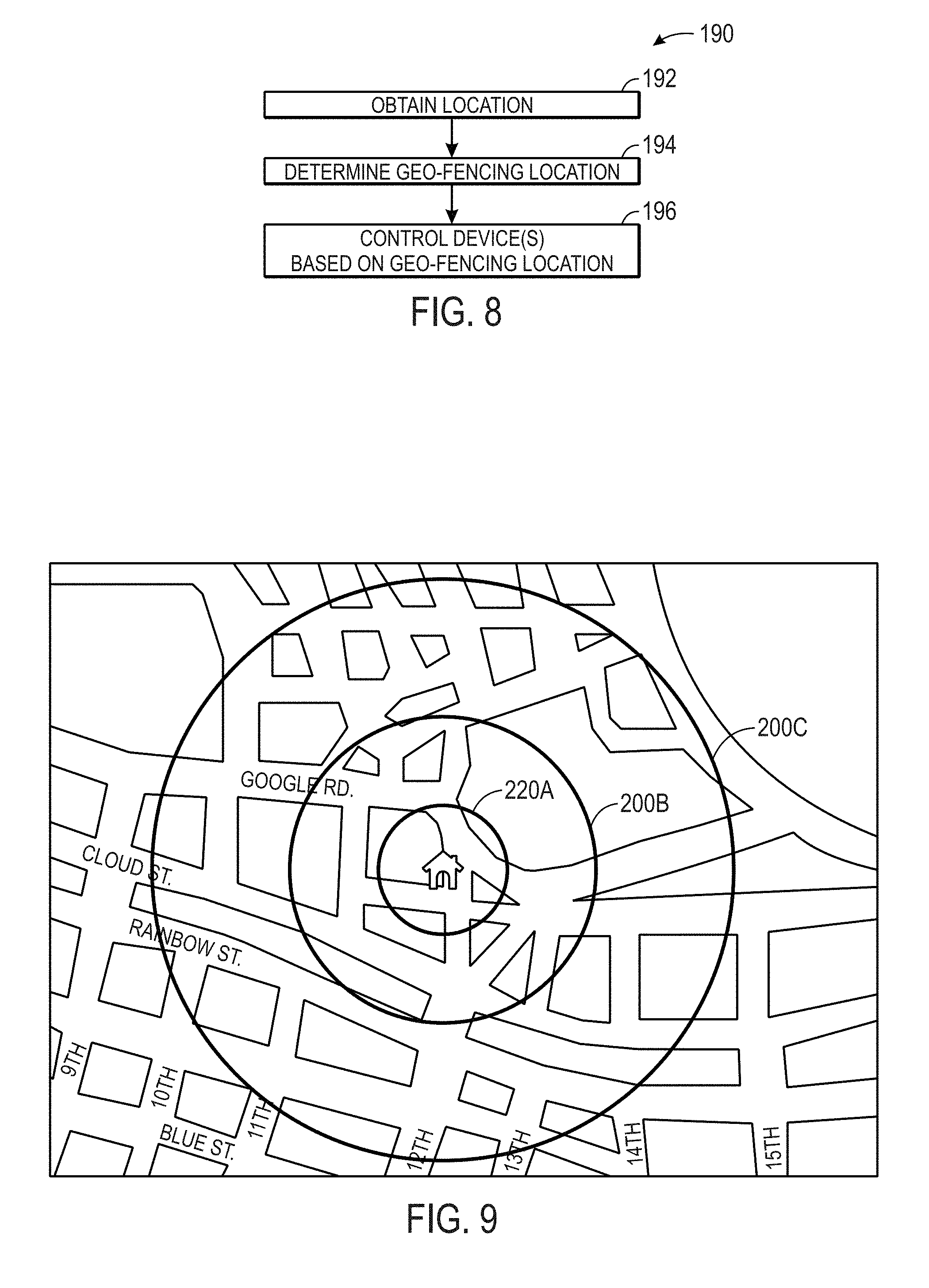
[0017] FIG. 8 is a flow diagram illustrating a method for controlling devices using geo-fencing, in accordance with an embodiment;
[0018] FIG. 9 is a block diagram illustrating a set of geo-fence boundaries, in accordance with an embodiment;
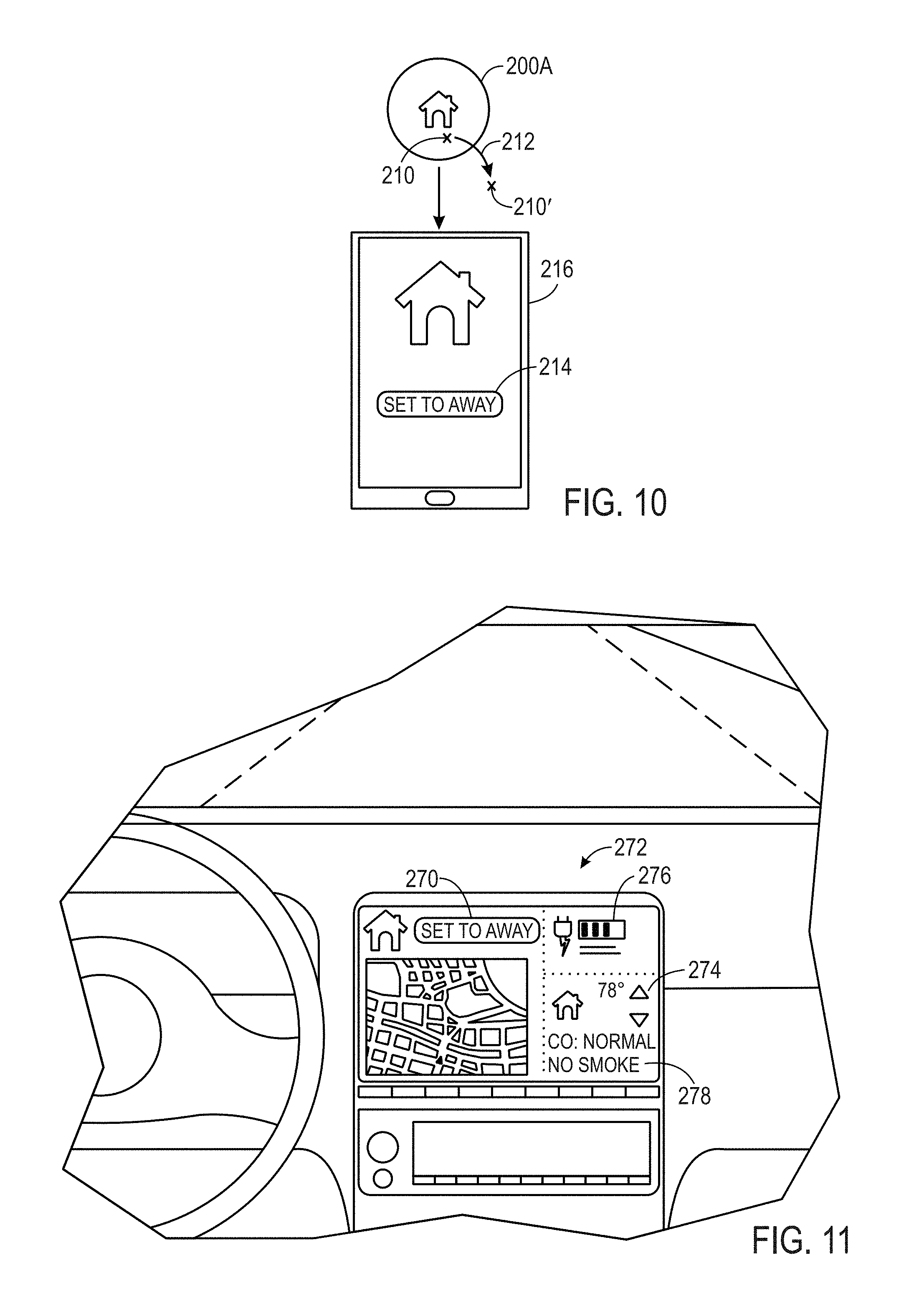
[0019] FIG. 10 is a block diagram illustrating a geo-fencing application on a handheld electronic device, in accordance with an embodiment;
[0020] FIG. 11 is a block diagram illustrating an application running from an in-dash interface, in accordance with an embodiment;
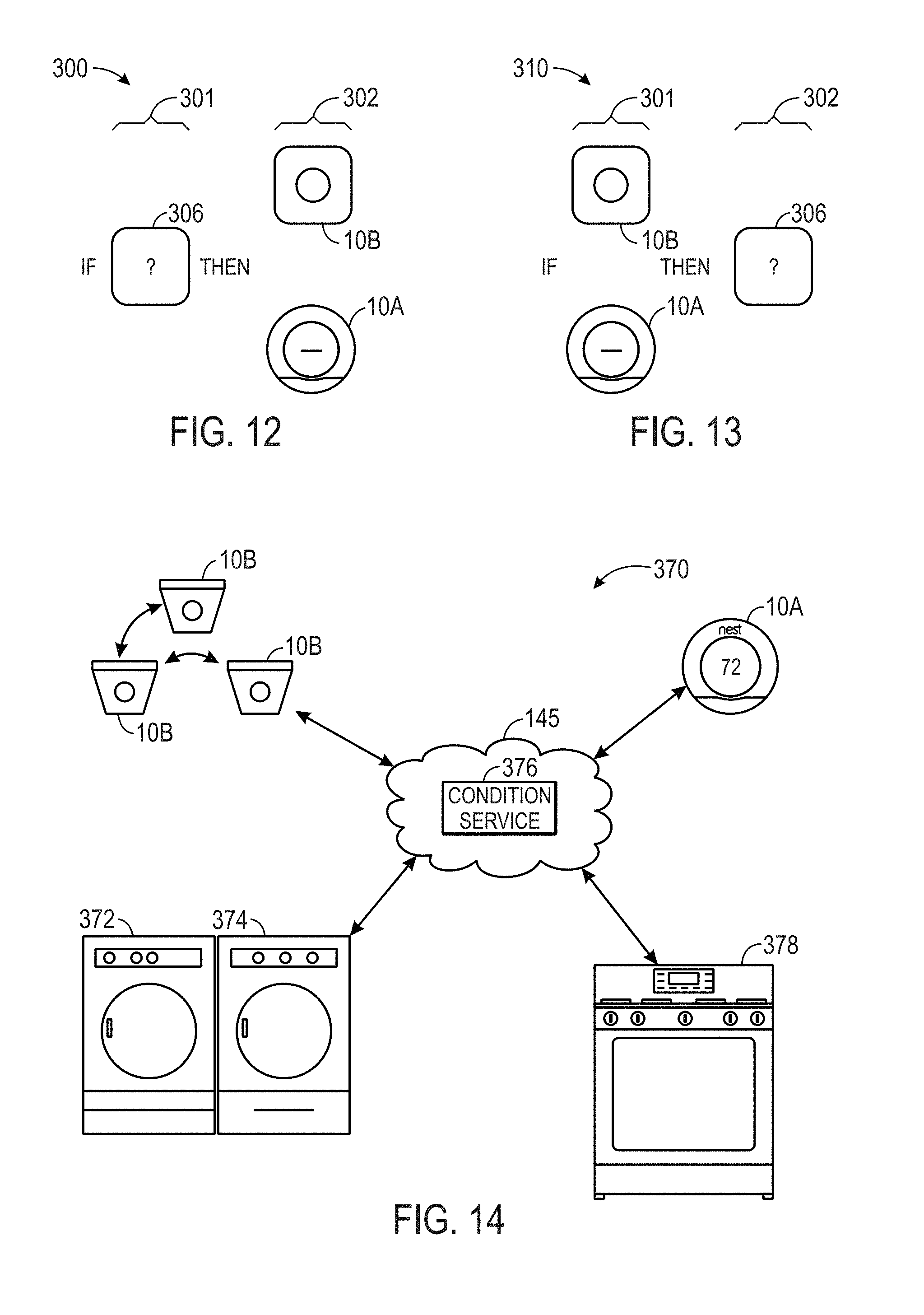
[0021] FIG. 12 is a schematic illustration of a conditional rule where a thermostat, a smoke/carbon monoxide detector, or both are outputs, in accordance with an embodiment;
[0022] FIG. 13 is a schematic illustration of a conditional rule where data from a thermostat, a smoke/carbon monoxide detector, or both are conditions, in accordance with an embodiment;
[0023] FIG. 14 is a block diagram of a system that integrates household appliances with a thermostat, smoke/carbon monoxide detector, or both, in accordance with an embodiment;
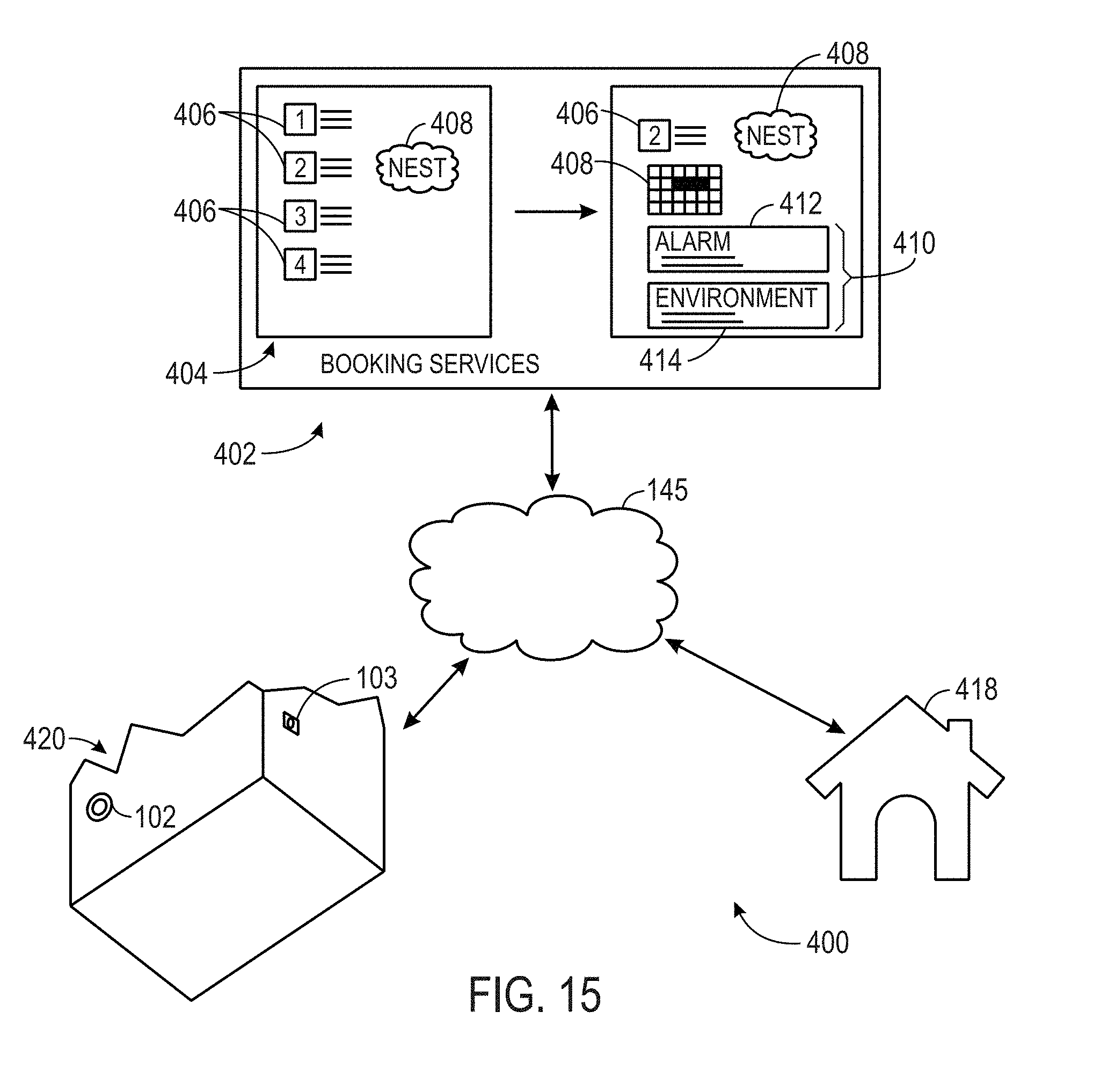
[0024] FIG. 15 is a block diagram of a system that integrates a booking service with a thermostat, smoke/carbon monoxide detector, an alarm system, or combination thereof, in accordance with an embodiment; and
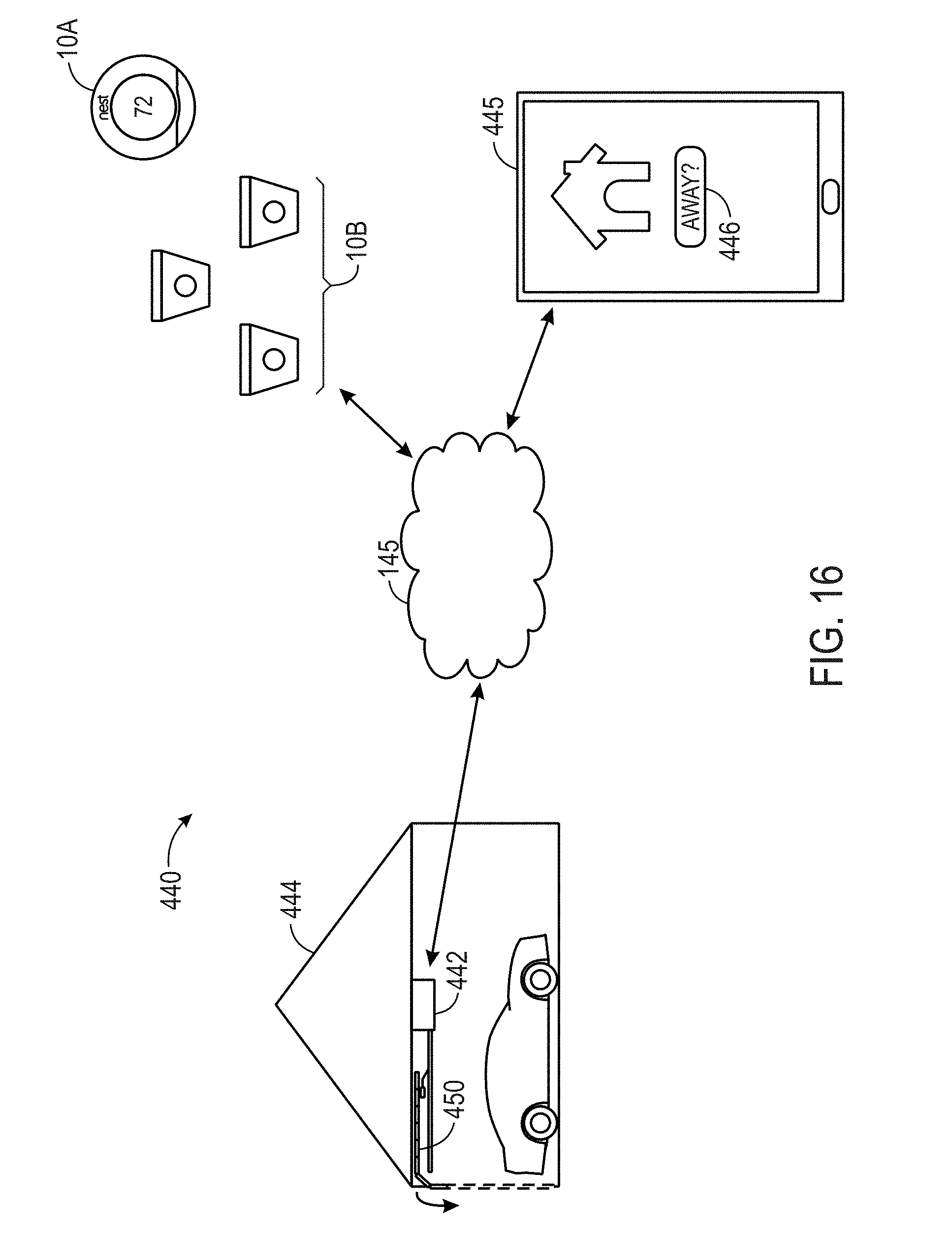
[0025] FIG. 16 is a block diagram of a system that integrates a garage door opener with a thermostat, smoke/carbon monoxide detector, or both, in accordance with an embodiment.
DETAILED DESCRIPTION OF SPECIFIC EMBODIMENTS
[0026] One or more specific embodiments will be described below. In an effort to provide a concise description of these embodiments, not all features of an actual implementation are described in the specification. It should be appreciated that in the development of any such actual implementation, as in any engineering or design project, numerous implementation-specific decisions must be made to achieve the developers' specific goals, such as compliance with system-related and business-related constraints, which may vary from one implementation to another. Moreover, it should be appreciated that such a development effort might be complex and time consuming, but would nevertheless be a routine undertaking of design, fabrication, and manufacture for those of ordinary skill having the benefit of this disclosure.
[0027] Embodiments of the present disclosure relate to an electronic device, such as a thermostat or a hazard detector (e.g., smoke detector), that may be disposed in a building (e.g., home or office) such that the electronic device may detect the presence of a human being in the building and distinguish between the presence of the human being and a pet. Generally, the electronic device may employ a sensor, such as a passive infrared (PIR) sensor, to detect the presence of a human being. However, each PIR sensor may be inherently sensitive to different levels of noise. By accounting for the different sensitivity levels of each PIR sensor, the electronic device may improve its detection of human being and better distinguish between the presence of human beings and pets.
[0028] Keeping this in mind, the electronic device may include a low-power processor that may store the sensor measurements acquired by the PIR sensor during a time period when the electronic device does not expect a human the building or portion of the building being monitored by electronic device is not expected to have a human being present. In one embodiment, after storing the sensor measurements over some period of time, the low-power processor may send the stored sensor measurements to a high-power processor of the electronic device. The high-power processor may then calculate a threshold or adjust the previous threshold for determining a presence of a human based on the stored sensor measurements that correspond to the time period when a human being is likely not present in the building. The high-power processor may then send the newly calculated or the adjusted threshold to the low-power processor. The low-power processor may then use the newly calculated or the adjusted threshold to detect the presence of a human. Since the new threshold is calculated based on the respective sensor measurements for the respective PIR sensor of a respective electronic device, the new threshold may compensate for the inherent sensitivity characteristics of the respective PIR sensor. As a result, the electronic device may detect the presence of a human being more effectively and efficiently.
[0029] Smart Device in Smart Home Environment
[0030] By way of introduction, FIG. 1 illustrates an example of a general device 10 that may that may be disposed within a building environment. In one embodiment, the device 10 may include one or more sensors 12, a user-interface component 14, a power supply 16 (e.g., including a power connection and/or battery), a network interface 18, a high-power processor 20, a low-power processor 22, a passive infrared (PIR) sensor 24, a light source 26, and the like.
[0031] The sensors 12, in certain embodiments, may detect various properties such as acceleration, temperature, humidity, water, supplied power, proximity, external motion, device motion, sound signals, ultrasound signals, light signals, fire, smoke, carbon monoxide, global-positioning-satellite (GPS) signals, radio-frequency (RF), other electromagnetic signals or fields, or the like. As such, the sensors 12 may include temperature sensor(s), humidity sensor(s), hazard-related sensor(s) or other environmental sensor(s), accelerometer(s), microphone(s), optical sensors up to and including camera(s) (e.g., charged coupled-device or video cameras), active or passive radiation sensors, GPS receiver(s) or radiofrequency identification detector(s). While FIG. 1 illustrates an embodiment with a single sensor, many embodiments may include multiple sensors. In some instances, the device 10 may include one or more primary sensors and one or more secondary sensors. Here, the primary sensor(s) may sense data central to the core operation of the device (e.g., sensing a temperature in a thermostat or sensing smoke in a smoke detector), while the secondary sensor(s) may sense other types of data (e.g., motion, light or sound), which can be used for energy-efficiency objectives or smart-operation obj ectives.
[0032] One or more user-interface components 14 in the device 10 may receive input from the user and/or present information to the user. The received input may be used to determine a setting. In certain embodiments, the user-interface components may include a mechanical or virtual component that responds to the user's motion. For example, the user can mechanically move a sliding component (e.g., along a vertical or horizontal track) or rotate a rotatable ring (e.g., along a circular track), or the user's motion along a touchpad may be detected. Such motions may correspond to a setting adjustment, which can be determined based on an absolute position of a user-interface component 14 or based on a displacement of a user-interface components 14 (e.g., adjusting a set point temperature by 1 degree F. for every 10.degree. rotation of a rotatable-ring component). Physically and virtually movable user-interface components can allow a user to set a setting along a portion of an apparent continuum. Thus, the user may not be confined to choose between two discrete options (e.g., as would be the case if up and down buttons were used) but can quickly and intuitively define a setting along a range of possible setting values. For example, a magnitude of a movement of a user-interface component may be associated with a magnitude of a setting adjustment, such that a user may dramatically alter a setting with a large movement or finely tune a setting with a small movement.
[0033] The user-interface components 14 may also include one or more buttons (e.g., up and down buttons), a keypad, a number pad, a switch, a microphone, and/or a camera (e.g., to detect gestures). In one embodiment, the user-interface component 14 may include a click-and-rotate annular ring component that may enable the user to interact with the component by rotating the ring (e.g., to adjust a setting) and/or by clicking the ring inwards (e.g., to select an adjusted setting or to select an option). In another embodiment, the user-interface component 14 may include a camera that may detect gestures (e.g., to indicate that a power or alarm state of a device is to be changed). In some instances, the device 10 may have one primary input component, which may be used to set a plurality of types of settings. The user-interface components 14 may also be configured to present information to a user via, e.g., a visual display (e.g., a thin-film-transistor display or organic light-emitting-diode display) and/or an audio speaker.
[0034] The power-supply component 16 may include a power connection and/or a local battery. For example, the power connection may connect the device 10 to a power source such as a line voltage source. In some instances, an AC power source can be used to repeatedly charge a (e.g., rechargeable) local battery, such that the battery may be used later to supply power to the device 10 when the AC power source is not available.
[0035] The network interface 18 may include a component that enables the device 10 to communicate between devices. As such, the network interface 18 may enable the device 10 to communicate with other devices 10 via a wired or wireless network. The network interface 18 may include a wireless card or some other transceiver connection to facilitate this communication.
[0036] The high-power processor 20 and the low-power processor 22 may support one or more of a variety of different device functionalities. As such, the high-power processor 20 and the low-power processor 22 may each include one or more processors configured and programmed to carry out and/or cause to be carried out one or more of the functionalities described herein. In one embodiment, the high-power processor 20 and the low-power processor 22 may include general-purpose processors carrying out computer code stored in local memory (e.g., flash memory, hard drive, random access memory), special-purpose processors or application-specific integrated circuits, combinations thereof, and/or using other types of hardware/firmware/software processing platforms. In certain embodiments, the high-power processor 20 may execute computationally intensive operations such as operating the user-interface component 14 and the like. The low-power processor 22, on the other hand, may manage less complex processes such as detecting a hazard or temperature from the sensor 12. In one embodiment, the low-power processor may wake or initialize the high-power processor for computationally intensive processes.
[0037] By way of example, the high-power processor 20 and the low-power processor 22 may detect when a location (e.g., a house or room) is occupied (i.e., includes a presence of a human), up to and including whether it is occupied by a specific person or is occupied by a specific number of people (e.g., relative to one or more thresholds). In one embodiment, this detection can occur, e.g., by analyzing microphone signals, detecting user movements (e.g., in front of a device), detecting openings and closings of doors or garage doors, detecting wireless signals, detecting an internet protocol (IP) address of a received signal, detecting operation of one or more devices within a time window, or the like. Moreover, the high-power processor 20 and the low-power processor 22 may include image recognition technology to identify particular occupants or objects.
[0038] In certain embodiments, the high-power processor 20 and the low-power processor 22 may detect the presence of a human using the PIR sensor 24. The PIR sensor 24 may be a passive infrared sensor that may measures infrared (IR) light radiating from objects in its field of view. As such, the PIR sensor 24 may detect the Infrared radiation emitted from an object.
[0039] In some instances, the high-power processor 20 may predict desirable settings and/or implement those settings. For example, based on the presence detection, the high-power processor 20 may adjust device settings to, e.g., conserve power when nobody is home or in a particular room or to accord with user preferences (e.g., general at-home preferences or user-specific preferences). As another example, based on the detection of a particular person, animal or object (e.g., a child, pet or lost object), the high-power processor 20 may initiate an audio or visual indicator of where the person, animal or object is or may initiate an alarm or security feature if an unrecognized person is detected under certain conditions (e.g., at night or when lights are off).
[0040] In some instances, devices may interact with each other such that events detected by a first device influences actions of a second device. For example, a first device can detect that a user has entered into a garage (e.g., by detecting motion in the garage, detecting a change in light in the garage or detecting opening of the garage door). The first device can transmit this information to a second device via the network interface 18, such that the second device can, e.g., adjust a home temperature setting, a light setting, a music setting, and/or a security-alarm setting. As another example, a first device can detect a user approaching a front door (e.g., by detecting motion or sudden light pattern changes). The first device may, e.g., cause a general audio or visual signal to be presented (e.g., such as sounding of a doorbell) or cause a location-specific audio or visual signal to be presented (e.g., to announce the visitor's presence within a room that a user is occupying).
[0041] In addition to detecting various types of events, the device 10 may include a light source 26 that may illuminate when a living being, such as a human, is detected as approaching. The light source 26 may include any type of light source such as one or more light-emitting diodes or the like. The light source 26 may be communicatively coupled to the high-power processor 20 and the low-power processor 22, which may provide a signal to cause the light source 26 to illuminate.
[0042] Keeping the foregoing in mind, FIG. 2 illustrates an example of a smart-home environment 30 within which one or more of the devices 10 of FIG. 1, methods, systems, services, and/or computer program products described further herein can be applicable. The depicted smart-home environment 30 includes a structure 32, which can include, e.g., a house, office building, garage, or mobile home. It will be appreciated that devices can also be integrated into a smart-home environment 30 that does not include an entire structure 32, such as an apartment, condominium, or office space. Further, the smart home environment can control and/or be coupled to devices outside of the actual structure 32. Indeed, several devices in the smart home environment need not physically be within the structure 32 at all. For example, a device controlling a pool heater or irrigation system can be located outside of the structure 32.
[0043] The depicted structure 32 includes a plurality of rooms 38, separated at least partly from each other via walls 40. The walls 40 can include interior walls or exterior walls. Each room can further include a floor 42 and a ceiling 44. Devices can be mounted on, integrated with and/or supported by a wall 40, floor 42 or ceiling 44.
[0044] In some embodiments, the smart-home environment 30 of FIG. 2 includes a plurality of devices 10, including intelligent, multi-sensing, network-connected devices, that can integrate seamlessly with each other and/or with a central server or a cloud-computing system to provide any of a variety of useful smart-home objectives. The smart-home environment 30 may include one or more intelligent, multi-sensing, network-connected thermostats 46 (hereinafter referred to as "smart thermostats 46"), one or more intelligent, network-connected, multi-sensing hazard detection units 50 (hereinafter referred to as "smart hazard detectors 50"), and one or more intelligent, multi-sensing, network-connected entryway interface devices 52 (hereinafter referred to as "smart doorbells 52"). According to embodiments, the smart thermostat 46 may include a Nest.RTM. Learning Thermostat--1st Generation T100577 or Nest.RTM. Learning Thermostat--2nd Generation T200577 by Nest Labs, Inc., among others. The smart thermostat 46 detects ambient climate characteristics (e.g., temperature and/or humidity) and controls a HVAC system 48 accordingly.
[0045] The smart hazard detector 50 may detect the presence of a hazardous substance or a substance indicative of a hazardous substance (e.g., smoke, fire, or carbon monoxide). The smart hazard detector 50 may include a Nest.RTM. Protect that may include sensors 12 such as smoke sensors, carbon monoxide sensors, and the like. As such, the hazard detector 50 may determine when smoke, fire, or carbon monoxide may be present within the building.
[0046] The smart doorbell 52 may detect a person's approach to or departure from a location (e.g., an outer door), control doorbell functionality, announce a person's approach or departure via audio or visual means, or control settings on a security system (e.g., to activate or deactivate the security system when occupants go and come). The smart doorbell 52 may interact with other devices 10 based on whether someone has approached or entered the smart-home environment 30.
[0047] In some embodiments, the smart-home environment 30 further includes one or more intelligent, multi-sensing, network-connected wall switches 54 (hereinafter referred to as "smart wall switches 54"), along with one or more intelligent, multi-sensing, network-connected wall plug interfaces 56 (hereinafter referred to as "smart wall plugs 56"). The smart wall switches 54 may detect ambient lighting conditions, detect room-occupancy states, and control a power and/or dim state of one or more lights. In some instances, smart wall switches 54 may also control a power state or speed of a fan, such as a ceiling fan. The smart wall plugs 56 may detect occupancy of a room or enclosure and control supply of power to one or more wall plugs (e.g., such that power is not supplied to the plug if nobody is at home).
[0048] Still further, in some embodiments, the device 10 within the smart-home environment 30 may further includes a plurality of intelligent, multi-sensing, network-connected appliances 58 (hereinafter referred to as "smart appliances 58"), such as refrigerators, stoves and/or ovens, televisions, washers, dryers, lights, stereos, intercom systems, garage-door openers, floor fans, ceiling fans, wall air conditioners, pool heaters, irrigation systems, security systems, and so forth. According to embodiments, the network-connected appliances 58 are made compatible with the smart-home environment by cooperating with the respective manufacturers of the appliances. For example, the appliances can be space heaters, window AC units, motorized duct vents, etc. When plugged in, an appliance can announce itself to the smart-home network, such as by indicating what type of appliance it is, and it can automatically integrate with the controls of the smart-home. Such communication by the appliance to the smart home can be facilitated by any wired or wireless communication protocols known by those having ordinary skill in the art. The smart home also can include a variety of non-communicating legacy appliances 68, such as old conventional washer/dryers, refrigerators, and the like which can be controlled, albeit coarsely (ON/OFF), by virtue of the smart wall plugs 56. The smart-home environment 30 can further include a variety of partially communicating legacy appliances 70, such as infrared ("IR") controlled wall air conditioners or other IR-controlled devices, which can be controlled by IR signals provided by the smart hazard detectors 50 or the smart wall switches 54.
[0049] According to embodiments, the smart thermostats 46, the smart hazard detectors 50, the smart doorbells 52, the smart wall switches 54, the smart wall plugs 56, and other devices of the smart-home environment 30 are modular and can be incorporated into older and new houses. For example, the devices 10 are designed around a modular platform consisting of two basic components: a head unit and a back plate, which is also referred to as a docking station. Multiple configurations of the docking station are provided so as to be compatible with any home, such as older and newer homes. However, all of the docking stations include a standard head-connection arrangement, such that any head unit can be removably attached to any docking station. Thus, in some embodiments, the docking stations are interfaces that serve as physical connections to the structure and the voltage wiring of the homes, and the interchangeable head units contain all of the sensors 12, processors 28, user interfaces 14, the power supply 16, the network interface 18, and other functional components of the devices described above.
[0050] Many different commercial and functional possibilities for provisioning, maintenance, and upgrade are possible. For example, after years of using any particular head unit, a user will be able to buy a new version of the head unit and simply plug it into the old docking station. There are also many different versions for the head units, such as low-cost versions with few features, and then a progression of increasingly-capable versions, up to and including extremely fancy head units with a large number of features. Thus, it should be appreciated that the various versions of the head units can all be interchangeable, with any of them working when placed into any docking station. This can advantageously encourage sharing and re-deployment of old head units--for example, when an important high-capability head unit, such as a hazard detector, is replaced by a new version of the head unit, then the old head unit can be re-deployed to a back room or basement, etc. According to embodiments, when first plugged into a docking station, the head unit can ask the user (by 2D LCD display, 2D/3D holographic projection, voice interaction, etc.) a few simple questions such as, "Where am I" and the user can indicate "living room", "kitchen" and so forth.
[0051] The smart-home environment 30 may also include communication with devices outside of the physical home but within a proximate geographical range of the home. For example, the smart-home environment 30 may include a pool heater monitor 34 that communicates a current pool temperature to other devices within the smart-home environment 30 or receives commands for controlling the pool temperature. Similarly, the smart-home environment 30 may include an irrigation monitor 36 that communicates information regarding irrigation systems within the smart-home environment 30 and/or receives control information for controlling such irrigation systems. According to embodiments, an algorithm is provided for considering the geographic location of the smart-home environment 30, such as based on the zip code or geographic coordinates of the home. The geographic information is then used to obtain data helpful for determining optimal times for watering, such data may include sun location information, temperature, dewpoint, soil type of the land on which the home is located, etc.
[0052] By virtue of network connectivity, one or more of the smart-home devices of FIG. 2 can further allow a user to interact with the device even if the user is not proximate to the device. For example, a user can communicate with a device using a computer (e.g., a desktop computer, laptop computer, or tablet) or other portable electronic device (e.g., a smartphone) 66. A web page or app can be configured to receive communications from the user and control the device based on the communications and/or to present information about the device's operation to the user. For example, the user can view a current setpoint temperature for a device and adjust it using a computer. The user can be in the structure during this remote communication or outside the structure.
[0053] As discussed, users can control the smart thermostat and other smart devices in the smart-home environment 30 using a network-connected computer or portable electronic device 66. In some examples, some or all of the occupants (e.g., individuals who live in the home) can register their device 66 with the smart-home environment 30. Such registration can be made at a central server to authenticate the occupant and/or the device as being associated with the home and to give permission to the occupant to use the device to control the smart devices in the home. An occupant can use their registered device 66 to remotely control the smart devices of the home, such as when the occupant is at work or on vacation. The occupant may also use their registered device to control the smart devices when the occupant is actually located inside the home, such as when the occupant is sitting on a couch inside the home. It should be appreciated that instead of or in addition to registering devices 66, the smart-home environment 30 makes inferences about which individuals live in the home and are therefore occupants and which devices 66 are associated with those individuals. As such, the smart-home environment "learns" who is an occupant and permits the devices 66 associated with those individuals to control the smart devices of the home.
[0054] In some instances, guests desire to control the smart devices. For example, the smart-home environment may receive communication from an unregistered mobile device of an individual inside of the home, where said individual is not recognized as an occupant of the home. Further, for example, a smart-home environment may receive communication from a mobile device of an individual who is known to be or who is registered as a guest.
[0055] According to embodiments, a guest-layer of controls can be provided to guests of the smart-home environment 30. The guest-layer of controls gives guests access to basic controls (e.g., a judicially selected subset of features of the smart devices), such as temperature adjustments, but it locks out other functionalities. The guest layer of controls can be thought of as a "safe sandbox" in which guests have limited controls, but they do not have access to more advanced controls that could fundamentally alter, undermine, damage, or otherwise impair the occupant-desired operation of the smart devices. For example, the guest layer of controls will not permit the guest to adjust the heat-pump lockout temperature.
[0056] A use case example of this is when a guest is in a smart home, the guest could walk up to the thermostat and turn the dial manually, but the guest may not want to walk around the house "hunting" the thermostat, especially at night while the home is dark and others are sleeping. Further, the guest may not want to go through the hassle of downloading the necessary application to their device for remotely controlling the thermostat. In fact, the guest may not have the home owner's login credentials, etc., and therefore cannot remotely control the thermostat via such an application. Accordingly, according to embodiments of the invention, the guest can open a mobile browser on their mobile device, type a keyword, such as "NEST" into the URL field and tap "Go" or "Search", etc. In response, the device presents the guest with a user interface which allows the guest to move the target temperature between a limited range, such as 65 and 80 degrees Fahrenheit. As discussed, the user interface provides a guest layer of controls that are limited to basic functions. The guest cannot change the target humidity, modes, or view energy history.
[0057] According to embodiments, to enable guests to access the user interface that provides the guest layer of controls, a local webserver is provided that is accessible in the local area network (LAN). It does not require a password, because physical presence inside the home is established reliably enough by the guest's presence on the LAN. In some embodiments, during installation of the smart device, such as the smart thermostat, the home owner is asked if they want to enable a Local Web App (LWA) on the smart device. Business owners will likely say no; home owners will likely say yes. When the LWA option is selected, the smart device broadcasts to the LAN that the above referenced keyword, such as "NEST", is now a host alias for its local web server. Thus, no matter whose home a guest goes to, that same keyword (e.g., "NEST") is always the URL you use to access the LWA, provided the smart device is purchased from the same manufacturer. Further, according to embodiments, if there is more than one smart device on the LAN, the second and subsequent smart devices do not offer to set up another LWA. Instead, they register themselves as target candidates with the master LWA. And in this case the LWA user would be asked which smart device they want to change the temperature on before getting the simplified user interface for the particular smart device they choose.
[0058] According to embodiments, a guest layer of controls may also be provided to users by means other than a device 66. For example, the smart device, such as the smart thermostat, may be equipped with walkup-identification technology (e.g., face recognition, RFID, ultrasonic sensors) that "fingerprints" or creates a "signature" for the occupants of the home. The walkup-identification technology can be the same as or similar to the fingerprinting and signature creating techniques described in other sections of this application. In operation, when a person who does not live in the home or is otherwise not registered with the smart home or whose fingerprint or signature is not recognized by the smart home "walks up" to a smart device, the smart device provides the guest with the guest layer of controls, rather than full controls.
[0059] As described below, the smart thermostat 46 and other smart devices "learn" by observing occupant behavior. For example, the smart thermostat learns occupants' preferred temperature set-points for mornings and evenings, and it learns when the occupants are asleep or awake, as well as when the occupants are typically away or at home, for example. According to embodiments, when a guest controls the smart devices, such as the smart thermostat, the smart devices do not "learn" from the guest. This prevents the guest's adjustments and controls from affecting the learned preferences of the occupants.
[0060] According to some embodiments, a smart television remote control is provided. The smart remote control recognizes occupants by thumbprint, visual identification, RFID, etc., and it recognizes a user as a guest or as someone belonging to a particular class having limited control and access (e.g., child). Upon recognizing the user as a guest or someone belonging to a limited class, the smart remote control only permits that user to view a subset of channels and to make limited adjustments to the settings of the television and other devices. For example, a guest cannot adjust the digital video recorder (DVR) settings, and a child is limited to viewing child-appropriate programming.
[0061] According to some embodiments, similar controls are provided for other instruments, utilities, and devices in the house. For example, sinks, bathtubs, and showers can be controlled by smart spigots that recognize users as guests or as children and therefore prevent water from exceeding a designated temperature that is considered safe.
[0062] In some embodiments, in addition to containing processing and sensing capabilities, each of the devices 34, 36, 46, 50, 52, 54, 56, and 58 (collectively referred to as "the smart devices") is capable of data communications and information sharing with any other of the smart devices, as well as to any central server or cloud-computing system or any other device that is network-connected anywhere in the world. The required data communications can be carried out using any of a variety of custom or standard wireless protocols (Wi-Fi, ZigBee, 6LoWPAN, etc.) and/or any of a variety of custom or standard wired protocols (CAT6 Ethernet, HomePlug, etc.).
[0063] According to embodiments, all or some of the smart devices can serve as wireless or wired repeaters. For example, a first one of the smart devices can communicate with a second one of the smart device via a wireless router 60. The smart devices can further communicate with each other via a connection to a network, such as the Internet 62. Through the Internet 62, the smart devices can communicate with a central server or a cloud-computing system 64. The central server or cloud-computing system 64 can be associated with a manufacturer, support entity, or service provider associated with the device. For one embodiment, a user may be able to contact customer support using a device itself rather than needing to use other communication means such as a telephone or Internet-connected computer. Further, software updates can be automatically sent from the central server or cloud-computing system 64 to devices (e.g., when available, when purchased, or at routine intervals).
[0064] According to embodiments, the smart devices combine to create a mesh network of spokesman and low-power nodes in the smart-home environment 30, where some of the smart devices are "spokesman" nodes and others are "low-powered" nodes. Some of the smart devices in the smart-home environment 30 are battery powered, while others have a regular and reliable power source, such as by connecting to wiring (e.g., to 120V line voltage wires) behind the walls 40 of the smart-home environment. The smart devices that have a regular and reliable power source are referred to as "spokesman" nodes. These nodes are equipped with the capability of using any wireless protocol or manner to facilitate bidirectional communication with any of a variety of other devices in the smart-home environment 30 as well as with the central server or cloud-computing system 64. On the other hand, the devices that are battery powered are referred to as "low-power" nodes. These nodes tend to be smaller than spokesman nodes and can only communicate using wireless protocols that requires very little power, such as Zigbee, 6LoWPAN, etc. Further, some, but not all, low-power nodes are incapable of bidirectional communication. These low-power nodes send messages, but they are unable to "listen". Thus, other devices in the smart-home environment 30, such as the spokesman nodes, cannot send information to these low-power nodes.
[0065] As described, the smart devices serve as low-power and spokesman nodes to create a mesh network in the smart-home environment 30. Individual low-power nodes in the smart-home environment regularly send out messages regarding what they are sensing, and the other low-powered nodes in the smart-home environment--in addition to sending out their own messages--repeat the messages, thereby causing the messages to travel from node to node (i.e., device to device) throughout the smart-home environment 30. The spokesman nodes in the smart-home environment 30 are able to "drop down" to low-powered communication protocols to receive these messages, translate the messages to other communication protocols, and send the translated messages to other spokesman nodes and/or the central server or cloud-computing system 64. Thus, the low-powered nodes using low-power communication protocols are able send messages across the entire smart-home environment 30 as well as over the Internet 62 to the central server or cloud-computing system 64. According to embodiments, the mesh network enables the central server or cloud-computing system 64 to regularly receive data from all of the smart devices in the home, make inferences based on the data, and send commands back to one of the smart devices to accomplish some of the smart-home objectives described herein.
[0066] As described, the spokesman nodes and some of the low-powered nodes are capable of "listening". Accordingly, users, other devices, and the central server or cloud-computing system 64 can communicate controls to the low-powered nodes. For example, a user can use the portable electronic device (e.g., a smartphone) 66 to send commands over the Internet 62 to the central server or cloud-computing system 64, which then relays the commands to the spokesman nodes in the smart-home environment 30. The spokesman nodes drop down to a low-power protocol to communicate the commands to the low-power nodes throughout the smart-home environment, as well as to other spokesman nodes that did not receive the commands directly from the central server or cloud-computing system 64.
[0067] An example of a low-power node is a smart night light 65. In addition to housing a light source, the smart night light 65 houses an occupancy sensor, such as an ultrasonic or passive IR sensor, and an ambient light sensor, such as a photoresistor or a single-pixel sensor that measures light in the room. In some embodiments, the smart night light 65 is configured to activate the light source when its ambient light sensor detects that the room is dark and when its occupancy sensor detects that someone is in the room. In other embodiments, the smart night light 65 is simply configured to activate the light source when its ambient light sensor detects that the room is dark. Further, according to embodiments, the smart night light 65 includes a low-power wireless communication chip (e.g., ZigBee chip) that regularly sends out messages regarding the occupancy of the room and the amount of light in the room, including instantaneous messages coincident with the occupancy sensor detecting the presence of a person in the room. As mentioned above, these messages may be sent wirelessly, using the mesh network, from node to node (i.e., smart device to smart device) within the smart-home environment 30 as well as over the Internet 62 to the central server or cloud-computing system 64.
[0068] Other examples of low-powered nodes include battery-operated versions of the smart hazard detectors 50. These smart hazard detectors 50 are often located in an area without access to constant and reliable power and, as discussed in detail below, may include any number and type of sensors, such as smoke/fire/heat sensors, carbon monoxide/dioxide sensors, occupancy/motion sensors, ambient light sensors, temperature sensors, humidity sensors, and the like. Furthermore, smart hazard detectors 50 can send messages that correspond to each of the respective sensors to the other devices and the central server or cloud-computing system 64, such as by using the mesh network as described above.
[0069] Examples of spokesman nodes include smart thermostats 46, smart doorbells 52, smart wall switches 54, and smart wall plugs 56. These devices 46, 52, 54, and 56 are often located near and connected to a reliable power source, and therefore can include more power-consuming components, such as one or more communication chips capable of bidirectional communication in any variety of protocols.
[0070] In some embodiments, these low-powered and spokesman nodes (e.g., devices 46, 50, 52, 54, 56, 58, and 65) can function as "tripwires" for an alarm system in the smart-home environment. For example, in the event a perpetrator circumvents detection by alarm sensors located at windows, doors, and other entry points of the smart-home environment 30, the alarm could be triggered upon receiving an occupancy, motion, heat, sound, etc. message from one or more of the low-powered and spokesman nodes in the mesh network. For example, upon receiving a message from a smart night light 65 indicating the presence of a person, the central server or cloud-computing system 64 or some other device could trigger an alarm, provided the alarm is armed at the time of detection. Thus, the alarm system could be enhanced by various low-powered and spokesman nodes located throughout the smart-home environment 30. In this example, a user could enhance the security of the smart-home environment 30 by buying and installing extra smart nightlights 65. However, in a scenario where the perpetrator uses a radio transceiver to jam the wireless network, the devices 10 may be incapable of communicating with each other. Therefore, as discussed in detail below, the present techniques provide network communication jamming attack detection and notification solutions to such a problem.
[0071] In some embodiments, the mesh network can be used to automatically turn on and off lights as a person transitions from room to room. For example, the low-powered and spokesman nodes detect the person's movement through the smart-home environment and communicate corresponding messages through the mesh network. Using the messages that indicate which rooms are occupied, the central server or cloud-computing system 64 or some other device activates and deactivates the smart wall switches 54 to automatically provide light as the person moves from room to room in the smart-home environment 30. Further, users may provide pre-configuration information that indicates which smart wall plugs 56 provide power to lamps and other light sources, such as the smart night light 65. Alternatively, this mapping of light sources to wall plugs 56 can be done automatically (e.g., the smart wall plugs 56 detect when a light source is plugged into it, and it sends a corresponding message to the central server or cloud-computing system 64). Using this mapping information in combination with messages that indicate which rooms are occupied, the central server or cloud-computing system 64 or some other device activates and deactivates the smart wall plugs 56 that provide power to lamps and other light sources so as to track the person's movement and provide light as the person moves from room to room.
[0072] In some embodiments, the mesh network of low-powered and spokesman nodes can be used to provide exit lighting in the event of an emergency. In some instances, to facilitate this, users provide pre-configuration information that indicates exit routes in the smart-home environment 30. For example, for each room in the house, the user provides a map of the best exit route. It should be appreciated that instead of a user providing this information, the central server or cloud-computing system 64 or some other device could automatically determine the routes using uploaded maps, diagrams, architectural drawings of the smart-home house, as well as using a map generated based on positional information obtained from the nodes of the mesh network (e.g., positional information from the devices is used to construct a map of the house). In operation, when an alarm is activated (e.g., when one or more of the smart hazard detector 50 detects smoke and activates an alarm), the central server or cloud-computing system 64 or some other device uses occupancy information obtained from the low-powered and spokesman nodes to determine which rooms are occupied and then turns on lights (e.g., nightlights 65, wall switches 54, wall plugs 56 that power lamps, etc.) along the exit routes from the occupied rooms so as to provide emergency exit lighting.
[0073] Further included and illustrated in the smart-home environment 30 of FIG. 2 are service robots 69 each configured to carry out, in an autonomous manner, any of a variety of household tasks. For some embodiments, the service robots 69 can be respectively configured to perform floor sweeping, floor washing, etc. in a manner similar to that of known commercially available devices such as the ROOMBA.TM. and SCOOBA.TM. products sold by iRobot, Inc. of Bedford, Mass. Tasks such as floor sweeping and floor washing can be considered as "away" or "while-away" tasks for purposes of the instant description, as it is generally more desirable for these tasks to be performed when the occupants are not present. For other embodiments, one or more of the service robots 69 are configured to perform tasks such as playing music for an occupant, serving as a localized thermostat for an occupant, serving as a localized air monitor/purifier for an occupant, serving as a localized baby monitor, serving as a localized hazard detector for an occupant, and so forth, it being generally more desirable for such tasks to be carried out in the immediate presence of the human occupant. For purposes of the instant description, such tasks can be considered as "human-facing" or "human-centric" tasks.
[0074] When serving as a localized thermostat for an occupant, a particular one of the service robots 69 can be considered to be facilitating what can be called a "personal comfort-area network" for the occupant, with the objective being to keep the occupant's immediate space at a comfortable temperature wherever that occupant may be located in the home. This can be contrasted with conventional wall-mounted room thermostats, which have the more attenuated objective of keeping a statically-defined structural space at a comfortable temperature. According to one embodiment, the localized-thermostat service robot 69 is configured to move itself into the immediate presence (e.g., within five feet) of a particular occupant who has settled into a particular location in the home (e.g. in the dining room to eat their breakfast and read the news). The localized-thermostat service robot 69 includes a temperature sensor, a processor, and wireless communication components configured such that control communications with the HVAC system, either directly or through a wall-mounted wirelessly communicating thermostat coupled to the HVAC system, are maintained and such that the temperature in the immediate vicinity of the occupant is maintained at their desired level. If the occupant then moves and settles into another location (e.g. to the living room couch to watch television), the localized-thermostat service robot 69 proceeds to move and park itself next to the couch and keep that particular immediate space at a comfortable temperature.
[0075] Technologies by which the localized-thermostat service robot 69 (and/or the larger smart-home system of FIG. 2) can identify and locate the occupant whose personal-area space is to be kept at a comfortable temperature can include, but are not limited to, RFID sensing (e.g., person having an RFID bracelet, RFID necklace, or RFID key fob), synthetic vision techniques (e.g., video cameras and face recognition processors), audio techniques (e.g., voice, sound pattern, vibration pattern recognition), ultrasound sensing/imaging techniques, and infrared or near-field communication (NFC) techniques (e.g., person wearing an infrared or NFC-capable smartphone), along with rules-based inference engines or artificial intelligence techniques that draw useful conclusions from the sensed information (e.g., if there is only a single occupant present in the home, then that is the person whose immediate space should be kept at a comfortable temperature, and the selection of the desired comfortable temperature should correspond to that occupant's particular stored profile).
[0076] When serving as a localized air monitor/purifier for an occupant, a particular service robot 69 can be considered to be facilitating what can be called a "personal health-area network" for the occupant, with the objective being to keep the air quality in the occupant's immediate space at healthy levels. Alternatively or in conjunction therewith, other health-related functions can be provided, such as monitoring the temperature or heart rate of the occupant (e.g., using finely remote sensors, near-field communication with on-person monitors, etc.). When serving as a localized hazard detector for an occupant, a particular service robot 69 can be considered to be facilitating what can be called a "personal safety-area network" for the occupant, with the objective being to ensure there is no excessive carbon monoxide, smoke, fire, etc., in the immediate space of the occupant. Methods analogous to those described above for personal comfort-area networks in terms of occupant identifying and tracking are likewise applicable for personal health-area network and personal safety-area network embodiments.
[0077] According to some embodiments, the above-referenced facilitation of personal comfort-area networks, personal health-area networks, personal safety-area networks, and/or other such human-facing functionalities of the service robots 69, are further enhanced by logical integration with other smart sensors in the home according to rules-based inferencing techniques or artificial intelligence techniques for achieving better performance of those human-facing functionalities and/or for achieving those goals in energy-conserving or other resource-conserving ways. Thus, for one embodiment relating to personal health-area networks, the air monitor/purifier service robot 69 can be configured to detect whether a household pet is moving toward the currently settled location of the occupant (e.g., using on-board sensors and/or by data communications with other smart-home sensors along with rules-based inferencing/artificial intelligence techniques), and if so, the air purifying rate is immediately increased in preparation for the arrival of more airborne pet dander. For another embodiment relating to personal safety-area networks, the hazard detector service robot 69 can be advised by other smart-home sensors that the temperature and humidity levels are rising in the kitchen, which is nearby to the occupant's current dining room location, and responsive to this advisory the hazard detector service robot 69 will temporarily raise a hazard detection threshold, such as a smoke detection threshold, under an inference that any small increases in ambient smoke levels will most likely be due to cooking activity and not due to a genuinely hazardous condition.
[0078] The above-described "human-facing" and "away" functionalities can be provided, without limitation, by multiple distinct service robots 69 having respective dedicated ones of such functionalities, by a single service robot 69 having an integration of two or more different ones of such functionalities, and/or any combinations thereof (including the ability for a single service robot 69 to have both "away" and "human facing" functionalities) without departing from the scope of the present teachings. Electrical power can be provided by virtue of rechargeable batteries or other rechargeable methods, such as an out-of-the-way docking station to which the service robots 69 will automatically dock and recharge its batteries (if needed) during periods of inactivity. Preferably, each service robot 69 includes wireless communication components that facilitate data communications with one or more of the other wirelessly communicating smart-home sensors of FIG. 2 and/or with one or more other service robots 69 (e.g., using Wi-Fi, Zigbee, Z-Wave, 6LoWPAN, etc.), and one or more of the smart-home devices 10 can be in communication with a remote server over the Internet. Alternatively or in conjunction therewith, each service robot 69 can be configured to communicate directly with a remote server by virtue of cellular telephone communications, satellite communications, 3G/4G network data communications, or other direct communication method.
[0079] Provided according to some embodiments are systems and methods relating to the integration of the service robot(s) 69 with home security sensors and related functionalities of the smart home system. The embodiments are particularly applicable and advantageous when applied for those service robots 69 that perform "away" functionalities or that otherwise are desirable to be active when the home is unoccupied (hereinafter "away-service robots"). Included in the embodiments are methods and systems for ensuring that home security systems, intrusion detection systems, and/or occupancy-sensitive environmental control systems (for example, occupancy-sensitive automated setback thermostats that enter into a lower-energy-using condition when the home is unoccupied) are not erroneously triggered by the away-service robots.
[0080] Provided according to one embodiment is a home automation and security system (e.g., as shown in FIG. 2) that is remotely monitored by a monitoring service by virtue of automated systems (e.g., cloud-based servers or other central servers, hereinafter "central server") that are in data communications with one or more network-connected elements of the home automation and security system. The away-service robots are configured to be in operative data communication with the central server, and are configured such that they remain in a non-away-service state (e.g., a dormant state at their docking station) unless permission is granted from the central server (e.g., by virtue of an "away-service-OK" message from the central server) to commence their away-service activities. An away-state determination made by the system, which can be arrived at (i) exclusively by local on-premises smart device(s) based on occupancy sensor data, (ii) exclusively by the central server based on received occupancy sensor data and/or based on received proximity-related information such as GPS coordinates from user smartphones or automobiles, or (iii) any combination of (i) and (ii) can then trigger the granting of away-service permission to the away-service robots by the central server. During the course of the away-service robot activity, during which the away-service robots may continuously detect and send their in-home location coordinates to the central server, the central server can readily filter signals from the occupancy sensing devices to distinguish between the away-service robot activity versus any unexpected intrusion activity, thereby avoiding a false intrusion alarm condition while also ensuring that the home is secure. Alternatively or in conjunction therewith, the central server may provide filtering data (such as an expected occupancy-sensing profile triggered by the away-service robots) to the occupancy sensing nodes or associated processing nodes of the smart home, such that the filtering is performed at the local level. Although somewhat less secure, it would also be within the scope of the present teachings for the central server to temporarily disable the occupancy sensing equipment for the duration of the away-service robot activity.
[0081] According to another embodiment, functionality similar to that of the central server in the above example can be performed by an on-site computing device such as a dedicated server computer, a "master" home automation console or panel, or as an adjunct function of one or more of the smart-home devices of FIG. 2. In such an embodiment, there would be no dependency on a remote service provider to provide the "away-service-OK" permission to the away-service robots and the false-alarm-avoidance filtering service or filter information for the sensed intrusion detection signals.
[0082] According to other embodiments, there are provided methods and systems for implementing away-service robot functionality while avoiding false home security alarms and false occupancy-sensitive environmental controls without the requirement of a single overall event orchestrator. For purposes of the simplicity in the present disclosure, the home security systems and/or occupancy-sensitive environmental controls that would be triggered by the motion, noise, vibrations, or other disturbances of the away-service robot activity are referenced simply as "activity sensing systems," and when so triggered will yield a "disturbance-detected" outcome representative of the false trigger (for example, an alarm message to a security service, or an "arrival" determination for an automated setback thermostat that causes the home to be heated or cooled to a more comfortable "occupied" setpoint temperature). According to one embodiment, the away-service robots are configured to emit a standard ultrasonic sound throughout the course of their away-service activity, the activity sensing systems are configured to detect that standard ultrasonic sound, and the activity sensing systems are further configured such that no disturbance-detected outcome will occur for as long as that standard ultrasonic sound is detected. For other embodiments, the away-service robots are configured to emit a standard notification signal throughout the course of their away-service activity, the activity sensing systems are configured to detect that standard notification signal, and the activity sensing systems are further configured such that no disturbance-detected outcome will occur for as long as that standard notification signal is detected, wherein the standard notification signal comprises one or more of: an optical notifying signal; an audible notifying signal; an infrared notifying signal; an infrasonic notifying signal; a wirelessly transmitted data notification signal (e.g., an IP broadcast, multicast, or unicast notification signal, or a notification message sent in an TCP/IP two-way communication session).
[0083] According to some embodiments, the notification signals sent by the away-service robots to the activity sensing systems are authenticated and encrypted such that the notifications cannot be learned and replicated by a potential burglar. Any of a variety of known encryption/authentication schemes can be used to ensure such data security including, but not limited to, methods involving third party data security services or certificate authorities. For some embodiments, a permission request-response model can be used, wherein any particular away-service robot requests permission from each activity sensing system in the home when it is ready to perform its away-service tasks, and does not initiate such activity until receiving a "yes" or "permission granted" message from each activity sensing system (or from a single activity sensing system serving as a "spokesman" for all of the activity sensing systems). One advantage of the described embodiments that do not require a central event orchestrator is that there can (optionally) be more of an arms-length relationship between the supplier(s) of the home security/environmental control equipment, on the one hand, and the supplier(s) of the away-service robot(s), on the other hand, as it is only required that there is the described standard one-way notification protocol or the described standard two-way request/permission protocol to be agreed upon by the respective suppliers.
[0084] According to still other embodiments, the activity sensing systems are configured to detect sounds, vibrations, RF emissions, or other detectable environmental signals or "signatures" that are intrinsically associated with the away-service activity of each away-service robot, and are further configured such that no disturbance-detected outcome will occur for as long as that particular detectable signal or environmental "signature" is detected. By way of example, a particular kind of vacuum-cleaning away-service robot may emit a specific sound or RF signature. For one embodiment, the away-service environmental signatures for each of a plurality of known away-service robots are stored in the memory of the activity sensing systems based on empirically collected data, the environmental signatures being supplied with the activity sensing systems and periodically updated by a remote update server. For another embodiment, the activity sensing systems can be placed into a "training mode" for the particular home in which they are installed, wherein they "listen" and "learn" the particular environmental signatures of the away-service robots for that home during that training session, and thereafter will suppress disturbance-detected outcomes for intervals in which those environmental signatures are heard.
[0085] For still another embodiment, which is particularly useful when the activity sensing system is associated with occupancy-sensitive environmental control equipment rather than a home security system, the activity sensing system is configured to automatically learn the environmental signatures for the away-service robots by virtue of automatically performing correlations over time between detected environmental signatures and detected occupancy activity. By way of example, for one embodiment an intelligent automated nonoccupancy-triggered setback thermostat such as the Nest Learning Thermostat can be configured to constantly monitor for audible and RF activity as well as to perform infrared-based occupancy detection. In particular view of the fact that the environmental signature of the away-service robot will remain relatively constant from event to event, and in view of the fact that the away-service events will likely either (a) themselves be triggered by some sort of nonoccupancy condition as measured by the away-service robots themselves, or (b) occur at regular times of day, there will be patterns in the collected data by which the events themselves will become apparent and for which the environmental signatures can be readily learned. Generally speaking, for this automatic-learning embodiment in which the environmental signatures of the away-service robots are automatically learned without requiring user interaction, it is more preferable that a certain number of false triggers be tolerable over the course of the learning process. Accordingly, this automatic-learning embodiment is more preferable for application in occupancy-sensitive environmental control equipment (such as an automated setback thermostat) rather than home security systems for the reason that a few false occupancy determinations may cause a few instances of unnecessary heating or cooling, but will not otherwise have any serious consequences, whereas false home security alarms may have more serious consequences.
[0086] According to embodiments, technologies including the sensors of the smart devices located in the mesh network of the smart-home environment in combination with rules-based inference engines or artificial intelligence provided at the central server or cloud-computing system 64 are used to provide a personal "smart alarm clock" for individual occupants of the home. For example, user-occupants can communicate with the central server or cloud-computing system 64 via their mobile devices 66 to access an interface for the smart alarm clock. There, occupants can turn on their "smart alarm clock" and input a wake time for the next day and/or for additional days. In some embodiments, the occupant may have the option of setting a specific wake time for each day of the week, as well as the option of setting some or all of the inputted wake times to "repeat". Artificial intelligence will be used to consider the occupant's response to these alarms when they go off and make inferences about the user's preferred sleep patterns over time.
[0087] According to embodiments, the smart device in the smart-home environment 30 that happens to be closest to the occupant when the occupant falls asleep will be the device that transmits messages regarding when the occupant stopped moving, from which the central server or cloud-computing system 64 will make inferences about where and when the occupant prefers to sleep. This closest smart device will as be the device that sounds the alarm to wake the occupant. In this manner, the "smart alarm clock" will follow the occupant throughout the house, by tracking the individual occupants based on their "unique signature", which is determined based on data obtained from sensors located in the smart devices. For example, the sensors include ultrasonic sensors, passive IR sensors, and the like. The unique signature is based on a combination of walking gate, patterns of movement, voice, height, size, etc. It should be appreciated that facial recognition may also be used.
[0088] According to an embodiment, the wake times associated with the "smart alarm clock" are used by the smart thermostat 46 to control the HVAC in an efficient manner so as to pre-heat or cool the house to the occupant's desired "sleeping" and "awake" temperature settings. The preferred settings can be learned over time, such as by observing which temperature the occupant sets the thermostat to before going to sleep and which temperature the occupant sets the thermostat to upon waking up.
[0089] According to an embodiment, a device is positioned proximate to the occupant's bed, such as on an adjacent nightstand, and collects data as the occupant sleeps using noise sensors, motion sensors (e.g., ultrasonic, IR, and optical), etc. Data may be obtained by the other smart devices in the room as well. Such data may include the occupant's breathing patterns, heart rate, movement, etc. Inferences are made based on this data in combination with data that indicates when the occupant actually wakes up. For example, if--on a regular basis--the occupant's heart rate, breathing, and moving all increase by 5% to 10%, twenty to thirty minutes before the occupant wakes up each morning, then predictions can be made regarding when the occupant is going to wake. Other devices in the home can use these predictions to provide other smart-home objectives, such as adjusting the smart thermostat 46 so as to pre-heat or cool the home to the occupant's desired setting before the occupant wakes up. Further, these predictions can be used to set the "smart alarm clock" for the occupant, to turn on lights, etc.
[0090] According to embodiments, technologies including the sensors of the smart devices located throughout the smart-home environment in combination with rules-based inference engines or artificial intelligence provided at the central server or cloud-computing system 64 are used to detect or monitor the progress of Alzheimer's Disease. For example, the unique signatures of the occupants are used to track the individual occupants' movement throughout the smart-home environment 30. This data can be aggregated and analyzed to identify patterns indicative of Alzheimer's. Oftentimes, individuals with Alzheimer's have distinctive patterns of migration in their homes. For example, a person will walk to the kitchen and stand there for a while, then to the living room and stand there for a while, and then back to the kitchen. This pattern will take about thirty minutes, and then the person will repeat the pattern. According to embodiments, the remote servers or cloud computing architectures 64 analyze the person's migration data collected by the mesh network of the smart-home environment to identify such patterns.
[0091] In addition, FIG. 3 illustrates an embodiment of an extensible devices and services platform 80 that can be concentrated at a single server or distributed among several different computing entities without limitation with respect to the smart-home environment 30. The extensible devices and services platform 80 may include a processing engine 86, which may include engines that receive data from devices of smart-home environments (e.g., via the Internet or a hubbed network), to index the data, to analyze the data and/or to generate statistics based on the analysis or as part of the analysis. The analyzed data can be stored as derived home data 88.
[0092] Results of the analysis or statistics can thereafter be transmitted back to the device that provided home data used to derive the results, to other devices, to a server providing a web page to a user of the device, or to other non-device entities. For example, use statistics, use statistics relative to use of other devices, use patterns, and/or statistics summarizing sensor readings can be generated by the processing engine 86 and transmitted. The results or statistics can be provided via the Internet 62. In this manner, the processing engine 86 can be configured and programmed to derive a variety of useful information from the home data 82. A single server can include one or more engines.
[0093] The derived data can be highly beneficial at a variety of different granularities for a variety of useful purposes, ranging from explicit programmed control of the devices on a per-home, per-neighborhood, or per-region basis (for example, demand-response programs for electrical utilities), to the generation of inferential abstractions that can assist on a per-home basis (for example, an inference can be drawn that the homeowner has left for vacation and so security detection equipment can be put on heightened sensitivity), to the generation of statistics and associated inferential abstractions that can be used for government or charitable purposes. For example, processing engine 86 can generate statistics about device usage across a population of devices and send the statistics to device users, service providers or other entities (e.g., that have requested or may have provided monetary compensation for the statistics).
[0094] According to some embodiments, the home data 82, the derived home data 88, and/or another data can be used to create "automated neighborhood safety networks." For example, in the event the central server or cloud-computing architecture 64 receives data indicating that a particular home has been broken into, is experiencing a fire, or some other type of emergency event, an alarm is sent to other smart homes in the "neighborhood." In some instances, the central server or cloud-computing architecture 64 automatically identifies smart homes within a radius of the home experiencing the emergency and sends an alarm to the identified homes. In such instances, the other homes in the "neighborhood" do not have to sign up for or register to be a part of a safety network, but instead are notified of an emergency based on their proximity to the location of the emergency. This creates robust and evolving neighborhood security watch networks, such that if one person's home is getting broken into, an alarm can be sent to nearby homes, such as by audio announcements via the smart devices located in those homes. It should be appreciated that this can be an opt-in service and that, in addition to or instead of the central server or cloud-computing architecture 64 selecting which homes to send alerts to, individuals can subscribe to participate in such networks and individuals can specify which homes they want to receive alerts from. This can include, for example, the homes of family members who live in different cities, such that individuals can receive alerts when their loved ones in other locations are experiencing an emergency.
[0095] According to some embodiments, sound, vibration, and/or motion sensing components of the smart devices are used to detect sound, vibration, and/or motion created by running water. Based on the detected sound, vibration, and/or motion, the central server or cloud-computing architecture 64 makes inferences about water usage in the home and provides related services. For example, the central server or cloud-computing architecture 64 can run programs/algorithms that recognize what water sounds like and when it is running in the home. According to one embodiment, to map the various water sources of the home, upon detecting running water, the central server or cloud-computing architecture 64 sends a message an occupant's mobile device asking if water is currently running or if water has been recently run in the home and, if so, which room and which water-consumption appliance (e.g., sink, shower, toilet, etc.) was the source of the water. This enables the central server or cloud-computing architecture 64 to determine the "signature" or "fingerprint" of each water source in the home. This is sometimes referred to herein as "audio fingerprinting water usage."
[0096] In one illustrative example, the central server or cloud-computing architecture 64 creates a signature for the toilet in the master bathroom, and whenever that toilet is flushed, the central server or cloud-computing architecture 64 will know that the water usage at that time is associated with that toilet. Thus, the central server or cloud-computing architecture 64 can track the water usage of that toilet as well as each water-consumption application in the home. This information can be correlated to water bills or smart water meters so as to provide users with a breakdown of their water usage.
[0097] According to some embodiments, sound, vibration, and/or motion sensing components of the smart devices are used to detect sound, vibration, and/or motion created by mice and other rodents as well as by termites, cockroaches, and other insects (collectively referred to as "pests"). Based on the detected sound, vibration, and/or motion, the central server or cloud-computing architecture 64 makes inferences about pest-detection in the home and provides related services. For example, the central server or cloud-computing architecture 64 can run programs/algorithms that recognize what certain pests sound like, how they move, and/or the vibration they create, individually and/or collectively. According to one embodiment, the central server or cloud-computing architecture 64 can determine the "signatures" of particular types of pests.
[0098] For example, in the event the central server or cloud-computing architecture 64 detects sounds that may be associated with pests, it notifies the occupants of such sounds and suggests hiring a pest control company. If it is confirmed that pests are indeed present, the occupants input to the central server or cloud-computing architecture 64 confirms that its detection was correct, along with details regarding the identified pests, such as name, type, description, location, quantity, etc. This enables the central server or cloud-computing architecture 64 to "tune" itself for better detection and create "signatures" or "fingerprints" for specific types of pests. For example, the central server or cloud-computing architecture 64 can use the tuning as well as the signatures and fingerprints to detect pests in other homes, such as nearby homes that may be experiencing problems with the same pests. Further, for example, in the event that two or more homes in a "neighborhood" are experiencing problems with the same or similar types of pests, the central server or cloud-computing architecture 64 can make inferences that nearby homes may also have such problems or may be susceptible to having such problems, and it can send warning messages to those homes to help facilitate early detection and prevention.
[0099] In some embodiments, to encourage innovation and research and to increase products and services available to users, the devices and services platform 80 expose a range of application programming interfaces (APIs) 90 to third parties, such as charities 94, governmental entities 96 (e.g., the Food and Drug Administration or the Environmental Protection Agency), academic institutions 98 (e.g., university researchers), businesses 100 (e.g., providing device warranties or service to related equipment, targeting advertisements based on home data), utility companies 102, and other third parties. The APIs 90 are coupled to and permit third party systems to communicate with the central server or the cloud-computing system 64, including the services 84, the processing engine 86, the home data 82, and the derived home data 88. For example, the APIs 90 allow applications executed by the third parties to initiate specific data processing tasks that are executed by the central server or the cloud-computing system 64, as well as to receive dynamic updates to the home data 82 and the derived home data 88.
[0100] For example, third parties can develop programs and/or applications, such as web or mobile apps that integrate with the central server or the cloud-computing system 64 to provide services and information to users. Such programs and application may be, for example, designed to help users reduce energy consumption, to preemptively service faulty equipment, to prepare for high service demands, to track past service performance, etc., or to perform any of a variety of beneficial functions or tasks now known or hereinafter developed.
[0101] According to some embodiments, third party applications make inferences from the home data 82 and the derived home data 88, such inferences may include when are occupants home, when are they sleeping, when are they cooking, when are they in the den watching television, and when do they shower. The answers to these questions may help third-parties benefit consumers by providing them with interesting information, products and services as well as with providing them with targeted advertisements.
[0102] In one example, a shipping company creates an application that makes inferences regarding when people are at home. The application uses the inferences to schedule deliveries for times when people will most likely be at home. The application can also build delivery routes around these scheduled times. This reduces the number of instances where the shipping company has to make multiple attempts to deliver packages, and it reduces the number of times consumers have to pick up their packages from the shipping company.
[0103] To further illustrate, FIG. 4 describes an abstracted functional view 110 of the extensible devices and services platform 80 of FIG. 3, with particular reference to the processing engine 86 as well as devices, such as those of the smart-home environment 30 of FIG. 2. Even though devices situated in smart-home environments will have an endless variety of different individual capabilities and limitations, they can all be thought of as sharing common characteristics in that each of them is a data consumer 112 (DC), a data source 114 (DS), a services consumer 116 (SC), and a services source 118 (SS). Advantageously, in addition to providing the essential control information needed for the devices to achieve their local and immediate objectives, the extensible devices and services platform 80 can also be configured to harness the large amount of data that is flowing out of these devices. In addition to enhancing or optimizing the actual operation of the devices themselves with respect to their immediate functions, the extensible devices and services platform 80 can be directed to "repurposing" that data in a variety of automated, extensible, flexible, and/or scalable ways to achieve a variety of useful objectives. These objectives may be predefined or adaptively identified based on, e.g., usage patterns, device efficiency, and/or user input (e.g., requesting specific functionality).
[0104] For example, FIG. 4 shows processing engine 86 as including a number of paradigms 120. Processing engine 86 can include a managed services paradigm 120a that monitors and manages primary or secondary device functions. The device functions can include ensuring proper operation of a device given user inputs, estimating that (e.g., and responding to an instance in which) an intruder is or is attempting to be in a dwelling, detecting a failure of equipment coupled to the device (e.g., a light bulb having burned out), implementing or otherwise responding to energy demand response events, or alerting a user of a current or predicted future event or characteristic. Processing engine 86 can further include an advertising/communication paradigm 120b that estimates characteristics (e.g., demographic information), desires and/or products of interest of a user based on device usage. Services, promotions, products or upgrades can then be offered or automatically provided to the user. Processing engine 86 can further include a social paradigm 120c that uses information from a social network, provides information to a social network (for example, based on device usage), and/or processes data associated with user and/or device interactions with the social network platform. For example, a user's status as reported to their trusted contacts on the social network could be updated to indicate when they are home based on light detection, security system inactivation or device usage detectors. As another example, a user may be able to share device-usage statistics with other users. In yet another example, a user may share HVAC settings that result in low power bills and other users may download the HVAC settings to their smart thermostat 46 to reduce their power bills.
[0105] The processing engine 86 can include a challenges/rules/compliance/rewards paradigm 120d that informs a user of challenges, competitions, rules, compliance regulations and/or rewards and/or that uses operation data to determine whether a challenge has been met, a rule or regulation has been complied with and/or a reward has been earned. The challenges, rules or regulations can relate to efforts to conserve energy, to live safely (e.g., reducing exposure to toxins or carcinogens), to conserve money and/or equipment life, to improve health, etc. For example, one challenge may involve participants turning down their thermostat by one degree for one week. Those that successfully complete the challenge are rewarded, such as by coupons, virtual currency, status, etc. Regarding compliance, an example involves a rental-property owner making a rule that no renters are permitted to access certain owner's rooms. The devices in the room having occupancy sensors could send updates to the owner when the room is accessed.
[0106] The processing engine 86 can integrate or otherwise utilize extrinsic information 122 from extrinsic sources to improve the functioning of one or more processing paradigms. Extrinsic information 122 can be used to interpret data received from a device, to determine a characteristic of the environment near the device (e.g., outside a structure that the device is enclosed in), to determine services or products available to the user, to identify a social network or social-network information, to determine contact information of entities (e.g., public-service entities such as an emergency-response team, the police or a hospital) near the device, etc., to identify statistical or environmental conditions, trends or other information associated with a home or neighborhood, and so forth.
[0107] An extraordinary range and variety of benefits can be brought about by, and fit within the scope of, the described extensible devices and services platform 80, ranging from the ordinary to the profound. Thus, in one "ordinary" example, each bedroom of the smart-home environment 30 can be provided with a smart wall switch 54, a smart wall plug 56, and/or smart hazard detectors 50, all or some of which include an occupancy sensor, wherein the occupancy sensor is also capable of inferring (e.g., by virtue of motion detection, facial recognition, audible sound patterns, etc.) whether the occupant is asleep or awake. If a serious fire event is sensed, the remote security/monitoring service or fire department is advised of how many occupants there are in each bedroom, and whether those occupants are still asleep (or immobile) or whether they have properly evacuated the bedroom. While this is, of course, a very advantageous capability accommodated by the described extensible devices and services platform 80, there can be substantially more "profound" examples that can truly illustrate the potential of a larger "intelligence" that can be made available. By way of perhaps a more "profound" example, the same bedroom occupancy data that is being used for fire safety can also be "repurposed" by the processing engine 86 in the context of a social paradigm of neighborhood child development and education. Thus, for example, the same bedroom occupancy and motion data discussed in the "ordinary" example can be collected and made available (properly anonymized) for processing in which the sleep patterns of schoolchildren in a particular ZIP code can be identified and tracked. Localized variations in the sleeping patterns of the schoolchildren may be identified and correlated, for example, to different nutrition programs in local schools.
[0108] As previously discussed, the described extensible devices and services platform 80 may enable communicating emergency information between smart-home environments 30 that are linked and/or to the proper authorities. For example, when a burglar breaks into a smart-home environment 30, a home security system may trip and sound an alarm and/or send emergency notifications to the neighbors, the police, the security company, and the like. However, in instances where the break in is preceded by a jamming attack on the wireless network, the notifications may not be sent out if their transmission is dependent upon the wireless network. Thus, another means to communicate with external parties may be desired. As such, the techniques disclosed herein solve this problem by detecting the jamming attack and sending emergency notifications via side channels that are not dependent upon the wireless network.
API EXAMPLES
[0109] Although programs, applications, and/or application services may be used to communicate requests or commands to the smart home devices 10, in some embodiments these may not be sent directly to the smart home devices 10. The following figures illustrate smart device communication and/or control via an application accessing an API.
[0110] For example, FIG. 5 illustrates a system 140 where an API may be used to access and/or control one or more smart devices. In the illustrated example, a person may desire to access a number of smart home devices 10, such as a first smart home device 10A and second smart home devices 10B. In the example of FIG. 5, the first smart home device 10A is an example of a smart thermostat, such as the Nest.RTM. Learning Thermostat by Nest Labs, Inc. (a company of Google, Inc.), and the second smart home devices 10B are examples of smart hazard detectors, such as the Nest.RTM. Protect by Nest Labs, Inc. Two application programs are shown accessing the smart home devices 10A and/or 10B through the device service 84. Although FIG. 5 illustrates accessing the smart home devices 10A and/or 10B using two separate application programs, it should be appreciated that any suitable number of application programs may be used to access the smart home devices 10A and/or 10B.
[0111] In the example of FIG. 5, a first application 142 sends a first device request message 144 targeted to a smart home device 10 (e.g., the smart home device 10A) into cloud service(s) 145 and, more specifically, to a first application service 146. A second application 148 may be used to issue a second device request message 150 targeted to a smart home device 10 (e.g., the smart home device 10A) to a second application service 152 also among the cloud service(s) 145. In the example shown, the first application 142 is a navigation application that sends estimated-time-of-arrival (ETA) information in the device request messages 144. By sending a number of ETA messages as the device request messages 144, the first application 142 may be used to cause the smart home devices 10A and/or 10B to be prepared when a person arrives home. Thus, as an example, the first application 142 may send occasional device request messages 144 indicating the ETA to the first application service 146, which may forward this information to the device service 84 (e.g., via an API, as discussed above). The device service 84 may hold the device request messages 144 from the first application 142 until an appropriate time. In the illustrated example, the second application 148 may be a third party home-automation application that may be running on a portable electronic device, such as a personal mobile device. The second application 148 may generate device request messages 150, such as commands to control or request information from the smart home devices 10A and/or 10B. The second application service 152 may interface with the device service 84 by way of an API, as mentioned above.
[0112] Although the first application service 146, the second application service 152, and the device service 84 are illustrated in FIG. 5 as cloud service(s) 145, it may appreciated that some or all of these services may run on electronic devices that are not remote cloud-computer systems accessible by way of the Internet. Indeed, in some examples, the device service 84 may not be on a network that is remote from the smart home devices 10A and/or 10B, but rather may be running on an electronic device in the same local area network as the smart home devices 10A and/or 10B. For example, the device service 84 may, additionally or alternatively, run on a local server computer and/or a local wireless router on the same local area network as the smart home devices 10A and/or 10B. Moreover, some applications may communicate directly with the device service 84 (e.g., via the API) without first communicating with an application service such as the first application service 146 or the second application service 152.
[0113] Regardless of the number of applications that may issue device request messages (e.g., 144 or 150) to the device service 84, the device service 84 may not merely forward these messages to the smart home devices 10A and/or 10B that the device request messages are targeted too. Rather, the device service 84 may serve as the point of contact that application programs may use to access the smart home devices 10A and/or 10B. The device service 84 then may communicate information and/or commands provided by the applications to the smart home devices 10A and/or 10B, enabling coordination between the applications and the devices 10A and/or 10B.
[0114] In some embodiments, to enable additional functionalities in the applications (e.g., first application 142 and/or second application 148), the smart home devices 10A and/or 10B may occasionally transmit device operation status parameters 156 or other data based on the device operation status parameters 156 through the device service 84 and the proper application service (e.g., first application service 146 and/or second application service 152) to the proper applications (e.g., first application 142 and/or second application 148).
[0115] The device operation status parameters 156 may represent any suitable characteristics of the operation status of the smart home devices 10A and/or 10B that may affect the proper functioning of the smart home devices 10A and/or 10B. Thus, the device operation status parameters 156 may include, for example: a battery level 159 indicative of an amount of charge remaining in a battery of the smart home device; a charging rate 160 indicative of a current rate that the battery of the smart home device is charging; a current device age 161 indicative of a period of use since initial install, a period of use since manufacture, a period of use since original sale, etc.; a planned lifespan 162 indicative of an expected useful operational duration of the smart home device; an amount of recent wireless use 163 (selected within a timespan recent enough to substantially affect an internal temperature of the smart home device 10); a direct measurement of an internal device temperature 164; and/or device operation status parameters for connected devices 165. The operational status parameters for connected devices 165 may represent any suitable operational parameters that may describe the smart home devices 10 (e.g., smart home device 10A) through which the device service 84 may use to connect to a target smart home device 10 (e.g., one of the smart home devices 10B). For example, regarding the operational status parameters for connected devices 165, if the target smart home device 10 is the last smart home device 10B through three smart home devices 10 in three communication "hops", the device operation status parameters 156 associated with these three intervening smart home devices 10 may be included.
[0116] The various specific device operation status parameters 156 shown in FIG. 5 are provided by way of example. As such, the device operation status parameters 156 shown in FIG. 5 should not be understood to be exhaustive, but merely representative of possible operational parameters that may be considered for API-accessing applications. For example, additional device operation status parameters may include current state of the device (e.g., sleeping, awake, Wifi active/inactive, executing a demand-response algorithm, executing a time-to-temperature algorithm, etc.).
[0117] The applications may use the device operation status parameters 156 or data to affect subsequent interactions (e.g., via messages 144 or 150) that are transmitted to the smart home devices 10A and/or 10B. The device operation status parameters 156 may correspond only to a target smart home device 10 (e.g., the smart home device 10A), or may correspond to other smart home devices 10 that are in the vicinity of the target smart home device 10 (e.g., the smart home device 10A and the smart home devices 10B). In one example, when the target smart home device 10 for the device request messages 144 and/or 150 are the smart home device 10A, the device operation status parameters 156 may correspond substantially only to the smart home device 10A. In another example, when the target smart home device 10 is one of the smart home devices 10B, which is accessible by way of the smart home device 10A, the device operation status parameters 156 may contain operational parameter information about both the smart home device 10A and the smart home device 10B.
[0118] The second application 148 may include voice actions. For example, a user input to the second application 148 may be an audible cue to "Set [brand(e.g. `nest`)|thermostat|temperature] to [nn] degrees." The second application 148 may convert this into messages that ultimately become commands to transition the desired temperature of the thermostat 10A.
[0119] Further, an audible queue might be to "Turn on the heat." In such a scenario, the commands provided to the thermostat 10A would set the thermostat one degree Celsius above the current ambient temperature. If the thermostat 10A is in range mode, both the low and high points are raised one degree Celsius.
[0120] Additionally, an audible queue might be to "Turn on the [air conditioning.kappa.ooling|a.c.]." In such a scenario, the commands provided to the thermostat 10A would set the thermostat one degree Celsius lower the current ambient temperature. If the thermostat 10A is in range mode, both the low and high points are lowered one degree Celsius.
[0121] In some embodiments, an audible queue might be to "set [brand(e.g. `nest`)|thermostat] to away." In such a scenario, the commands provided to the thermostat 10A would change the mode of the thermostat 10A to "AWAY." When the audible queue is "set [brand(e.g. `nest`)|thermostat] to home," the commands provided to the thermostat 10A would change the mode of the thermostat 10A to "HOME."
Location-Based Access and Control
[0122] As mentioned above, in FIG. 5, a message 144 is provided from a vehicle-based application 142. The message 144 may indicate an estimated time of arrival ("ETA") to a location (e.g., "home") where the devices 10A and/or 10B are located. In some embodiments, this ETA device may be provided by the second program 148 running on a user device (e.g., a smart phone running the Google Now application). Based upon the ETA, the device service 84 (or any other processor-based component of the system 140) may determine controls for the smart devices 10A and/or 10B. For example, in some embodiments, the device 10A (e.g., a thermostat) may be aware of a time period needed for an air conditioning system to adjust the temperature of an environment where the device 10A is located. Operation of the device 10A may be altered based upon the provided ETA information. For example, in some embodiments, the ETA information may be used to automatically take the device 10A out of an "AWAY" mode (e.g., set to a "HOME" mode) when the ETA reaches a particular threshold. For example, the device 10A may be taken out of the "AWAY" mode when the ETA is, for example, less than 1 hour, less than thirty minutes, etc.
[0123] In some embodiments, a comparison of the ETA information and an expected temperature transition time (e.g., an amount of time to adjust an environment's temperature from a current temperature to a desired temperature) may be used to automatically begin temperature adjustment, such that the home is at a desired temperature at the ETA of the vehicle. Accordingly, the transition state of the temperature adjustment may be completed prior to the vehicle operator entering the environment controlled by the device 10A. FIG. 6 illustrates a flow diagram of a process 166 for adjusting temperature in this manner.
[0124] The process 166 begins by obtaining an estimated time of arrival ("ETA") (block 168). In one embodiment, block 168 may be triggered by setting a map application destination (e.g. an in-car navigation system and/or Google Map Application) to "home." As mentioned above, the ETA may be provided by an application communicating directly and/or indirectly with the smart device(s). Further, a transition time to obtain a desired temperature from a current ambient temperature is calculated (block 170). The transition time is compared with the ETA (block 172). Next, a determination is made as to whether or not the transition time is greater than or equal to the ETA (decision block 174). In some embodiments, a time window may be defined based upon the transition time. For example, additional time (e.g., 0.5 hours, 1.5 hours, etc.) may be added to a transition time to ensure a desired temperature is reached prior to the vehicle's ETA. This will be described in more detail with regards to FIG. 7.
[0125] If the transition time is less than the ETA, the process continues to poll for new ETA's from the application (or counts down until the transition time is greater than or equal to the ETA). When the transition time is equal to or greater than the ETA, the smart device (e.g., the thermostat 10A) may be controlled to begin the temperature adjustment (e.g., cooling) (block 176). Thus, by the time the vehicle arrives at the climate-controlled destination, the transition to the desired temperature may be complete.
[0126] FIG. 7 illustrates a window creation operation for the ETA-based temperature adjustment. As illustrated in FIG. 7, there may be tradeoffs associated with beginning temperature adjustment prior to arrival. For example, some users may prefer a guarantee that the desired temperature is reached prior to arrival. To do this, a relatively large window may be created that starts the temperature adjustment early. Alternatively, other users may wish to factor in energy savings, which may be achieved by using a relatively small window. Thus, to provide flexibility, a graphical user interface 180 (e.g., a slider) may enable a user to select between these competing tradeoffs. As illustrated, a relatively large window 182 (here, Transition Time+a 1.5 hour buffer) is created to help ensure maximum comfort 184 (e.g., ensure that the desired temperature is reached prior to arrival). In contrast, a relatively small window 186 (here, Transition Time+0.1 hrs) to help ensure maximum efficiency 188 (e.g., ensure that less energy is used).
[0127] In some embodiments, a vehicular application (e.g., first application 142 of FIG. 5) or other application may provide a location of the vehicle or other device to the smart devices (e.g., smart devices 10A and/or 10B of FIG. 5). This information may be used to control the smart devices (e.g., via geo-fencing). FIGS. 8-11 relate to such embodiments. FIG. 8 is a process 190 for controlling smart devices via data obtained from a vehicular application. FIG. 9 illustrates an example of geo-fencing boundaries 200. FIG. 10 relates to a location-based application on a smart phone (e.g., Google Now) and FIG. 11 relates to a location-based application within a vehicle. These figures will be discussed together.
[0128] The process 190 begins with obtaining a location of a vehicle (or other structure providing location information) (block 192). As mentioned above, this may be done by providing, for example, global-positioning-system (GPS) coordinates from the vehicular application to the smart devices (e.g., via one or more APIs). Next, geo-fence locations are determined (block 194). As illustrated in FIG. 10, one or more geo-fencing boundaries 200 may define locations (e.g., perimeters). Any number of boundaries of any shape or size may be used to create geo-fences. Operation of the smart devices (e.g., 10A and/or 10B) may be altered when the vehicle is located within and/or transitions into one of the boundaries 200 (block 196).
[0129] For example, when leaving the home boundary 200A, the vehicular application may automatically prompt the user to set the thermostat to an "AWAY" mode. As illustrated in FIG. 10, the location 210 has moved 212 to the location 210' (e.g., from the home zone 200A to outside the home zone 200A). Based upon the location 210' and/or the transition outside of the boundary 200A, the prompt 214 may be provided. In the illustrated embodiment, the prompt 214 is provided on a handheld device 216 (e.g., a tablet computer, a programmable remote control, and/or a cellular telephone).
[0130] FIG. 11 provides an illustration of vehicular application embodiment. As illustrated, in the vehicular application embodiment, a prompt 270 may be provided in a graphical user interface of the vehicle, here an in-dash graphical user interface 272.
[0131] In addition to the "AWAY" mode prompt, the vehicular application or other application may provide an automatic prompt suggesting to set one or more of the smart devices (e.g., thermostat 10A) to "HOME" mode (e.g., not "AWAY"). For example, if the location were indicated as being within boundary 200A or a transition into boundary 200A was detected (e.g., by transition from location 210' to location 210), the application may automatically prompt to set one or more of the smart devices to "HOME."
[0132] In some embodiments, a vehicular application (e.g., an application running on the graphical user interface 272) may allow manual configuration adjustments for smart devices. For example, the vehicular applications may allow a user to manually set "HOME" and/or "AWAY" mode of a thermostat without having to physically access a separate application (e.g. a smart phone or tablet computer application). In other words, the user would not have to engage a graphical user interface of a smart phone or tablet, but could access configuration adjustments directly from the vehicular application (e.g. via the in-dash graphical user interface 272). Additionally, other configuration adjustments may be possible. For example, a temperature adjustment graphical user interface 274 may enable changes to the desired temperature of the thermostat 10A.
[0133] As mentioned above, one or more messages may be sent from the vehicular application to the smart devices, which may be interpreted by a processor to control the smart devices. Accordingly, when user inputs (e.g., temperature adjustments or mode change adjustments) are made at the vehicular application, one or more control messages may be provided via the API(s). These messages are interpreted and cause the relevant control of the smart devices.
[0134] In some embodiments, energy consumption data may be provided from the vehicular application to the smart devices (or a cloud service 145 associated with the smart devices). For example, gasoline and/or electrical power usage 276 may be provided to cloud services 145. When electrical power usage 276 is provided, the cloud services 145 may provide an optimal vehicle charging schedule based on utility cost information known to the cloud services 145. For example, in some situations, utility companies may provide cheaper energy at off-peak times. When the cloud services 145 determine that a future recharge of the vehicle may be needed, the cloud services 145 may provide a recharging schedule based upon these off-peak energy times.
[0135] Further, when the energy usage data is provided to the cloud services 145, additional services may be provided. For example, the vehicular energy consumption data may allow integration with energy conservation games (e.g., Nest Leaf) available for other smart devices (e.g., the thermostat 10A). Accordingly, energy usage reports may provide not only energy usage for smart devices within the home, but also energy consumption of vehicles related to that home.
[0136] As mentioned above, device operation status 156 and/or other data may be provided from smart devices to applications (e.g., the vehicular application (first application 142)). Indeed, operational status of these smart devices (e.g., smoke and/or carbon monoxide detectors (e.g., smart devices 10B) may be provided the vehicular application. For example, in the embodiment of FIG. 11, a status GUI 278 provides an indication of the current operating status of a smoke detector and/or carbon monoxide detector. In other examples, an alarm system status, ambient temperature, or any other operational and/or sensor data may be provided for display within a vehicle.
Condition Based Access and Control
[0137] In some embodiments, the API(s) may be used to enable condition based access and/or control. For example, conditional rules may be generated based upon information received and/or sent to the API(s). In one example, conditional rule generation may occur from a website, such as a site that enables plugging in of conditions and outputs from a variety of different sources. In some examples, dedicated machine-readable code having conditional rule generation instructions may be stored on a tangible, non-transitory, machine-readable medium and executed by a machine.
[0138] In some embodiments, conditional rules may be created where the smart devices 10A and/or 10B are affected as an output of the rule. FIG. 12 illustrates an example of a conditional rule 300 where the output 302 is access and/or control of one or more features of the smart devices 10A and/or 10B. For example, an output 302 for a thermostat 10A may be changing a mode (e.g., "HOME" or "AWAY") for the thermostat, changing a desired temperature level of the thermostat, setting a fan to on or off, changing a fan speed, changing a temperature adjustment system (e.g., setting heat to cool or vice versa), etc. Example outputs 302 relating to a smoke detector and/or carbon monoxide detector (e.g., device 10B) may be activating/deactivating alarms, activating/deactivating audio, activating/deactivating lighting, activating/deactivating motion sensors, etc.
[0139] The conditions 304 used to control the outputs 302 need not be sourced from the smart devices accessed and/or controlled by the outputs 302. In some embodiments, the conditional rules 300 may be based upon conditions sourced from an external data source 306 (e.g., external to the smart devices 10A and/or 10B). For example, FIG. 12 illustrates a conditional rule 300 where the condition(s) 304 is sourced from an external source 302. For example, the external data source 306 may include a weather service, social media site (e.g., check-in announcement), electronic-calendar (e.g., Google calendar), geo-fencing application, utility company rate schedule, an electronic device (e.g., an alarm clock), etc.
[0140] In some embodiments, conditional rules may be based upon information sourced from the smart devices 10A (e.g., thermostat) and/or 10B (e.g., smoke and/or carbon monoxide detector). Further, though the source for the condition 304 may be the smart devices 10A and/or 10B, the outputs 302 may be external to the smart devices 10A and/or 10B. For example, FIG. 13 illustrates a conditional rule 310 where the output 302 is an external output 312 and the inputs 304 are sourced from data provided by the thermostat 10A and/or smoke and/or carbon monoxide detector 10B. In some embodiments, both the inputs 302 and the outputs 304 relate to the smart devices 10A and/or 10B.
[0141] Example conditions 304 that may be sourced from the thermostat 10A may include: any device operation status 156 of the thermostat, a mode (e.g., "HOME" and/or "AWAY") of the thermostat, an ambient temperature of the thermostat, an amount of periodic temperature change, etc. Example conditions 304 that may be sourced from the smoke and/or carbon monoxide detector 10B may include: an operating status 156 of the device, an active smoke alarm, and active carbon monoxide alarm, low device battery level, etc.
[0142] Having now discussed basic conditional rules (e.g., 300 and 310) using the thermostat 10A and/or smoke/carbon monoxide detector 10B, the following are examples of conditional rules that may be useful for implementation within a smart home. In one embodiment, data from an activity monitor, such as an electronic wristband that tracks vital statistics may be used to provide a condition for a conditional rule. For example, when the activity monitor detects that an activity level suggests that the user is sleeping, a conditional output may set the desired temperature to a desired sleep temperature. When the activity level suggests that the user is awake, the output may set the desired thermostat temperature to an awake temperature.
[0143] In certain embodiments, a conditional output may correspond to smart lighting. For example, the lighting may be turned off when the thermostat 10A enters an "AWAY" mode. This helps to ensure that energy is not wasted while no one is in the home. Further, when the thermostat 10A enters "HOME" mode, the lighting may be re-activated (perhaps in the same configuration as when it was turned off, or a new configuration, such as lighting only the front foyer where access to the home typically occurs). Additionally, lighting colors may change based upon conditions from the devices 10A and/or 10B. For example, it has been shown that the color red may provide visibility benefits when smoke and/or gaseous conditions. Accordingly, color-changing lights, may be transitioned to red when an alarm from the smoke/carbon monoxide detector 10B is active.
[0144] In some embodiments, additional notifications may be provided via conditional rules. For example, a rule may trigger a text message, email, voice call, etc. to family, friends, neighbors, home-owners, etc. when a smoke alarm and/or a carbon monoxide alarm is triggered. Further, when a television, receiver, etc. is operating at a high decibel level, it may be beneficial to mute or lower the decibel volume to ensure that active alarms are heard. Accordingly, a conditional rule may mute or lower decibel levels of one or more devices if an alarm of the detector 10B is active. In some instances, this may be done in conjunction with a programmable remote control.
[0145] As mentioned above, a weather service may provide conditions 304 for a conditional rule. For example, when the weather service reports an extremely hot and/or humid day, the desired temperature of the thermostat 10A may be adjusted as a conditional rule output. Thus, the thermostat 10A may become highly customizable for a user's desired preferences.
[0146] Outputs 302 related to mode changes in the thermostat 10A may be implemented by conditions sourced from social media data. For example, a "check-in" on Google Hangouts may suggest that a homeowner is not home and that an "AWAY" mode should be set. Accordingly, a rule may be generated to set the mode of the thermostat 10A to "AWAY" if there is a check-in outside of the home.
[0147] The geo-fencing applications (discussed in FIGS. 8 and 9 may also be used as conditions for the conditional rules. For example, an output altering the mode of the thermostat 10A to "AWAY" may be triggered when exiting the boundary 200A. The thermostat 10A mode may be altered to "HOME" when entering the boundary 200A.
[0148] In some examples, other smart devices within the home may trigger outputs of the smart devices 10A and/or 10B. For example, when motion sensing smart light bulbs and/or other motion sensing devices detect movement within the home, the thermostat 10A mode may be set to "HOME."
[0149] In one embodiment, particular keywords or contextual identifiers may be used as conditions 304 that trigger an output 302. For example, when a Google calendar appointment suggests that a climate-controlled environment will be unoccupied, the thermostat may be controlled to go into "AWAY" mode. For example, when a calendar entry includes the keywords "Out of Office," "OOO," "Vacation," etc, the "AWAY" mode output may be triggered at the thermostat 10A.
[0150] In some embodiments, when the thermostat 10A transitions to "HOME," audio playback may be triggered. Further, when the thermostat 10A transitions to "AWAY," music playback may be halted. Additionally, activating music playback on a device within the home may automatically trigger a command to enable "HOME" mode on the thermostat 10A.
[0151] When multiple thermostats 10A and/or detectors 10B exist within a home, each of the thermostats 10A and/or detectors 10B may accessed by a unique identifier. Accordingly, a condition 304 and/or output 302 may be specifically tied to a particular one or many of the thermostats 10A and/or detectors 10B.
Interaction with Automation Systems
[0152] The API(s) may enable other automation system to interact with the smart devices 10A and/or 10B. For example, a Control4.RTM. system may use the API(s) to increase/decrease temperatures of the thermostat 10A, may receive alarm states or other device operation status 156 from the thermostat 10A and/or detector 10B, set modes of operation (e.g., "heat," "cool," "HOME," and/or "AWAY" on the thermostat 10A, etc.
Interaction with Appliances
[0153] It may be beneficial to link conditions and outputs between washers, dryers, ovens, etc. and thermostats 10A/detectors 10B. FIG. 14 illustrates such a system 370.
[0154] Certain appliances may include features that are beneficial in situations where there is delayed user involvement. For example, the washing machine 372 may include a system to maintain unattended laundry. When laundry left unattended in the washing machine 372, a fan may periodically pull moisture from the drum of the washing machine 372 and also periodically tumble the unattended laundry. Similarly, the dryer 374 may include an unattended laundry system that intermittently tumbles unattended laundry after a dryer cycle.
[0155] Typically, these unattended laundry systems are activated manually via an onboard interface of the washing machine 372. However, under certain scenarios, this system may be activated automatically, using occupancy status discerned from the smart devices 10A and/or 10B.
[0156] For example, the thermostat 10A is set to "AWAY" when the thermostat detects an indication that no one is in the temperature-controlled environment. Further, when the detectors 10B are equipped with occupancy sensors, similar household occupancy status may be defined. The status from the detectors 10B may be provided to the thermostat 10A, which in turn may automatically be set to "AWAY." Further, thermostat 10A users may manually set the thermostat to "AWAY," upon leaving the house.
[0157] In any of these cases, when an indication that no occupants are present is discerned, the away status may be provided to a service (e.g., service of the washer 372, dryper 374, cloud service 145, condition service 376 (e.g., a website that provides graphical conditional rule generation), etc., which may use the status as a condition for activating the unattended laundry systems.
[0158] When the washing machine 372 and/or the dryer 374 are running a cycle and the respective unattended laundry systems are not enabled, the service may provide a washer 372 and/or dryer 374 command to activate the respective unattended laundry system. Thus, the laundry will remain fresh and/or wrinkle free, despite the operator leaving the laundry unattended and not manually activating the unattended laundry systems.
[0159] Further, some dryers 374 may be equipped with an economy boost option that may place the dryer in a more time-consuming but energy-consuming state. When no occupancy is indicated or detected (e.g., by the thermostat 10A entering an "AWAY" mode), the service may provide a command for the dryer 374 to enter the economy boost option.
[0160] As mentioned above, certain utility providers offer lower energy rates during off-peak hours of operation. Rush Hour Rewards, by Nest, provides incentives to consumers to use less energy during peak usage times. Users enrolled in the Rush Hour Rewards receive periodic peak energy usage events defining a peak usage time when energy consumption should be avoided to obtain a reward from the cloud services 145. When the Rush Hour Reward event occurs, the washer 372 and/or dryer 374 receives the peak event signal from the cloud services 147 and calculates the peak start time and duration The peak start time is adjusted by a default cycle length for the washer 372 and/or dryer 374 to ensure that a consumer does not inadvertently start a cycle just before the event is to begin. For example, if a washing machine 372 and/or dryer 374 cycle is typically 30 minutes, the peak start time is adjusted by 30 minutes, to ensure that the washer 372 and/or the dryer 374 is not active during the peak event.
[0161] In one example, a Rush Hour peak event may begin at 2:00 pm and last for 4 hours. With a default cycle time of 30 minutes, the washer 372 adjusts the peak event start to 1:30 pm and ends the event at 6:00 pm (4 hour and 30 minute duration). These adjustments to the Rush Hour peak event help to ensure that the washer 372 is not in operation during the peak event.
[0162] Once a new peak event start time and duration is calculated, the service may send a command to the washer 372 and/or dryer 374 to enter a Smart Delay. When in Smart Delay, the washer 372 and/or dryer 374 will inform the consumer that a peak event is in process and that a more energy friendly time to run the cycle is approaching. The consumer may provide an input to allow the washer 372 and/or dryer 374 to automatically start when the event is complete, or the consumer may override the Smart Delay and start the cycle immediately.
[0163] When the washer 372 and/or dryer 374 receive the peak event signal 30 minutes or less from the start of the event, the service sends a command for the washer 372 and/or dryer 374 to enter a deep power reduction mode. Accordingly, if the washer 372 and/or dryer 374 is in operation prior to receiving the peak event, the washer 372 and/or dryer 374 will reduce power usage for a brief period of time. Further, the dryer will also enter economy boost for the remainder of the cycle. If not running a cycle, the washer 372 and/or dryer 374 will enter Smart Delay. When the Rush Hour peak event has concluded, the washer 372 and/or dryer 374 return to normal operation.
[0164] To further encourage energy efficiency, energy usage of the washer 372 and/or dryer 374, along with any of the other devices and/or services described herein may be accumulated by the cloud services 145. For example, Nest may accumulate the energy usage of lighting, external automation systems, etc. to include this information in energy utilization reports. Further, the energy consumption may be incorporated in energy conservation information and/or games, such as Nest Leaf.
[0165] In some embodiments, the detectors 10B may be used as conditions for controlling the washer 372, dryer 374, and or a stove-top/oven 378. For example, when the detectors 10B detect smoke and/or gas, the washer 372, dryer 374, and or a stove-top/oven 378 may be disabled. For example, gas access may be disabled a burner on the stove-top/oven 378.
Booking Service
[0166] In some embodiments, a booking service conditions may be used to control smart devices (e.g., thermostat 10A and/or detectors 10B). FIG. 15 illustrates such a system 400. A booking service 402, such as a hotel or Bed and Breakfast website may enable reservations for one or more particular rooms. For example, the booking service 402 includes a listing 404 of available Bed and Breakfast locations for a particular location. Further, the listing 404 includes an indicator 408 for smart locations that may be personalized for a user's particular desires.
[0167] When a location 406 is selected, additional details about the location 406 are provided. In the current embodiment, an availability calendar 408 is provided. Further, because the selected location is a personalized location, additional prompts 410 may be provided. For example, an alarm prompt 412 may enable a user to input an alarm code that is easy for the user to remember. An environment prompt 414 may enable the user to input particular environmental settings such as a desired arrival temperature, etc. In some embodiments, the alarm and/or environmental settings (or any other customizable settings) may be pre-populated or obtained from the user's home 418 (or other location) settings. For example, if the user maintains a 78 degree temperature when awake and occupying the house and a 73 degree temperature when sleeping and occupying the house, these temperature settings may automatically be sent and implemented at the user's booked room 420.
[0168] For example, based upon the dates selected by the user, the cloud services 145 may provide the settings input at the prompts 410 and/or the settings obtained from the house 418. Thus, if the user booked a rental from December 1 through December 10, the user's settings may be automatically implemented via the cloud service 145 during those time periods. Additionally, smart device notifications, such as active alarms of the detector 10B may be provided to the user (e.g., the user's smart phone, etc.) during the booked time period. Further, the user's home may be controlled by placing the user's home in "AWAY" mode during the booked time period and the user may be notified when their home devices detect occupancy while they are expected to be away (e.g., notify the user that their home thermostat transitioned to "HOME" while they are away).
[0169] This functionality may also benefit the lessor by providing energy conservation. For example, the booking service 402 is aware of times when there is no occupancy in the room 420. Accordingly, the availability calendar 408 may be used to set the thermostats 10A to "AWAY" during periods where there is no occupancy.
Garage Integration
[0170] In some embodiments, a garage door opener may be used as either a condition for a thermostat 10A output and/or a thermostat 10A condition may be used for a garage door opener output. FIG. 16 provides a system 440 that integrates a garage door opener 442 with smart devices 10A and/or 10B.
[0171] In the provided embodiment, the garage door opener 442 status may indicate that someone is arriving and/or leaving the house 444. Accordingly, a prompt 446 may be provided on a user's device 448 (e.g., smart phone) prompting to change the mode of the thermostat 10A (e.g., from "HOME" to "AWAY" or vice versa).
[0172] Further, in cases where a user inadvertently leaves the garage door 450 open, conditions of the thermostat 10A may be used to trigger closure of the door 450. For example, a conditional rule might trigger closure of the door 450 on the thermostat being "AWAY" for 30 minutes or longer. Thus, the door 450 may be closed, adding household security.
[0173] The specific embodiments described above have been shown by way of example, and it should be understood that these embodiments may be susceptible to various modifications and alternative forms. It should be further understood that the claims are not intended to be limited to the particular forms disclosed, but rather to cover all modifications, equivalents, and alternatives falling within the spirit and scope of this disclosure.
* * * * *
D00000
D00001
D00002
D00003
D00004
D00005
D00006
D00007
D00008
D00009
D00010
D00011
XML
uspto.report is an independent third-party trademark research tool that is not affiliated, endorsed, or sponsored by the United States Patent and Trademark Office (USPTO) or any other governmental organization. The information provided by uspto.report is based on publicly available data at the time of writing and is intended for informational purposes only.
While we strive to provide accurate and up-to-date information, we do not guarantee the accuracy, completeness, reliability, or suitability of the information displayed on this site. The use of this site is at your own risk. Any reliance you place on such information is therefore strictly at your own risk.
All official trademark data, including owner information, should be verified by visiting the official USPTO website at www.uspto.gov. This site is not intended to replace professional legal advice and should not be used as a substitute for consulting with a legal professional who is knowledgeable about trademark law.