Muzzle Brake-suppressor Assembly For Firearms And Method Of Assembling A Muzzle Brake-suppressor Assembly For Firearms
DELGADO ACARRETA; Ra l ; et al.
U.S. patent application number 16/228066 was filed with the patent office on 2019-07-04 for muzzle brake-suppressor assembly for firearms and method of assembling a muzzle brake-suppressor assembly for firearms. The applicant listed for this patent is RADE TECNOLOG AS, S.L.. Invention is credited to Jes s AGUST N GOMEZ, Ra l DELGADO ACARRETA, Ra l DELGADO CHACON, Diego IBANEZ MARTINEZ.
| Application Number | 20190204039 16/228066 |
| Document ID | / |
| Family ID | 66865802 |
| Filed Date | 2019-07-04 |


| United States Patent Application | 20190204039 |
| Kind Code | A1 |
| DELGADO ACARRETA; Ra l ; et al. | July 4, 2019 |
MUZZLE BRAKE-SUPPRESSOR ASSEMBLY FOR FIREARMS AND METHOD OF ASSEMBLING A MUZZLE BRAKE-SUPPRESSOR ASSEMBLY FOR FIREARMS
Abstract
A muzzle brake-suppressor assembly for firearms allows carrying out the coupling/uncoupling of the suppressor with respect to the firearm in a silent manner, without mechanical sounds. The presence of a system of anchoring the suppressor to the firearm arranges the suppressor such that it is centered with the barrel of the weapon, and in turn allows the coupling/uncoupling of the suppressor to be carried out by means of a single operation, in a rapid manner and with one hand.
| Inventors: | DELGADO ACARRETA; Ra l; (Zaragoza, ES) ; DELGADO CHACON; Ra l; (Zaragoza, ES) ; AGUST N GOMEZ; Jes s; (Zaragoza, ES) ; IBANEZ MARTINEZ; Diego; (Zaragoza, ES) | ||||||||||
| Applicant: |
|
||||||||||
|---|---|---|---|---|---|---|---|---|---|---|---|
| Family ID: | 66865802 | ||||||||||
| Appl. No.: | 16/228066 | ||||||||||
| Filed: | December 20, 2018 |
| Current U.S. Class: | 1/1 |
| Current CPC Class: | F41A 21/36 20130101; F41A 21/325 20130101 |
| International Class: | F41A 21/32 20060101 F41A021/32; F41A 21/36 20060101 F41A021/36 |
Foreign Application Data
| Date | Code | Application Number |
|---|---|---|
| Dec 22, 2017 | ES | P201731452 |
Claims
1. A muzzle brake-suppressor assembly for firearms comprising: a muzzle brake coupleable to a barrel of the firearm, which barrel comprises a longitudinal axis which defines an axial direction; a suppressor coupleable to the muzzle brake; a system of anchoring the suppressor to the firearm which in turn comprises; guiding means present in the suppressor which participate with guiding means present in the muzzle brake and are configured for carrying out the coupling of the suppressor to the muzzle brake; and first retaining means which are configured for preventing movement, in the axial direction, of the suppressor with respect to the muzzle brake.
2. The assembly of claim 1, wherein the guiding means of the suppressor comprise a conical surface in opposition with a conical surface present in the guiding means of the muzzle brake.
3. The assembly of claim 1, wherein the guiding means present in the suppressor which participate with the guiding means present in the muzzle brake are independent of the first retaining means.
4. The assembly of claim 1, wherein the guiding means present in the suppressor which participate with the guiding means present in the muzzle brake are arranged essentially in the axial direction.
5. The assembly of claim 1, wherein the suppressor further comprises second retaining means configured for applying pressure on the suppressor-muzzle brake connection.
6. The assembly of claim 5, wherein the second retaining means are configured for applying pressure on the suppressor-muzzle brake connection when relative movement of at least a first element of the suppressor with respect to a second element of the suppressor is carried out.
7. The assembly of claim 1, wherein the suppressor comprises a lock nut wherein the guiding means present in the suppressor are arranged, with these guiding means being grooves arranged in the axial direction, whereas the guiding means of the muzzle brake comprise projections in opposition with the grooves of the lock nut arranged in the axial direction.
8. The assembly of claim 7, wherein the grooves of the lock nut and the projections of the muzzle brake have at least one curved segment.
9. The assembly of claim 7, wherein the lock nut comprises three grooves equally spaced 60.degree. with respect to one another, and the muzzle brake comprises three projections equally spaced 60.degree. with respect to one another, in opposition with the three grooves.
10. (canceled)
11. The assembly of claim 2, wherein the suppressor comprises a lock nut wherein the guiding means present in the suppressor are arranged, with these guiding means being grooves arranged in the axial direction, whereas the guiding means of the muzzle brake comprise projections in opposition with the grooves of the lock nut arranged in the axial direction, and wherein the conical surface of the guiding means of the suppressor is arranged in the grooves of the lock nut and the conical surface present in the guiding means of the muzzle brake is arranged in the projections of the muzzle brake.
12. The assembly of claim 1, wherein the first retaining means comprise at least one stop present in the muzzle brake in opposition with at least one projection present in the suppressor or vice versa.
13. (canceled)
14. The assembly of claim 1, wherein the suppressor further comprises a set of deflectors arranged inside a tube, wherein the tube is connected to an anchor body by connection means, which are preferably a threading and/or pins.
15. (canceled)
16. (canceled)
17. A method of assembling a muzzle brake-suppressor assembly for firearms comprising: a muzzle brake coupleable to a barrel of the firearm, which barrel comprises a longitudinal axis which defines an axial direction; a suppressor coupleable to the muzzle brake; a system of anchoring the suppressor to the firearm which in turn comprises; guiding means present in the suppressor which participate with guiding means present in the muzzle brake and are configured for carrying out the coupling of the suppressor to the muzzle brake; and first retaining means which are configured for preventing movement, in the axial direction, of the suppressor with respect to the muzzle brake; wherein the method comprises: a step of coupling a muzzle brake to a barrel of a firearm, which barrel comprises a longitudinal axis which defines an axial direction; a step of coupling a suppressor to the muzzle brake comprising a step of anchoring the suppressor to the firearm; and wherein the method in turn comprises the following sub-steps: a sub-step of guiding the suppressor with respect to the muzzle brake, a first sub-step of retaining the suppressor in the muzzle brake configured for preventing movement, in the axial direction, of the suppressor with respect to the muzzle brake.
18. The method of claim 17, wherein the sub-step of guiding the suppressor with respect to the muzzle brake is carried out by putting a conical surface of the guiding means of the suppressor in contact with a conical surface in opposition present in the guiding means of the muzzle brake.
19. The method of claim 17, wherein the sub-step of guiding the suppressor with respect to the muzzle brake is independent of the first sub-step of retaining the suppressor in the muzzle brake.
20. The method of claim 17, wherein the sub-step of guiding the suppressor with respect to the muzzle brake is carried out essentially in the axial direction.
21. The method of claim 17, wherein the first sub-step of retaining the suppressor in the muzzle brake comprises a turn, in a circumferential direction of the barrel, of the suppressor with respect to the muzzle brake, the turn preferably being a 60.degree. turn.
22. The method of claim 17, wherein the step of coupling the suppressor to the muzzle brake further comprises a second step of retaining wherein pressure is applied on the suppressor-muzzle brake connection.
23. The method of claim 22, wherein the second step of retaining comprises a step for relative movement of at least a first element of the suppressor with respect to a second element of the suppressor.
24. The method of claim 23, wherein the step for relative movement of the first element of the suppressor with respect to the second element of the suppressor comprises a turn, in the circumferential direction of the barrel, of the first element of the suppressor with respect to the second element of the suppressor, the turn preferably being less than 60.degree..
25. The method of claim 17, further comprising a step of assembling the suppressor prior to the step of coupling the suppressor to the muzzle brake, wherein said step of assembling the suppressor comprises the following sub-steps: a step of connecting an anchor body of the suppressor to a lock nut of the suppressor; a step of inserting a set of deflectors inside a tube of the suppressor; a step of connecting the tube of the suppressor to the anchor body of the suppressor; a step of connecting a cover of the suppressor at the end of the tube opposite the anchor body.
Description
OBJECT OF THE INVENTION
[0001] The present invention relates to a muzzle brake-suppressor assembly for firearms which allows carrying out the coupling/uncoupling of the suppressor with respect to the firearm in a silent manner, without mechanical sounds, due to the presence of a system of anchoring the suppressor to the firearm which arranges the suppressor such that it is centered with the barrel of the weapon.
[0002] The system of anchoring the suppressor to the firearm allows the coupling/uncoupling of the suppressor to be carried out by means of a single operation, in a rapid manner and with one hand.
[0003] The invention also relates to a method of assembling a muzzle brake-suppressor assembly in a firearm.
BACKGROUND OF THE INVENTION
[0004] Muzzle brake-suppressor assemblies for firearms comprising a suppressor element which can be fixed or is fixed to the barrel element, wherein the suppressor element is fixed to the barrel element by means of at least one securing element external to the muzzle brake-suppressor assembly, are known in the state of the art.
[0005] Included among the prior art is European patent application EP3023729A1, wherein the external securing element is axially secured against at least one seating element formed integrally with the barrel element or fixed captively thereto, where the securing element can be fixed or is fixed inside the suppressor element.
[0006] These systems make it necessary to use external elements which complicate tasks of assembling and disassembling the suppressor with respect to the muzzle brake of the barrel.
[0007] Additionally, these systems have problems as regards misalignments of the suppressor with respect to the barrel, which results in the course of shots being altered due to said coupling.
[0008] The muzzle brake-suppressor assembly for firearms and the method of assembling a muzzle brake-suppressor assembly in a firearm of the present invention have a configuration and steps which allow solving all the aforementioned drawbacks because it is possible to carry out a coupling/uncoupling of the suppressor on the weapon in a silent manner, without mechanical sounds, where the suppressor is arranged such that it is centered with the barrel of the weapon.
DESCRIPTION OF THE INVENTION
[0009] The present invention relates to a muzzle brake-suppressor assembly for firearms which allows carrying out the coupling/uncoupling of the suppressor with respect to the firearm in a silent manner, without mechanical sounds, due to the presence of a system of anchoring the suppressor to the firearm which arranges the suppressor such that it is centered with the barrel of the weapon.
[0010] The system of anchoring the suppressor to the firearm allows the coupling/uncoupling of the suppressor to be carried out by means of a single operation, in a rapid manner and with one hand.
[0011] The muzzle brake-suppressor assembly for firearms comprises: [0012] a muzzle brake coupleable to a barrel of the firearm, which barrel comprises a longitudinal axis which defines an axial direction; [0013] a suppressor coupleable to the muzzle brake; [0014] a system of anchoring the suppressor to the firearm; wherein the system of anchoring the suppressor to the firearm in turn comprises; [0015] guiding means present in the suppressor which participate with guiding means present in the muzzle brake and are configured for carrying out the coupling of the suppressor to the muzzle brake; and [0016] first retaining means which are configured for preventing movement, in the axial direction, of the suppressor with respect to the muzzle brake.
[0017] Optionally, the guiding means of the suppressor comprise a conical surface in opposition with a conical surface present in the guiding means of the muzzle brake, which facilitates centering the suppressor with respect to the muzzle brake, and accordingly with respect to the barrel the firearm, preventing the course of the ammunition from being altered as it goes along the barrel and the muzzle brake-suppressor assembly, and facilitating the coupling of the muzzle brake-suppressor assembly.
[0018] Optionally, the guiding means present in the suppressor which participate with the guiding means present in the muzzle brake are independent of the first retaining means.
[0019] Preferably, the guiding means present in the suppressor which participate with the guiding means present in the muzzle brake are arranged essentially in the axial direction.
[0020] Preferably, the first retaining means comprise at least one stop present in the muzzle brake in opposition with at least one projection present in the suppressor or vice versa.
[0021] Optionally, the suppressor further comprises second retaining means configured for applying pressure on the suppressor-muzzle brake connection, such that additional resistance is generated in the suppressor which prevents its accidental uncoupling from the muzzle brake in case of vibration or impact. These second retaining means are configured for applying pressure on the suppressor-muzzle brake connection when relative movement of at least a first element of the suppressor with respect to a second element of the suppressor is carried out.
[0022] The invention also relates to a method of assembling a muzzle brake-suppressor assembly in a firearm.
[0023] The method of assembling comprises: [0024] a step of coupling a muzzle brake to a barrel of a firearm, which barrel comprises a longitudinal axis which defines an axial direction; [0025] a step of coupling a suppressor to the muzzle brake comprising a step of anchoring the suppressor to the firearm, which in turn comprises the following sub-steps: [0026] a sub-step of guiding the suppressor with respect to the muzzle brake; and [0027] a first sub-step of retaining the suppressor in the muzzle brake configured for preventing movement, in the axial direction, of the suppressor with respect to the muzzle brake.
[0028] Optionally, the sub-step of guiding the suppressor with respect to the muzzle brake is carried out by placing a conical surface of the guiding means of the suppressor in contact with a conical surface in opposition present in the guiding means of the muzzle brake, which facilitates centering the suppressor with respect to the muzzle brake, and accordingly with respect to the barrel of the firearm.
[0029] Optionally, the sub-step of guiding the suppressor with respect to the muzzle brake is independent of the first sub-step of retaining the suppressor in the muzzle brake.
[0030] Preferably, the sub-step of guiding the suppressor with respect to the muzzle brake is carried out essentially in the axial direction.
[0031] Preferably, the first sub-step of retaining the suppressor in the muzzle brake comprises a turn, in a circumferential direction of the barrel, of the suppressor with respect to the muzzle brake.
[0032] Optionally, the step of coupling the suppressor to the muzzle brake further comprises a second step of retaining wherein pressure is applied on the suppressor-muzzle brake connection, wherein said second step of retaining comprises a step for relative movement of at least a first element of the suppressor with respect to a second element of the suppressor, such that additional resistance is generated in the suppressor which prevents the accidental uncoupling of the muzzle brake due to vibration or impact.
[0033] Preferably, the step for relative movement of the first element of the suppressor with respect to the second element of the suppressor comprises a turn, in the circumferential direction of the barrel, of the first element of the suppressor with respect to the second element of the suppressor.
[0034] Thus constituted, the muzzle brake-suppressor assembly and the method of assembling the muzzle brake-suppressor assembly for firearms allow carrying out a self-positioning of the suppressor in the firearm due to the guiding means present in the suppressor which participate with the guiding means present in the muzzle brake.
[0035] Furthermore, the muzzle brake-suppressor assembly thus constituted allows carrying out a rapid assembly and disassembly of the suppressor with respect to the muzzle brake of the firearm, in a time of less than 3 seconds.
BRIEF DESCRIPTION OF THE DRAWINGS
[0036] FIG. 1 shows a perspective view of the muzzle brake-suppressor assembly for firearms of the present invention according to a first exemplary embodiment.
[0037] FIG. 2 shows an exploded perspective view of FIG. 1.
[0038] FIG. 3 shows a perspective view of a lock nut of the suppressor coupleable to the muzzle brake, wherein the guiding means of the suppressor can be observed.
[0039] FIG. 4 shows a perspective detailed view of the muzzle brake wherein the guiding means thereof can be observed.
[0040] FIG. 5 shows a cross-sectional perspective view of the coupling between the lock nut of the suppressor and the muzzle brake.
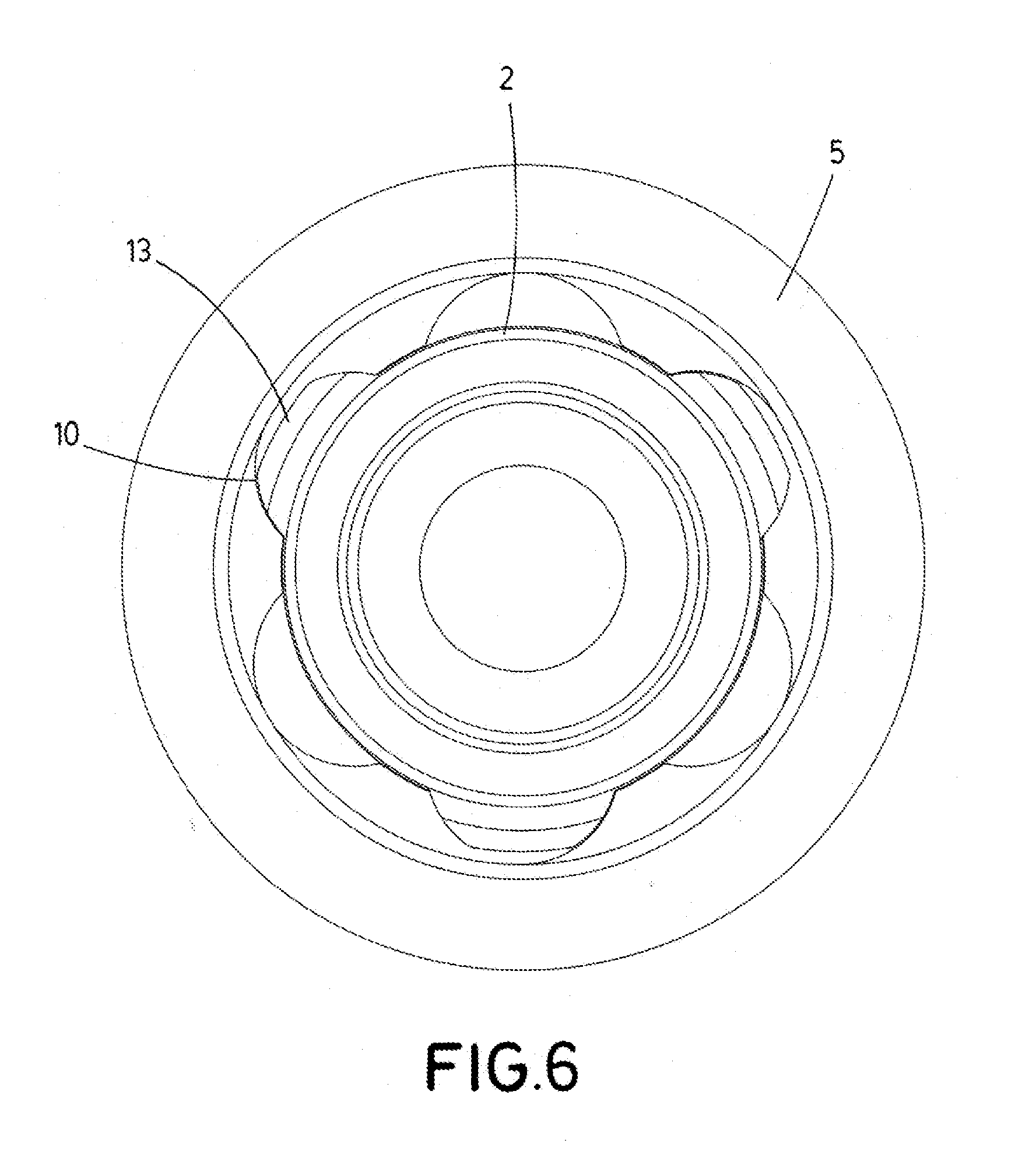
[0041] FIG. 6 shows a side view of the coupling between the lock nut of the suppressor and the muzzle brake.
PREFERRED EMBODIMENT OF THE INVENTION
[0042] What follows is a detailed description of the muzzle brake-suppressor assembly for firearms of the present invention.
[0043] The muzzle brake-suppressor assembly for firearms comprises: [0044] a muzzle brake (2) coupleable to a barrel (1) of the firearm, which barrel (1) comprises a longitudinal axis which defines an axial direction; [0045] a suppressor (3, 4, 5, 6, 7, 8, 9) coupleable to the muzzle brake (2); [0046] a system of anchoring the suppressor (3, 4, 5, 6, 7, 8, 9) to the firearm; wherein the system of anchoring the suppressor (3, 4, 5, 6, 7, 8, 9) to the firearm in turn comprises; [0047] guiding means (10) present in the suppressor (3, 4, 5, 6, 7, 8, 9) which participate with guiding means (11) present in the muzzle brake (2) and are configured for carrying out the coupling of the suppressor (3, 4, 5, 6, 7, 8, 9) to the muzzle brake (2); and [0048] first retaining means (14, 15) which are configured for preventing movement, in the axial direction, of the suppressor (3, 4, 5, 6, 7, 8, 9) with respect to the muzzle brake (2).
[0049] The muzzle brake (2) is connected to the barrel (1) of the firearm preferably by means of threading.
[0050] In this exemplary embodiment, the suppressor (3, 4, 5, 6, 7, 8, 9) comprises a lock nut (5) wherein the guiding means (10) present in the suppressor (3, 4, 5, 6, 7, 8, 9) are arranged, with these guiding means being grooves (10) arranged in the axial direction. Furthermore, the guiding means of the muzzle brake (2) comprise projections (11) in opposition with the grooves (10) of the lock nut (5) arranged in the axial direction.
[0051] Preferably, the grooves (10) of the lock nut (5) and the projections (11) of the muzzle brake (2) have at least one curved segment.
[0052] Preferably, the lock nut (5) comprises three grooves (10) and the muzzle brake (2) comprises three projections (11) in opposition with the three grooves (10).
[0053] Preferably, the three grooves (10) of the lock nut (5) and the three projections (11) of the muzzle brake (2) are equally spaced 60.degree. with respect to one another.
[0054] The grooves (10) of the lock nut (5) comprise a conical surface (12) in opposition with a conical surface (13) present in the projections (11) of the muzzle brake (2), which facilitates centering the suppressor (3, 4, 5, 6, 7, 8, 9) with respect to the muzzle brake (2), and accordingly with respect to the barrel (1) of the firearm.
[0055] Preferably, the first retaining means (14, 15) comprise at least one stop (14) present in the muzzle brake (2) in opposition with at least one projection (15) present in the suppressor (3, 4, 5, 6, 7, 8, 9) or vice versa, wherein the first retaining means (14, 15) are in an opposing position when the suppressor (3, 4, 5, 6, 7, 8, 9) has been turned a given angle with respect to the muzzle brake (2), preferably 60.degree..
[0056] The suppressor (3, 4, 5, 6, 7, 8, 9) further comprises second retaining means (4), preferably a set of washers, configured for applying pressure on the suppressor-muzzle brake connection when relative movement of at least a first element of the suppressor (3, 4, 5, 6, 7, 8, 9), preferably of an anchor body (3), with respect to a second element of the suppressor (3, 4, 5, 6, 7, 8, 9), preferably the lock nut (5), is carried out.
[0057] The suppressor (3, 4, 5, 6, 7, 8, 9) further comprises a set of deflectors (7) arranged inside a tube (6), wherein the tube (6) is connected to the anchor body (3) by connection means (9), which are preferably a threading and/or pins.
[0058] The suppressor (3, 4, 5, 6, 7, 8, 9) further comprises a cover (8) arranged at the end of the tube (6) opposite the anchor body (3).
[0059] In one exemplary embodiment, at least the suppressor (3, 4, 5, 6, 7, 8, 9) of the muzzle brake-suppressor assembly is made of plastic, preferably fungible.
[0060] What follows is a detailed description of the method of assembling a muzzle brake-suppressor assembly in a firearm.
[0061] The method of assembling the muzzle brake-suppressor assembly comprises: [0062] a step of coupling a muzzle brake (2) to a barrel (1) of a firearm, which barrel (1) comprises a longitudinal axis which defines an axial direction; [0063] a step of coupling a suppressor (3, 4, 5, 6, 7, 8, 9) to the muzzle brake (2) comprising a step of anchoring the suppressor (3, 4, 5, 6, 7, 8, 9) to the firearm, which in turn comprises the following sub-steps: [0064] a sub-step of guiding the suppressor (3, 4, 5, 6, 7, 8, 9) with respect to the muzzle brake (2), preferably in an essentially axial direction; and [0065] a first sub-step of retaining the suppressor (3, 4, 5, 6, 7, 8, 9) in the muzzle brake (2) configured for preventing movement, in the axial direction, of the suppressor (3, 4, 5, 6, 7, 8, 9) with respect to the muzzle brake (2).
[0066] The sub-step of guiding the suppressor (3, 4, 5, 6, 7, 8, 9) with respect to the muzzle brake (2) is carried out by putting a conical surface (12) of the guiding means (10) of the suppressor (3, 4, 5, 6, 7, 8, 9), arranged in a lock nut (5) in contact with a conical surface (13) in opposition present in guiding means (11) of the muzzle brake (2), which facilitates centering the suppressor (3, 4, 5, 6, 7, 8, 9) with respect to the muzzle brake (2), and accordingly with respect to the barrel (1) of the firearm.
[0067] The first sub-step of retaining the suppressor (3, 4, 5, 6, 7, 8, 9) in the muzzle brake (2) comprises a turn, in a circumferential direction of the barrel (1), of the suppressor (3, 4, 5, 6, 7, 8, 9) with respect to the muzzle brake (2), the turn preferably being a 60.degree. turn.
[0068] The step of coupling the suppressor (3, 4, 5, 6, 7, 8, 9) to the muzzle brake (2) further comprises a second step of retaining wherein pressure is applied on the suppressor-muzzle brake connection, wherein said second step of retaining comprises a step for relative movement of a first element (3) of the suppressor (3, 4, 5, 6, 7, 8, 9), preferably an anchor body (3), with respect to a second element (5) of the suppressor (3, 4, 5, 6, 7, 8, 9), preferably la lock nut (5), by means of second means of retaining (4), preferably a set of washers.
[0069] The step for relative movement of the first element (3) of the suppressor (3, 4, 5, 6, 7, 8, 9), preferably the anchor body (3), with respect to the second element (5) of the suppressor (3, 4, 5, 6, 7, 8, 9), preferably the lock nut (5), comprises a turn, in the circumferential direction of the barrel (1), of the first element (3) of the suppressor (3, 4, 5, 6, 7, 8, 9) with respect to the second element (5) of the suppressor (3, 4, 5, 6, 7, 8, 9), the turn preferably being less than 60.degree..
[0070] The method of assembling the muzzle brake-suppressor assembly further comprises a step of assembling the suppressor (3, 4, 5, 6, 7, 8, 9) prior to the step of coupling the suppressor (3, 4, 5, 6, 7, 8, 9) to the muzzle brake (2). Said step of assembling the suppressor (3, 4, 5, 6, 7, 8, 9) comprises the following sub-steps: [0071] a step of connecting an anchor body (3) of the suppressor (3, 4, 5, 6, 7, 8, 9) to the lock nut (5) of the suppressor (3, 4, 5, 6, 7, 8, 9); [0072] a step of inserting a set of deflectors (7) inside a tube (6) of the suppressor (3, 4, 5, 6, 7, 8, 9); [0073] a step of connecting the tube (6) of the suppressor (3, 4, 5, 6, 7, 8, 9) to the anchor body (3) of the suppressor (3, 4, 5, 6, 7, 8, 9); [0074] a step of connecting a cover (8) of the suppressor (3, 4, 5, 6, 7, 8, 9) at the end of the tube (6) opposite the anchor body (3).
* * * * *
D00000
D00001
D00002
D00003
D00004
D00005
D00006
XML
uspto.report is an independent third-party trademark research tool that is not affiliated, endorsed, or sponsored by the United States Patent and Trademark Office (USPTO) or any other governmental organization. The information provided by uspto.report is based on publicly available data at the time of writing and is intended for informational purposes only.
While we strive to provide accurate and up-to-date information, we do not guarantee the accuracy, completeness, reliability, or suitability of the information displayed on this site. The use of this site is at your own risk. Any reliance you place on such information is therefore strictly at your own risk.
All official trademark data, including owner information, should be verified by visiting the official USPTO website at www.uspto.gov. This site is not intended to replace professional legal advice and should not be used as a substitute for consulting with a legal professional who is knowledgeable about trademark law.