Arrangement, Particularly Refrigerating Machine Or Heat Pump
Burk; Roland
U.S. patent application number 16/325953 was filed with the patent office on 2019-07-04 for arrangement, particularly refrigerating machine or heat pump. The applicant listed for this patent is Mahle International GmbH. Invention is credited to Roland Burk.
| Application Number | 20190203990 16/325953 |
| Document ID | / |
| Family ID | 59738281 |
| Filed Date | 2019-07-04 |


| United States Patent Application | 20190203990 |
| Kind Code | A1 |
| Burk; Roland | July 4, 2019 |
ARRANGEMENT, PARTICULARLY REFRIGERATING MACHINE OR HEAT PUMP
Abstract
An arrangement may comprise a first and a second heat tank, a thermochemical reactor which is thermally and fluidically connected to the heat tank, a heat transfer fluid circuit containing a heat transfer fluid for transporting heat between the two heat tanks and the thermochemical reactor, a temporary heat store arranged in the heat transfer fluid circuit for temporarily storing the heat transfer fluid. The temporary heat store may be for receiving the heat transfer fluid has two different temperature levels. The temporary heat store may comprise a first partial store with a variable storage volume and a second partial store with a variable storage volume. The variable storage volume may be thermally and fluidically separate from the first. A valve system may be located in the heat transfer fluid circuit. The heat transfer fluid circuit may comprise at least one movable valve device, by which the heat transport between the two heat tanks, the thermochemical reactor and the temporary heat store can be controlled by the heat transfer fluid.
| Inventors: | Burk; Roland; (Stuttgart, DE) | ||||||||||
| Applicant: |
|
||||||||||
|---|---|---|---|---|---|---|---|---|---|---|---|
| Family ID: | 59738281 | ||||||||||
| Appl. No.: | 16/325953 | ||||||||||
| Filed: | August 16, 2017 | ||||||||||
| PCT Filed: | August 16, 2017 | ||||||||||
| PCT NO: | PCT/EP2017/000981 | ||||||||||
| 371 Date: | February 15, 2019 |
| Current U.S. Class: | 1/1 |
| Current CPC Class: | F25B 25/005 20130101; F25B 41/04 20130101; F28D 2020/0095 20130101; F25B 30/04 20130101; F28D 20/0034 20130101; F25B 2400/24 20130101; F25B 49/046 20130101; F25B 17/08 20130101 |
| International Class: | F25B 41/04 20060101 F25B041/04; F25B 17/08 20060101 F25B017/08; F25B 25/00 20060101 F25B025/00; F25B 49/04 20060101 F25B049/04; F28D 20/00 20060101 F28D020/00 |
Foreign Application Data
| Date | Code | Application Number |
|---|---|---|
| Aug 17, 2016 | DE | 102016215368.4 |
Claims
1. A system for an arrangement of a refrigerating machine or heat pump, comprising: a first heat tank functioning as heat source and with a second heat tank functioning as heat sink; a thermochemical reactor including an adsorption refrigerating machine or an adsorption heat pump, which is connectible or connected thermally and fluidically to the heat tanks; a heat transfer fluid circuit in which a heat transfer fluid is arranged for transporting heat between the two heat tanks and the thermochemical reactor; a temporary heat store arranged in the heat transfer fluid circuit for temporarily storing the heat transfer fluid, wherein the temporary heat store is designed to receive the heat transfer fluid with two different temperature levels and for this purpose has a first partial store with variable storage volume and a second partial store with variable storage volume which is thermally and fluidically separated therefrom; a transport device located in the heat transfer fluid circuit for propelling the heat transfer fluid (F) in the heat transfer fluid circuit; a valve system (9) comprising at least one displaceable valve device including two displaceable valve devices provided in the heat transfer fluid circuit, wherein the transport of heat between the two heat tanks, the thermochemical reactor and the temporary heat store can be controlled via the heat transfer fluid; and a control/regulating device for controlling the valve system.
2. The system according to claim 1, wherein the temporary heat store is designed to receive and discharge a first and a second fluid mass of the heat transfer fluid simultaneously, wherein the two fluid masses have different temperature levels.
3. The system according to claim 1, wherein the first partial store of the temporary heat store is connected fluidically to the first heat tank and the second partial store of the temporary heat store is connected fluidically to the second heat tank.
4. The system according to claim 1, wherein the volume-variable first partial store is designed to complement the volume-variable second partial store, so that the total volume formed by the two partial stores is constant.
5. The system according to claim 1, wherein the temporary heat store is embodied as a receptacle wherein the receptacle comprises: a housing with an interior space of which a dividing element is arranged so as to be movable and which divides the interior space into a volume-variable first partial store and a second partial store which is also volume-variable and is insulated thermally from the first partial store, a first aperture in the housing for introducing a heat transfer fluid with a first temperature level into the first partial store and discharging the heat transfer fluid therefrom, and a second aperture in the housing for introducing a heat transfer fluid with a first temperature level into the second partial store and discharging it the heat transfer fluid therefrom, wherein the volume-variable first partial store is designed to complement the volume-variable second partial store, so that the total volume formed by the two partial stores is constant.
6. The system according to claim 5, wherein the housing is of an elongated construction, wherein the first aperture is located at a first longitudinal end and the second aperture is located at a second longitudinal end opposite the first longitudinal end.
7. The system according to claim 5, wherein the housing is constructed as a tubular body which extends substantially linearly in an axial direction wherein the dividing element lies against a circumferential wall of the tubular body and is movable in the axial direction along the inner side thereof to form the two volume-variable partial stores.
8. The system according to any one of claim 5, wherein at least one of: a first sensor element s provided at the first aperture, and by means of which it can be determined whether the dividing element is in a first end position in which the dividing element is at a minimum distance from the first aperture, and, and a second sensor element is provided at the second aperture, by which it can be determined whether the dividing element is in a second end position in which the dividing element is at a minimum distance from the second aperture.
9. The system according to claim 1, wherein an operating state can be set by the control/regulating device in the at least one displaceable valve device of the valve system, in which state the heat transfer fluid circuit forms a first partial circuit, in which the heat transfer fluid circulates between the thermochemical reactor and the second heat tank so that heat is transferred from the thermochemical reactor into the second heat tank.
10. The system according to claim 9, wherein in this operating state the first partial store has a maximum volume and the second partial store has a minimum volume.
11. The system according to claim 1, wherein an operating state can be set by the control/regulating device in the at least one displaceable valve device of the valve system, in which state the heat transfer fluid circuit forms a second partial circuit, in which the heat transfer fluid circulates between the thermochemical reactor and the first heat tank so that heat is transferred from the first heat tank into the thermochemical reactor.
12. The system according to claim 11, wherein in this operating state the second partial store has a maximum volume and the first second partial store has a minimum volume.
13. The system according to claim 1, wherein an operating state can be set by the control/regulating device in the at least one displaceable valve device of the valve system, wherein: heat transfer fluid is transported from the first partial store into the first heat tank, heat transfer fluid is transported from the first heat tank into the thermochemical reactor, and heat transfer fluid is transported from the thermochemical reactor into the second partial store.
14. The system according to claim 1, wherein an operating state can be set by the control/regulating device in the at least one displaceable valve device of the valve system, in wherein: heat transfer fluid is transported from the second partial store into the second heat tank, heat transfer fluid is transported from the second heat tank into the thermochemical reactor, and heat transfer fluid is transported from the thermochemical reactor into the first partial store.
15. The system claim 1, wherein the first and the second heat tanks and the thermochemical reactor are each equipped with a fluid inlet and a fluid outlet to enable the heat transfer fluid to be introduced therein and discharged therefrom, wherein: the fluid inlet of the thermochemical reactor can be connected selectively to the fluid outlet of the first or second heat tank by the first displaceable valve device, and the fluid outlet of the thermochemical reactor can be connected selectively to the fluid inlet of the first or second heat tank by the second displaceable valve device.
16. The system according to claim 1, wherein the temporary heat store is connected fluidically in parallel with the second valve device, so that the fluid inlet of the first heat tank communicates fluidically with the first partial store and der fluid inlet of the second heat tank communicates fluidically with the second partial store.
17. The system according to claim 1, wherein the first valve device and the second valve device each comprise a 3-port/2-position switching valve.
18. A method for operating an arrangement of a refrigerating machine or heat pump, comprising: providing a heat transfer fluid circuit in which a thermochemical reactor, two heat tanks with different temperature levels and a temporary heat store are disposed, wherein the temporary heat store includes two thermally and fluidically separate partial stores, in which a heat transfer fluid present in the heat transfer fluid circuitcan be received thermally and fluidically separately from each other; removing a heating process heat transfer fluid, temporarily stored in the first partial store of the temporary heat store, is removed from the first heat tank into the thermochemical reactor by the heat transfer fluid, and into the first heat tank while heat transfer fluid is discharged from the thermochemical reactor and into the second partial store of the temporary heat store and removing a cooling process heat transfer fluid, temporarily stored in the second partial store of the temporary heat store, from the thermochemical reactor and into the second heat tank by the heat transfer fluid in the second partial store while heat transfer fluid (F) is discharged from the thermochemical reactor and introduced into the first partial store of the temporary heat store.
19. The method of claim 18, further comprising: providing a housing with an interior space and a dividing element arranged in the interior space; providing a first sensor element at the first aperture to determine whether the dividing element is in a first end position in which the dividing element is at a first minimum distance from the first aperture; and providing a second sensor element at the second aperture to determine whether the dividing element is in a second end position in which the dividing element is at a second minimum distance from the second aperture.
20. The method of claim 18, further comprising: transporting heat transfer fluid from the first partial store into the first heat tank; transporting heat transfer fluid from the first heat tank into the thermochemical reactor; and transporting heat transfer fluid from the thermochemical reactor into the second partial store.
Description
CROSS-REFERENE TO RELATED APPLICATIONS
[0001] This application claims priority to International Application PCT/EP2017/000981 filed on Aug. 16, 2017, and to German Application DE 10 2016 215 368.4 filed on Aug. 17, 2016, the contents of each are hereby incorporated by reference in their entirety.
TECHNICAL FIELD
[0002] The invention relates to an arrangement, particularly a refrigerating machine or heat pump, and a method for operating said arrangement.
[0003] Thermochemically driven sorption refrigeration systems have potential for substantial energy conservation, since inexpensive waste or surplus heat is used as operating energy, thus making it possible to economise on expensive mechanical operating energy. In fixed position applications, a substantial burden can be removed from electrical networks particularly in warm time and climate zones with a substantial cooling requirement. During the cold season, the plants can also function as heat pumps which use burner heat to raise additional environmental heat to a temperature level which is adequate for heating purposes.
BACKGROUND
[0004] Against this background, devices are known from the related art in which porous solid materials are used, reacting with a working material for implementing heat, and which have no moving parts that are consequently susceptible to wear and failure in the working material area.
[0005] However, the disadvantage of adsorption heat pumps or adsorption refrigeration systems which function with the aid of such thermochemical reactors compared with continuously operating adsorption systems is that the periodic temperature changes associated with cycled thermal masses result in efficiency losses, which reduce the power density and power efficiency obtained by the adsorption heat pumps and adsorption refrigeration system.
[0006] In this context, DE 10 2006 043 715 A1 discloses an adsorption heat pump which uses a stratified heat store.
[0007] This enables both sensible and latent heat to be stored and reused with a time delay during the adsorption cycle.
[0008] One problem addressed by the present invention is to describe new ways in the development of sorption heat pumps and/or sorption refrigeration systems, particularly with improved efficiency.
[0009] This problem is solved with the object of the independent claims. Preferred variants are objects of the dependent claims.
SUMMARY
[0010] Accordingly, the basic idea of the invention is to equip a thermochemical reactor for creating an adsorption heat pump or adsorption refrigerating machine--in the present case with a temporary heat store which has two partial stores for receiving a heat transfer fluid having two different temperature levels. This temporary heat store serves to temporarily store heat contained in the heat transfer fluid during the thermal cycling of the thermochemical reactor and the switching of the reactor between two different temperature levels associated therewith. The term "thermochemical reactor" is understood to refer in broader terms to a container having a least one working material and an integrated heat transfer structure, with which an exothermic or endothermic reaction or phase transformation can be initiated by removing and/or introducing heat depending on at least one temperature boundary condition. Accordingly, it may be a sorption reactor or a phase transformer, particularly a condenser and/or vaporiser. More specific variants, components and/or sub-components of such kind are also known by the terms "sorber", "sorption reactor", "thermochemical store" or "phase transformer".
[0011] The temporary heat store used in the present case, which is essential for the invention, allows temporary storage of the heat transfer fluid at the temperature level of one heat source of the arrangement in the first partial store and simultaneous temporary storage of the heat transfer fluid at the temperature level of a heat sink of the arrangement in the second partial store of the temporary heat store.
[0012] An increase in the volume of the first partial store in the temporary heat store that is essential to the invention automatically induces an decrease in the volume of the second partial store and vice versa. Since the overall volume of the two variable volume partial stores remains unchanged, introducing the heat transfer fluid at the temperature level of the heat source into the first partial chamber facilitates the discharge of the heat transfer fluid at the second temperature level from the second partial store and vice versa. In this way, it is possible to minimise undesirable energy losses from the thermochemical reactor during thermal cycling, that is to say when switching between the two temperature levels of the heat source and the heat sink. Consequently, this results in improved efficiency of the arrangement according to the invention compared with conventional arrangements.
[0013] An arrangement according to the invention, particularly a refrigerating machine or a heat pump, comprises a first heat tank, which functions as a heat source, and a second heat tank, which functions as a heat sink. The arrangement further comprises a thermochemical reactor which is thermally and fluidically connectable or connected to the heat tanks. The thermochemical reactor is preferably an essential component of an adsorption refrigerating machine or an adsorption heat pump.
[0014] The arrangement further comprises a heat transfer fluid circuit, in which a heat transfer fluid is provided for transporting heat between the two heat tanks and the thermochemical reactor. A temporary heat store for temporary storage of temperature-controlled heat transfer fluid is provided in the heat transfer fluid circuit. According to the invention, the temporary heat store has a first partial store with variable storage volume. The temporary heat store further has a second partial store with variable storage volume which is thermally and fluidically separate from the first partial store.
[0015] A transport device of the arrangement according to the invention which is present in the heat transfer fluid circuit serves to move the heat transfer fluid in the heat transfer fluid circuit. The arrangement further comprises a valve system located in the heat transfer fluid circuit, which valve system includes at least one displaceable valve device. With this at least one displaceable valve device, it is possible to control the transport of heat between the two heat tanks, the thermochemical reactor and the temporary heat store via the heat transfer fluid. Finally, the arrangement according to the invention comprises a control/regulating device for controlling said valve system.
[0016] In a preferred embodiment, the temporary heat store is designed to receive and discharge a first and a second fluid mass of the heat transfer fluid simultaneously, wherein the two fluid masses have different temperature levels. This makes it possible to temporarily store a fluid mass with the temperature level of the heat source and a fluid mass with the temperature level of the heat sink in the temporary heat store at the same time.
[0017] Particularly preferably, the first partial store of the temporary heat store is connected fluidically to the first heat tank and the second partial store of the temporary heat store is connected fluidically to the second heat tank. This arrangement enables heat transfer fluid stored in the temporary store at the temperature level of the heat source to be returned easily to the first heat tank. This arrangement also enables transfer fluid stored in the temporary store at the temperature level of the heat sink to be returned easily to the second heat tank.
[0018] According to a particularly preferred embodiment, the temporary heat store is embodied as a receptacle. In this variant, the receptacle comprises a housing with a dividing element arranged so as to be movable in the interior thereof, which element divides the interior into a volume-variable first partial store and a second partial store which is also volume-variable and is thermally insulated from the first partial store. A first aperture is provided in the housing to channel the heat transfer fluid into the first partial store and channel it out of the first partial store. A second aperture is also provided in the housing to channel the heat transfer fluid into the second partial store and channel it out of the second partial store.
[0019] In an advantageous further development, the housing is of elongated construction. In this context, the first aperture is located on a first longitudinal end and the second aperture is located on a second longitudinal end opposite the first longitudinal end. The large length to cross-section ratio which is associated with an elongated construction of the housing serves the purpose of ensuring that a temperature stratification of the fluid mass flowing in and out is largely preserved and no significant mixing thereof occurs during the necessary storage time.
[0020] The housing may expediently be designed as a tubular body which extends substantially linearly in an axial direction. In this variant, the dividing element for creating the two volume-variable partial stores fits against the inner side of the circumferential wall of the tubular body so as to be movable in the axial direction thereof. Such a structure is technically easy to manufacture and is thus associated with low production costs.
[0021] In another advantageous further development, a first sensor element is provided at the first aperture and serves to determine whether the dividing element is in a first end position, in which the dividing element has a minimum separation from the first aperture. Alternatively or additionally, in this variant a second sensor element may be provided as the second aperture, and may serve to determine whether the dividing element is in a second end position, in which the dividing element has a minimum separation from the second aperture. This makes it possible to detect when the heat transfer fluid has been completely removed from one of the two partial stores during thermal cycling of the thermochemical reactor; because in this case the dividing element is positioned at a minimal distance from the first or second aperture.
[0022] In a preferred embodiment of the arrangement, the control/regulating device in the at least one displaceable valve device of the valve system is able to set an operating state in which the heat transfer fluid circuit forms a first partial circuit. In the first partial circuit, the heat transfer fluid circulates between the thermochemical reactor and the second heat tank so that the heat from the thermochemical reactor is transferred to the second heat tank, that is to say to the heat sink. In this way, heat may be transported away from the thermochemical reactor particularly effectively.
[0023] In this operating state, the first partial store preferably has a maximum volume and the second partial store has a minimum volume. This means that the first partial store is filled with the heat transfer fluid, which has substantially the temperature level of the heat source.
[0024] In a further preferred embodiment of the arrangement, the control/regulating device in the at least one displaceable valve device of the valve system is able to set an operating state in which the heat transfer fluid circuit forms a second partial circuit. In this second partial circuit the heat transfer fluid circulates between the thermochemical reactor and the first heat tank so that heat is transferred from the first heat tank, that is to say from the heat source into the thermochemical reactor.
[0025] In this operating state, the second partial store preferably has a maximum volume and the first partial store has a minimum volume. This means that the second partial store is filled with the heat transfer fluid, which has substantially the temperature level of the heat sink.
[0026] In a further preferred embodiment of the arrangement, the control/regulating device in the at least one displaceable valve device of the valve system is able to set an operating state in which heat transfer fluid is transported from the first partial store of the temporary heat store into the first heat tank. At the same time, heat transfer fluid is transported from the first heat tank into the thermochemical reactor and heat transfer fluid is transported from the thermochemical reactor into the second partial store. In this way, heat may be introduced into the thermoelectric reactor particularly effectively in order to raise the temperature from a low level to a higher level. In the following text, this process will therefore be referred to as the heating process.
[0027] In a further preferred embodiment of the arrangement, the control/regulating device in the at least one displaceable valve device of the valve system is able to set an operating state in which heat is transported from the second partial store to the second heat tank by means of the heat transfer fluid. At the same time, heat is transported from the second heat tank into the thermochemical reactor and from the thermochemical reactor into the first partial store by means of the heat transfer fluid. In this way, heat may be removed from the thermoelectric reactor particularly effectively in order to lower the temperature from a high level to a lower level. In the following text, this process will therefore be referred to as the cooling process.
[0028] In an advantageous further development, the first and the second heat tanks as well as the thermochemical reactor are each equipped with a fluid inlet and a fluid outlet to enable the heat transfer fluid to be introduced into them and discharged therefrom. In this variant, the heat transfer fluid circuit comprises a first displaceable valve device, by means of which the fluid inlet of the thermochemical reactor may be connected selectively with the fluid outlet of the first or the second heat tank. In the same way, the heat transfer fluid circuit comprises a second displaceable valve device, by means of which the fluid outlet of the thermochemical reactor may be connected selectively with the fluid inlet of the second heat tank.
[0029] The temporary heat store is expediently connected fluidically in parallel with the second valve device, so that the fluid inlet of the first heat tanks is in fluidic communication with the first partial store and the fluid inlet of the second heat tank is in fluidic communication with the second partial store.
[0030] In an advantageous further development, the first valve device and the second valve device each comprise a 3-port/2-position switching valve.
[0031] The invention further relates to a method for operating an arrangement, preferably an arrangement such as was described in the preceding text with a heat transfer fluid circuit in which a thermochemical reactor, two heat tanks of different temperatures and a temporary heat store are arranged and are connected to each other fluidically via a heat transfer fluid circuit.
[0032] The temporary heat store used to carry out the method according to the invention has two thermally and fluidically separated partial stores, in which a heat transfer fluid circulating in the heat transfer fluid circuit may be taken up thermally and fluidically separately from each other.
[0033] According to the inventive method, for a heating process heat transfer fluid stored temporarily at a higher temperature is taken from the first partial store of the temporary heat store and introduced into the thermochemical reactor via the first heat tank. At the same time, heat transfer fluid at a lower temperature discharged from the thermochemical reactor is transported away and introduced into the second partial store of the temporary heat store. For a cooling process, heat transfer fluid stored temporarily at a lower temperature is taken from the second partial store of the temporary heat store and introduced into the thermochemical reactor via the second heat tank. At the same time, heat transfer fluid at a higher temperature discharged from the thermochemical reactor is transported away and introduced into the first partial store of the temporary heat store. By using the temporary heat store which is essential to the invention, heat is stored temporarily to effect a temperature change and reused for the respective reciprocal temperature change.
[0034] Further important features and advantages of the invention will be evident from the subclaims, the drawing and the associated description of the figures with reference to the drawing.
[0035] Of course, the features presented in the preceding text and those that will be explained subsequently are usable not only in the respective described combinations but also in other combinations or alone without departing from the scope of the present invention.
[0036] Preferred embodiments of the invention are represented in the drawings and will be explained in greater detail in the following description, in which the same reference signs refer to identical or similar or functionally equivalent components.
BRIEF DESCRIPTION OF THE DRAWINGS
[0037] In the schematic drawings:
[0038] FIGS. 1 to 4 show an arrangement according to the invention in different operating states,
[0039] FIG. 5 shows a detail view of the construction of the temporary heat store which is essential to the invention of the arrangement of FIGS. 1 bis 4,
[0040] FIG. 6 shows a first variant of the temporary heat store of FIG. 5,
[0041] FIG. 7 shows a second variant of the temporary heat store of FIG. 5.
DETAILED DESCRIPTION
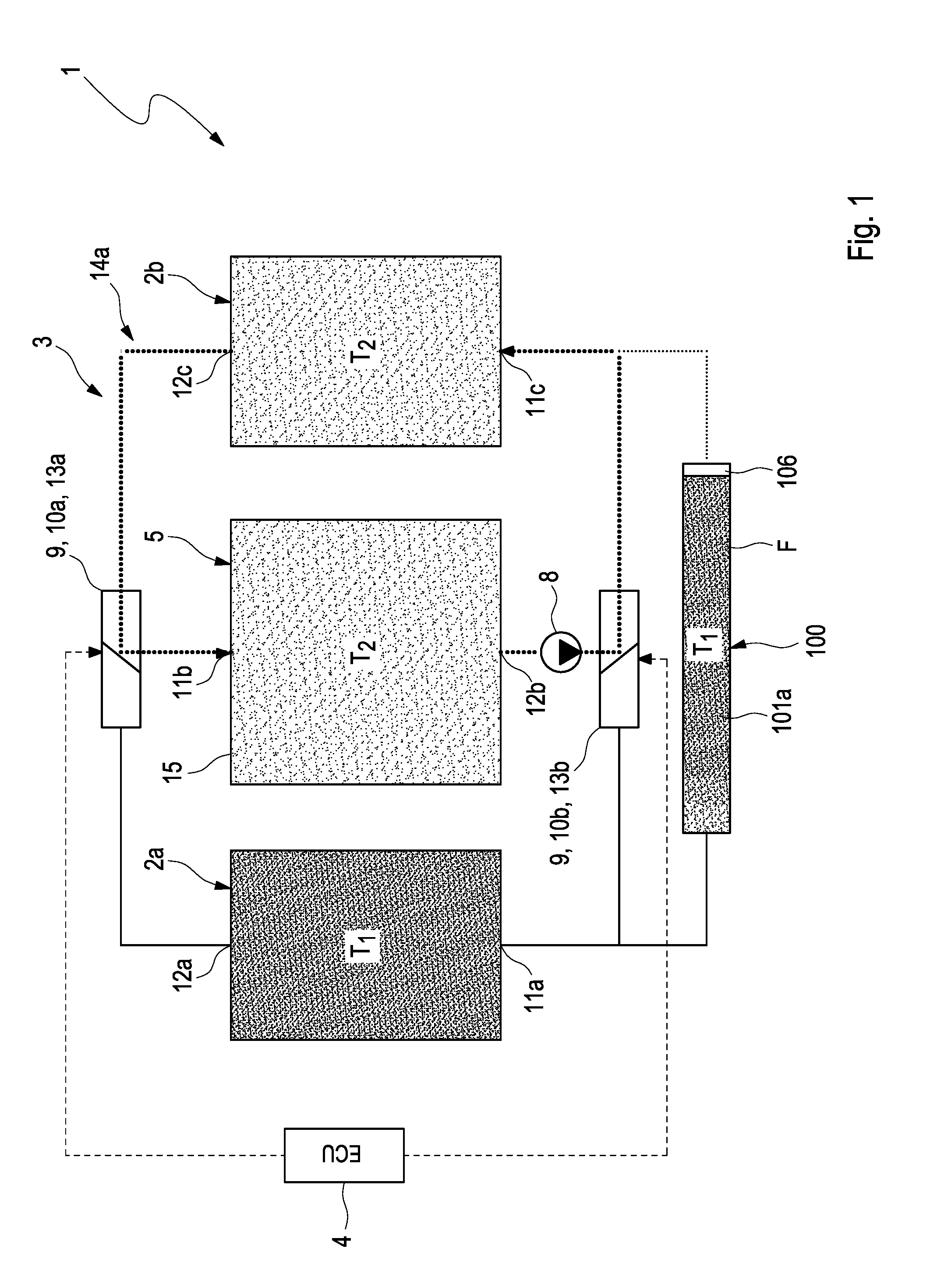
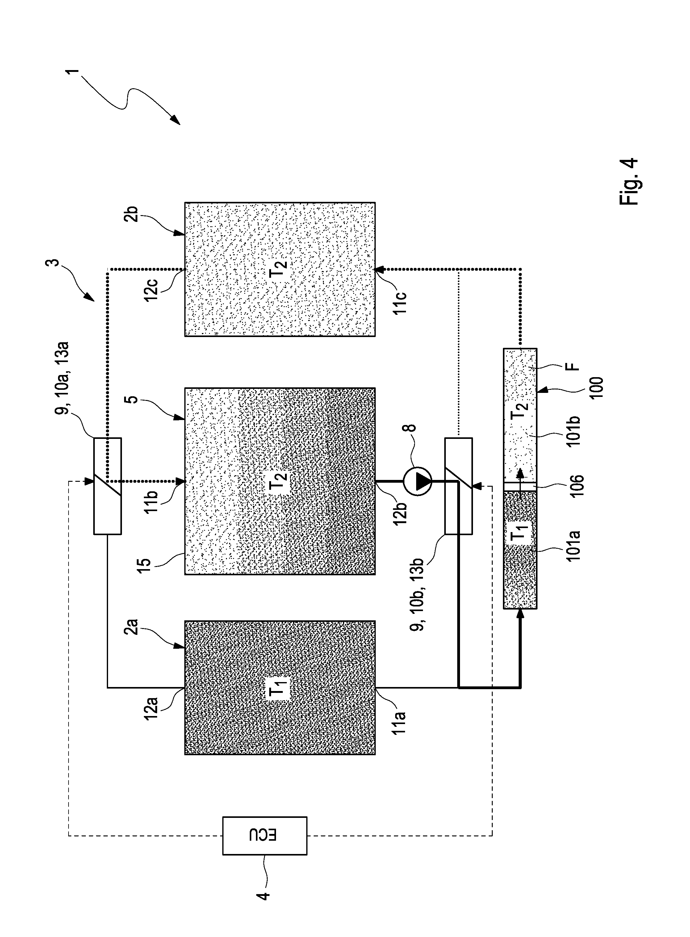
[0042] FIG. 1 shows an example of an arrangement 1 according to the invention, particularly a refrigerating machine or a heat pump. The arrangement 1 comprises a first heat tank 2a with a first temperature T.sub.1 and a second heat tank 2b with a second temperature T.sub.2. The arrangement 1 further comprises a thermochemical reactor 5 which is or may be connected thermally and fluidically to the two heat tanks 2a, 2b. For this purpose, the arrangement 1 comprises a heat transfer fluid circuit 3, in which a heat transfer fluid F is located for transporting heat between the two heat tanks 2a, 2b and the thermochemical reactor 5.
[0043] In the present context, the term "thermochemical reactor" is understood to refer to an apparatus in which transformation processes are initiated at different temperatures T.sub.1, T.sub.2 by the introduction and removal of heat--known to the person skilled in the art as reaction heat or sorption heat. The thermochemical reactor 5 may include a receptacle 15, only indicated schematically in the figures, in which thermochemical reactions take place. The first temperature T.sub.1 has a larger value than the second temperature T.sub.2, i.e. the first heat tank 2a functions as the heat source, from which heat may be transferred to the thermochemical reactor 5 by means of the heat transfer fluid F. In contrast, the second heat tank 2b functions as a heat sink, to which heat may be transferred from the thermochemical reactor 5 by means of the heat transfer fluid F.
[0044] A temporary heat store 100 is also present in the heat transfer fluid circuit 3 for temporarily storing the heat transfer fluid F. The temporary heat store 100 cooperates with the two heat tanks 2a, 2b to enable a temperature change of the thermochemical reactor 5 from temperature T.sub.1 to temperature T.sub.2 and vice versa with very low energy losses.
[0045] The construction of the temporary heat store 100 is shown in a detail schematic representation in FIG. 5. According to FIG. 5, the temporary heat store 100 includes a first partial store 101a with variable storage volume 102a, and a second partial store 101b with variable storage volume 102b which is thermally and fluidically separated from therefrom. The volume-variable first partial store 101a of the temporary heat store 100 is constructed to complement the volume-variable second partial store 101b, so that the overall volume contained by the two partial stores 101a, 101b is constant.
[0046] The temporary heat store 100 may also be described as a short duration sensible heat store, a regenerator or a temperature variator and constitutes a component of arrangement 1 that is essential to the invention, being indispensable for enabling temperature change with low energy losses to be made at all in the thermochemical reactor 5.
[0047] The temporary heat store 100 is designed to be able to take up and discharge a first and a second fluid mass of the heat transfer fluid F at different temperatures simultaneously. The temporary heat store 100 is also designed to take up and discharge the first and a second fluid mass of the heat transfer fluid F simultaneously wherein the two masses have different temperature levels. The temporary heat store 100 is further designed in such manner that temperature stratifications introduced in the flow direction are preserved for the period between the delivery of fluid masses to the store and their removal therefrom.
[0048] As illustrated in FIG. 1, the first partial store 101a of the temporary heat store 100 is connected fluidically to the first heat tank 2a. On the other hand, the second partial store 101b of the temporary heat store 100 connected fluidically to the second heat tank 2b.
[0049] The functional principle of the temporary heat store 100 is based on a thermally insulated fluid container with apertures at the ends thereof and a large length to cross-section ratio within which an displaceable insulating separating element is arranged, as is shown schematically in FIG. 5.
[0050] In the exemplary scenario of FIG. 5, the temporary heat store 100 is embodied as receptacle 103. This receptacle 103 comprises a housing 104. The housing 104 delimits an interior space 107 in which a dividing element 106 is arranged movably and which isolates the two partial stores 101a, 101b from each other thermally and fluidically. The dividing element 106 divides the interior space 107 into a volume-variable first partial store 101a and a second partial store 101b which is also volume-variable and is isolated thermally and fluidically from the first partial store 101a. Dividing element 106 of the temporary heat store 100 is advantageously designed such that it is easily movable due to pressure differences between the partial stores and efficiently seals the two partial stores off from each other.
[0051] As the figures show, the thermochemical reactor 5 and the temporary heat store 100 are each equipped with separate receptacles 15 and 103 respectively.
[0052] As may be seen in FIG. 5, a first aperture 108a is present in the housing 104 to deliver the heat transfer fluid F at temperature T.sub.1 into the first partial store 101a and remove it from the first partial store 101a. The housing 104 further has a second aperture 108b to deliver the heat transfer fluid F at temperature T.sub.2 into the second partial store 101b and remove it from the second partial store 101b.
[0053] The housing 104 is embodied as a tubular body 105 which extends linearly in an axial direction A. The dividing element 106 lies against the inner side 112 of a circumferential wall 111 of the tubular body 105 to form the two volume-variable partial stores 101a, 101b and is movable in the axial direction A. The first aperture 108a is located on a first longitudinal end 109a. The second aperture 108b is located on a second longitudinal end 109b opposite the first longitudinal end 109a.
[0054] As is illustrated in FIG. 5, when the dividing element 106 is positioned in the extreme left position, that is to say t at the first aperture 108a, the temporary heat store 100 may be filled with "cold" heat transfer fluid F at temperature T.sub.2. The dividing element 106 may be displaced to the right, towards the second aperture 108b by hot heat transfer fluid F at temperature T.sub.1 flowing in from the left through the first aperture 108a, so that the temporary heat store 100 is filled with heat transfer fluid F at temperature T.sub.1. At the same time, heat transfer fluid F at temperature T.sub.2 is discharged to the right through the second aperture 108b until the dividing element 106 is positioned at the second aperture 108b and the heat transfer fluid F at temperature T.sub.2 has been entirely displaced by the hot heat transfer fluid F at temperature T.sub.1 without mixing therewith.
[0055] A first sensor element 110a is provided at the first aperture, with which it is possible to determine whether the dividing element 106 is in a first end position, in which it is at a minimum distance from the first aperture 108a. In similar manner, a second sensor element 110b is provided at the second aperture 108b, with which it is possible to determine whether the dividing element 106 is in a second end position, in which it is at a minimum distance from the second aperture 108b.
[0056] If one then considers FIG. 1 again, it may be seen that a transport device 8 is provided in the heat transfer fluid circuit 3 to propel the heat transfer fluid F around the heat transfer fluid circuit 3.
[0057] The heat transfer fluid circuit 3 is also equipped with a valve system 9 which comprises a first displaceable valve device 10a and a second displaceable valve device 10b. It is possible to adjust and consequently also control the transport of heat between the two heat tanks 2a, 2b, the thermochemical reactor 5 and the temporary heat store 100 by means of the two valve devices 10a, 10b. A control/regulating device 4 which cooperates with the valve devices 10a, 10b is provided for controlling the valve devices 10a, 10b of the valve system 9.
[0058] The first and the second heat tanks 2a, 2b and the thermochemical reactor 5 each have a fluid inlet 11a, 11b, 11c for introducing the heat transfer fluid F and a fluid outlet 12a, 12b, 12c for discharging the heat transfer fluid.
[0059] The fluid inlet 11b of the thermochemical reactor 5 may be connected selectively to the fluid outlet 12a, 12c of the first or second heat tank 2a, 2b by means of the first displaceable valve device 10a. The fluid outlet 12b of the thermochemical reactor 5 may be connected selectively to the fluid inlet 11a, 11c of the first or second heat tank 2a, 2b by means of the second displaceable valve device 10b.
[0060] As may further be seen in FIG. 1, the temporary heat store 100 is fluidically connected in parallel with the second valve device 10b, so that the fluid inlet 1 la of the first heat tank 2a communicates fluidically with the first partial store 101a, and the fluid inlet 11c of the second heat tank 2b communicates fluidically with the second partial store. The first valve device 10a and the second valve device 10b are each designed as 3-port/2-position switching valves 13a, 13b.
[0061] The following text will now describe a complete thermal cycle of the thermochemical reactor 5, in which the thermochemical reactor 5 is switched between a first state with temperature T.sub.1 of the first heat tank 2a and a second state with temperature T.sub.2 of the second heat tank 2b.
[0062] The two valve devices 10a, 10b of the valve system 9 may be shifted into an operating state shown schematically in FIG. 1 by the control/regulating device 4. In this operating state, the first partial store 101a has a maximum volume and the second partial store 101b has a minimal volume, i.e., the first partial store 101a of the temporary heat store 100 is filled with heat transfer fluid F at temperature T.sub.1 and the second partial store 101b is empty. In this operating state, the heat transfer fluid circuit 3 forms a first partial circuit 14a, in which the heat transfer fluid F circulates between the thermochemical reactor 5 and the second heat tank 2b. In this operating state, the heat transfer fluid F transfers heat from the thermochemical reactor 5 to the second heat tank 2b, i.e., heat is taken out of the thermochemical reactor 5. As a consequence of this transport of heat from the thermochemical reactor 5 into the second heat tank 2b, reaction heat of the thermochemical reactor 5 is directed away to the second heat tank at temperature T.sub.2.
[0063] As the thermal cycling progresses, the thermochemical reactor 5 is then switched into a state with temperature T.sub.1 of the first heat tank 2a. In order to switch the thermochemical reactor into a state with temperature T.sub.1, the two valve devices 10a, 10b are first shifted into an operating state shown in FIG. 2 by the control/regulating device 4. In the operating state shown in FIG. 2, the two valve devices 10a, 10b are adjusted in such manner that heat transfer fluid F is transported from the first partial store 101a of the temporary heat store 100 into the first heat tank 2a. Heat transfer fluid F is also transported from the first heat tank 2a into the thermochemical reactor 5. In addition, heat transfer fluid F is transported from the thermochemical reactor 5 into the second partial store 101b. In this operating state, the first partial store 101a of the temporary heat store 100 is full of heat transfer fluid F at temperature T.sub.1 and the second partial store 101b is full of heat transfer fluid F at temperature T.sub.2. In this operating state, the temperature of the thermochemical reactor is raised from T.sub.2 to T.sub.1, without removing a significant amount of heat from the heat source 2a.
[0064] As soon as the heat transfer fluid F stored temporarily in the first partial store 101a of the temporary heat store 100 has been completely removed from the temporary heat store 100, the dividing element 106 is located in the aforementioned first end position, which may be detected by the control/regulating device 4 by means of the first sensor element 110a.
[0065] Then, the two valve devices 10a, 10b are switched to an operating state as represented schematically in FIG. 3 by the control/regulating device 4.
[0066] In the operating state as represented schematically in FIG. 3, the heat transfer fluid circuit 3 forms a second partial circuit 14b, in which the heat transfer fluid F circulates between the thermochemical reactor 5 and the first heat tank 2a. In this way, heat transfer fluid F is transported from the first heat tank 2a to the thermochemical reactor. In this operating state, heat is transferred from the first heat tank to the thermochemical reactor 5. In this operating state, the second partial store 101b has a maximum volume and the first partial store 101a has a minimum volume, i.e., the second partial store 101b of the temporary heat store 100 is filled with heat transfer fluid F at temperature T.sub.2 and the first partial store 101b is empty. In this operating state, heat transfer fluid is transferred to the thermochemical reactor via the heat tank at temperature level T.sub.1.
[0067] Then, the two valve devices 10a, 10b are switched to an operating state as represented schematically in FIG. 4 by the control/regulating device 4. In the operating state represented in FIG. 4, both valve devices 10a, 10b are set in such manner that heat is transported from the second partial store 101b into the second heat tank 2b by means of the heat transfer fluid F. At the same time, heat from the thermochemical reactor 5 is transported into the first partial store 101a of the temporary heat store 100. In this operating state, the temperature of the thermochemical reactor is reduced from T.sub.1 to T.sub.2 without a significant quantity of heat being direct to the heat sink 2b.
[0068] As soon as the heat transfer fluid F stored temporarily in the second partial store 101b of the temporary heat store 100 has been completely removed from the temporary heat store 100, the dividing element 106 is located in the aforementioned second end position, which may be detected by the control/regulating device 4 with the aid of the second sensor element 110b. In this state, the first partial store 101a is completely full of heat transfer fluid F (see FIG. 1). The two valve devices 10a, 10b are switched back to the operating state shown in FIG. 1 by the control/regulating device 4 and one complete switching cycle of the thermochemical reactor 5 is complete.
[0069] FIG. 6 shows a further development of the receptacle 103 of FIG. 5. In the receptacle 103 of FIG. 6, a spiral structure 113 is disposed in the interior space 107 of the housing 104. This spiral structure 113 lends the interior space 107 the geometry of a fluid duct 114 with spiral geometry. The fluid duct 114 is delimited by the spiral structure 113 and by the housing 104, particularly the circumferential wall 111 thereof. The spiral structure 103 may be embodied as an insert 115 disposed in the interior space. The spiral structure 113 may comprise at least ten windings 116, preferably even at least 20 windings. The dividing element 106 is designed so as to be displaceable, particularly slidable along the spiral fluid duct 114. This means that the geometrical shape of the dividing element 106 is selected such that it is displaceable along the fluid duct 114 in the interior space 107 which is delimited by the circumferential wall 111 and the spiral structure 113.
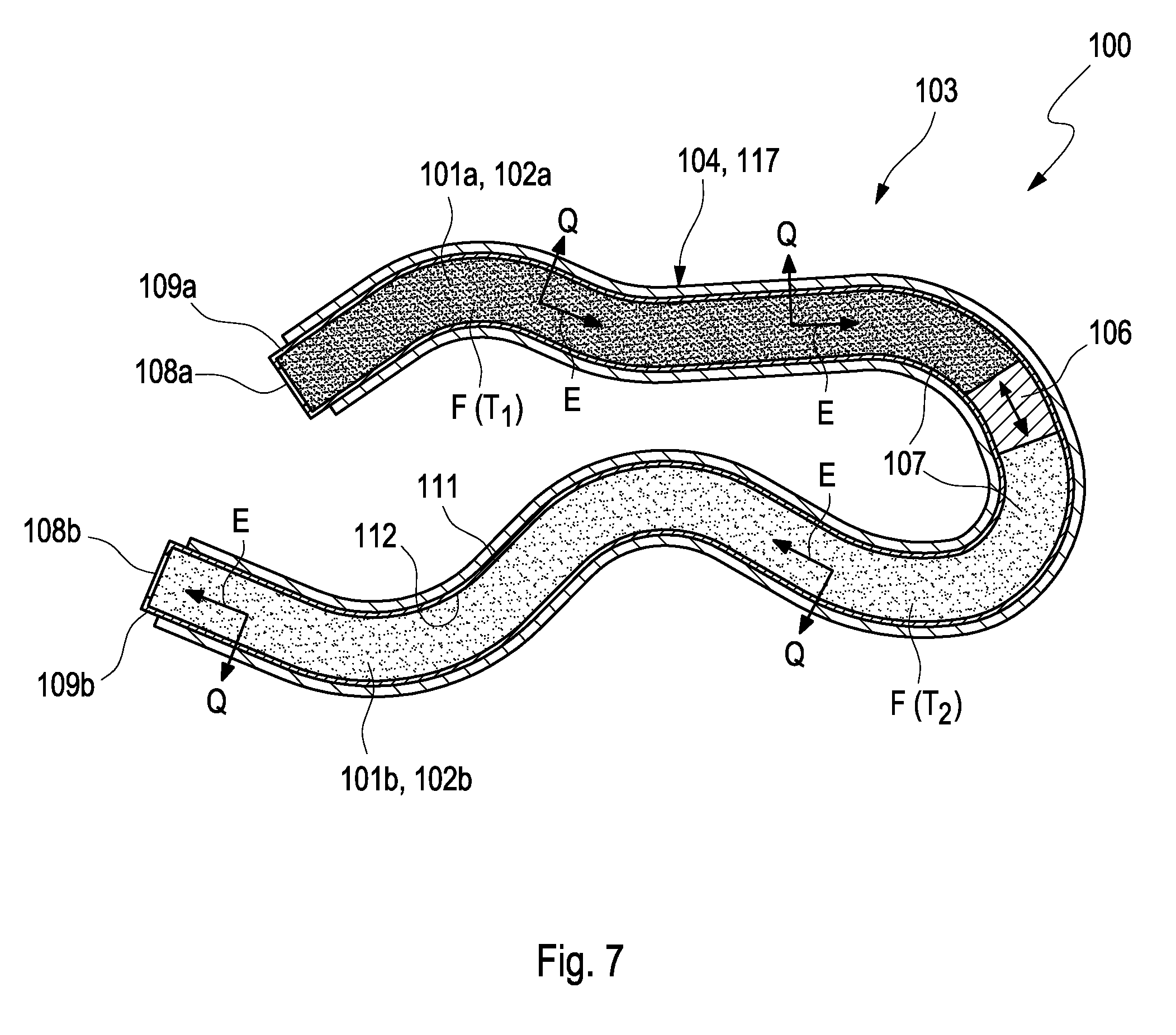
[0070] FIG. 7 shows a further variant of the example in FIG. 5, in which the receptacle 103 is embodied as a hose-like body 117 which extends in an extension direction E, at least sections of which are not non-linear. In this variant, the dividing element 106 lies against the inner side 112 of the circumferential wall 111 of the hose-like body 117 and is movable along it in the extension direction E to form the two volume-variable partial stores 101a, 101b. This variant enables the creation of an arrangement of the receptacle 103 which is particularly compact in terms of space. A length of the housing 104 or the hose-like body 117 measured along the extension direction E is preferably at least ten times, more preferably at least twenty times greater than a transverse direction Q measured transversely to the extension direction E.
* * * * *
D00000
D00001
D00002
D00003
D00004
D00005
D00006
XML
uspto.report is an independent third-party trademark research tool that is not affiliated, endorsed, or sponsored by the United States Patent and Trademark Office (USPTO) or any other governmental organization. The information provided by uspto.report is based on publicly available data at the time of writing and is intended for informational purposes only.
While we strive to provide accurate and up-to-date information, we do not guarantee the accuracy, completeness, reliability, or suitability of the information displayed on this site. The use of this site is at your own risk. Any reliance you place on such information is therefore strictly at your own risk.
All official trademark data, including owner information, should be verified by visiting the official USPTO website at www.uspto.gov. This site is not intended to replace professional legal advice and should not be used as a substitute for consulting with a legal professional who is knowledgeable about trademark law.