Heat Exchange-type Ventilation Device
IIO; Kouji ; et al.
U.S. patent application number 16/325238 was filed with the patent office on 2019-07-04 for heat exchange-type ventilation device. The applicant listed for this patent is Panasonic Intellectual Property Management Co., Ltd.. Invention is credited to Naoyuki FUNADA, Kouji IIO.
| Application Number | 20190203971 16/325238 |
| Document ID | / |
| Family ID | 61690419 |
| Filed Date | 2019-07-04 |


View All Diagrams
| United States Patent Application | 20190203971 |
| Kind Code | A1 |
| IIO; Kouji ; et al. | July 4, 2019 |
HEAT EXCHANGE-TYPE VENTILATION DEVICE
Abstract
Provided is a heat exchange-type ventilation device (1) comprising: an air supply blower including an air supply motor; an exhaust blower including an exhaust motor; an air supply path (7) through which air is sent to a room from outside by the air supply blower: an exhaust path through which air is sent from the room to outside by the exhaust blower: a heat exchange element provided at a position at which the air supply path (7) and the exhaust path intersect, the heat exchange element being configured to exchange heat between room air and outside air at the time of ventilation; and a current detector configured to detect a current flowing through the air supply motor. Using a controller (11), the heat exchange-type ventilation device controls the number of revolutions of the air supply motor. The air supply path is connected to a circulating air path (14) of unitary air conditioning (13), and the controller (11) changes the opening area of an airflow rate adjustment damper (15) provided in the air supply path (7) so that a current value of the air supply motor, the current value being detected by the current detector, falls within a predetermined range of a target current value.
| Inventors: | IIO; Kouji; (Aichi, JP) ; FUNADA; Naoyuki; (Aichi, JP) | ||||||||||
| Applicant: |
|
||||||||||
|---|---|---|---|---|---|---|---|---|---|---|---|
| Family ID: | 61690419 | ||||||||||
| Appl. No.: | 16/325238 | ||||||||||
| Filed: | September 15, 2017 | ||||||||||
| PCT Filed: | September 15, 2017 | ||||||||||
| PCT NO: | PCT/JP2017/033390 | ||||||||||
| 371 Date: | February 13, 2019 |
| Current U.S. Class: | 1/1 |
| Current CPC Class: | F24F 11/74 20180101; F24F 2110/10 20180101; F24F 11/77 20180101; F24F 11/0001 20130101; F24F 13/30 20130101; Y02B 30/70 20130101; F24F 13/10 20130101; F24F 12/006 20130101; Y02B 30/746 20130101; F24F 7/08 20130101 |
| International Class: | F24F 12/00 20060101 F24F012/00; F24F 7/08 20060101 F24F007/08; F24F 13/10 20060101 F24F013/10; F24F 13/30 20060101 F24F013/30; F24F 11/00 20060101 F24F011/00; F24F 11/77 20060101 F24F011/77 |
Foreign Application Data
| Date | Code | Application Number |
|---|---|---|
| Sep 26, 2016 | JP | 2016-186423 |
| Jul 25, 2017 | JP | 2017-143647 |
Claims
1. A heat exchange-type ventilation device, comprising: an air supply blower including an air supply motor; an exhaust blower including an exhaust motor; an air supply path through which air is sent to a room from outside by the air supply blower: an exhaust path through which air is sent from the room to outside by the exhaust blower: a heat exchange element provided at a position at which the air supply path and the exhaust path intersect, the heat exchange element being configured to exchange heat between room air and outside air at a time of ventilation; and a current detector configured to detect a current flowing through the air supply motor, wherein a controller controls the number of revolutions of the air supply motor, wherein the air supply path is connected to a circulating air path of unitary air conditioning, and wherein the controller changes an opening area of an airflow rate adjustment damper provided in the air supply path so that a current value of the air supply motor, the current value being detected by the current detector, falls within a predetermined range of a target current value.
2. The heat exchange-type ventilation device according to claim 1, wherein, while exercising control so that the number of revolutions of the air supply motor is kept at a predetermined number of revolutions, the controller changes the opening area of the airflow rate adjustment damper so that the current value of the air supply motor falls within the predetermined range of the target current value.
3. A heat exchange-type ventilation device, comprising: an air supply blower including an air supply motor; an exhaust blower including an exhaust motor; an air supply path through which air is sent to a room from outside by the air supply blower: an exhaust path through which air is sent from the room to outside by the exhaust blower: a heat exchange element provided at a position at which the air supply path and the exhaust path intersect, the heat exchange element being configured to exchange heat between room air and outside air at a time of ventilation; and a current detector configured to detect a current flowing through the exhaust motor, wherein a controller controls the number of revolutions of the exhaust motor, wherein the exhaust path is connected to a circulating air path of unitary air conditioning, and wherein the controller changes an opening area of an airflow rate adjustment damper provided in the exhaust path so that a current value of the exhaust motor, the current value being detected by the current detector, falls within a predetermined range of a target current value.
4. The heat exchange-type ventilation device according to claim 3, wherein, while exercising control so that the number of revolutions of the exhaust motor is kept at a predetermined number of revolutions, the controller changes the opening area of the airflow rate adjustment damper so that the current value of the exhaust motor falls within the predetermined range of the target current value.
5. A heat exchange-type ventilation device, comprising: an air supply blower including an air supply motor; an exhaust blower including an exhaust motor; an air supply path through which air is sent to a room from outside by the air supply blower: an exhaust path through which air is sent from the room to outside by the exhaust blower: a heat exchange element provided at a position at which the air supply path and the exhaust path intersect, the heat exchange element being configured to exchange heat between room air and outside air at a time of ventilation; and a supply airflow rate adjustment damper provided in the air supply path, wherein a controller controls ON/OFF of the air supply blower, ON/OFF of the exhaust blower, and opening/closing of the supply airflow rate adjustment damper, wherein the air supply path is directly connected to a circulating air path of unitary air conditioning, wherein the exhaust path is directly connected to an indoor space except the circulating air path, wherein a room temperature detector is provided in the exhaust path and upstream from the heat exchange element, and, wherein the controller exercises control so that, when "the unitary air conditioning is ON" and "T.sub.i.ltoreq.T.sub.u-.alpha..sub.1 or T.sub.u+.alpha..sub.2.ltoreq.T.sub.i", "the exhaust blower is OFF" and "the supply airflow rate adjustment damper is closed", and when "the unitary air conditioning is ON" and "T.sub.u-.alpha..sub.1<T.sub.i<T.sub.u+.alpha..sub.2", "the exhaust blower is ON" and "the supply airflow rate adjustment damper is opened", where T.sub.i is a room temperature detected by the room temperature detector, T.sub.u is a set temperature of the unitary air conditioning, and .alpha..sub.1 and .alpha..sub.2 are predetermined temperatures.
6. The heat exchange-type ventilation device according to claim 5, wherein the controller exercises control so that, when "the unitary air conditioning is ON" and "T.sub.i.ltoreq.T.sub.u-.alpha..sub.1 or T.sub.u+.alpha..sub.2.ltoreq.T.sub.i", "the air supply blower is OFF".
7. The heat exchange-type ventilation device according to claim 5, wherein, when the set temperature T.sub.u of the unitary air conditioning is changed, the controller checks again whether "T.sub.u-.alpha..sub.1<T.sub.i<T.sub.u+.alpha..sub.2" is satisfied, wherein, when "the unitary air conditioning is ON" and "T.sub.i.ltoreq.T.sub.u-.alpha..sub.1 or T.sub.u+.alpha..sub.2.ltoreq.T.sub.i", the controller exercises control so that "the exhaust blower is OFF" and "the supply airflow rate adjustment damper is closed", and wherein, when "the unitary air conditioning is ON" and "T.sub.u-.alpha..sub.1<T.sub.i<T.sub.u+.alpha..sub.2", the controller exercises control so that "the exhaust blower is ON" and "the supply airflow rate adjustment damper is opened".
8. A heat exchange-type ventilation device, comprising: an air supply blower including an air supply motor; an exhaust blower including an exhaust motor; an air supply path through which air is sent to a room from outside by the air supply blower: an exhaust path through which air is sent from the room to outside by the exhaust blower: a heat exchange element provided at a position at which the air supply path and the exhaust path intersect, the heat exchange element being configured to exchange heat between room air and outside air at a time of ventilation; a supply airflow rate adjustment damper provided in the air supply path; and an exhaust airflow rate adjustment damper provided in the exhaust path, wherein a controller controls ON/OFF of the air supply blower, ON/OFF of the exhaust blower, opening/closing of the supply airflow rate adjustment damper, and opening/closing of the exhaust airflow rate adjustment damper, wherein the air supply path is directly connected to a circulating air path of unitary air conditioning, wherein the exhaust path is directly connected to the circulating air path, wherein a room temperature detector is provided in the exhaust path and upstream from the heat exchange element, and wherein the controller exercises control so that, when "the unitary air conditioning is ON" and "T.sub.i.ltoreq.T.sub.u-.alpha..sub.1 or T.sub.u+.alpha..sub.2.ltoreq.T.sub.i", "the supply airflow rate adjustment damper is closed" and "the exhaust airflow rate adjustment damper is closed", and when "the unitary air conditioning is ON" and "T.sub.u-.alpha..sub.1<T.sub.i<T.sub.u+.alpha..sub.2", "the air supply blower is ON", "the exhaust blower is ON", "the supply airflow rate adjustment damper is opened", and "the exhaust airflow rate adjustment damper is opened", where T.sub.i is a room temperature detected by the room temperature detector, T.sub.u is a set temperature of the unitary air conditioning, and .alpha..sub.1 and .alpha..sub.2 are predetermined temperatures.
9. The heat exchange-type ventilation device according to claim 8, wherein, when "the unitary air conditioning is ON" and "T.sub.i.ltoreq.T.sub.u-.alpha..sub.1 or T.sub.u+.alpha..sub.2.ltoreq.T.sub.i", the controller exercises control so that "the air supply blower and the exhaust blower are OFF".
10. The heat exchange-type ventilation device according to claim 8, wherein, when "the unitary air conditioning is ON" and "T.sub.i.ltoreq.T.sub.u -.alpha..sub.1 or T.sub.u+.alpha..sub.2.ltoreq.T.sub.i", the controller exercises control so that "the air supply blower or the exhaust blower is OFF".
11. The heat exchange-type ventilation device according to claim 8, wherein, when the set temperature T.sub.u of the unitary air conditioning is changed, the controller checks again whether "T.sub.u-.alpha..sub.1<T.sub.i<T.sub.u+.alpha..sub.2" is satisfied, and wherein, when "the unitary air conditioning is ON" and "T.sub.i.ltoreq.T.sub.u -.alpha..sub.1 or T.sub.u+.alpha..sub.2.ltoreq.T.sub.i", the controller exercises control so that "the supply airflow rate adjustment damper is closed" and "the exhaust airflow rate adjustment damper is closed", and wherein, when "the unitary air conditioning is ON" and "T.sub.u-.alpha..sub.1<T.sub.i<T.sub.u+.alpha..sub.2", the controller exercises control so that "the air supply blower is ON", "the exhaust blower is ON", "the supply airflow rate adjustment damper is opened", and "the exhaust airflow rate adjustment damper is opened".
12. The heat exchange-type ventilation device according to claim 8, the device further comprising a casing configured to accommodate the air supply blower, the exhaust blower, and the heat exchange element, wherein the supply airflow rate adjustment damper is provided inside the casing.
Description
TECHNICAL FIELD
[0001] The present disclosure relates to a heat exchange-type ventilation device.
BACKGROUND ART
[0002] As a conventional ventilation device configured to exchange heat between outside air and room air, there is known a heat exchange-type ventilation device that is installed in a building and configured to introduce outside air from an outside-air inlet port and supply the air to a room via a built-in heat exchange element (for example, refer to Patent Literature 1).
[0003] Hereinafter, this heat exchange-type ventilation device will be described with reference to FIG. 11.
[0004] FIG. 11 is a configuration diagram illustrating a top view of the conventional heat exchange-type ventilation device.
[0005] As illustrated in FIG. 11, ventilation device body 201 is installed in an attic space or a ceiling space inside a building.
[0006] Fresh outside air is introduced from outside-air inlet port 202, flows through built-in heat exchange element 203, and is supplied to a room via indoor air-supply port 204.
[0007] On the other hand, contaminated room air is introduced from indoor exhaust port 205, flows through heat exchange element 203, and is discharged to outside via outdoor exhaust port 206.
[0008] It is configured such that fresh outside air introduced from outside-air inlet port 202 and contaminated room air introduced from indoor exhaust port 205 are transported via heat exchange element 203 by air supply blower 209 and exhaust blower 210, respectively, that are connected to motor 207 by same shaft 208.
CITATION LIST
[0009] Patent Literature 1: Japanese Unexamined Patent Application Publication No. 11-325535
SUMMARY OF INVENTION
[0010] In heat exchange-type ventilation devices, the airflow rate of an air supply path or an exhaust path needs to be adjusted for ventilation.
[0011] In the case where an air supply path (or an exhaust path) of a conventional heat exchange-type ventilation device is connected to a circulating air path of unitary air conditioning, an airflow rate adjustment damper is installed inside a duct in the air supply path (or the exhaust path) of the heat exchange-type ventilation device in order to adjust an airflow rate. However, this configuration has a problem that it is required to determine the angle (the opening area) of the airflow rate adjustment damper while measuring an airflow rate, and this makes on-site installation complicated.
[0012] The present disclosure solves the above-mentioned conventional problem, and an object of the present disclosure is to provide a heat exchange-type ventilation device capable of automatically determining the opening area of an airflow rate adjustment damper and thereby simplifying on-site installation. Note that simplified installation is merely an example, and a configuration having a feature except simplified installation is not limited to the heat exchange-type ventilation device capable of simplifying installation.
[0013] To achieve this object, a heat exchange-type ventilation device according to one aspect of the present disclosure comprises: an air supply blower including an air supply motor; an exhaust blower including an exhaust motor; an air supply path through which air is sent to a room from outside by the air supply blower: an exhaust path through which air is sent from the room to outside by the exhaust blower: a heat exchange element provided at a position at which the air supply path and the exhaust path intersect, the heat exchange element being configured to exchange heat between room air and outside air at the time of ventilation; and a current detector configured to detect a current flowing through the air supply motor. The heat exchange-type ventilation device is configured such that a controller controls the number of revolutions of the air supply motor, and the air supply path is connected to a circulating air path of unitary air conditioning. The controller changes the opening area of an airflow rate adjustment damper provided in the air supply path so that a current value of the air supply motor, the current value being detected by the current detector, falls within a predetermined range of a target current value. Thus, the desired object is attained.
[0014] The present disclosure can provide a heat exchange-type ventilation device capable of simplifying on-site installation. Note that simplified installation is merely an example, and a configuration having a feature except simplified installation is not limited to the heat exchange-type ventilation device capable of simplifying installation. For example, a heat exchange-type ventilation device capable of enhancing the temperature adjustment efficiency of unitary air conditioning when connected to the unitary air conditioning can be provided regardless of simplified installation.
BRIEF DESCRIPTION OF DRAWINGS
[0015] FIG. 1 is a top cross-sectional view of a heat exchange-type ventilation device of Embodiment 1 according to the present disclosure.
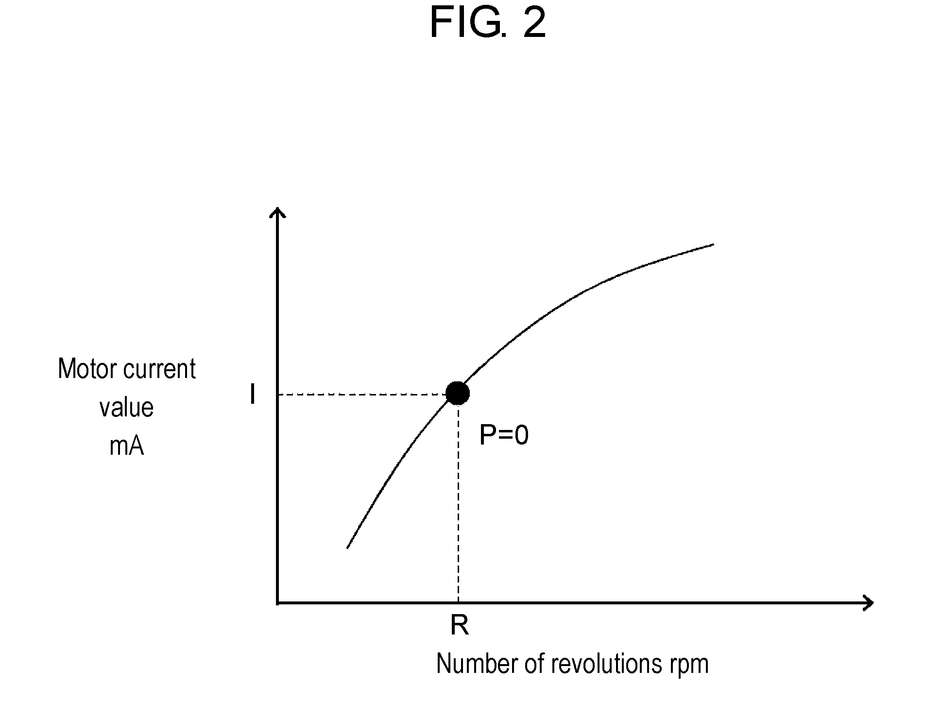
[0016] FIG. 2 is a graph illustrating the relation between the number of revolutions of a motor of the heat exchange-type ventilation device of Embodiment 1 and a current value of the motor.
[0017] FIG. 3 is a diagram illustrating an installation example of the heat exchange-type ventilation device of Embodiment 1.
[0018] FIG. 4 is a diagram illustrating another installation example of the heat exchange-type ventilation device of Embodiment 1.
[0019] FIG. 5 is a top cross-sectional view of a heat exchange-type ventilation device of Embodiment 2.
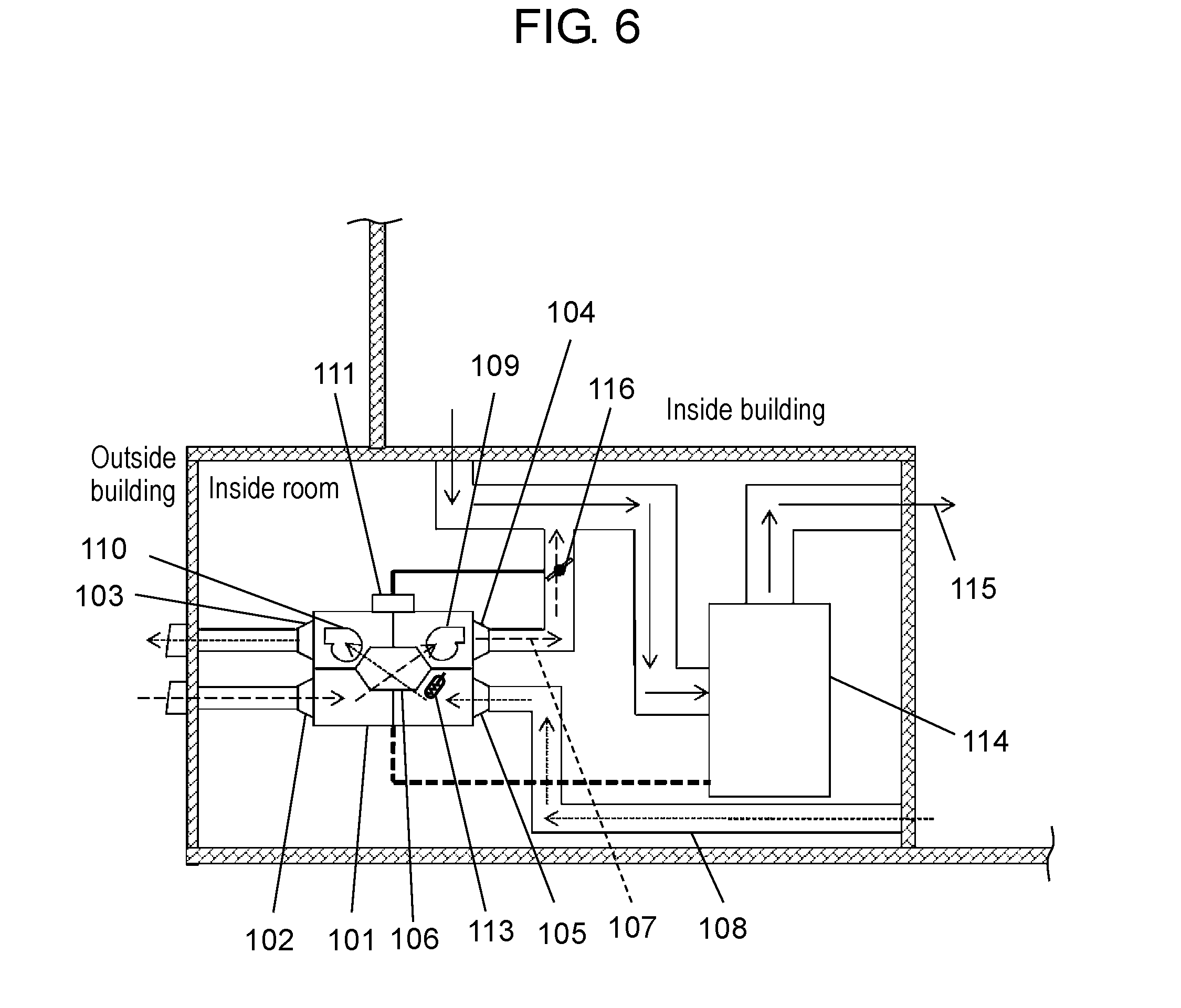
[0020] FIG. 6 is a diagram illustrating an installation example of the heat exchange-type ventilation device of Embodiment 2.
[0021] FIG. 7 is a control block diagram of the heat exchange-type ventilation device of Embodiment 2.
[0022] FIG. 8 is a diagram illustrating another installation example of the heat exchange-type ventilation device of Embodiment 2.
[0023] FIG. 9 is a control block diagram of the heat exchange-type ventilation device illustrated in FIG. 8.
[0024] FIG. 10 is a diagram illustrating another installation example of the heat exchange-type ventilation device of Embodiment 2.
[0025] FIG. 11 is a top cross-sectional view of a conventional heat exchange-type ventilation device.
DESCRIPTION OF EMBODIMENTS
[0026] A heat exchange-type ventilation device according to one aspect of the present disclosure comprises: an air supply blower including an air supply motor; an exhaust blower including an exhaust motor; an air supply path through which air is sent to a room from outside by the air supply blower: an exhaust path through which air is sent from the room to outside by the exhaust blower: a heat exchange element provided at a position at which the air supply path and the exhaust path intersect, the heat exchange element being configured to exchange heat between room air and outside air at the time of ventilation; and a current detector configured to detect a current flowing through the air supply motor. The heat exchange-type ventilation device is configured such that a controller controls the number of revolutions of the air supply motor, and the air supply path is connected to a circulating air path of unitary air conditioning. The controller changes the opening area of an airflow rate adjustment damper provided in the air supply path so that a current value of the air supply motor, the current value being detected by the current detector, falls within a predetermined range of a target current value.
[0027] This enables automatic determination of the opening area of the airflow rate adjustment damper, simplification of on-site installation, and a reduction in man-hours. Furthermore, in the case where a driving notch is changed after the completion of installation, the airflow rate adjustment damper can be automatically adjusted without being adjusted and installed again, whereby man-hours can be reduced. Note that the same effect is achieved also in the case where the exhaust path is connected to the circulating air path of unitary air conditioning and the opening area of the airflow rate adjustment damper provided in the exhaust path is changed.
[0028] Hereinafter, embodiments of the present disclosure will be described with reference to the drawings.
Embodiment 1
[0029] An interior configuration, an air supply path, and an exhaust path of a heat exchange-type ventilation device of Embodiment 1 will be described using FIG. 1.
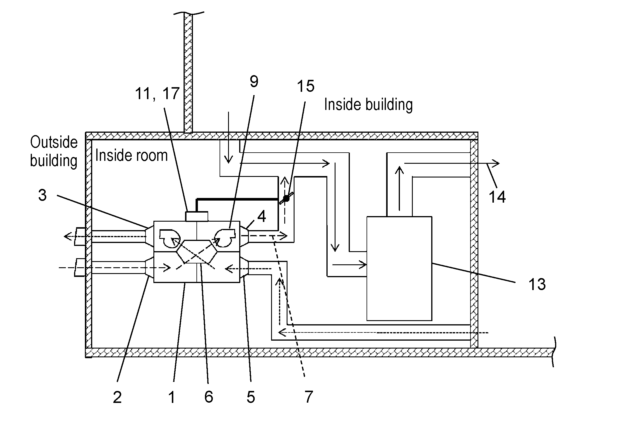
[0030] FIG. 1 is a top cross-sectional view of the heat exchange-type ventilation device of Embodiment 1.
[0031] As illustrated in FIG. 1, heat exchange-type ventilation device 1 includes: outside-air inlet port 2 and room-air exhaust port 3 which are provided in one side face of a box-shaped body of heat exchange-type ventilation device 1; and outside-air supply port 4 and room-air inlet port 5 which are provided in another side face opposed to the one side face.
[0032] Heat exchange-type ventilation device 1 further includes air supply path 7 into which fresh outside air (supply air) is drawn from outside-air inlet port 2 provided in the side face of the body and through which the air is supplied to a room from outside-air supply port 4 via heat exchange element 6 provided inside heat exchange-type ventilation device 1.
[0033] Heat exchange-type ventilation device 1 further includes exhaust path 8 into which contaminated room air (exhaust air) is drawn from room-air inlet port 5 and through which the air is exhausted from room-air exhaust port 3 to outside via heat exchange element 6. Here, heat exchange element 6 has a heat recovery function of supplying the amount of heat of exhaust air to supply air or supplying the amount of heat of supply air to exhaust air.
[0034] Fresh outside air (supply air) introduced from outside-air inlet port 2 flows through air supply path 7 by operating air supply blower 9. Contaminated room air (exhaust air) introduced from room-air inlet port 5 flows through exhaust path 8 by operating exhaust blower 10.
[0035] Heat exchange element 6 is provided at a position at which air supply path 7 and exhaust path 8 intersect. Air purifying filter 12 is provided on each of the outside air inlet side and the room air inlet side of heat exchange element 6. Outside-air inlet port 2, room-air exhaust port 3, outside-air supply port 4, and room-air inlet port 5 each have a form capable of being connected to a duct.
[0036] Furthermore, heat exchange-type ventilation device 1 includes controller 11 configured to control the number of revolutions of the air supply motor of air supply blower 9 and the number of revolutions of the exhaust motor of exhaust blower 10. Controller 11 controls the number of revolutions of the air supply motor of air supply blower 9 and the number of revolutions of the exhaust motor of exhaust blower 10 so as to keep constant the airflow rate of supply air and the airflow rate of exhaust air, and includes current detector 17 configured to detect a current flowing through the air supply motor or the exhaust motor.
[0037] Here, the control exercised by controller 11 to keep the airflow rate of supply air and the airflow rate of exhaust air constant will be described. When heat exchange-type ventilation device 1 is activated, controller 11 controls the number of revolutions of the air supply motor of air supply blower 9 and the number of revolutions of the exhaust motor of exhaust blower 10 so that the amount of air sent by air supply blower 9 is equal to the amount of air sent by exhaust blower 10 (heat exchange operation). When a heat exchange-type ventilation device starts to operate in an installed state, a certain external static pressure due to an installed duct is usually put on the heat exchange-type ventilation device. Therefore, in order to output a predetermined airflow rate, while checking the number of revolutions of the air supply motor and the number of revolutions of the exhaust motor, controller 11 controls a current value of each of the motors. To output the predetermined airflow rate, controller 11 stores in advance the relation between the number of revolutions of the air supply motor and a current value of the air supply motor and the relation between the number of revolutions of the exhaust motor and a current value of the exhaust motor.
[0038] FIG. 2 is a graph illustrating the relation between the number of revolutions of a motor of the heat exchange-type ventilation device of Embodiment 1 and a current value of the motor. Controller 11 matches a predetermined airflow rate with this relation between the number of revolutions of a motor and a current value of the motor. In other words, on the line shown in FIG. 2, an airflow rate is controlled to be constant.
[0039] Here, a characteristic aspect of the present embodiment, that is, the operation of an airflow rate adjustment damper by controller 11 will be described.
[0040] FIG. 3 is a diagram illustrating an installation example of the heat exchange-type ventilation device of Embodiment 1.
[0041] Unitary air conditioning 13 is installed in a machine room or other spaces inside a building, and connected to a room by a duct to form circulating air path 14 in the room.
[0042] Unitary air conditioning 13 heats or cools a room so as to attain a predetermined room temperature, sends air to circulating air path 14, and circulates the air in a plurality of rooms in a building to adjust indoor temperatures to a predetermined temperature.
[0043] Circulating air path 14 is a temperature adjustment path via unitary air conditioning 13, in which the ventilation of a building is not performed, and accordingly fresh air is not supplied to the building from outside. Then, by connecting circulating air path 14 to air supply path 7, temperatures are adjusted by indoor circulation, and at the same time, heat exchange is performed to draw fresh outside air into the building while performing heat recovery. Here, air supply path 7 provided downstream from heat exchange element 6 is connected to circulating air path 14 of unitary air conditioning 13.
[0044] At this time, while unitary air conditioning 13 performs an indoor circulating operation, a negative pressure is put on outside-air supply port 4 of heat exchange-type ventilation device 1 due to an air-blowing function of unitary air conditioning 13. Thus, air flows through air supply path 7 of heat exchange-type ventilation device 1 at an airflow rate higher than designed, since the air is drawn into air supply path 7 by unitary air conditioning 13. Therefore, particularly in winter, there is a possibility that a large amount of outside air having a lower temperature flows in and thereby causes troubles such as dew condensation. To prevent such troubles, airflow rate adjustment damper 15 configured to offset a negative pressure from unitary air conditioning 13 is provided in air supply path 7 between heat exchange-type ventilation device 1 and circulating air path 14 of unitary air conditioning 13.
[0045] Conventionally, the angle of airflow rate adjustment damper 15 has been determined in such a manner that, while the airflow rate of supply air of heat exchange-type ventilation device 1 is actually measured, the opening area (opening ratio) of the damper is adjusted so as to attain a predetermined airflow rate. However, this makes on-site installation complicated because, for example, an airflow rate needs to be measured each time.
[0046] In the present embodiment, the opening area (opening ratio) of airflow rate adjustment damper 15 is automatically adjusted by controller 11, and thus, man-hours on site can be reduced.
[0047] Specifically, controller 11 operates air supply blower 9 at a predetermined constant number of revolutions. At this time, if unitary air conditioning 13 is operated and airflow rate adjustment damper 15 is fully opened, a negative pressure causes a load put on air supply blower 9 to be reduced, and the air supply motor has a current value, detected by current detector 17, smaller than a predetermined current value.
[0048] Then, controller 11 changes the angle of airflow rate adjustment damper 15 by a predetermined degree (for example, by 1.degree.) each time so as to make smaller the damper opening area (opening ratio) of airflow rate adjustment damper 15. When a current value falls within a predetermined range (for example, within a margin of 1% or less) of a target current value, controller 11 terminates the adjustment of airflow rate adjustment damper 15 and determines the angle of airflow rate adjustment damper 15.
[0049] Here, the number of revolutions of air supply blower 9 at the time of the adjustment of airflow rate adjustment damper 15 is preferably the number of revolutions at the time when an external static pressure is 0 Pa (P=0 in FIG. 2), at which power consumption is reduced to a minimum. This is because, at the time when an external static pressure is 0 Pa (P=0 in FIG. 2), pressure loss can be reduced to a minimum.
[0050] Furthermore, when controller 11 operates air supply blower 9 at a predetermined constant number of revolutions, if unitary air conditioning 13 is operated and airflow rate adjustment damper 15 is fully closed, air supply blower 9 has no air-blowing path and accordingly cannot work. Therefore, the air supply motor has a current value, detected by current detector 17, smaller than a predetermined current value. Then, controller 11 changes the angle of airflow rate adjustment damper 15 by a predetermined degree (for example, by 1.degree.) each time so as to make larger the damper opening area (opening ratio) of airflow rate adjustment damper 15. When a current value falls within a predetermined range (for example, within a margin of 1% or less) of a target current value, controller 11 terminates the adjustment of airflow rate adjustment damper 15 and determines the angle of airflow rate adjustment damper 15.
[0051] Heat exchange-type ventilation device 1 of the present embodiment operates so as to keep the number of revolutions of a motor constant, adjusts the damper opening area (opening ratio) of airflow rate adjustment damper 15 so that a current value of the motor falls within a predetermined range of a target current value, and determines the angle of airflow rate adjustment damper 15. Alternatively, heat exchange-type ventilation device 1 may operate so as to keep a current value of a motor constant, may adjust the damper opening area (opening ratio) of airflow rate adjustment damper 15 so that the number of revolutions of the motor falls within a predetermined range of a target number of revolutions, and thus may determine the angle of airflow rate adjustment damper 15. In this case, a number-of-revolutions detector (not illustrated) is provided in place of current detector 17, and this number-of-revolutions detector detects the number of revolutions of the air supply motor or the exhaust motor, and controller 11 determines the angle of airflow rate adjustment damper 15.
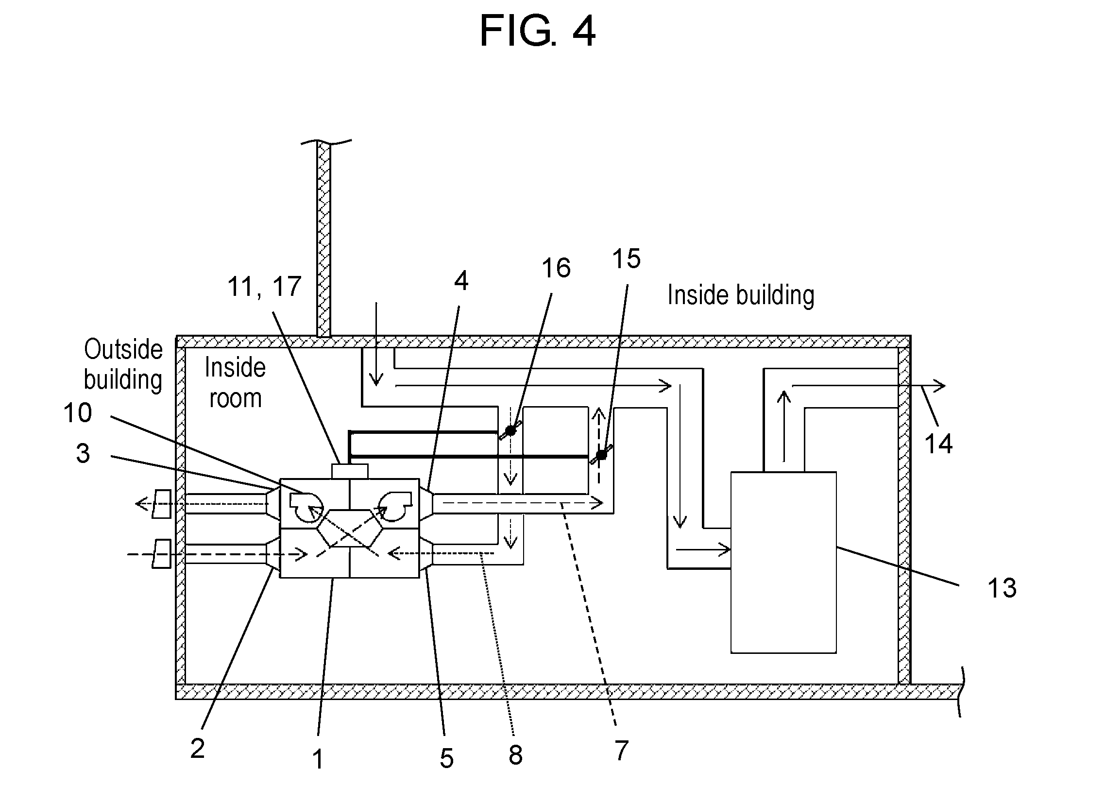
[0052] FIG. 4 is a diagram illustrating another installation example of the heat exchange-type ventilation device of Embodiment 1. As illustrated in FIG. 4 showing the installation example, indoor circulating air path 14 may be connected to exhaust path 8. While unitary air conditioning 13 performs an indoor circulating operation, a negative pressure is put on room-air inlet port 5 of heat exchange-type ventilation device 1 due to the air-blowing function of unitary air conditioning 13. Thus, air is drawn by unitary air conditioning 13, and accordingly air is not allowed to flow through exhaust path 8 of heat exchange-type ventilation device 1 at a designed airflow rate. Therefore, particularly in winter, room air having a temperature higher than the temperature of outside air is less likely to flow, and outside air not subjected to heat exchange flows directly into a room via air supply path 7, and accordingly, there is a possibility of causing troubles such as dew condensation and a feeling of cold air. To prevent such troubles, airflow rate adjustment damper 16 configured to offset a negative pressure from unitary air conditioning 13 is provided in exhaust path 8 between heat exchange-type ventilation device 1 and circulating air path 14 of unitary air conditioning 13.
[0053] The opening area (opening ratio) of airflow rate adjustment damper 16 is automatically adjusted by controller 11, and thus, man-hours on site can be reduced.
[0054] Specifically, controller 11 operates exhaust blower 10 at a predetermined constant number of revolutions. At this time, if unitary air conditioning 13 is operated and airflow rate adjustment damper 16 is fully opened, a larger load is put on exhaust blower 10 due to a negative pressure, and accordingly exhaust blower 10 cannot send air. Exhaust blower 10 thus does not work, and accordingly the exhaust motor has a current value, detected by current detector 17, smaller than a predetermined current value. Then, controller 11 changes the angle of airflow rate adjustment damper 16 by a predetermined degree (for example, by 1.degree.) each time so as to make smaller the damper opening area (opening ratio) of airflow rate adjustment damper 16. When a current value falls within a predetermined range (for example, within a margin of 1% or less) of a target current value, controller 11 terminates the adjustment of airflow rate adjustment damper 16 and determines the angle of airflow rate adjustment damper 16.
[0055] Here, the number of revolutions of exhaust blower 10 at the time of the adjustment of airflow rate adjustment damper 16 is preferably the number of revolutions at the time when an external static pressure is 0 Pa (P=0 in FIG. 2), at which power consumption is reduced to a minimum.
[0056] Furthermore, when controller 11 operates exhaust blower 10 at a predetermined constant number of revolutions, if unitary air conditioning 13 is operated and airflow rate adjustment damper 16 is fully closed, exhaust blower 10 has no air-blowing path and accordingly cannot work. Therefore, the exhaust motor has a current value, detected by current detector 17, smaller than a predetermined current value. Then, controller 11 changes the angle of airflow rate adjustment damper 16 by a predetermined degree (for example, by 1.degree.) each time so as to make larger the opening area (opening ratio) of airflow rate adjustment damper 16. When a current value falls within a predetermined range (for example, within a margin of 1% or less) of a target current value, controller 11 terminates the adjustment of airflow rate adjustment damper 16 and determines the angle of airflow rate adjustment damper 16.
[0057] Thus, there can be attained heat exchange-type ventilation device 1 capable of simplifying on-site installation and reducing man-hours by automatically determining the angle of airflow rate adjustment damper 16.
[0058] Hereinafter, the present embodiment will be additionally described.
[0059] Unitary air conditioning 13 includes a concept of whole building air conditioning or central air conditioning.
[0060] In the embodiment above, controller 11 is provided in heat exchange-type ventilation device 1, but may not be provided in heat exchange-type ventilation device 1. In this case, control is exercised by controller 11 located at some distance from heat exchange-type ventilation device 1.
[0061] In the embodiment above, controller 11 includes current detector 17, but, current detector 17 may be provided so as to be separated from controller 11.
[0062] In the embodiment above, controller 11 detects and controls the number of revolutions and a current value of each of the air supply motor and the exhaust motor so that the supply airflow rate and the exhaust airflow rate are controlled to be constant. This control is exercised in order to determine the position of P=0 in FIG. 2. The position of P=0 in FIG. 2 is not necessarily determined, and hence, airflow rate control for keeping the supply airflow rate and the exhaust airflow rate constant is not absolutely required. In the case where the airflow rate control is not performed, sometimes the position of P=0 cannot be determined, but a target current value may be set to be within a range of P>0 (positive pressure) at the right of the point P=0 in FIG. 2 or a range of P<0 (negative pressure) at the left of the point P=0. Alternatively, a target current value may be set as any constant. In this case, controller 11 may change the opening area of the airflow rate adjustment damper provided in air supply path 7 (or exhaust path 8) so that a current value, detected by current detector 17, of the air supply motor (or the exhaust motor) falls within a predetermined range of a target current value. Furthermore, in this case, while controlling the number of revolutions of the air supply motor (or the exhaust motor) to be kept at a predetermined number of revolutions, controller 11 may change the opening area of an airflow rate adjustment damper provided in air supply path 7 (or exhaust path 8) so that a current value of the air supply motor (or the exhaust motor) falls within a predetermined range of a target current value.
[0063] In the case of not exercising the airflow rate control, the number of revolutions of each of the air supply motor and the exhaust motor is not necessarily detected. In this case, controller 11 detects a current value of the air supply motor (or the exhaust motor) and an opening area of an airflow rate adjustment damper (or the angle of an airflow rate adjustment damper).
[0064] In the case where the airflow rate control is not performed and a number-of-revolutions detector (not illustrated) is provided, a current value of each of the air supply motor and the exhaust motor is not necessarily detected. In this case, controller 11 detects the number of revolutions of the air supply motor (or the exhaust motor) and the opening area of an airflow rate adjustment damper (or the angle of the airflow rate adjustment damper). Furthermore, for example, controller 11 may operate so as to make the current value of the air supply motor (or exhaust motor) constant, and may adjust the damper opening area (opening ratio) of airflow rate adjustment damper 15 and determine the angle of airflow rate adjustment damper 15 so that the number of revolutions of the air supply motor (or the exhaust motor) falls within a predetermined range of a target number of revolutions.
[0065] Controller 11 may operate airflow rate adjustment damper 15 provided in air supply path 7 or airflow rate adjustment damper 16 provided in exhaust path 8 so that a current value of the air supply motor (or the exhaust motor) is a current value of the air supply motor (or the exhaust motor) configured to output a predetermined airflow rate at a predetermined external static pressure.
Embodiment 2
[0066] Next, a heat exchange-type ventilation device of Embodiment 2 will be described.
[0067] In the case where an air supply path (or an exhaust path) of a conventional heat exchange-type ventilation device is connected to a circulating air path of unitary air conditioning, the unitary air conditioning communicates with outside air via the heat exchange-type ventilation device, and therefore, when outside air is introduced at the time of operation of unitary air conditioning, the temperature adjustment efficiency of the unitary air conditioning is sometimes lower than that in a case in which indoor circulation is performed without introducing outside air.
[0068] Hence, an object of Embodiment 2 is to achieve a heat exchange-type ventilation device capable of, when a room temperature is not within a predetermined range of a set temperature of unitary air conditioning, enhancing the temperature adjustment efficiency of the unitary air conditioning by preventing outside air from being introduced.
[0069] To achieve this object, the heat exchange-type ventilation device of Embodiment 2 comprises: an air supply blower including an air supply motor; an exhaust blower including an exhaust motor; an air supply path through which air is sent to a room from outside by the air supply blower: an exhaust path through which air is sent from the room to outside by the exhaust blower: a heat exchange element provided at a position at which the air supply path and the exhaust path intersect, the heat exchange element being configured to exchange heat between room air and outside air at the time of ventilation; and a supply airflow rate adjustment damper provided in the air supply path. Using a controller, the heat exchange-type ventilation device controls ON/OFF of the air supply blower, ON/OFF of the exhaust blower, and opening/closing of the supply airflow rate adjustment damper. The air supply path is directly connected to a circulating air path of unitary air conditioning. The exhaust path is directly connected to an indoor space except the circulating air path. The heat exchange-type ventilation device includes a room temperature detector provided in the exhaust path and upstream from the heat exchange element. The controller exercises control so that, when "the unitary air conditioning is ON" and "T.sub.i.ltoreq.T.sub.u-60 .sub.1 or T.sub.u+.alpha..sub.2.ltoreq.T.sub.i", "the exhaust blower is OFF" and "the supply airflow rate adjustment damper is closed", where T.sub.i a room temperature detected by the room temperature detector, T.sub.u is a set temperature of the unitary air conditioning, and .alpha..sub.1 and .alpha..sub.2 are predetermined temperatures. The controller exercises control so that, when "the unitary air conditioning is ON" and "T.sub.u-.alpha..sub.1<T.sub.i<T.sub.u+.alpha..sub.2", "the exhaust blower is ON" and "the supply airflow rate adjustment damper is opened". Thus, the desired object is achieved.
[0070] The heat exchange-type ventilation device of Embodiment 2 is capable of, when a room temperature is not within a predetermined range of the set temperature of the unitary air conditioning, enhancing the temperature adjustment efficiency of the unitary air conditioning by preventing outside air from being introduced.
[0071] Furthermore, the heat exchange-type ventilation device is capable of, by preventing outside air from being introduced during operation of the unitary air conditioning, reducing a load on the unitary air conditioning to reduce power consumption of the unitary air conditioning and quickly air-conditioning an indoor environment to quickly make the environment comfortable.
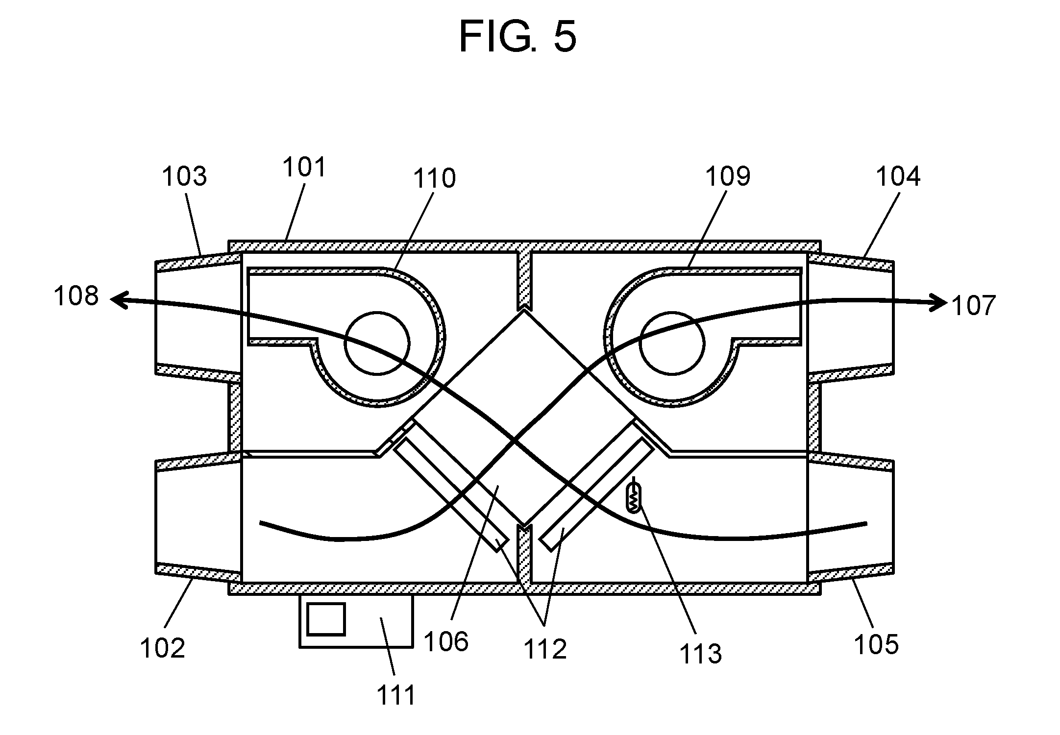
[0072] An interior configuration, the air supply path, and the exhaust path of the heat exchange-type ventilation device of Embodiment 2 will be described using FIG. 5.
[0073] FIG. 5 is a top cross-sectional view of the heat exchange-type ventilation device of Embodiment 2. As illustrated in FIG. 5, heat exchange-type ventilation device 101 includes: outside-air inlet port 102 and room-air exhaust port 103 which are provided in one side face of a box-shaped body of heat exchange-type ventilation device 101; and outside-air supply port 104 and room-air inlet port 105 which are provided in another side face opposed to the one side face.
[0074] Heat exchange-type ventilation device 101 further includes air supply path 107 through which fresh outside air (supply air) is taken in from outside-air inlet port 102 provided in the one side face and is supplied to a room from outside-air supply port 104 via heat exchange element 106 provided inside heat exchange-type ventilation device 101.
[0075] Heat exchange-type ventilation device 101 further includes exhaust path 108 into which contaminated room air (exhaust air) is drawn from room-air inlet port 105 and through which the air is exhausted from room-air exhaust port 103 to outside via heat exchange element 106. Here, heat exchange element 106 has a heat recovery function of supplying the amount of heat of exhaust air to supply air, or supplying the amount of heat of supply air to exhaust air.
[0076] Fresh outside air (supply air) introduced from outside-air inlet port 102 flows through air supply path 107 by operating air supply blower 109. Contaminated room air (exhaust air) introduced from room-air inlet port 105 flows through exhaust path 108 by operating exhaust blower 110.
[0077] Heat exchange element 106 is provided at a position at which air supply path 107 and exhaust path 108 intersect. Air purifying filter 112 is provided on each of the outside-air inlet side and the room-air inlet side of heat exchange element 106. Outside-air inlet port 102, room-air exhaust port 103, outside-air supply port 104, and room-air inlet port 105 each have a form capable of being connected to a duct.
[0078] Room temperature detector 113 configured to detect room temperatures is provided in exhaust path 108 and upstream from heat exchange element 106.
[0079] Here, a characteristic aspect of the present embodiment, that is, the operation of an airflow rate adjustment damper by controller 111 and the operation of the product will be described.
[0080] FIG. 6 is a diagram illustrating an installation example of the heat exchange-type ventilation device of Embodiment 2. Unitary air conditioning 114 is installed in a machine room or other spaces inside a building and connected to a room by a duct to form circulating air path 115 in the room.
[0081] Unitary air conditioning 114 heats or cools a room so as to attain a predetermined room temperature, sends air to circulating air path 115, and circulates the air in a plurality of rooms in a building to adjust indoor temperatures to a predetermined temperature.
[0082] An usual circulating air path is a temperature adjustment path via unitary air conditioning 114, in which the ventilation of a building is not performed, and accordingly fresh air is not supplied to the building from outside. Then, by connecting circulating air path 115 to air supply path 107, temperatures are adjusted by indoor circulation, and at the same time, heat exchange is performed to draw fresh outside air into the building while performing heat recovery. Here, air supply path 107 provided downstream from heat exchange element 106 is connected to circulating air path 115 of unitary air conditioning 114.
[0083] At this time, while unitary air conditioning 114 performs an indoor circulating operation, a negative pressure is put on outside-air supply port 104 of heat exchange-type ventilation device 101 due to an air-blowing function of unitary air conditioning 114. Thus, air flows through air supply path 107 of heat exchange-type ventilation device 101 at an airflow rate higher than designed, since the air is drawn into air supply path 107 by unitary air conditioning 114. Therefore, particularly in winter, there is a possibility that a large amount of outside air having a lower temperature flows in and thereby causes troubles such as dew condensation. To prevent such troubles, airflow rate adjustment damper 116 configured to offset a negative pressure from unitary air conditioning 114 is provided in air supply path 107 between heat exchange-type ventilation device 101 and circulating air path 115 of unitary air conditioning 114. While the airflow rate of supply air of heat exchange-type ventilation device 101 is actually measured, the angle of airflow rate adjustment damper 116 is determined by adjusting the opening area (opening ratio) of airflow rate adjustment damper 116 so as to attain a predetermined airflow rate.
[0084] Ventilation can be performed in such a manner that a temperatures is adjusted by indoor circulation by using unitary air conditioning 114, and at the same time, heat exchange-type ventilation device 101 performs heat exchange, and thus, while performing heat recovery, fresh outside air is drawn into the building.
[0085] On the other hand, particularly at the time of activation of unitary air conditioning 114, for example, outside air having subjected to heat exchange is introduced into circulating air path 115 at the time of heating in winter when a room temperature is adjusted to a set temperature, for example, and this makes an air-conditioning load larger than that in a circulating operation, and accordingly, the length of time that a room temperature reaches a set temperature is longer.
[0086] This happens also in cooling in summer. In other words, when outside air having subjected to heat exchange is introduced at the time of cooling in summer, an air-conditioning load is made larger than that in a circulating operation, and accordingly, the length of time that a room temperature reaches a set temperature is longer.
[0087] FIG. 7 is a control block diagram of the heat exchange-type ventilation device of Embodiment 2.
[0088] In the present embodiment, as illustrated in FIG. 7, controller 111 controls air supply blower 109, exhaust blower 110, and supply airflow rate adjustment damper 116. By preventing outside air from being introduced during the operation of unitary air conditioning 114, a load on unitary air conditioning 114 can be reduced to achieve a reduction in the power consumption of unitary air conditioning 114 and an indoor environment can be quickly air-conditioned to quickly make the environment comfortable.
[0089] Controller 111 exercises control by comparing a room temperature obtained from room temperature detector 113 with a set temperature of unitary air conditioning 114.
[0090] Control operations illustrated in FIG. 7 will be specifically described. In FIG. 7, T.sub.i is a room temperature detected by room temperature detector 113, T.sub.u is a set temperature of unitary air conditioning 114, and .alpha..sub.1 and .alpha..sub.2 are predetermined temperatures.
[0091] During the halting of unitary air conditioning 114, heat exchange-type ventilation device 101 does not operate.
[0092] At the time when unitary air conditioning 114 is activated for room temperature adjustment, heat exchange-type ventilation device 101 does not immediately start a heat exchange operation.
[0093] First, while supply airflow rate adjustment damper 116 in air supply path 107 is in a closed state, controller 111 activates only exhaust blower 110 to introduce indoor air into heat exchange-type ventilation device 101.
[0094] When room temperature detector 113 provided in heat exchange-type ventilation device 101 detects a room temperature T.sub.i, if T.sub.i.ltoreq.T.sub.u-.alpha..sub.1 or T.sub.u+.alpha..sub.2.ltoreq.T.sub.i, controller 111 determines that room temperature T.sub.i has not yet reached close to unitary air conditioning set temperature T.sub.u. Then, controller 111 exercises control so that exhaust blower 110 is stopped and supply airflow rate adjustment damper 116 is closed.
[0095] Thus, unitary air conditioning 114 performs an indoor circulating operation. After a lapse of certain time period t.sub.1 during which the circulating operation is performed only by unitary air conditioning 114, exhaust blower 110 is activated again and room temperature detector 113 detects room temperature T.sub.i.
[0096] At this time, if T.sub.u-.alpha..sub.1<T.sub.i<T.sub.u+.alpha..sub.2, controller 111 determines that room temperature T.sub.i has reached close to unitary air conditioning set temperature T.sub.u. Then, controller 111 activates exhaust blower 110 and air supply blower 109, and exercises control so as to open supply airflow rate adjustment damper 116.
[0097] Thus, after the room temperature reaches close to set temperature T.sub.u of unitary air conditioning 114, heat exchange-type ventilation device 101 is activated so that ventilation to draw fresh outside air into a building while performing heat recovery can be continued. After that, if T.sub.i.ltoreq.T.sub.u-.alpha..sub.1 or T.sub.i+.alpha..sub.2.ltoreq.T.sub.i, controller 111 determines that room temperature T.sub.i has not yet reached close to unitary air conditioning set temperature T.sub.u. Then, controller 111 exercises control so as to stop exhaust blower 110 and close supply airflow rate adjustment damper 116, and an indoor circulating operation is performed again only by unitary air conditioning 114 for time period
[0098] When set temperature T.sup.u of unitary air conditioning 114 is changed during operation, controller 111 detects room temperature T.sub.i by using room temperature detector 113 to check whether T.sub.u-.alpha..sub.1<T.sub.i<T.sub.u+.alpha..sub.2. If T.sub.u-.alpha..sub.1<T.sub.i<T.sub.u+.alpha..sub.2, controller 111 opens supply airflow rate adjustment damper 116 again and operates air supply blower 109 and exhaust blower 110, and thus continues the heat exchange operation.
[0099] After that, in the case where set temperature T.sub.u is not changed, after a lapse of predetermined time period t.sub.2, controller 111 detects room temperature T.sub.i again to check an indoor environment. If T.sub.i.ltoreq.T.sub.u-.alpha..sub.1 or T.sub.u+.alpha..sub.2.ltoreq.T.sub.i, controller 111 closes supply airflow rate adjustment damper 116, stops air supply blower 109 and exhaust blower 110, and performs a circulating operation of unitary air conditioning 114, and thus exercises indoor temperature control.
[0100] When the control illustrated in FIG. 7 is exercised, the temperature of an indoor environment is adjusted first to approximately set temperature T.sub.u of unitary air conditioning 114 at a light load, and, upon the temperature of the indoor environment reaching close to a target temperature, a heat exchange operation is performed, and thus, while taking in fresh air subjected to the heat recovery, the environment can be made comfortable together with the achievement of energy saving.
[0101] Note that, in FIG. 7, if T.sub.i.ltoreq.T.sub.u-.alpha..sub.1 or T.sub.u+.alpha..sub.2.ltoreq.T.sub.i, the air supply blower is turned OFF, but the air supply blower may be kept ON. The reason for this is that, since the supply airflow rate adjustment damper is in a closed state, air supply can be stopped even if the air supply blower is kept ON.
[0102] FIG. 8 is a diagram illustrating another installation example of the heat exchange-type ventilation device of Embodiment 2.
[0103] As illustrated in FIG. 4 showing another installation example, indoor circulating air path 115 may be connected to exhaust path 108. When unitary air conditioning 114 performs an indoor circulating operation, a negative pressure is put on room-air inlet port 105 of heat exchange-type ventilation device 101 due to the air-blowing function of unitary air conditioning 114. Thus, air cannot flow through exhaust path 108 of heat exchange-type ventilation device 101 at a designed airflow rate, since the air is drawn by unitary air conditioning 114. Therefore, particularly in winter, room air having a temperature higher than the temperature of outside air is less likely to flow, and outside air not subjected to heat exchange directly flows into a room via air supply path 107, and accordingly, there is a possibility of causing troubles such as dew condensation and a feeling of cold air. To prevent such troubles, exhaust airflow rate adjustment damper 117 configured to offset a negative pressure from unitary air conditioning 114 is provided in exhaust path 108 between heat exchange-type ventilation device 101 and circulating air path 115 of unitary air conditioning 114. While the exhaust airflow rate of heat exchange-type ventilation device 101 is actually measured, the angle of exhaust airflow rate adjustment damper 117 is determined by adjusting the opening area (opening ratio) of exhaust airflow rate adjustment damper 117 so as to attain a predetermined airflow rate.
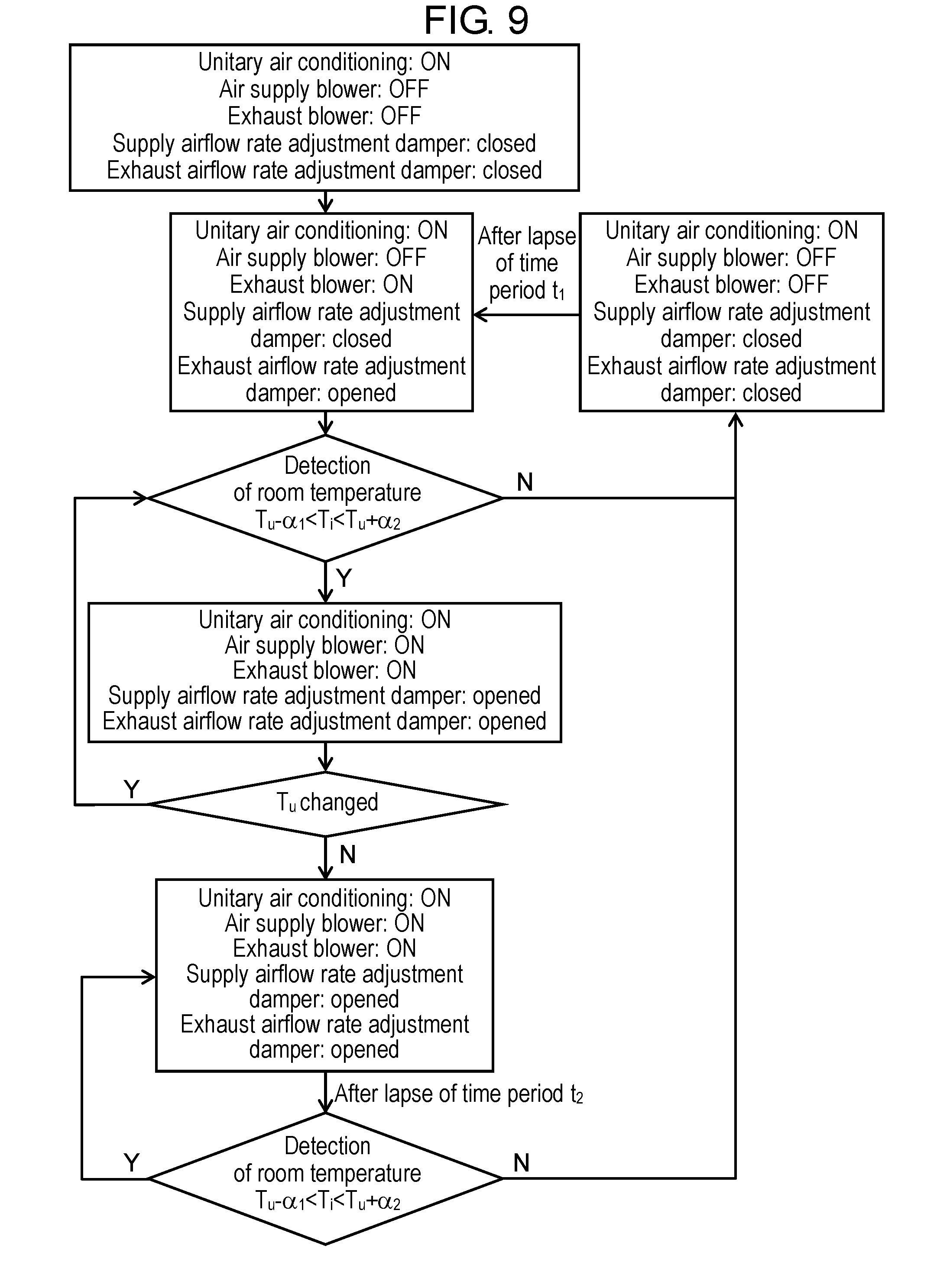
[0104] FIG. 9 is a control block diagram of the heat exchange-type ventilation device illustrated in FIG. 8.
[0105] Control operations illustrated in FIG. 9 will be specifically described. In FIG. 9, T.sub.i is a room temperature detected by room temperature detector 113, T.sub.u is a set temperature of unitary air conditioning 114, and .alpha..sub.1 and .alpha..sub.2 are predetermined temperatures.
[0106] During the halting of unitary air conditioning 114, heat exchange-type ventilation device 101 is not operated.
[0107] At the time when unitary air conditioning 114 is activated for room temperature adjustment, heat exchange-type ventilation device 101 does not immediately start a heat exchange operation.
[0108] First, controller 111 closes supply airflow rate adjustment damper 116 in air supply path 107, opens exhaust airflow rate adjustment damper 117 in exhaust path 108, and activates only exhaust blower 110 to introduce room air into heat exchange-type ventilation device 101.
[0109] When room temperature detector 113 in heat exchange-type ventilation device 101 detects room temperature T.sub.i, if T.sub.i.ltoreq.T.sub.u-.alpha..sub.1 or T.sub.u+.alpha..sub.2.ltoreq.T.sub.i, controller 111 determines that room temperature T.sub.i has not yet reached close to unitary air conditioning set temperature T.sub.u. Then, controller 111 exercises control so as to stop exhaust blower 110 and close supply airflow rate adjustment damper 116 and exhaust airflow rate adjustment damper 117.
[0110] Thus, unitary air conditioning 114 performs an indoor circulating operation. After a lapse of certain time period t.sub.1 during which the circulating operation is performed only by unitary air conditioning 114, exhaust blower 110 is activated again, exhaust airflow rate adjustment damper 117 is opened, and room temperature detector 113 detects room temperature T.sub.i.
[0111] At this time, if T.sub.u-.alpha..sub.1<T.sub.i<T.sub.u+.alpha..sub.2, controller 111 determines that room temperature T.sub.i has reached close to unitary air conditioning set temperature T.sub.u, and then controller 111 activates exhaust blower 110 and air supply blower 109 and exercises control so as to open supply airflow rate adjustment damper 116 and exhaust airflow rate adjustment damper 117.
[0112] Thus, after room temperature T.sub.i reaches close to set temperature T.sub.u of unitary air conditioning 114, heat exchange-type ventilation device 101 is activated so that ventilation to draw fresh outside air into a room while performing heat recovery can be continued. After that, if T.sub.i.ltoreq.T.sub.u-.alpha..sub.1 or T.sub.u+.alpha..sub.2.ltoreq.T.sub.i, controller 111 determines that room temperature T.sub.i has not yet reached close to unitary air conditioning set temperature T.sub.u, and then, controller 111 exercises control so as to close supply airflow rate adjustment damper 116 and exhaust airflow rate adjustment damper 117, and an indoor circulating operation is performed again only by unitary air conditioning 114 for time period
[0113] When set temperature T.sub.u of unitary air conditioning 114 is changed during the operation, controller 111 detects room temperature T.sub.i by using room temperature detector 113 to check whether T.sub.u-.alpha..sub.1<T.sub.i<T.sub.u+.alpha..sub.2. If T.sub.u-.alpha..sub.1<T.sub.i<T.sub.u+.alpha..sub.2, controller 111 opens supply airflow rate adjustment damper 116 and exhaust airflow rate adjustment damper 117 again and operates air supply blower 109 and exhaust blower 110, and thus continues the heat exchange operation.
[0114] After that, in the case where set temperature T.sub.u is not changed, after a lapse of predetermined time period t.sub.2, controller 111 detects room temperature T.sub.i again to check an indoor environment. If T.sub.i.ltoreq.T.sub.u-.alpha..sub.1 or T.sub.u+.alpha..sub.2.ltoreq.T.sub.i, controller 111 closes supply airflow rate adjustment damper 116 and exhaust airflow rate adjustment damper 117, stops air supply blower 109 and exhaust blower 110, and performs a circulating operation of unitary air conditioning 114, and thus exercises indoor temperature adjustment.
[0115] When the control illustrated in FIG. 9 is exercised, the temperature of an indoor environment is adjusted first to approximately set temperature T.sub.u of unitary air conditioning 114 at a light load, and, upon the temperature of the indoor environment reaching close to a target temperature, a heat exchange operation is performed, and thus, while taking in fresh air subjected to heat recovery, the environment can be made comfortable together with the achievement of energy saving.
[0116] Note that, in FIG. 9, if T.sub.i.ltoreq.T.sub.u-.alpha..sub.1 or T.sub.u+.alpha..sub.2.ltoreq.T.sub.i, the air supply blower and the exhaust blower are turned OFF, but at least one of the air supply blower and the exhaust blower may be kept ON. The reason for this is that, since the supply airflow rate adjustment damper and the exhaust airflow rate adjustment damper are in a closed state, air supply and exhaust can be stopped even if at least one of the air supply blower and the exhaust blower are turned ON.
[0117] FIG. 10 is a diagram illustrating another installation example of the heat exchange-type ventilation device of Embodiment 2.
[0118] As illustrated in FIG. 10, supply airflow rate adjustment damper 116 and exhaust airflow rate adjustment damper 117 may be provided inside a body of heat exchange-type ventilation device 101.
[0119] Alternatively, although not illustrated, supply airflow rate adjustment damper 116 in FIG. 6 may be provided inside the body of heat exchange-type ventilation device 101.
[0120] Hereinafter, the present embodiment will be additionally described.
[0121] Unitary air conditioning 114 includes a concept of whole building air conditioning or central air conditioning.
[0122] In the embodiment above, controller 111 is provided in heat exchange-type ventilation device 101, but may not be provided in heat exchange-type ventilation device 101. In this case, control is exercised by controller 111 located at some distance from heat exchange-type ventilation device 101.
[0123] .alpha..sub.1 is a constant which is any value, for example, in a range of 0.1.degree. C. to 3.degree. C., such as 1.degree. C.
[0124] .alpha..sub.2 is a constant which is any value, for example, in a range of 0.1.degree. C. to 3.degree. C., such as 1.degree. C.
[0125] The expression "a supply airflow rate adjustment damper is closed" includes a case in which a supply airflow rate adjustment damper is fully closed. The expression "an exhaust airflow rate adjustment damper is closed" includes a case in which an exhaust airflow rate adjustment damper is fully closed.
[0126] In the embodiment above, during the halting of unitary air conditioning 114, heat exchange-type ventilation device 101 is not operated, but, even during the halting of unitary air conditioning 114, heat exchange-type ventilation device 101 is available for operation. In this case, with the additional provision of a communication port communicating with a room to circulating air path 115, an air path that does not pass through unitary air conditioning 114 can be formed, whereby a heat exchange operation can be smoothly performed. Note that the communication port provided in circulating air path 115 can be preferably opened and closed, and, when the unitary air conditioning is ON, the communication port is preferably in a closed state, and in contrast, when the unitary air conditioning is OFF, the communication port is preferably in an open state.
[0127] In Embodiment 2, air supply path 107 is connected to circulating air path 115 upstream from unitary air conditioning 114, but may be connected to circulating air path 115 downstream from unitary air conditioning 114.
[0128] The heat exchange-type ventilation device according to the present disclosure has been described above based on the embodiments, but the present disclosure is not limited to the embodiments. Various modifications to the embodiments that could be conceived by those skilled in the art and combinations of constituent elements in different embodiments may be included within the present disclosure, without departing from the spirit of the present disclosure.
INDUSTRIAL APPLICABILITY
[0129] The ventilation device according to the present disclosure is also useful as, for example, a duct ventilation device for heat exchange between outside air and room air or a duct air conditioning device.
REFERENCE MARKS IN THE DRAWINGS
[0130] 1, 101 . . . heat exchange-type ventilation device
[0131] 2, 102 . . . outside-air inlet port
[0132] 3, 103 . . . room-air exhaust port
[0133] 4, 104 . . . outside-air supply port
[0134] 5, 105 . . . room-air inlet port
[0135] 6, 106 . . . heat exchange element
[0136] 7, 107 . . . air supply path
[0137] 8, 108 . . . exhaust path
[0138] 9, 109 . . . air supply blower
[0139] 10, 110 . . . exhaust blower
[0140] 11, 111 . . . controller
[0141] 12, 112 . . . air purifying filter
[0142] 13 . . . unitary air conditioning
[0143] 14 . . . circulating air path
[0144] 15 . . . airflow rate adjustment damper
[0145] 16 . . . airflow rate adjustment damper
[0146] 17 . . . current detector
[0147] 113 . . . room temperature detector
[0148] 114 . . . unitary air conditioning
[0149] 115 . . . circulating air path
[0150] 116 . . . supply airflow rate adjustment damper
[0151] 117 . . . exhaust airflow rate adjustment damper
[0152] 202 . . . outside-air inlet port
[0153] 203 . . . heat exchange element
[0154] 209 . . . air supply blower
[0155] 210 . . . exhaust blower
* * * * *
D00000
D00001
D00002
D00003
D00004
D00005
D00006
D00007
D00008
D00009
D00010
D00011
XML
uspto.report is an independent third-party trademark research tool that is not affiliated, endorsed, or sponsored by the United States Patent and Trademark Office (USPTO) or any other governmental organization. The information provided by uspto.report is based on publicly available data at the time of writing and is intended for informational purposes only.
While we strive to provide accurate and up-to-date information, we do not guarantee the accuracy, completeness, reliability, or suitability of the information displayed on this site. The use of this site is at your own risk. Any reliance you place on such information is therefore strictly at your own risk.
All official trademark data, including owner information, should be verified by visiting the official USPTO website at www.uspto.gov. This site is not intended to replace professional legal advice and should not be used as a substitute for consulting with a legal professional who is knowledgeable about trademark law.