Heat Source Unit For Refrigeration Apparatus
Kobayashi; Keiko ; et al.
U.S. patent application number 16/235518 was filed with the patent office on 2019-07-04 for heat source unit for refrigeration apparatus. This patent application is currently assigned to DAIKIN INDUSTRIES, LTD.. The applicant listed for this patent is DAIKIN INDUSTRIES, LTD.. Invention is credited to Ying Ying Ji, Keiko Kobayashi.
| Application Number | 20190203955 16/235518 |
| Document ID | / |
| Family ID | 67058114 |
| Filed Date | 2019-07-04 |


| United States Patent Application | 20190203955 |
| Kind Code | A1 |
| Kobayashi; Keiko ; et al. | July 4, 2019 |
HEAT SOURCE UNIT FOR REFRIGERATION APPARATUS
Abstract
A heat source unit for a refrigeration apparatus, including: a casing; a heat exchanger disposed in an internal space of the casing, and that performs heat exchange between a refrigerant and air; a fan disposed in the internal space of the casing, and that horizontally blows out air passing through the heat exchanger; a first shut-off valve; and a second shut-off valve larger in diameter than the first shut-off valve; wherein the heat source unit further includes an above-shut-off-valves member disposed in the casing, positioned above the first shut-off valve and the second shut-off valve, and having at least one vertically penetrating wiring hole. The second shut-off valve is disposed below the first shut-off valve.
| Inventors: | Kobayashi; Keiko; (Osaka, JP) ; Ji; Ying Ying; (Osaka, JP) | ||||||||||
| Applicant: |
|
||||||||||
|---|---|---|---|---|---|---|---|---|---|---|---|
| Assignee: | DAIKIN INDUSTRIES, LTD. Osaka JP |
||||||||||
| Family ID: | 67058114 | ||||||||||
| Appl. No.: | 16/235518 | ||||||||||
| Filed: | December 28, 2018 |
| Current U.S. Class: | 1/1 |
| Current CPC Class: | F24F 1/46 20130101; F24F 1/16 20130101; F25B 41/043 20130101; F25B 41/04 20130101; F24F 1/32 20130101; F24F 1/38 20130101; F25B 2500/01 20130101 |
| International Class: | F24F 1/16 20060101 F24F001/16; F24F 1/38 20060101 F24F001/38; F24F 1/32 20060101 F24F001/32; F25B 41/04 20060101 F25B041/04 |
Foreign Application Data
| Date | Code | Application Number |
|---|---|---|
| Dec 28, 2017 | JP | 2017-254910 |
Claims
1. A heat source unit for a refrigeration apparatus, comprising: a casing; a heat exchanger disposed in an internal space of the casing and that performs heat exchange between a refrigerant and air; a fan disposed in the internal space of the casing and that horizontally blows out air passing through the heat exchanger; a first shut-off valve; a second shut-off valve larger in diameter than the first shut-off valve; and an above-shut-off-valves member disposed in the casing, positioned above the first shut-off valve and the second shut-off valve, and having at least one vertically penetrating wiring hole, wherein the second shut-off valve is disposed below the first shut-off valve.
2. The heat source unit for a refrigeration apparatus according to claim 1, wherein the first shut-off valve and the second shut-off valve are disposed in a range of 3/4 or less of a distance from a bottom surface of the casing to the wiring hole.
3. The heat source unit for a refrigeration apparatus according to claim 1, wherein the first shut-off valve and the wiring hole do not overlap in a plan view of the casing.
4. The heat source unit for a refrigeration apparatus according to claim 1, wherein the wiring hole is disposed as one of a plurality of wiring holes of the above-shut-off-valves member; and the first shut-off valve and at least one of the plurality of wiring holes do not overlap in a plan view of the casing.
5. The heat source unit for a refrigeration apparatus according to claim 1, further comprising an electric component assembly disposed in the internal space of the casing and above the wiring hole.
6. The heat source unit for a refrigeration apparatus according to claim 1, wherein the first shut-off valve and the second shut-off valve each have a connection port that opens toward a front-surface side or a back-surface side of the casing.
7. The heat source unit for a refrigeration apparatus according to claim 1, wherein the above-shut-off-valves member partitions the internal space of the casing and a shut-off valve placement space in which the first shut-off valve and the second shut-off valve are disposed.
8. The heat source unit for a refrigeration apparatus according to claim 7, wherein the casing has cut-out portions proximal to the first shut-off valve and the second shut-off valve; and the cut-out portions of the casing face the shut-off valve placement space.
9. The heat source unit for a refrigeration apparatus according to claim 1, wherein the first shut-off valve and the second shut-off valve are disposed not to protrude from a virtual cuboid defined by a top surface, bottom surface, front surface, back surface, left-side surface, and right-side surface of the casing.
Description
TECHNICAL FIELD
[0001] A heat source unit for a refrigeration apparatus, provided with a fan that horizontally blows out air passing through a heat exchanger.
BACKGROUND
[0002] Conventionally, there have been heat source units for refrigeration apparatuses of which internal spaces are provided with fans that horizontally blow out air passing through heat exchangers, as shown in Patent Literature 1 (Japanese Laid-open Patent Publication No. 2009-24903). A heat source unit is provided with a shut-off valve. A refrigerant connection pipe for circulating refrigerant with a usage unit is connected to the shut-off valve. Electric wire is drawn out from an internal space of the heat source unit.
[0003] In the conventional heat source unit described above, the space that can be used when drawing the electric wire out from the internal space is small, and electric wire installation and other work is therefore sometimes difficult.
SUMMARY
[0004] A heat source unit for a refrigeration apparatus according to one or more embodiments comprises a casing, a heat exchanger that performs heat exchange between a refrigerant and air, a fan that horizontally blows out air passing through the heat exchanger, a first shut-off valve, and a second shut-off valve larger in diameter than the first shut-off valve. The heat exchanger and the fan are placed in an internal space of the casing. The heat source unit further has an above-shut-off-valve member. The above-shut-off-valve member is provided to the casing so as to be positioned above the first shut-off valve and the second shut-off valve, and at least one vertically penetrating wiring hole is formed in the above-shut-off-valve member. The second shut-off valve is placed below the first shut-off valve.
[0005] In one or more embodiments, because the large-diameter second shut-off valve can be placed so as to be downwardly set apart from the wiring hole, it is possible to enlarge a space that can be used to draw an electric wire out from the internal space of the casing through the wiring hole, and work such as the installation of the electric wire can be performed easily.
[0006] According to one or more embodiments of a heat source unit for a refrigeration apparatus, the first shut-off valve and the second shut-off valve are placed in a range of 3/4 or less of a height (distance) from a bottom surface of the casing to the wiring hole.
[0007] In one or more embodiments, because the small-diameter first shut-off valve can be placed so as to be downwardly set apart from the wiring hole, it is possible to further enlarge the space that can be used to draw the electric wire out from the internal space of the casing through the wiring hole, and work such as the installation of the electric wire can be performed even more easily.
[0008] According to one or more embodiments of a heat source unit for a refrigeration apparatus, the first shut-off valve is placed so as not to overlap the wiring hole in a plan view of the casing.
[0009] In one or more embodiments, because the first shut-off valve is not placed directly below the wiring hole, it is possible to further enlarge the space that can be used to draw the electric wire out from the internal space of the casing through the wiring hole, and work such as the installation of the electric wire can be performed even more easily.
[0010] According to one or more embodiments of a heat source unit for a refrigeration apparatus, a plurality of the wiring holes are present as the wiring holes, and the first shut-off valve is placed so as not to overlap at least one of the plurality of wiring holes in a plan view of the casing.
[0011] In one or more embodiments, because the first shut-off valve is not placed directly below at least one wiring hole, it is possible to further enlarge the space that can be used to draw the electric wire out from the internal space of the casing through the wiring hole, and work such as the installation of the electric wire can be performed even more easily.
[0012] According to one or more embodiments of a heat source unit for a refrigeration apparatus, further having an electric component assembly placed in the internal space of the casing so as to be positioned above the wiring holes.
[0013] In one or more embodiments, because the electric wire extending from the electric component assembly can be guided to the wiring hole by being directed downward, contact with a refrigerant pipe placed in the internal space can be avoided, and work such as the installation of the electric wire can be performed even more easily.
[0014] According to one or more embodiments of a heat source unit for a refrigeration apparatus, the first shut-off valve and the second shut-off valve each have a connection port that opens toward a front-surface side or a back-surface side of the casing.
[0015] In one or more embodiments, refrigerant connection pipes can be easily drawn out toward the front-surface side or back-surface side of the casing due to being connected to the connection ports of the shut-off valves, and work such as the installation of the refrigerant connection pipes can be performed easily.
[0016] According to one or more embodiments of a heat source unit for a refrigeration apparatus, the above-shut-off-valve member partitions the internal space of the casing and a shut-off valve placement space in which the first shut-off valve and the second shut-off valve are placed.
[0017] According to one or more embodiments of a heat source unit for a refrigeration apparatus, portions of the casing that are in proximity to the first shut-off valve and the second shut-off valve are cut out, and cut-out portions of the casing face the shut-off valve placement space.
[0018] In one or more embodiments, the shut-off valve placement space can be accessed through the cut-out portions of the casing, and it is easy to operate the shut-off valves and/or perform the work of connecting the refrigerant connection pipes to the shut-off valves.
[0019] According to one or more embodiments of a heat source unit for a refrigeration apparatus, the first shut-off valve and the second shut-off valve are placed so as not to protrude from a virtual cuboid defined by a top surface, bottom surface, front surface, back surface, left-side surface, and right-side surface of the casing.
[0020] In one or more embodiments, because there is no need for a shut-off valve cover or similar member provided so as to protrude sideways from a side surface of the casing, the space for installing and/or packing the heat source unit can be reduced.
BRIEF DESCRIPTION OF THE DRAWINGS
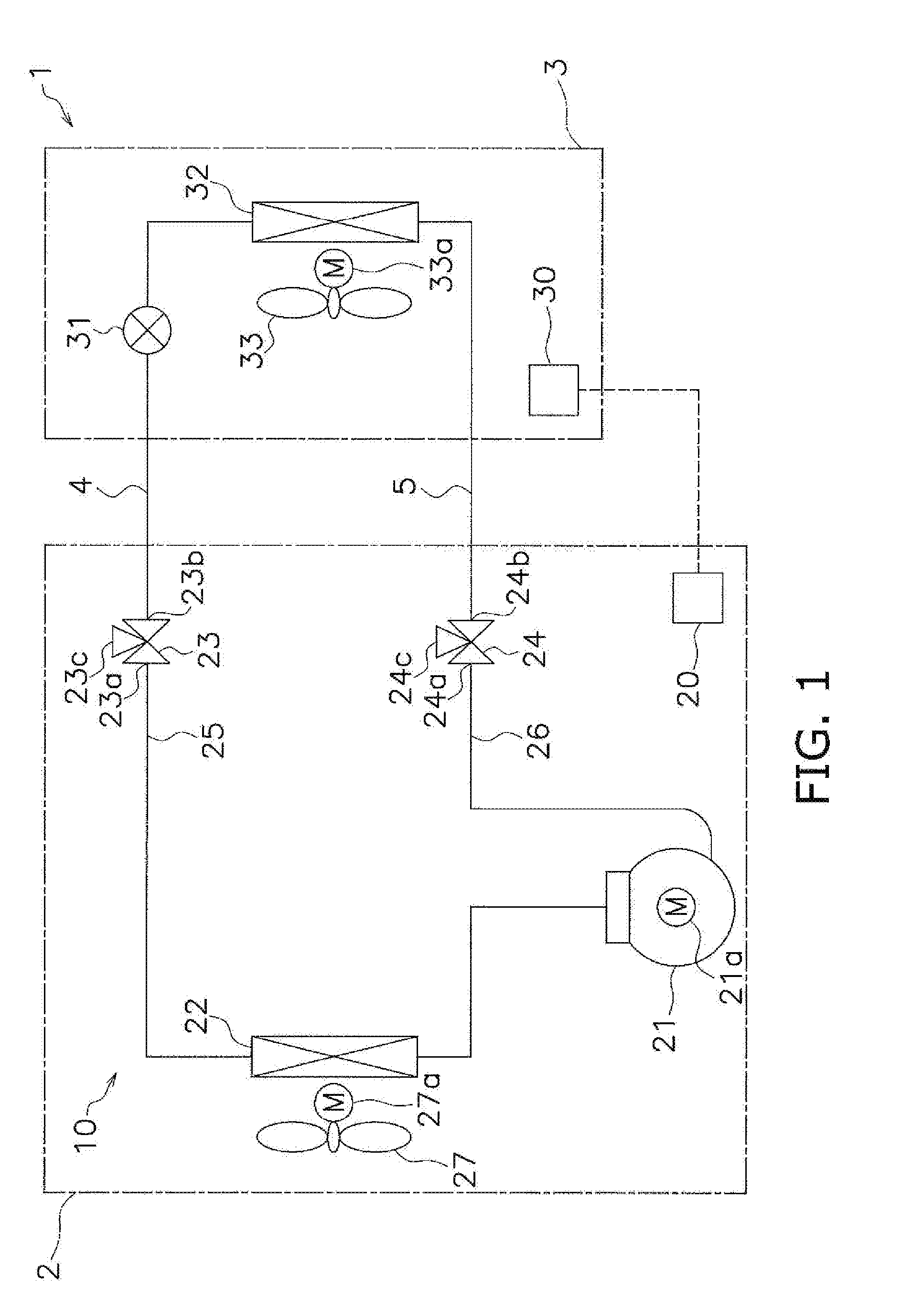
[0021] FIG. 1 is a schematic configuration diagram of an air conditioning apparatus serving as a refrigeration apparatus that employs an outdoor unit serving as a heat source unit according to one or more embodiments of the present invention;
[0022] FIG. 2 is a perspective view showing an external view of the outdoor unit;
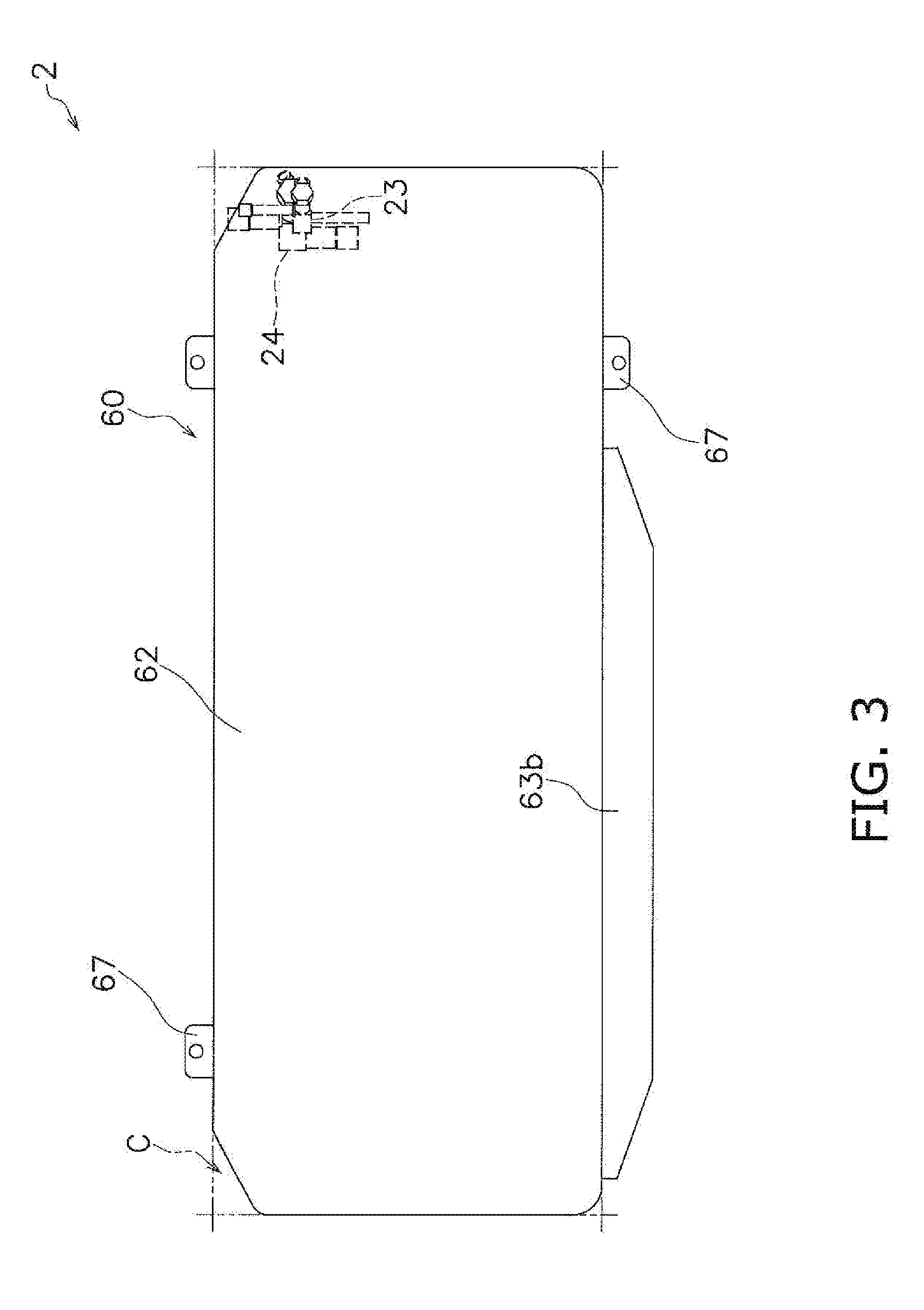
[0023] FIG. 3 is a plan view of the outdoor unit (with a shut-off valve depicted in dashed lines);
[0024] FIG. 4 is a plan view of the outdoor unit (with a top panel taken off);
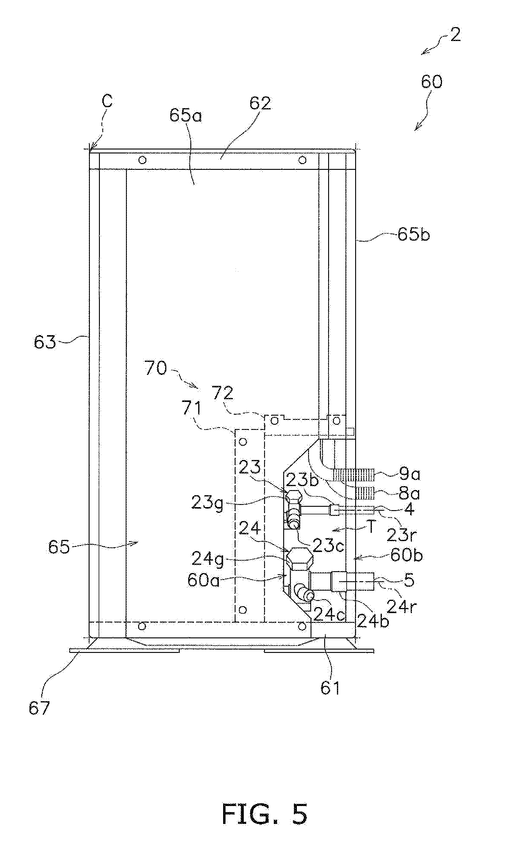
[0025] FIG. 5 is a right-side surface view of the outdoor unit;
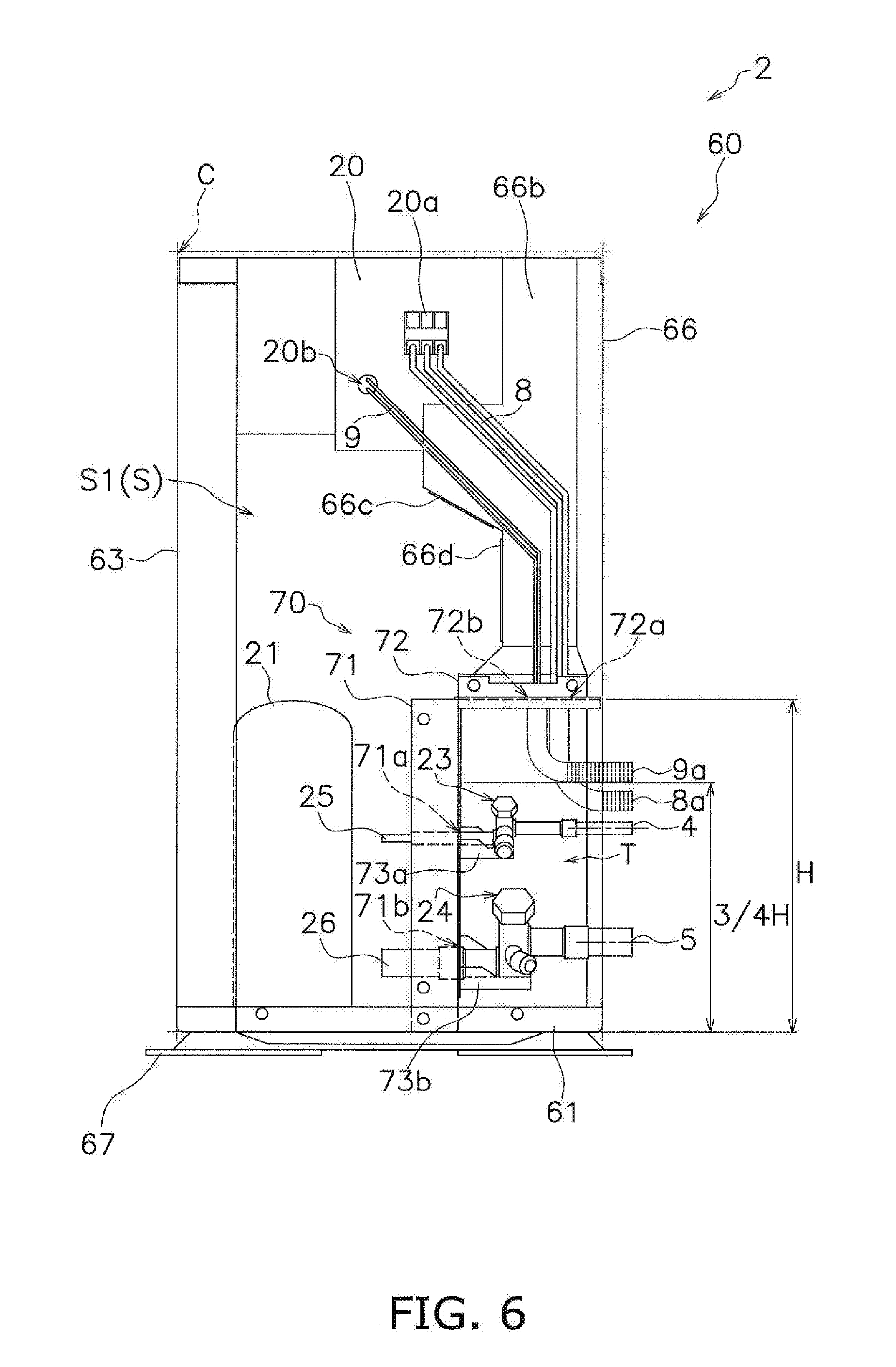
[0026] FIG. 6 shows the outdoor unit with the top panel and a right-side panel removed from the unit as depicted in FIG. 5;
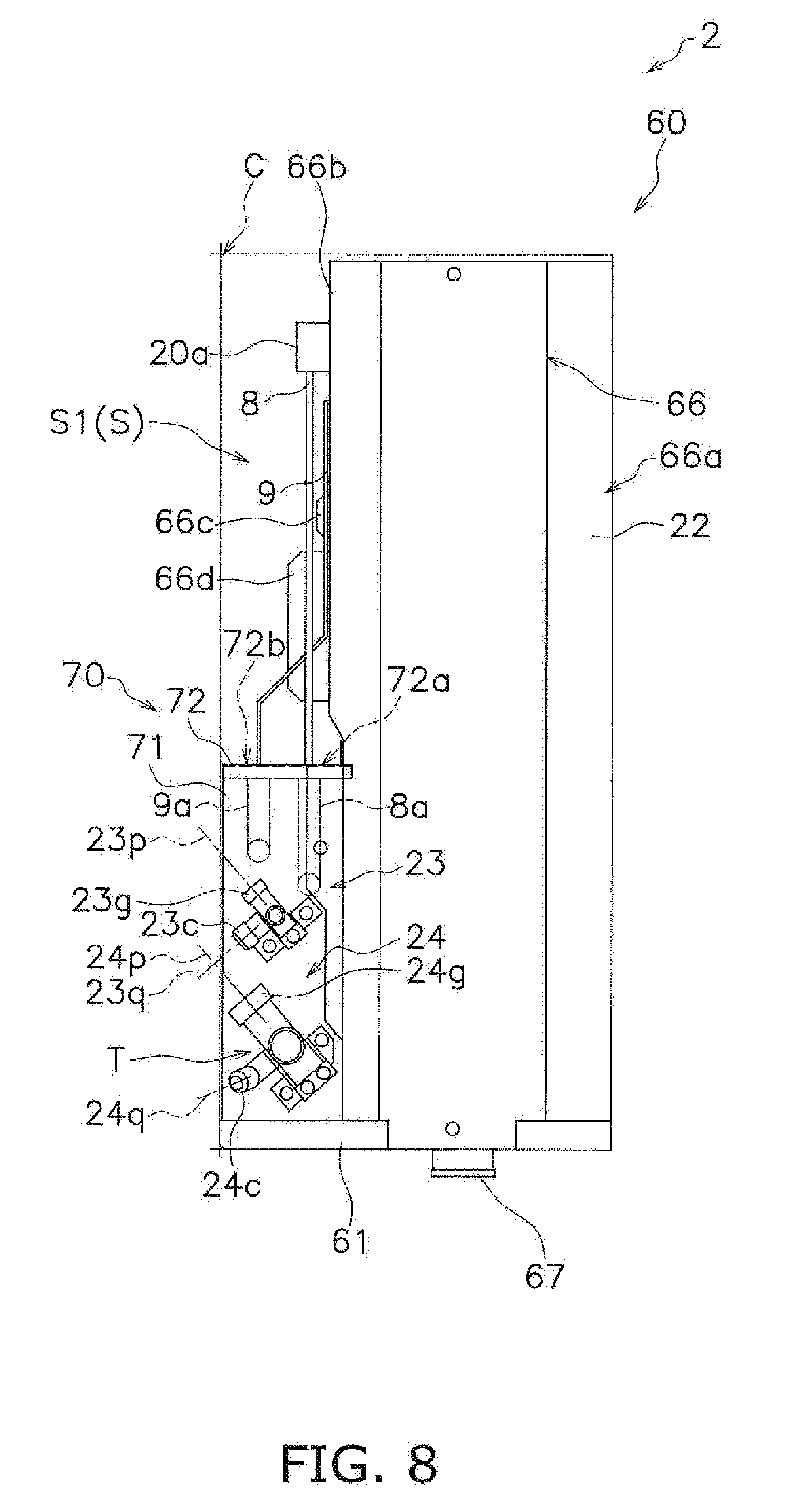
[0027] FIG. 7 is a rear view of the outdoor unit (showing only the portion near the right-side surface);
[0028] FIG. 8 shows the outdoor unit with the top panel and the right-side panel removed from the unit as depicted in FIG. 7;
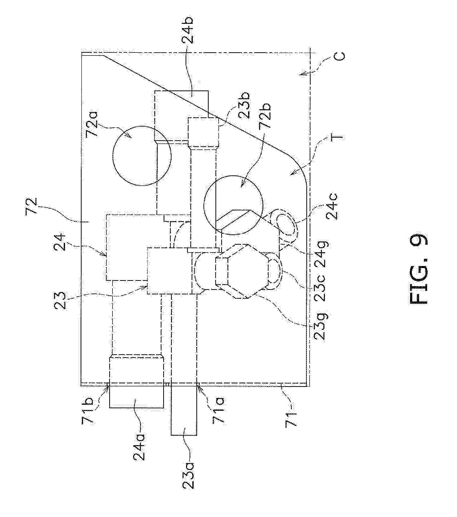
[0029] FIG. 9 shows the positional relationship between wiring holes and shut-off valves in a plan view of a casing according to one or more embodiments; and
[0030] FIG. 10 shows a shut-off valve (with a valve-operating part facing upward) according to one or more embodiments.
DETAILED DESCRIPTION
[0031] Below is a description, made with reference to the drawings, of a heat source unit for a refrigeration apparatus according to one or more embodiments.
[0032] (1) Configuration of air conditioning apparatus FIG. 1 is a schematic configuration diagram of an air conditioning apparatus 1 serving as a refrigeration apparatus that employs an outdoor unit 2 serving as a heat source unit according to one or more embodiments of the present invention.
[0033] <Overall>
[0034] The air conditioning apparatus 1 as a refrigeration apparatus is able to perform cooling of a room in a building, etc., by performing a vapor-compression refrigeration cycle. The air conditioning apparatus 1 mainly has the outdoor unit 2 serving as a heat source unit, an indoor unit 3 serving as a usage unit, and a liquid refrigerant connection pipe 4 and gas refrigerant connection pipe 5 that connect the outdoor unit 2 and the indoor unit 3. A vapor-compression refrigeration circuit 10 of the air conditioning apparatus 1 is configured by the outdoor unit 2 and the indoor unit 3 being connected via the refrigerant connection pipes 4, 5.
[0035] <Indoor Unit>
[0036] The indoor unit 3 is installed in a building. The indoor unit 3, as described above, is connected to the outdoor unit 2 via the liquid refrigerant connection pipe 4 and the gas refrigerant refrigerant connection pipe 5, thus configuring part of the refrigeration circuit 10. The indoor unit 3 mainly has an indoor expansion valve 31 and an indoor heat exchanger 32.
[0037] The indoor expansion valve 31 is an electric expansion valve that, when in operation, adjusts the flow rate of refrigerant flowing through the indoor heat exchanger 32 while decompressing the refrigerant to a low pressure in the refrigeration cycle, and is connected between the liquid refrigerant connection pipe 4 and a liquid-side end of the indoor heat exchanger 32.
[0038] The indoor heat exchanger 32 is a heat exchanger that, when in operation, functions as an evaporator of refrigerant at a low pressure in the refrigeration cycle and cools indoor air. The liquid-side end of this indoor heat exchanger is connected to the indoor expansion valve 31, and a gas-side end is connected to the gas refrigerant connection pipe 5.
[0039] The indoor unit 3 has an indoor fan 33 for drawing indoor air into the indoor unit 3, and supplying air passing through the indoor heat exchanger 32 as supply air into the room after the air has exchanged heat with the refrigerant in the indoor heat exchanger 32. Specifically, the indoor unit 3 has an indoor fan 33 as a fan that supplies the indoor heat exchanger 32 with indoor air serving as a heat source for the refrigerant flowing through the indoor heat exchanger 32. The indoor fan 33 is driven by an indoor fan motor 33a.
[0040] Furthermore, the indoor unit 3 has an indoor-side electric component assembly 30 that functions as an indoor-side control part to control the actions of the components configuring the indoor unit 3. The indoor-side electric component assembly 30 has a control board and other electric components, and this assembly is designed to be capable of communicating through control signals, etc., with the outdoor unit 2.
[0041] <Outdoor Unit>
[0042] The outdoor unit 2 is installed on the outside of the building. The outdoor unit 2, as described above, is connected to the indoor unit 3 via the liquid refrigerant connection pipe 4 and the gas refrigerant connection pipe 5, thus configuring part of the refrigeration circuit 10. The outdoor unit 2 mainly has a compressor 21, an outdoor heat exchanger 22, a liquid-side shut-off valve 23 serving as a first shut-off valve, and a gas-side shut-off valve 24 serving as a second shut-off valve.
[0043] The compressor 21 is a device that, when in operation, compresses refrigerant at a low pressure in the refrigeration cycle to a high pressure. In one or more embodiments, a compressor having a hermetically sealed structure, in which a positive displacement compression element (not shown) is rotatably driven by a compressor motor 21a, is employed as the compressor 21. A discharge-side end of the compressor 21 is connected to a gas-side end of the outdoor heat exchanger 22, and an intake-side end of the compressor 21 is connected to the gas-side shut-off valve 24. In one or more embodiments, the intake-side end of the compressor 21 and the gas-side shut-off valve 24 are connected by an outdoor-side gas refrigerant pipe 26.
[0044] The outdoor heat exchanger 22 is a heat exchanger that, when in operation, functions as a radiator for refrigerant at a high pressure in the refrigeration cycle. The gas-side end of this outdoor heat exchanger is connected to the discharge-side end of the compressor 21, and a liquid-side end is connected to the liquid-side shut-off valve 23. In one or more embodiments, the liquid-side end of the outdoor heat exchanger 22 and the liquid-side shut-off valve 23 are connected by an outdoor-side liquid refrigerant pipe 25.
[0045] The liquid-side shut-off valve 23 and the gas-side shut-off valve 24 are manual valves provided to parts connecting with external devices or pipes (specifically, the liquid refrigerant connection pipe 4 and the gas refrigerant connection pipe 5). In the liquid-side shut-off valve 23, an outdoor-side connection port 23a, which is on an outdoor-side end of the valve, is connected to the outdoor-side liquid refrigerant pipe 25, and an indoor-side connection port 23b, which is on an indoor-side end, is connected to the liquid refrigerant connection pipe 4. In the gas-side shut-off valve 24, an outdoor-side connection port 24a, which is on an outdoor-side end of the valve, is connected to the outdoor-side gas refrigerant pipe 26, and an indoor-side connection port 24b, which is on an indoor-side end, is connected to the gas refrigerant connection pipe 5. The liquid-side shut-off valve 23 and the gas-side shut-off valve 24 are respectively provided with service ports 23c, 24c to which a charge hose is connected to fill refrigerant.
[0046] The outdoor unit 2 has an outdoor fan 27 for drawing outdoor air into the outdoor unit 2, and blowing the air passing through the outdoor heat exchanger 22 out of the room after the air has exchanged heat with the refrigerant in the outdoor heat exchanger 22. Specifically, the outdoor unit 2 has the outdoor fan 27 as a fan that supplies the outdoor heat exchanger 22 with outdoor air serving as a cooling source for the refrigerant flowing through the outdoor heat exchanger 22. The outdoor fan 27 is driven by an outdoor fan motor 27a.
[0047] Furthermore, the outdoor unit 2 has an outdoor-side electric component assembly 20 that functions as an outdoor-side control part to control the actions of the components configuring the outdoor unit 2. The outdoor-side electric component assembly 20 has a control board and other electric components, and this assembly is designed to be capable of communicating through control signals, etc., with the indoor unit 3 (the indoor-side electric component assembly 30 in one or more embodiments).
[0048] <Refrigerant Connection Pipes>
[0049] The refrigerant connection pipes 4, 5 are constructed on-site when the air conditioning apparatus 1 is installed in a building or another installation site. One end of the liquid refrigerant connection pipe 4 is connected to the indoor-side connection port 23b of the liquid-side shut-off valve 23 of the outdoor unit 2, and the other end of the liquid refrigerant connection pipe 4 is connected to the indoor expansion valve 31 of the indoor unit 3. One end of the gas refrigerant connection pipe 5 is connected to the indoor-side connection port 24b of the gas-side shut-off valve 24 of the outdoor unit 2, and the other end of the gas refrigerant connection pipe 5 is connected to a gas-side end of the indoor heat exchanger 32 of the indoor unit 3.
[0050] (2) Configuration of Outdoor Unit
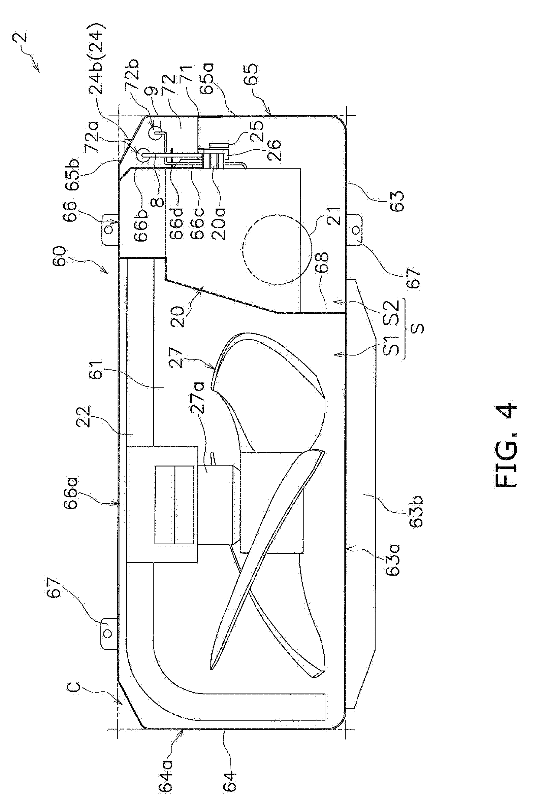
[0051] FIG. 2 is a perspective view showing an external view of the outdoor unit 2. FIG. 3 is a plan view of the outdoor unit 2 (with the shut-off valves 23, 24 shown in dashed lines). FIG. 4 is a plan view of the outdoor unit 2 (with a top-surface panel 62 removed). FIG. 5 is a right-side view of the outdoor unit 2. FIG. 6 shows the outdoor unit with the top-surface panel 62 and a right-side panel 65 removed from the unit as depicted in FIG. 5. FIG. 7 is a rear view of the outdoor unit 2 (showing only the portion near the right side). FIG. 8 shows the outdoor unit with the top-surface panel 62 and the right-side panel 65 removed from the unit as depicted in FIG. 7. FIG. 9 shows the positional relationship between wiring holes 72a, 72b and the shut-off valves 23, 24 in a plan view of a casing 60. FIG. 10 shows the liquid-side shut-off valve 23 (with a valve-operating part 23g facing upward). In the following description, the terms "up," "down," "left," "right," "front," "rear," "lateral," "top surface," "bottom surface," "front surface," and "back surface," unless otherwise specified, refer to directions and/or surfaces assuming that the "front surface" is the left-diagonal-facing surface of the outdoor unit 2 shown in FIG. 2.
[0052] <Basic Configuration>
[0053] First, the basic configuration of the outdoor unit 2 shall be described.
[0054] The outdoor unit 2 is a heat source unit with a structure (a "trunk-type structure") having the substantially cuboid box-shaped casing 60, the outdoor heat exchanger 22 serving as a heat exchanger that is placed in an internal space S of the casing 60 and that performs heat exchange between the refrigerant and air, and the outdoor fan 27 serving as a fan that is placed in the internal space S of the casing 60 and that horizontally blows out air passing through the outdoor heat exchanger 22. The outdoor unit 2 mainly has: the casing 60; the outdoor fan 27; refrigerant circuit structural components that configure part of the refrigeration circuit 10, including the compressor 21, the outdoor heat exchanger 22, and/or other devices, the shut-off valves 23, 24 and other valves, and the refrigerant pipes 25, 26 and other refrigerant pipes; and the outdoor-side electric component assembly 20.
[0055] The casing 60 mainly has a bottom-surface panel 61, the top-surface panel 62, and peripheral panels (front-surface panel 63, left-side panel 64, right-side panel 65, and back-surface panel 66) forming the front surface, back surface, left-side surface, and right-side surface of the casing 60.
[0056] The bottom-surface panel 61 is a laterally extending panel-shaped member forming the bottom surface of the casing 60. In a plan view of the casing 60, the bottom-surface panel 61 has a rectangular shape in which the left-rear corner and the right-rear corner are chamfered. A lower surface of the bottom-surface panel 61 is provided with a fixing leg 67 fixed to an on-site installation surface.
[0057] The top-surface panel 62 is a laterally extending panel-shaped member forming a top surface of the casing 60. In a plan view of the casing 60, the top-surface panel 62, similar to the bottom-surface panel 61, has a rectangular shape in which the left-rear corner and the right-rear corner are chamfered. The top-surface panel 62 is fixed by screws, etc., to the front-surface panel 63, the left-side panel 64, the right-side panel 65, and the back-surface panel 66.
[0058] The front-surface panel 63 is one peripheral panel of the casing 60. The front-surface panel 63 is a panel-shaped member forming a front surface of the casing 60, a portion on the front-surface-side end of the left-side surface, and a portion on the front-surface-side end of the right-side surface. A lower part of the front-surface panel 63 is fixed by screws, etc., to the bottom-surface panel 61. A portion near the left-side surface of the front-surface panel 63 is provided with a blow-out port 63a for blowing out to the exterior air that has been taken into the internal space S from the back-surface and left-side surface of the casing 60 by the outdoor fan 27. A fan grill 63b is provided to the blow-out port 63a.
[0059] The left-side panel 64 is a panel-shaped member forming the left-side surface (excluding the portion on the front-surface-side end of the left-side surface in one or more embodiments) of the casing 60 and the left-side-surface end of the back surface, thus configuring part of the peripheral panels of the casing 60. A lower part of the left-side panel 64 is fixed by screws, etc., to the bottom-surface panel 61. In the left-side panel 64 is formed an intake port 64a for air taken into the internal space S of the casing 60 by the outdoor fan 27.
[0060] The right-side panel 65 is a panel-shaped member forming the right-side surface (excluding the portion on the front-surface-side end of the right-side surface in one or more embodiments) of the casing 60 and the right-side-surface end of the back surface, thus configuring part of the peripheral panels of the casing 60. A lower part of the right-side panel 65 is fixed by screws, etc., to the bottom-surface panel 61.
[0061] The back-surface panel 66 is a panel-shaped member forming the back surface (excluding the right-side-surface end portion and near-left-side-surface portion of the back surface) of the casing 60, thus configuring part of the peripheral panels of the casing 60. A lower part of the back-surface panel 66 is fixed by screws, etc., to the bottom-surface panel 61. In the back-surface panel 66 is formed an intake port 66a for air taken into the internal space S of the casing 60 by the outdoor fan 27.
[0062] A partitioning panel 68 is provided inside the casing 60. The partitioning panel 68 is a panel-shaped member extending vertically and in the front-rear direction over the bottom-surface panel 61, and is disposed so as to partition the internal space S of the casing 60 into two left and right spaces (fan compartment 51, machinery compartment S2). In a plan view of the casing 60, the partitioning panel 68 extends toward the back-surface side from a right-side portion of the blow-out port 63a of the front-surface panel 63, and reaches a right-end part of the substantially L-shaped outdoor heat exchanger 22, which is disposed so as to extend along the back surface from the left-side surface of the casing 60. A lower part of the partitioning panel 68 is fixed by screws, etc., to the bottom-surface panel 61, a front part is fixed by screws, etc., to the front-surface panel 63, and a rear part is fixed by screws, etc., to the right-end part of the outdoor heat exchanger 22.
[0063] The compressor 21 is in the shape of an upright cylinder, and is disposed in the machinery compartment S2. The compressor 21 is provided over the bottom-surface panel 61.
[0064] In a plan view of the casing 60, the outdoor heat exchanger 22 is substantially L-shaped, and is disposed in the fan compartment S1. The outdoor heat exchanger 22 is provided over the bottom-surface panel 61 so as to extend along the back surface from the left-side surface of the casing 60.
[0065] The outdoor fan 27 is a propeller fan and is disposed in the fan compartment 51. The outdoor fan 27 is provided so as to face the blow-out port 63a in a front side of the outdoor heat exchanger 22. The outdoor fan motor 27a is provided between the outdoor fan 27 and the outdoor heat exchanger 22 in the front-rear direction.
[0066] The outdoor-side electric component assembly 20 is a component in which the control board and other electric components are assembled, and is disposed in the machinery compartment S2. The outdoor-side electric component assembly 20 is provided in an upper part of the machinery compartment S2.
[0067] Though not depicted in FIGS. 4, 6, and 8, refrigeration circuit structural components other than the compressor 21, the outdoor heat exchanger 22, and the shut-off valves 23, 24 are also disposed in the internal space S of the casing 60.
[0068] <Shut-Off Valves and Structures of Peripheries Thereof)
[0069] Next, the shut-off valves 23, 24 of the outdoor unit 2 and the structures of the peripheries thereof shall be described.
[0070] The liquid-side shut-off valve 23 mainly has a valve main body 23d in which is formed a flow channel 23e through which refrigerant flows, a valve body 23f that opens and closes the flow channel 23e, and a valve-operating part 23g that operates the valve body 23f. Specifically, using as a reference a state in which the valve-operating part 23g faces upward, formed in the valve main body 23d are the substantially horizontally facing flow channel 23e, the outdoor-side connection port 23a, which is an opening corresponding to one end of the flow channel 23e, and the indoor-side connection port 23b, which is an opening corresponding to the other end of the flow channel 23e. Also provided to the valve main body 23d are the valve-operating part 23g, which protrudes upward from some point in the flow channel 23e, and a service port 23c, which protrudes in a direction intersecting the flow channel 23e and the valve-operating part 23g. The valve body 23f is threaded into the valve-operating part 23g so as to be capable of moving vertically. In an upper end of the valve body 23f is formed an engaging part 23h, which is composed of a concaved portion or groove into which a hexagonal wrench, a driver, or another tool fits. A valve cover 23i is detachably threaded into the valve-operating part 23g. A tip end of the service port 23c serves as a nozzle part to which a charge hose, etc., can be connected. A center line of the valve-operating part 23g is denoted as 23p, a center line of the service port 23c is denoted as 23q, and a center line of the indoor-side connection port 23b is denoted as 23r.
[0071] The gas-side shut-off valve 24 is larger in diameter than the liquid-side shut-off valve 23, and is similar in structure to the liquid-side shut-off valve 23. Therefore, for the structure of the gas-side shut-off valve 24, the symbols 23a to 23i and 23p to 23r, which indicate the components of the liquid-side shut-off valve 23, are replaced with the symbols 24a to 24i and 24p to 24r, and descriptions of these components are omitted.
[0072] The liquid-side shut-off valve 23 and the gas-side shut-off valve 24 are disposed so as not to protrude from a virtual cuboid C defined by the top surface, bottom surface, front surface, back surface, left-side surface, and right-side surface of the casing 60. In one or more embodiments, the virtual cuboid C is a cuboid-shaped spatial area formed by surfaces virtually extending in the front-rear and lateral directions through the top surface and bottom surface of the casing 60 (in one or more embodiments, surfaces extending without regard to the chamfering of the corners at the left-rear sides and the corners at the right-rear sides of the top surface and bottom surface of the casing 60), surfaces virtually extending in the vertical and lateral directions through the front surface and back surface of the casing 60, and surfaces virtually extending in the vertical and front-rear directions through the left-side surface and right-side surface of the casing 60.
[0073] The liquid-side shut-off valve 23 and the gas-side shut-off valve 24 are disposed in a near-back-surface portion of the right-side surface of the casing 60, with the openings of the indoor-side connection ports 23b, 24b facing toward the back surface of the casing 60. Specifically, the liquid-side shut-off valve 23 and the gas-side shut-off valve 24 are disposed in portions of the casing 60 that are in proximity to the right-side panel 65, which forms the near-back-surface portion of the right-side surface.
[0074] The right-side panel 65 has parts cut out in proximity to the liquid-side shut-off valve 23 and the gas-side shut-off valve 24. Specifically, a lower part 60a near the back surface of a first portion 65a is cut out, this first portion 65a being a portion in the right-side panel 65 that forms the right-side surface of the casing 60. A lower part 60b near the right-side surface of a second portion 65b is also cut out, this second portion 65b being a portion in the right-side panel 65 that forms the back surface of the casing 60. The cut-out portion 60b of the second portion 65b is continuous with the cut-out portion 60a of the first portion 65a. Specifically, the right-side panel 65 is a first peripheral panel forming both the first portion 65a, which forms the right-side surface of the casing 60, and the second portion 65b, which forms the back surface of the casing 60. The cut-out portions 60a, 60b are formed from the right-side surface to the back surface in a lower part of a right-rear-side corner of the right-side panel 65 serving as a first peripheral panel. The casing 60 does not have a member covering the cut-out portions 60a, 60b of the right-side panel 65, and after the outdoor unit 2 has been installed on-site, the liquid-side shut-off valve 23 and the gas-side shut-off valve 24 can be seen through the cut-out portions 60a, 60b without taking any members off of the casing 60.
[0075] The casing 60 is further provided with a space-forming member 70 that partitions the internal space S of the casing 60 and a shut-off valve placement space T in which the liquid-side shut-off valve 23 and the gas-side shut-off valve 24 are placed. The cut-out portions 60a, 60b of the right-side panel 65 face the shut-off valve placement space T. Specifically, the casing 60 is cut out in the portion that faces the shut-off valve placement space T.
[0076] The space-forming member 70 mainly has a shut-off valve support member 71 positioned between the front surface of the casing 60 and the liquid-side shut-off valve 23 and gas-side shut-off valve 24 in the front-rear direction, and an above-shut-off-valve member 72 positioned above the liquid-side shut-off valve 23 and the gas-side shut-off valve 24.
[0077] The shut-off valve support member 71 is a panel-shaped member that supports the liquid-side shut-off valve 23 and the gas-side shut-off valve 24 at a position that is nearer to the front surface than the cut-out portion 60a of the first portion 65a of the right-side panel 65. Additionally, the shut-off valve support member 71 partitions in the front-rear direction the internal space S of the casing 60 and the shut-off valve placement space T in which the liquid-side shut-off valve 23 and the gas-side shut-off valve 24 are placed. A lower part of the shut-off valve support member 71 is fixed by screws, etc., to the bottom-surface panel 61, and a right-side part is fixed by screws, etc., to the right-side panel 65.
[0078] Formed in the shut-off valve support member 71 are a hole 71a through which the outdoor-side connection port 23a of the liquid-side shut-off valve 23 penetrating in the front-rear direction, and a hole 71b through which the outdoor-side connection port 24a of the gas-side shut-off valve 24 penetrating in the front-rear direction. The liquid-side shut-off valve 23 and the gas-side shut-off valve 24 are supported on the shut-off valve support member 71 via brackets 73a, 73b extending from the peripheries of the holes 71a, 71b toward the back surface.
[0079] A left-side part of the shut-off valve support member 71 is fixed to the back-surface panel 66. Specifically, the back-surface panel 66 has a space-partitioning part 66b extending toward the front surface from a right-side surface end portion of the back surface of the casing 60. The left-side part of the shut-off valve support member 71 is fixed by screws, etc., to a lower part of the space-partitioning part 66b. Therefore, the space-partitioning part 66b laterally partitions the internal space S of the casing 60 and the shut-off valve placement space T in which the liquid-side shut-off valve 23 and the gas-side shut-off valve 24 are placed.
[0080] The above-shut-off-valve member 72 is a panel-shaped member that vertically partitions the internal space S of the casing 60 and the shut-off valve placement space T in which the liquid-side shut-off valve 23 and the gas-side shut-off valve 24 are placed, at a position nearer to the top surface than the cut-out portion 60a of the first portion 65a of the right-side panel 65. The above-shut-off-valve member 72 is fixed by screws, etc., to the space-partitioning part 66b of the back-surface panel 66.
[0081] Vertically penetrating wiring holes 72a, 72b are formed in the above-shut-off-valve member 72. The purpose of the wiring holes 72a, 72b is to draw electric wires 8, 9 out to the exterior from the internal space S of the casing 60. In one or more embodiments, the electric wires 8, 9 extend from the outdoor-side electric component assembly 20 placed in the internal space S of the casing 60, while being positioned above the wiring holes 72a, 72b. Specifically, a terminal base 20a and/or a wiring hole 20b are provided to a portion of the outdoor-side electric component assembly 20 that faces the first portion 65a of the right-side panel 65, the electric wire 8, which is a power source wire, etc., and is stronger, extends from the terminal base 20a, and the electric wire 9, which is a communication wire, etc., and is weaker, extends from the wiring hole 20b. In one or more embodiments, the electric wire 8 is larger in diameter than the electric wire 9. The electric wire 8 is drawn out from the wiring hole 72a, and the electric wire 9 is drawn out from the wiring hole 72b. In one or more embodiments, conduit pipes 8a, 9a are attached to the wiring holes 72a, 72b, and the electric wires 8, 9 are designed to be drawn out to the exterior through the insides of the conduit pipes 8a, 9a. Wire-guiding parts 66c, 66d for directing the electric wires 8, 9 from the terminal base 20a and wiring hole 20b to the wiring holes 72a, 72b are formed in the space-partitioning part 66b of the back-surface panel 66, at positions lower than the terminal base 20a and wiring hole 20b and higher than the wiring holes 72a, 72b, so as to protrude toward the right-side panel 65.
[0082] The hole 71b of the shut-off valve support member 71 is placed below the hole 71a of the shut-off valve support member 71. Therefore, the gas-side shut-off valve 24 is placed below the liquid-side shut-off valve 23. Additionally, the holes 71a, 71b are placed in displaced height positions near the bottom surface of the casing 60. Specifically, the holes 71a, 71b are placed so that the liquid-side shut-off valve 23 and the gas-side shut-off valve 24 are placed in a range of 3/4 or less of a height or distance H from the bottom surface of the casing 60 to the centers of the wiring holes 72a, 72b. Between the wiring holes 72a, 72b of the above-shut-off-valve member 72, the wiring hole 72a is placed so as not to overlap the liquid-side shut-off valve 23 in a plan view of the casing 60. In a plan view of the casing 60, the wiring hole 72b overlaps part of the liquid-side shut-off valve 23, but this hole is placed so as not to overlap the valve-operating part 23g.
[0083] The liquid-side shut-off valve 23 and the gas-side shut-off valve 24 are placed in the shut-off valve placement space T in an inclined state such that the valve-operating parts 23g, 24g are oriented at an upward incline. In one or more embodiments, the valve-operating parts 23g, 24g are oriented at an upward incline so as to be inclined toward the right-side surface of the casing 60, in a front view or rear view of the casing 60. The valve-operating parts 23g, 24g are oriented at an upward incline at the same angle of inclination. The liquid-side shut-off valve 23 and the gas-side shut-off valve 24 are placed in the shut-off valve placement space T in a state such that when the center lines 23p, 24p of the valve-operating parts 23g, 24g are extended toward the exterior of the casing 60 (toward the right-side surface), the center lines 23p, 24p of the valve-operating parts 23g, 24g do not reach the above-shut-off-valve member 72. Moreover, the center lines 23p, 24p of the valve-operating parts 23g, 24g do not reach the first portion 65a of the right-side panel 65 when extended toward the exterior of the casing 60 (toward the right-side surface), and the valve-operating parts 23g, 24g can be seen through the cut-out portion 60a of the first portion 65a of the right-side panel 65. Additionally, the liquid-side shut-off valve 23 and the gas-side shut-off valve 24 are placed in the shut-off valve placement space T in a state such that when the center lines 23q, 24q of the service ports 23c, 24c are extended toward the exterior of the casing 60 (toward the right-side surface), the center lines 23q, 24q of the service ports 23c, 24c do not reach the above-shut-off-valve member 72. In one or more embodiments, the service ports 23c, 24c are oriented at a downward incline so as to be inclined toward the right-side surface of the casing 60, in a front view or rear view of the casing 60. Moreover, the center lines 23q, 24q of the service ports 23c, 24c do not reach the first portion 65a of the right-side panel 65 when extended toward the exterior of the casing 60 (toward the right-side surface), and the service ports 23c, 24c can be seen through the cut-out portion 60a of the first portion 65a of the right-side panel 65. Additionally, the liquid-side shut-off valve 23 and the gas-side shut-off valve 24 are placed in the shut-off valve placement space T in a state such that when the center lines 23r, 24r of the indoor-side connection ports 23b, 24b are extended toward the exterior of the casing 60 (toward the back surface), the center lines 23r, 24r of the indoor-side connection ports 23b, 24b do not reach the above-shut-off-valve member 72. In a side view of the casing 60, the indoor-side connection ports 23b, 24b are oriented horizontally toward the back surface of the casing 60. Moreover, the center lines 23r, 24r of the indoor-side connection ports 23b, 24b do not reach the second portion 65b of the right-side panel 65 when extended toward the exterior of the casing 60 (toward the back surface), and can be seen through the cut-out portion 60b of the second portion 65b of the right-side panel 65. Additionally, the gas-side shut-off valve 24 is placed so that the valve-operating part 24g thereof is displaced farther away from the shut-off valve support member 71 (toward the back surface) than the valve-operating part 23g of the liquid-side shut-off valve 23. In a plan view of the casing 60, the hole 71b of the shut-off valve support member 71 is placed so as to be displaced toward the left side of the hole 71a, i.e., away from the right-side surface of the casing 60. Therefore, in a plan view of the casing 60, the liquid-side shut-off valve 23 and the gas-side shut-off valve 24 are placed so as to be displaced in the direction in which the valve-operating parts 23g, 24g face (toward the right-side surface). Specifically, the gas-side shut-off valve 24 is placed so as to be displaced toward the left side of the liquid-side shut-off valve 23, i.e., away from the right-side surface of the casing 60.
[0084] (3) Characteristics
[0085] Next, the characteristics of the outdoor unit 2 (heat source unit) of the air conditioning apparatus 1 (refrigeration apparatus) shall be described.
[0086] <A>
[0087] In the trunk-structured outdoor unit 2, which has the outdoor fan 27 (a fan) that horizontally blows out air passing through the outdoor heat exchanger 22 (a heat exchanger), there are cases in which, during on-site installation, the electric wires 8, 9 are drawn out to the exterior through the conduit pipes 8a, 9a when being drawn out from the internal space S of the casing 60. Additionally, when the electric wires 8, 9 are drawn out from the internal space S of the casing 60, it is a requirement that the electric wires 8, 9 can be handled so that the electric wires 8, 9 do not reach the refrigerant pipes in the internal space S. However, in the trunk-structured outdoor unit 2, the space that can be used to draw the electric wires 8, 9 out from the internal space S of the casing 60 is small, and work such as the installation of the electric wires 8, 9 is therefore difficult.
[0088] In view of this, the above-shut-off-valve member 72, in which the vertically penetrating wiring holes 72a, 72b are formed, is provided to the casing 60 in a position above the liquid-side shut-off valve 23 (first shut-off valve) and above the gas-side shut-off valve 24 (second shut-off valve), which is larger in diameter than the first shut-off valve 23. The second shut-off valve 24 is also placed below the first shut-off valve 23 (see FIG. 6).
[0089] Because the large-diameter second shut-off valve 24 can be placed so as to be downwardly set apart from the wiring holes 72a, 72b, it is possible to enlarge the space that can be used to draw the electric wires 8, 9 out from the internal space S of the casing 60 through the wiring holes 72a, 72b, and work such as the installation of the electric wires 8, 9 can be performed easily. Operation of the second shut-off valve 24 can also be performed easily.
[0090] In order for the electric wires 8, 9 to be drawn out from the internal space S of the casing 60 as being separated into the stronger electric wire 8 and the weaker electric wire 9, the two wiring holes 72a, 72b are formed in the above-shut-off-valve member 72, but this configuration is not provided by way of limitation. For example, when drawing both of the electric wires 8, 9 through a shared conduit pipe is permitted, it is acceptable to use only one wiring hole, and when the electric wire is separated among three or more applications, it is acceptable to use three or more wiring holes.
[0091] <B>
[0092] In one or more embodiments, the first shut-off valve 23 and the second shut-off valve 24 are placed in a range of 3/4 or less of a height or distance H from the bottom surface of the casing 60 to the wiring holes 72a, 72b (see FIG. 6).
[0093] Because the small-diameter first shut-off valve 23 can be placed so as to be downwardly set apart from the wiring holes 72a, 72b, it is possible to further enlarge the space that can be used to draw the electric wires 8, 9 out from the internal space S of the casing 60 through the wiring holes 72a, 72b, and work such as the installation of the electric wires 8, 9 can be performed even more easily.
[0094] <C>
[0095] In one or more embodiments, the first shut-off valve 23 is placed so as not to overlap the wiring hole 72a, which is one of a plurality of wiring holes 72a, 72b, in a plan view of the casing 60 (see FIG. 9).
[0096] It is possible to further enlarge the space that can be used to draw the electric wire 8 out from the internal space S of the casing 60 through the wiring hole 72a, and work such as the installation of the electric wire 8 can be performed even more easily.
[0097] Particularly, because the first shut-off valve 23 is not placed directly below the wiring hole 72a for the electric wire 8, which is larger in diameter than the electric wire 9, there is a significant improved effect when performing work such as the installation of the electric wire 8 through the conduit pipe 8a.
[0098] In FIG. 9, part of the first shut-off valve 23 is placed so as to overlap the wiring hole 72b in a plan view of the casing 60, but the first shut-off valve 23 may be placed so as not to overlap any of the plurality of wiring holes 72a, 72b in a plan view of the casing 60, by placing the wiring hole 72b as displaced so as not to overlap the first shut-off valve 23.
[0099] In a case of only one wiring hole (for example, only the wiring hole 72a), the first shut-off valve 23 may be placed so as not to overlap the wiring hole 72a in a plan view of the casing 60, as in FIG. 9, and in a case of three or more wiring holes, the first shut-off valve 23 may be placed so as not to overlap at least one of the plurality of wiring holes in a plan view of the casing 60.
[0100] In one or more embodiments, the shut-off valve support member 71, which supports the first shut-off valve 23 and the second shut-off valve 24, is provided to the casing 60, and the valve-operating part 24g (second valve-operating part) of the second shut-off valve 24 is placed as being displaced farther away from the shut-off valve support member 71 than the valve-operating part 23g (first valve-operating part) of the first shut-off valve 23 (see FIGS. 5, 6, and 9). Therefore, it is possible to prevent the first shut-off valve 23 from overlapping the plurality of wiring holes 72a, 72b in a plan view of the casing 60.
[0101] <D>
[0102] In one or more embodiments, the outdoor-side electric component assembly 20 (electric component assembly) is placed in the internal space S of the casing 60 so as to be positioned above the wiring holes 72a, 72b (see FIGS. 6 and 8).
[0103] Because the electric wires 8, 9 extending from the outdoor-side electric component assembly 20 can be guided to the wiring holes 72a, 72b by being directed downward, contact with the refrigerant pipes (not shown) placed in the internal space S can be avoided, and work such as the installation of the electric wires 8, 9 can be performed even more easily.
[0104] In the internal space S of the casing 60, because the wire-guiding parts 66c, 66d are formed in an area where the electric wires 8, 9 extend from the electric component assembly 20 to the wiring holes 72a, 72b, as in FIGS. 4, 6, and 8, the function of guiding the electric wires 8, 9 to the wiring holes 72a, 72b is improved, as is the function of avoiding contact between the electric wires 8, 9 and the refrigerant pipes placed in the internal space S.
[0105] <E>
[0106] In one or more embodiments, the indoor-side connection ports 23b, 24b (connection ports) of the first shut-off valve 23 and the second shut-off valve 24 both open toward the back-surface side of the casing 60 (see FIGS. 2, 3, and 5 to 9).
[0107] The refrigerant connection pipes 4, 5 can be easily drown out toward the back-surface side of the casing 60 by being connected to the connection ports 23b, 24b of the shut-off valves 23, 24, and work such as the installation of the refrigerant connection pipes 4, 5 can be performed easily.
[0108] Though not employed in one or more embodiments, a configuration may be used in which the connection ports 23b, 24b of the shut-off valves 23, 24 are opened toward the front-surface side of the casing 60. In this case, the shut-off valves 23, 24 may be placed near the right-front part of the casing 60, and the shut-off valves 23, 24 and the peripheral structures thereof may be placed on longitudinally (in front-rear direction) opposite sides.
[0109] The shut-off valves 23, 24 are placed near the right-rear part of the casing 60, but the shut-off valves 23, 24 may be placed near the left-rear part and/or left-front part of the casing 60. In this case, the placement of the devices and/or refrigerant pipes in the internal space S of the outdoor unit 2 may be reversed laterally (in the left-right direction).
[0110] <F>
[0111] In one or more embodiments, the above-shut-off-valve member 72 partitions the internal space S of the casing 60 and the shut-off valve placement space T in which the first shut-off valve 23 and the second shut-off valve 24 are placed. Additionally, portions of the casing 60 that are in proximity to the first shut-off valve 23 and the second shut-off valve 24 are cut out, and the cut-out portions 60a, 60b of the casing 60 face the shut-off valve placement space T (see FIGS. 2, 5, and 7).
[0112] The shut-off valve placement space T can be accessed through the cut-out portions 60a, 60b of the casing 60, and it is easy to perform the operation of the shut-off valves 23, 24 and/or the work of connecting the refrigerant connection pipes 4, 5 to the shut-off valves 23, 24.
[0113] <G>
[0114] In one or more embodiments, the first shut-off valve 23 and the second shut-off valve 24 are placed so as not to protrude from the virtual cuboid C, which is defined by the top surface, the bottom surface, the front surface, the back surface, the left-side surface, and the right-side surface of the casing 60 (see FIGS. 2 and 3).
[0115] Because there is no need for a shut-off valve cover or similar member provided so as to protrude sideways from the side surface of the casing 60, the space for installing and/or packing the outdoor unit 2 can be smaller.
[0116] Embodiments of the present invention were described above, but it is understood that various changes can be made to the previously-described embodiments and/or details, as long as such changes do not deviate from the scope and range of the present invention set forth in the claims.
[0117] The present invention is widely applicable to heat source units for refrigeration apparatuses provided with fans that horizontally blow out air passing through heat exchangers.
[0118] Although the disclosure has been described with respect to only a limited number of embodiments, those skilled in the art, having benefit of this disclosure, will appreciate that various other embodiments may be devised without departing from the scope of the present invention. Accordingly, the scope of the invention should be limited only by the attached claims.
REFERENCE SIGNS LIST
[0119] 1 Air conditioning apparatus (refrigeration apparatus) [0120] 2 Outdoor unit (heat source unit) [0121] 20 Outdoor-side electric component assembly (electric component assembly) [0122] 22 Outdoor heat exchanger (heat exchanger) [0123] 23 Liquid-side shut-off valve (first shut-off valve) [0124] 23b Indoor-side connection port (connection port) [0125] 24 Gas-side shut-off valve (second shut-off valve) [0126] 24b Outdoor-side connection port (connection port) [0127] 27 Outdoor fan (fan) [0128] 60 Casing [0129] 60a, 60b Cut-out portions [0130] 72 Above-shut-off-valve member [0131] 72a, 72b Wiring holes [0132] C Virtual cuboid [0133] S Internal space [0134] T Shut-off valve placement space
CITATION LIST
Patent Literature
[0134] [0135] Patent Literature 1: Japanese Laid-open Patent Publication No. 2009-24903
* * * * *
D00000
D00001
D00002
D00003
D00004
D00005
D00006
D00007
D00008
D00009
D00010
XML
uspto.report is an independent third-party trademark research tool that is not affiliated, endorsed, or sponsored by the United States Patent and Trademark Office (USPTO) or any other governmental organization. The information provided by uspto.report is based on publicly available data at the time of writing and is intended for informational purposes only.
While we strive to provide accurate and up-to-date information, we do not guarantee the accuracy, completeness, reliability, or suitability of the information displayed on this site. The use of this site is at your own risk. Any reliance you place on such information is therefore strictly at your own risk.
All official trademark data, including owner information, should be verified by visiting the official USPTO website at www.uspto.gov. This site is not intended to replace professional legal advice and should not be used as a substitute for consulting with a legal professional who is knowledgeable about trademark law.