Burner With Open Radiant Tube
Wunning; Joachim G. ; et al.
U.S. patent application number 16/312066 was filed with the patent office on 2019-07-04 for burner with open radiant tube. The applicant listed for this patent is WS-Warmeprozesstechnik GmbH. Invention is credited to Joachim A. Wunning, Joachim G. Wunning.
| Application Number | 20190203930 16/312066 |
| Document ID | / |
| Family ID | 58772548 |
| Filed Date | 2019-07-04 |
| United States Patent Application | 20190203930 |
| Kind Code | A1 |
| Wunning; Joachim G. ; et al. | July 4, 2019 |
Burner With Open Radiant Tube
Abstract
A recuperative burner (10) fires a furnace chamber (11) in a substoichiometric manner. The recuperative burner is arranged in a radiant tube (26) which is open towards and protrudes into the furnace chamber. Together with the recuperator (18) or a protrusion (21), the radiant tube (26) forms an exhaust gas channel (19) into which burn-out air is introduced by an air conducting device (23). The post-combustion which occurs in the exhaust gas channel (19) heats the radiant tube (26). The furnace chamber (11) is heated partly directly by fuel and air and partly indirectly by the radiant tube (26). An excessive level of CO emission is prevented by the post-combustion in the exhaust gas channel (19). By using the resulting heat from the radiant tube (26), excessively high exhaust gas temperatures are prevented and the thermal use of the fuel is optimized.
| Inventors: | Wunning; Joachim G.; (Leonberg, DE) ; Wunning; Joachim A.; (Leonberg, DE) | ||||||||||
| Applicant: |
|
||||||||||
|---|---|---|---|---|---|---|---|---|---|---|---|
| Family ID: | 58772548 | ||||||||||
| Appl. No.: | 16/312066 | ||||||||||
| Filed: | May 11, 2017 | ||||||||||
| PCT Filed: | May 11, 2017 | ||||||||||
| PCT NO: | PCT/EP2017/061373 | ||||||||||
| 371 Date: | December 20, 2018 |
| Current U.S. Class: | 1/1 |
| Current CPC Class: | Y02E 20/34 20130101; F23C 9/06 20130101; F23D 14/66 20130101; Y02E 20/348 20130101; F23C 3/00 20130101; F23C 7/06 20130101; F23C 2900/06041 20130101; F23C 2900/99001 20130101; F23D 14/22 20130101; Y02E 20/342 20130101; F23L 15/04 20130101; F23C 6/04 20130101 |
| International Class: | F23C 9/06 20060101 F23C009/06; F23L 15/04 20060101 F23L015/04 |
Foreign Application Data
| Date | Code | Application Number |
|---|---|---|
| Jun 24, 2016 | DE | 10 2016 111 656.4 |
Claims
1. A burner (10) for heating a furnace (12) using preheated air and fuel exiting from a burner orifice (25), the burner comprising: a recuperator (18) arranged in or on an exhaust gas channel (19) for preheating air using exhaust gas heat, a radiant tube (26) that has an opening (24) located at one end facing away from the burner (10) and that is arranged on the burner (10) to delimit the exhaust gas channel (19) in a peripheral direction, an air conducting device (23) configured to introduce air into the exhaust gas channel (19).
2. The burner according to claim 1, wherein the burner orifice (25) is arranged on a portion of the burner (10), said portion of the burner projecting from the opening (24) of the radiant tube (26).
3. The burner according to claim 1, further comprising a tube section (21) provided with air outlet openings (22) which is connected as the air conducting device (23) to the recuperator (18).
4. The burner according to claim 3, wherein the recuperator (18) and the tube section (21) are formed of a single piece of material and are configured so as to form a seamless transition.
5. The burner according to claim 1, wherein the air conducting device (23) and the burner orifice (25) are connected to one common air channel in order to be supplied with air by the common air channel.
6. The burner according to claim 1, wherein the burner orifice (25) and the air conducting device (23) are arranged with respect to each other and to a fuel stream such that an air stream dispensed by the burner orifice (25) results in a sub stoichiometric combustion.
7. The burner according to claim 6, wherein a sum total of the air stream dispensed by the burner orifice (25) and an air stream dispensed by the air conducting device (23) is in a stoichiometric or superstoichiometric relationship with respect to the fuel stream.
8. The burner according to claim 1, wherein the burner orifice (25) is oriented axially relative to the burner (10) and the radiant tube (26).
9. The burner according to claim 1, wherein the burner orifice (25) comprises at least one opening (24) that is oriented obliquely or radially relative to a burner axis.
10. The burner according to claim 1, wherein a thermal output of the radiant tube (26) is fixed at a value between 10% and 30% of a total thermal output of the burner (10).
11. The burner according to claim 1, wherein the burner is disposed in a furnace chamber (11) of the furnace (12) to effect and maintain a flameless oxidation process.
12. A method for heating a furnace chamber with a burner that comprises a radiant tube (26) that encloses an exhaust gas channel (19) and is open on its free end, the method comprising: operating the burner in a substoichiometric manner; and supplementally introducing burn-out air into the exhaust gas channel.
13. The method according to claim 12, further comprising using the burn-out air to maintain combustion in the exhaust gas channel, said combustion being utilized for heating the radiant tube (26).
14. The method according to claim 12, further comprising directly heating the furnace chamber to a greater extent with hot gas produced by the burner (10) and indirectly heating the furnace chamber to a lesser extent with heat radiated by the radiant tube (26).
Description
[0001] The invention relates to a burner, in particular a recuperative burner, for the mixed direct and indirect heating of material to be heated in a furnace.
[0002] In order to heat semi-finished and finished products, the industry uses furnaces that are heated by means of burners, wherein the exhaust gas heat is partially recovered for preheating the air supplied to the burner.
[0003] Regarding this, publication DE 10 2010 0151 347 A1 describes a burner that is equipped with a jacket tube acting as the radiant tube. Inside this radiant tube, the fuel is oxidized in order to heat the radiant tube so that it emits radiated heat.
[0004] The advantage of such an arrangement is that the heated material does not come into contact with the combustion gases which is why a chemical influence on the heated material by the combustion gases is precluded. Moreover, any indirect heating by means of the radiant tube offers the possibility of the inertization of the furnace chamber. However, the thermal output is limited due to the heat transport through the radiant tube surface.
[0005] Furthermore, industrial burners for a direct heating of furnace chambers have been known. Regarding this, publication DE 34 22 229 C2 describes a burner that is equipped with a device for exhaust gas recovery and comprises a combustion chamber from which the flames and/or hot exhaust gases for heating the furnace chamber can escape. In so doing, a limiting of the thermal output as it occurs in radiant tubes is not necessary. However, the effect of the combustion gases on the material to be heated needs to be taken into account. For example, if steel is heated to higher temperatures, scaling occurs, in which case, typically, is attempted to limit this by combustion with the lowest possible air excess. However, this may result in the generation of carbon monoxide. With too high an air excess, it is possible for a large amount of nitrogen oxide to form. Carbon monoxide, as well as nitrogen oxide, must not be allowed to be discharged in the form of exhaust gas into the environment, and thus require expensive measures in view of a subsequent conversion of exhaust gas.
[0006] It is the object of the invention to state an improved burner for heating material to be heated in a furnace. Furthermore, it is the object of the invention to state an improved method for heating material to be heated in a furnace.
[0007] The part of the technical problem to be solved that relates to the provision of a burner is solved by a burner according to Claim 1:
[0008] The burner according to the invention comprises a radiant tube that has--on its end facing away from the burner--an orifice through which fuel and preheated air or also even a flame are introduced into the furnace chamber and through which exhaust gas is conducted out of the furnace chamber in a counter-current. The radiant tube thus delimits an exhaust gas channel which, according to the invention, is associated with an air conducting device for introducing burn-out air. In so doing, it becomes possible to allow a first, preferably substoichiometric, stage of combustion to take place outside the radiant tube in the furnace chamber and a second stage of combustion in the radiant tube. As a result of this, it is possible--e.g., when metals such as steel, copper, etc. are heated, to fill the furnace chamber with a non-oxidative combustion gas due to the substoichiometric combustion, and minimal scaling or even scaling-free heating can be achieved (.lamda.<1). A CO-containing furnace atmosphere is generated that may have a protective effect on the material to be heated. The CO-containing exhaust gas is then post-combusted in the steel pipe by virtue of air introduced through the air conducting device. Thermal energy that is released in so doing is radiated by the radiant tube into the furnace.
[0009] Preferably, the amounts of air of the burner and the post-combustion are adapted to each other in such a manner that an overall stoichiometric or superstoichiometric combustion is achieved, wherein .lamda. preferably ranges between 1 and 1.2. For example, the furnace chamber is filled with 80% of the required amount of air (in the furnace chamber, .lamda.=0.8) while the exhaust gas channel in the radiant tube is filled with 20% to 40% of the required amount of air (.lamda.=1 . . . 1.2). Preferably, the amount of air and the air conducting device are adapted in such a manner that the post-combustion is completed in a part of the radiant tube located in the furnace chamber and does not extend into the section in which the recuperator is arranged. In so doing, the recuperator is preferably confined to the part of the radiant tube located in the furnace wall and not being disposed for heat radiation.
[0010] In one advantageous embodiment the burner orifice may be arranged on a part of the burner that projects from the orifice of the radiant tube. Consequently, it is particularly easy to achieve a large-volume exhaust gas recirculation, as a result of which the burner can be operated employing flameless oxidation. This benefits a uniform heat introduction in the furnace and a low production of nitrogen oxide.
[0011] The air conducting device may be a tube provided with air holes on its periphery, said tube extending through the radiant tube. This tube or this tube section may consist of metal (e.g., steel or ceramic) and it may be seamlessly connected in an integral manner or attached to the recuperator. In particular, it is possible to construct the recuperator and the pipe section of the air conducting device in one piece of the same material. The recuperator and the air conducting device are preferably coaxially arranged in the radiant tube. Alternatively, it is also possible to provide one or more tubes (having the same length or different lengths) that extend from the burner head through the exhaust gas channel in the direction of the exhaust gas inlet of the radiant tube and release air there. Such tubes are then arranged eccentrically relative to the radiant tube. They may have round or flat cross-sections.
[0012] The air conducting device and burner orifice may be connected so as to communicate in view of the flow in a common air channel in order to be supplied by the latter with preheated air. In so doing, it is possible to dispense with a regulating device with which the dimensions of the air currents (burner air for the burner of burned-out air for the air conducting device) can be adapted to one another. The adaptation of the air quantities relative to each other preferably occurs by dimensioning the cross-sections of the openings of the air conducting device for the burn-out air to the size of the outlet opening(s) for the burner head air.
[0013] The burner orifice comprises at least one opening that is oriented axially relative to the burner or also obliquely or radially relative to the burner axis. In so doing, burners with the most diverse heating zones can be provided while utilizing the principle according to the invention, said principle being based on the partial combustion in the furnace chamber and on the post-combustion in the radiant tube.
[0014] The method according to the invention is based on the substoichiometric operation of a burner and the conduction of the thusly produced reducing exhaust gasses through a radiant tube and the post-combustion of the exhaust gases in this steel tube in that burn-out air is supplementally introduced in the exhaust gas channel of the radiant tube. In so doing, a combustion occurs in the exhaust gas channel, said combustion being utilized for heating the radiant tube and for at least the extensive elimination of oxidizable components in the exhaust gas. Consequently, this makes possible an exhaust gas that is low in NOx and, despite the substoichiometric operation of the furnace, low in CO, wherein the utilization of thermal energy is good due to the heat recovery, and the heat introduction into the furnace is uniform.
[0015] Preferably, the furnace chamber is directly heated to a greater extent with the hot gas produced by the burner and indirectly heated to a lesser extent with the heat radiated by the radiant tube. The division of output is, for example, 80%/20%.
[0016] The invention may also be applied to regenerator burners.
[0017] Additional details of advantageous embodiments of the invention are the subject matter of the claims, the description or the drawings. They show in
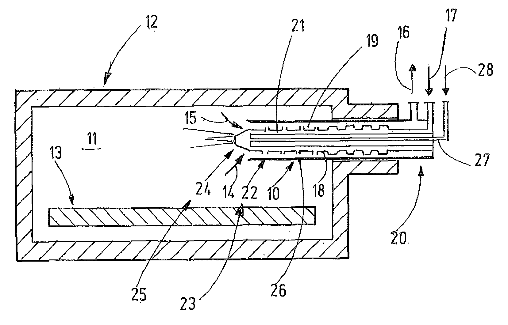
[0018] FIG. 1 a schematic sectional view of a furnace chamber with a burner according to the invention,
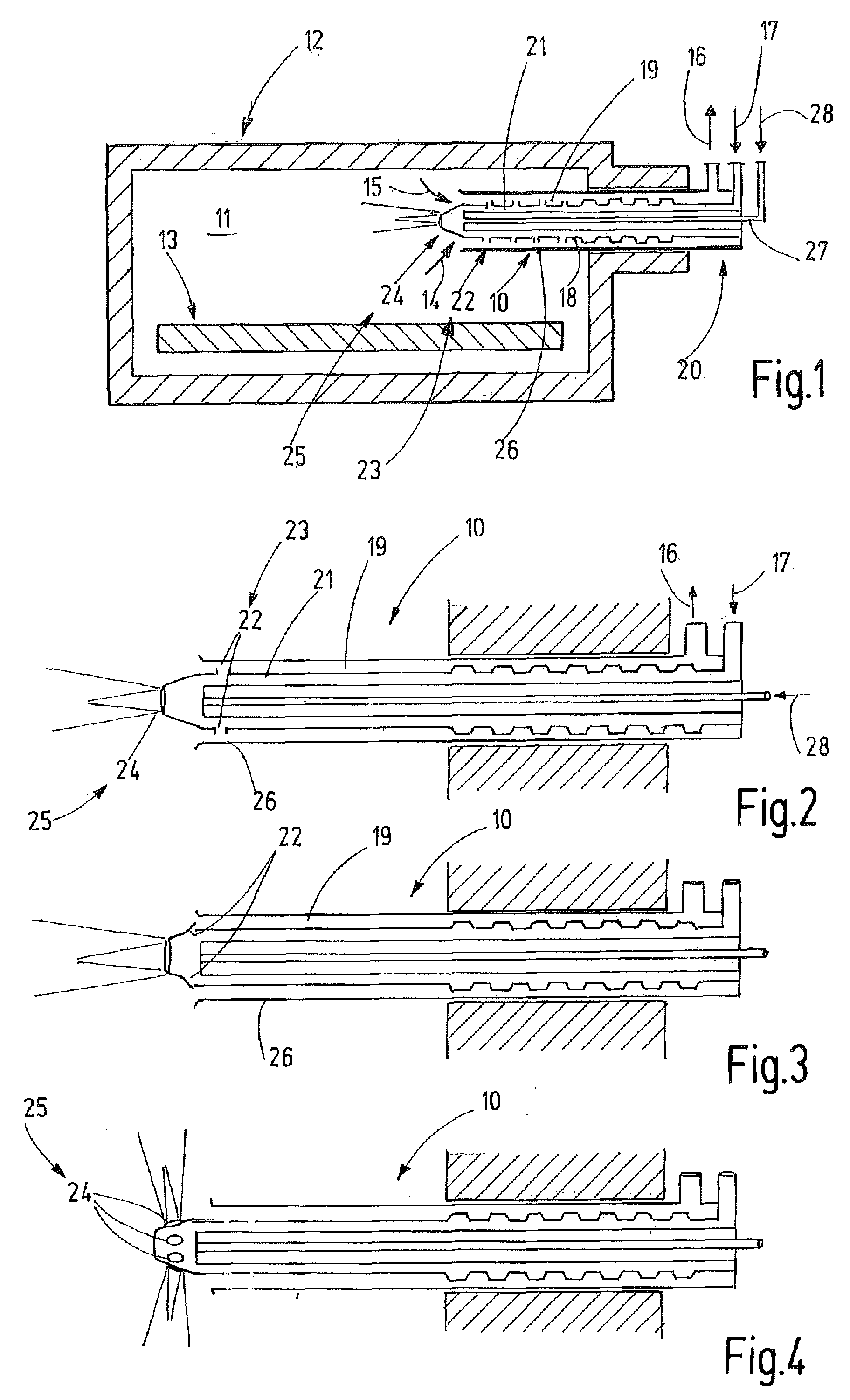
[0019] FIG. 2 a schematic sectional view of a modified embodiment of the burner according to the invention,
[0020] FIG. 3 a longitudinal sectional view of a further modified embodiment of the burner according to the invention, and
[0021] FIG. 4 an embodiment of the burner according to the invention with radial or oblique flame ejection.
[0022] FIG. 1 shows a recuperative burner 10 that is disposed for heating the furnace chamber 11 of a schematically illustrated industrial furnace 12. In order to heat the latter, it is possible to provide several burners with heat recovery features, e.g., recuperative burners that are preferably constructed and configured in the same manner as the recuperative burner 10 and that can be controlled together, individually or in groups.
[0023] The industrial furnace is disposed for the heat treatment of a material to be heated 13 that, for example, may be semi-finished or finished products of metal or other materials. For example, these may be steel components, copper components or the like. The furnace temperature typically is in the range of several 100.degree. C. and is consistent with the desired application. If the temperature is above a critical temperature of typically approximately 850.degree. C., the burner 10 can be operated with flameless oxidation. If the furnace temperature is below this limit, the burner 10 preferably is operated in a flame mode. This mode is also selected during the ramping up stage, in particularly in the event of a cold start. The cold start may take place with stoichiometric operation or superstoichiometric operation.
[0024] Preferably, the burner 10 is a so-called recuperative burner that is disposed to extract thermal energy from an exhaust gas stream indicated by arrows 14, 15 16, in order to thus supply a fresh air stream indicated by arrow 17 with heat. To accomplish this, the recuperative burner 10 comprises a recuperator 18 which is preferably configured as a profiled tube with closed walls and the outside of which delimits an exhaust gas channel 19.
[0025] The recuperator 18 may consist of metal, for example, or, as is preferred, of ceramic and be imparted on its outside with structures so as to enlarge the surface and provide an improvement of the heat exchange with the exhaust gas. Such structures may be elevations and/or recesses, spikes, burls or the like. The recuperator 18 extends concentrically to the longitudinal center axis of the recuperative burner 10 and, in so doing, is preferably held outside the furnace chamber 11 in a burner head 20. Appropriate holding means have been known from practical applications and are not specifically shown in FIG. 1.
[0026] Adjoining the actual recuperator 20 is a protrusion 21 that, likewise, preferably has a tubular shape. The protrusion 21 may be a direct integral component of the recuperator 18 and extend away from said recuperator in axial extension. This protrusion 21, too, may be disposed for recuperation (heat recovery). Preferably, the recuperator 18 extends through the furnace wall while the protrusion 21 preferably forms a part extending into the furnace chamber 11.
[0027] Preferably, the protrusion 21 may have one of the several openings that extend through its wall and lead from its interior space out into the exhaust channel 19. These openings 22 act as the air conducting device 23 for introducing burn-out air into the exhaust gas channel 19.
[0028] On its free end, the protrusion 21 is provided with at least one opening 24 that forms a burner orifice 25 and is arranged concentrically with respect to the burner axis. The openings 22, as well as the opening 24, are filled with fresh air that--as indicated by arrow 17--is introduced at the burner head 20 into the chamber of the recuperator 18 and leaves as burner air (primary air) at the opening 24 and as burn-out air (secondary air) at the openings 22.
[0029] The recuperator 18 and the protrusion 21 are enclosed by a tube 26 that extends through the furnace wall and projects into the chamber 11. Preferably, the tube 26 is arranged concentrically with respect to the recuperator 18 and the protrusion 21 and delimits the exhaust gas channel 19 in radially outward direction. Preferably, the protrusion 21 extends through the tube 26 so that the burner orifice 25 projects from the tube 26. The part of the tube 25 projecting into the furnace chamber 11 acts as the radiant tube. It is heated by the exhaust gas flowing in the exhaust gas channel 19 and by the post-combustion taking place therein, said post-combustion being maintained by the burn-out air supplied by the air conducting device 23. Preferably, the post-combustion is completed in the exhaust gas stream before the exhaust gas stream reaches the recuperator 18. The protrusion 21 may contribute as an ancillary function to the recuperation. This improves the energy yield of the burner 10.
[0030] A fuel supply line 27 extends centrally through the recuperator 18 and the protrusion 21, said fuel supply line having an open end directed at the burner orifice 25 and dispensing fuel through said orifice into the furnace chamber 11.
[0031] The recuperative burner 10 described so far operates as follows:
[0032] During operation, liquid or gaseous fuel is introduced into the burner--as indicated by arrow 28--via the fuel line 27. Furthermore, air (arrow 17) is introduced into the recuperator and exhaust gasses are evacuated through the exhaust gas channel 19 (arrows 14, 15, 16). During stationary operation, the exhaust gas flowing downstream through the exhaust gas channel 19 heat the protrusion 21 and the recuperator 18 which, in turn, heats inflowing air. A stream consisting of preheated air and fuel leaves the burner orifice 25, said stream--depending on the operating mode--either combusts with flame or oxidizes without flame due to a large-volume exhaust gas recirculation and a sufficient impulse of fresh air and fuel in the heated furnace chamber. Consequently, the burner 10 can be set up as specifically needed, either for flameless oxidation or for flame operation.
[0033] The supplied amount of fuel and the primary air amount flowing out through the opening 24 are adapted to each other in such a manner that a substoichiometric combustion results in the furnace chamber 11. For example, only 70% to 90%, preferably only 80%, of the air required for a complete combustion are dispensed at the opening 24, as a result of which a reducing furnace atmosphere is formed (.lamda.=0.8). This furnace atmosphere may contain fuel residues, partially combusted fuel and, in particular, also carbon monoxide. This exhaust gas--as indicated by arrows 14, 15--enters into the exhaust gas channel 19. Now, via the openings 22, the remaining 20% of the air required for the complete combustion are dispensed as burn-out air into the exhaust gas channel. The post-combustion taking place here heats the affected part of the tube 26 and then flows toward the recuperator 18.
[0034] The allocation of the air to the burner orifice 25 and the air conducting device 23 is preferably determined by the ratio of the cross-sections of the openings 24, 22 to one another. Consequently, the air allocation can be firmly specified at the time of manufacture of the recuperative burner 10. The recuperative burner 10 is preferably fired in pulsed mode or in continuous mode. Modulating mode is possible, however not necessary in most applications. Due to the pulsed operation, the recuperative burner 10 ultimately knows only three operating states, i.e., (a) ramping up mode, (b) heated mode, and (c) stoppage mode. During heated mode, the recuperative burner 10 is operated with the specified fuel and air supply and exhaust gas discharge. In so doing, it is ensured that the ratio between burner air and burn-out air is maintained as specified.
[0035] In modulated mode, it is possible that--due to different non-linear flow resistances of the openings 22 and 24--the ratio between the burner air (primary air) and the burn-out air (secondary air) shifts relative to full load in the event of partial load. This effect can also be consciously used in combination with pulsed mode in order to control the composition of the furnace atmosphere.
[0036] The recuperative burner 10 shown in FIG. 1 heats the material to be heated 13, partially directly by flame or flameless oxidation and partially indirectly by heat radiation from the tube 26. It combines high utilization of fuel due to heat recovery with careful heating of the material to be heated 13 by avoiding local heat peaks and by avoiding oxidative loading of the material to be heated, with good exhaust gas values.
[0037] FIG. 2 shows a modified embodiment of a recuperative burner 10, to which the description hereinabove applies analogously, while the same reference signs are being used. However, in contrast with the recuperative burner 10 described hereinabove, the air conducting device 23 is restricted to a few openings 22 that are provided in the vicinity of the front end of the protrusion 21. Consequently, the introduction of air into the exhaust gas channel 19 is restricted to the part of the (radiant) tube 26 that is close to the exhaust gas inlet. In so doing, the openings 22 can be oriented radially as indicated in FIGS. 1 and 2. The size of the openings 22 may be the same for all openings 22. Alternatively, the size of the openings 22 may also vary in axial direction of the protrusion 21 in one embodiment according to FIG. 1. For example, it may increase or decrease away from the burner orifice 25.
[0038] As is shown by FIG. 3 the openings 22 for the burn-out air may also be provided approximately at the level of the end of the radiant tube 26 and impart the leaving burn-out air flow with an axial component in addition to the radial component. In all embodiments, flame as well as flameless oxidation is possible in the exhaust gas channel 19.
[0039] As depicted by FIG. 4, the burner orifice 25 may also have several outlet openings 24; this may be of particular importance when their direction of exit is directed radially or obliquely relative to the axial line of the recuperative burner 10. Such a recuperative burner 10 can always be arranged suspended in a furnace chamber 12 according to FIG. 1, for example on the upper side of the furnace chamber, and still prevent the fuel stream from impinging on the material to be heated 13.
[0040] According to the invention a recuperative burner 10 is provided which fires a furnace chamber 11 in a substoichiometric manner. The recuperative burner is arranged in a radiant tube 26 which is open towards the furnace chamber and which protrudes into the furnace chamber. Together with the recuperator 18 or a protrusion 21, the radian tube 26 forms an exhaust gas channel 19 into which burn-out air is introduced by means of an air conducting device 23. The post-combustion which thus occurs in the exhaust gas channel 19 heats the radiant tube 26. The furnace chamber 11 is thus heated partly directly by fuel and air and partly indirectly by the radiant tube 26. An excessive level of CO emission is prevented by the post-combustion in the exhaust gas channel 19. By virtue of the use of the resulting heat by the radiant tube, excessively high exhaust gas temperatures are prevented and the thermal use of the fuel is optimized.
LIST OF REFERENCE SIGNS
TABLE-US-00001 [0041] 10 Burner/recuperative burner 11 Furnace chamber 12 Industrial furnace 13 Material to be heated (e.g., steel parts, copper parts, other metal parts or parts of nonmetallic material) 14-16 Arrows for exhaust gas 17 Arrows for fresh gas 18 Recuperator 19 Exhaust gas channel 20 Burner head 21 Protrusion 22 Opening(s) 23 Air conducting device 24 Opening 25 Burner orifice 26 Pipe (radiant tube) 27 Fuel line 28 Arrow
* * * * *
D00000
D00001
XML
uspto.report is an independent third-party trademark research tool that is not affiliated, endorsed, or sponsored by the United States Patent and Trademark Office (USPTO) or any other governmental organization. The information provided by uspto.report is based on publicly available data at the time of writing and is intended for informational purposes only.
While we strive to provide accurate and up-to-date information, we do not guarantee the accuracy, completeness, reliability, or suitability of the information displayed on this site. The use of this site is at your own risk. Any reliance you place on such information is therefore strictly at your own risk.
All official trademark data, including owner information, should be verified by visiting the official USPTO website at www.uspto.gov. This site is not intended to replace professional legal advice and should not be used as a substitute for consulting with a legal professional who is knowledgeable about trademark law.