Oil Flow Switch And Lubrication System With The Same For A Refrigeration System
Li; Jing ; et al.
U.S. patent application number 16/325685 was filed with the patent office on 2019-07-04 for oil flow switch and lubrication system with the same for a refrigeration system. The applicant listed for this patent is Johnson Controls Air Conditioning and Refrigeration (Wuxi) Co., Ltd., Johnson Controls Technology Company, York (Wuxi) Air Conditioning and Refrigeration Co., Ltd.. Invention is credited to Jing Li, Jinliang Li, Tianlong Xiao.
| Application Number | 20190203882 16/325685 |
| Document ID | / |
| Family ID | 59762057 |
| Filed Date | 2019-07-04 |


| United States Patent Application | 20190203882 |
| Kind Code | A1 |
| Li; Jing ; et al. | July 4, 2019 |
OIL FLOW SWITCH AND LUBRICATION SYSTEM WITH THE SAME FOR A REFRIGERATION SYSTEM
Abstract
The present disclosure relates to an oil flow switch, comprising a float device connected to a circulating oil passage and a floating liquid level switch element provided in the float device, wherein the float device comprises an oil inlet, an oil outlet, and a float chamber provided between the oil inlet and the oil outlet, the floating liquid level switch element is provided in the float chamber, and the float device is provided with a channel in communication with the float chamber. The oil flow switch according to the present disclosure may avoid a false alarm of the oil level switch and meanwhile mitigate disturbance to the float caused by liquid level fluctuation to reduce friction between the float and the sleeve rod. Further, a lubrication system with the above oil
| Inventors: | Li; Jing; (New Freedom, PA) ; Xiao; Tianlong; (Wuxi, CN) ; Li; Jinliang; (Wuxi, CN) | ||||||||||
| Applicant: |
|
||||||||||
|---|---|---|---|---|---|---|---|---|---|---|---|
| Family ID: | 59762057 | ||||||||||
| Appl. No.: | 16/325685 | ||||||||||
| Filed: | August 16, 2017 | ||||||||||
| PCT Filed: | August 16, 2017 | ||||||||||
| PCT NO: | PCT/US2017/047219 | ||||||||||
| 371 Date: | February 14, 2019 |
| Current U.S. Class: | 1/1 |
| Current CPC Class: | F16N 2280/00 20130101; F25B 31/004 20130101; F16N 7/40 20130101; F16N 2250/18 20130101; F25B 2700/03 20130101; F25B 2500/16 20130101; F16N 29/00 20130101; F25B 31/002 20130101; F16N 23/00 20130101; F16N 2210/10 20130101; F25B 43/003 20130101 |
| International Class: | F16N 23/00 20060101 F16N023/00; F16N 29/00 20060101 F16N029/00; F16N 7/40 20060101 F16N007/40; F25B 31/00 20060101 F25B031/00; F25B 43/00 20060101 F25B043/00 |
Foreign Application Data
| Date | Code | Application Number |
|---|---|---|
| Aug 17, 2016 | CN | 201610688055.5 |
| Aug 17, 2016 | CN | 201620903382.3 |
Claims
1. An oil flow switch, comprising a float device connected to a circulating oil passage and a floating liquid level switch element provided in the float device, wherein the float device comprises an oil inlet, an oil outlet, and a float chamber provided between the oil inlet and the oil outlet, the floating liquid level switch element is provided in the float chamber, and the float device is provided with a channel in communication with the float chamber.
2. The oil flow switch according to claim 1, wherein an oil flow hole is provided at a bottom of the oil inlet of the float device to make the float chamber filled with oil by means of an impulse of the oil flow or a local pressure drop caused by a change of flow direction of the oil flow.
3. The oil flow switch according to claim 1, wherein a channel for discharging gas in the float chamber is disposed between the float chamber and the oil outlet.
4. The oil flow switch according to claim 1, wherein the floating liquid level switch element further comprises a float switch base fixedly provided in the float chamber and a float movable relative to the float switch base with the rise and fall of a liquid level in the float chamber.
5. The oil flow switch according to claim 4, wherein the float switch base is fixedly threaded in the float chamber, and the float switch base is further provided with a sleeve rod on which the float ball is strung.
6. The oil flow switch according to claim 1, wherein the float chamber is also provided with a sight glass for observing a liquid level and a working state of the float.
7. The oil flow switch according to claim 1, wherein a reed switch triggered by the float is provided on the float switch base, and a digital signal generated by the reed switch is transmitted outward via a signal line on the float switch base.
8. The oil flow switch according to claim 1, wherein the float chamber and the float device are integrally formed into a single piece.
9. A lubrication system for a refrigeration system, wherein the lubrication system comprises a compressor, an oil storage device, an oil flow switch, a filter, and a circulating oil pump, all of which are connected through a circulation pipeline, the oil flow switch is provided downstream of the oil storage device, an oil inlet of the oil flow switch is in communication with an oil outlet of the oil storage device, and the circulating oil pump is configured for pumping filtered lubricant back into the compressor, characterized in that the oil flow switch is the oil flow switch according to any one of claims 1-8.
Description
FIELD OF THE INVENTION
[0001] The present disclosure generally relates to an oil lubrication technology, and more particularly to an oil flow switch and a lubrication system with the same for a refrigeration system.
BACKGROUND OF THE INVENTION
[0002] In a refrigeration system, refrigerant oil functions to lubricate, seal, and reduce noise, etc.; therefore, early warning about an oil level of lubricant is critical to ensure system reliability. A float level switch or a photoelectric level switch is commonly employed in current approaches for determining whether the oil level is lower than a predetermined oil level. Specifically, the float level switch is a mechanical liquid level switch in which a float will float under the buoyancy force in the liquid, and will sink once the liquid level is insufficient during which the magnetic field of a magnet built in the float will change, which consequently changes a state of a contact in a reed switch, i.e., changing from a previous off state to an on state, or vice versa, thereby signaling that the liquid level is lower than the predetermined oil level. The photoelectric liquid level switch is an electronic liquid level switch, and works following optical principles and electronic technologies, in which light emitted from a light-emitting diode will be refracted back by a prism in the presence of oil so that an electronic sensing part can receive the refracted light, i.e., indicating a normal oil level; once the oil level is lower than the prism, the light will be scattered in an oil sink and cannot be refracted back so that it may be sensed whether the oil level is normal or not. During use, once the liquid level in the oil sink or oil tank is lower than a liquid level of a amount of reserved oil, the liquid level switch will emit a low-oil-level signal; upon receiving the signal from the level switch, a controller will stop an equipment from running to protect the equipment from possible running with insufficient oil.
[0003] During use, it is found that both of the float level switch and the photoelectric level switch have a drawback: once bubbles exist in the liquid, neither of the switches can accurately sense whether the liquid level is proper. In a refrigeration system, a certain percentage of refrigerant is always dissolved in an oil solution such that upon a change of temperature or pressure, the refrigerant dissolved in the oil solution will possibly be evaporated with bubbles. This will cause a decrease in the density of the oil solution and a failure of the float of the float level switch to float, and consequently the level switch will emit a false level signal. Likewise, for the photoelectric liquid level switch, due to the effervescent oil solution, the light emitted from the photoelectric liquid level switch cannot be successfully refracted back from the prism to the photoelectric switch, which will also cause a false alarm.
SUMMARY OF THE INVENTION
[0004] One of the objectives of the present disclosure is to at least partially solve the above problems in the prior art by providing an oil flow switch and a lubrication system with the same for a refrigeration system.
[0005] According to an aspect of the present disclosure, there is provided an oil flow switch, comprising a float device connected to a circulating oil passage and a floating liquid level switch element provided in the float device, wherein the float device comprises an oil inlet, an oil outlet and a float chamber provided between the oil inlet and the oil outlet, the floating liquid level switch element is provided in the float chamber, and the float device is provided with a channel in communication with the float chamber.
[0006] According to the present disclosure, the oil flow switch may be provided on the circulating oil passage of a compressor. When oil flows through the oil flow switch, the float chamber will be filled with oil liquid. The float will overcome its own gravity and rise under a buoyancy force, and at this point, the oil flow switch is turned on. Meanwhile, once there is no oil passing through the oil passage, the oil in the float chamber will return to an oil pipe under the action of its gravity. At this point, the buoyancy force is lost gradually, and finally, the float falls back to a lower-limit position, and the oil flow switch is turned off. It is knowable that as long as oil flows in the circulating oil passage, the float chamber will be filled with oil liquid, and thus the oil flow switch will not be off. In this way, false alarms caused by various reasons may be effectively prevented.
[0007] Optionally, an oil flow hole may be provided at a bottom of the oil inlet of the float device to make the float chamber filled with oil by means of an impulse of the oil flow or a local pressure drop caused by a change of flow direction of the oil flow.
[0008] Optionally, a channel for discharging gas in the float chamber may be disposed between the float chamber and the oil outlet.
[0009] Optionally, the floating liquid level switch element may further comprise a float switch base fixedly provided in the float chamber and a float movable relative to the float switch base with the rise and fall of a liquid level in the float chamber.
[0010] Optionally, the float switch base may be fixedly threaded in the float chamber, and the float switch base may be further provided with a sleeve rod on which the float is strung.
[0011] Optionally, the float chamber may also be provided with a sight glass for observing a liquid level and a working state of the float.
[0012] Optionally, the float switch base may be provided with a reed switch which is triggered by the float and generates a digital signal transmitted outwards via a signal line on the float switch base.
[0013] Optionally, the float chamber and the float device may be integrally formed into a single piece.
[0014] According to another aspect of the disclosure, a lubrication system for a refrigeration system is disclosed, wherein the lubrication system may comprise a compressor, an oil storage device, an oil flow switch, a filter, and a circulating oil pump, all of which may be connected through a circulation pipeline, the oil flow switch may be provided downstream of the oil storage device, an oil inlet of the oil flow switch may be in communication with an oil outlet of the oil storage device, and the circulating oil pump is configured for pumping filtered lubricant back into the compressor, characterized in that the oil flow switch is an oil flow switch according to the present disclosure.
BRIEF DESCRIPTION OF THE DRAWINGS
[0015] The above and other aspects of the present disclosure will become more apparent and comprehensible through the descriptions of illustrative embodiments of the present disclosure with reference to the accompanying drawings, in which:
[0016] FIG. 1 schematically illustrates a general layout of a refrigeration system according to the present disclosure;
[0017] FIG. 2 schematically illustrates an embodiment of an oil flow switch connected to an oil passage;
[0018] FIG. 3 schematically illustrates another embodiment of the oil flow switch;
[0019] FIG. 4 schematically illustrates a further embodiment of the oil flow switch;
[0020] FIG. 5 schematically illustrates an oil flow switch connected to an oil storage tank.
EXPLANATIONS OF REFERENCE NUMERALS
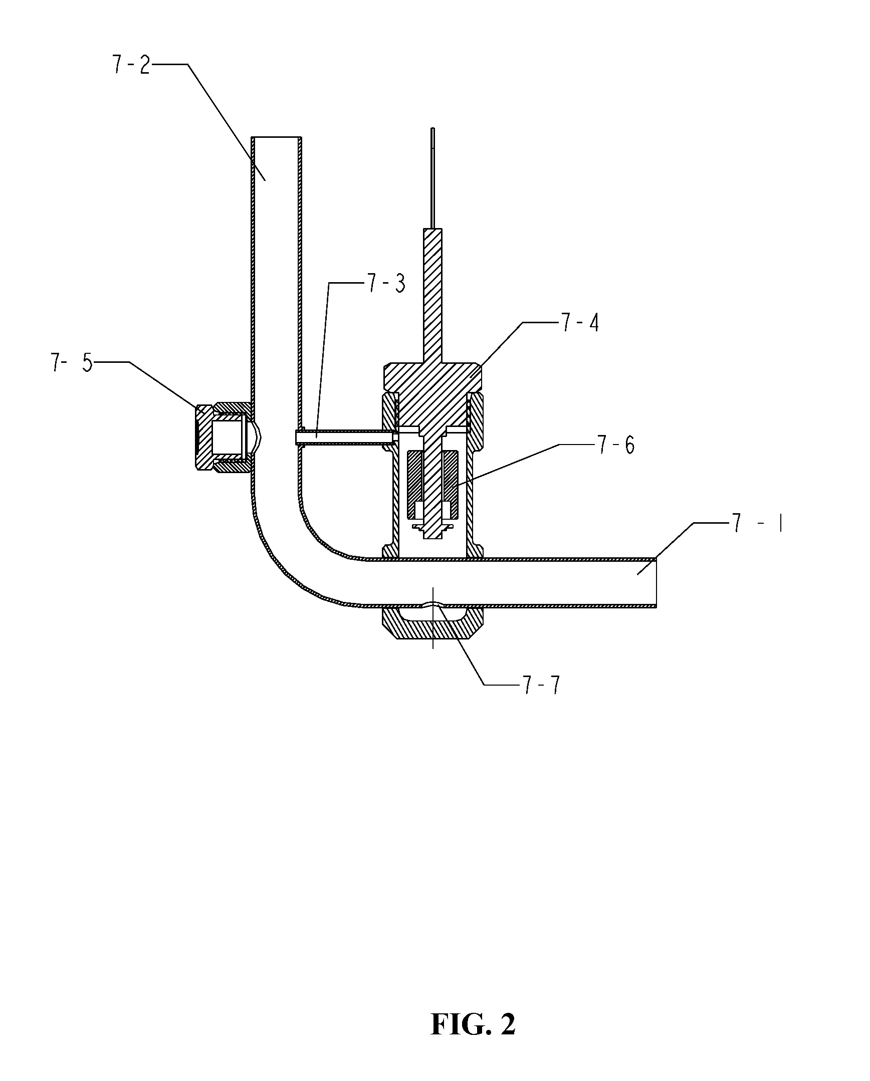
[0021] 1. compressor 2, 8. one-way valve 3. oil storage tank 5. filter 4, 9. angle valve 6. oil pump 7. float device 10. oil supply electromagnetic valve 7-1. oil inlet 7-2. oil outlet 7-3. channel 7-4. float switch 7-5. sight glass 7-6. float 7-7. oil flow hole
DETAILED DESCRIPTION OF THE EMBODIMENTS
[0022] Hereinafter, the preferred embodiments of the present disclosure will be described with reference to the accompanying drawings. It needs to be noted that the terms "upper," "lower," "front," "rear," "left," "right," and similar expressions used herein are only for illustration purposes, not intended for limiting.
[0023] FIGS. 1-2 illustrate a refrigeration system according to the present disclosure, wherein the refrigeration system may comprise a compressor 1 configured to compress a refrigerant for refrigeration circulation, wherein lubricant in the compressor 1, after being separated in an oil separator of the compressor 1, is guided to an oil storage tank 3 via a pipeline and a one-way valve 2, and then is in communication with an oil inlet 7-1 of the float device 7 via the pipeline. Further, the lubricant flows out of an oil outlet 7-2 of the float device 7 into an angle valve 4, and after being filtered by a filter 5, is guided into a one-way valve 8 or an oil pump 6 so that the filtered lubricant returns into the compressor 1 via an oil supply electromagnetic valve 10, thereby forming a circulating lubrication system of the refrigeration system.
[0024] During actual use, an oil level in the oil storage tank 3 needs to be monitored to ensure enough lubricant to be fed into the compressor 1. According to the present disclosure, monitoring the oil level in the oil storage tank 3 may be implemented by a float device 7 connected to a lubricant passage. As illustrated in FIG. 2, the float device 7 may have an oil inlet 7-1 connected to an oil outlet pipe of the oil storage tank 3 and an oil outlet 7-2 connected to an oil inlet pipe of the angle valve 4. The float device 7 may comprise a float chamber disposed on the pipeline and a float switch 7-4 fixedly threaded to the float chamber. Particularly, the float switch 7-4 may be integrally formed with a sleeve rod, and the float 7-6 may be strung on the sleeve rod to float up and down along the sleeve rod in the float chamber with respect to a liquid level state in the oil storage tank 3. Preferably, a reed switch triggered by the float may be provided on the float switch base. A digital signal generated by the reed switch may be transmitted outward via a signal line on the float switch base. Meanwhile, due to the lubricant, friction between the float 7-6 and the sleeve rod may also be reduced. A sight glass may be provided in the float chamber to observe a liquid level and a working state of the float. Preferably, a small-diameter channel 7-3 may be provided between the float chamber and the oil outlet 7-2. Due to a pressure difference existing between the inlet 7-1 and the outlet 7-2, under the action of the channel 7-3, gas in the top of the float chamber will be discharged so that the float chamber may be filled with liquid as much as possible. An oil flow hole 7-7 may be provided at a bottom of the oil inlet pipe of the float device 7 so that after the lubricant enters from the oil inlet 7-1, the float chamber will be filled with lubricant due to an impulse of the oil flow or a local pressure drop generated by an elbow, and meanwhile such a structure will make the oil level switch 7-4 shorter to provide a better stability.
[0025] Referring to FIG. 5, FIG. 5 illustrates a float device 7 connected to an oil storage tank 3. As illustrated in the figure, a mounting height h of the float device 7 may be adjusted as needed, mainly depending on the amount of the reserved lubricant in the oil storage tank 3. For different models of compressors, the amount of the reserved lubricant may be different, depending on applications in different systems. Therefore, a height position where the float is closed may be allowed to be flush with a reserved liquid surface of the lubricant in the oil tank 3 by adjusting the mounting height h of the float device 7. Particularly, the reserved liquid surface of the lubricant refers to a minimum amount of lubricant that may still guarantee a normal start of the compressor and recovery of the lubricant into the oil storage tank 3 when a low-oil-level warning presents.
[0026] During operation, the lubricant discharged from the compressor 1 flows in a circulating oil passage under the action of the oil pump 6. When the lubricant from the oil storage tank 3 flows through the float device 7, the float chamber will be filled with the lubricant such that the float 7-6 can overcome the gravity to rise under the action of buoyancy force to keep the oil flow switch always in an on state. Once there is no oil passing through the oil pipe, the oil in the float chamber will return to the oil pipe under the action of its own gravity. At this point, the buoyancy force of the float 7-6 will be gradually lost, and finally the float 7-6 will fall to a lower limit position where the oil flow switch becomes off. It is knowable that with the oil flow switch according to the present disclosure, as long as oil is flowing in the lubricant passage, the float chamber will be filled with the oil liquid, and thus an off state of the oil flow switch will not occur so that a false alarm caused by various reasons may be effectively prevented.
[0027] FIG. 3 illustrates another embodiment of an oil flow switch according to the present disclosure. Particularly, the float chamber and the float device may be integrally formed into a single piece, wherein the float chamber is disposed on the oil pipeline side of the float device, and communicated with the oil inlet 7-1 of the oil pipeline via the oil flow hole 7-7. The float switch may be fixedly mounted to the float chamber for example through a threaded connection, and a sight glass 7-5 for observing a liquid level may be provided on one side of the float chamber. The float chamber and the oil outlet 7-2 of the oil pipeline may be connected via the channel 7-3 such that the air in the float chamber can be discharged. According to a preferred embodiment of the present disclosure, integration of the components may be realized so that the float device can be easily fitted into the circulating oil passage.
[0028] FIG. 4 illustrates a further embodiment of the oil flow switch according to the present disclosure. Particularly, the float chamber and the float device may be integrally formed into a single piece, wherein the float chamber may be provided on one side of the oil pipeline of the float device, and the float chamber may be communicated with the oil inlet 7-1 of the oil pipeline via the oil flow hole 7-7. The float switch may be fixedly mounted to the float chamber for example through a threaded connection, and a sight glass 7-5 for observing a liquid level may be provided on one side of the float chamber. According to a preferred embodiment of the present disclosure, integration of the components may also be realized so that the float device can be easily fitted to the circulating oil passage.
[0029] The present invention has been described through the embodiments above. However, it should be understood that the above-described embodiments are only for exemplary and illustrative purposes rather than any intention to limit the present disclosure within the scope of the described embodiments. Besides, those skilled in the art may understand that the present disclosure is not limited to the embodiments above, and more alterations and modifications may be made according to the teaching of the present disclosure, and these alterations and modifications all fall within the claimed scope of the present disclosure.
* * * * *
D00000
D00001
D00002
D00003
D00004
D00005
XML
uspto.report is an independent third-party trademark research tool that is not affiliated, endorsed, or sponsored by the United States Patent and Trademark Office (USPTO) or any other governmental organization. The information provided by uspto.report is based on publicly available data at the time of writing and is intended for informational purposes only.
While we strive to provide accurate and up-to-date information, we do not guarantee the accuracy, completeness, reliability, or suitability of the information displayed on this site. The use of this site is at your own risk. Any reliance you place on such information is therefore strictly at your own risk.
All official trademark data, including owner information, should be verified by visiting the official USPTO website at www.uspto.gov. This site is not intended to replace professional legal advice and should not be used as a substitute for consulting with a legal professional who is knowledgeable about trademark law.