Oil Supply System For An Internal Combustion Engine
FOERSTER; Michael ; et al.
U.S. patent application number 15/737603 was filed with the patent office on 2019-07-04 for oil supply system for an internal combustion engine. The applicant listed for this patent is GE Jenbacher GmbH & Co. OG. Invention is credited to Michael FOERSTER, Alfred Herbert RANGGER.
| Application Number | 20190203618 15/737603 |
| Document ID | / |
| Family ID | 56463961 |
| Filed Date | 2019-07-04 |
| United States Patent Application | 20190203618 |
| Kind Code | A1 |
| FOERSTER; Michael ; et al. | July 4, 2019 |
OIL SUPPLY SYSTEM FOR AN INTERNAL COMBUSTION ENGINE
Abstract
Oil supply system for an internal combustion engine (1), whereby an internal oil pan (2) is arranged in the internal combustion engine (1), whereby the oil supply system has an additional external oil reservoir (3) which is arranged outside the internal combustion engine compared to the internal oil pan (2) of the internal combustion engine (1), whereby a supply line (4) to be connected to the internal combustion engine (1) is provided, which leads to a filling opening (5) of the oil reservoir (3), and whereby a return line (6) to be connected to the internal combustion engine (1) is provided, through which oil (0) can be returned from the oil reservoir (3) to the internal combustion engine (1), whereby the return line (6) is connected to the oil reservoir (3) and whereby the oil reservoir (3) has at least one oil tank (7), whereby a removal opening (8) of the return line (6) is arranged near or in the base of the at least one oil tank (7).
| Inventors: | FOERSTER; Michael; (Gablingen, DE) ; RANGGER; Alfred Herbert; (Kramsach, AT) | ||||||||||
| Applicant: |
|
||||||||||
|---|---|---|---|---|---|---|---|---|---|---|---|
| Family ID: | 56463961 | ||||||||||
| Appl. No.: | 15/737603 | ||||||||||
| Filed: | June 20, 2016 | ||||||||||
| PCT Filed: | June 20, 2016 | ||||||||||
| PCT NO: | PCT/AT2016/050213 | ||||||||||
| 371 Date: | December 18, 2017 |
| Current U.S. Class: | 1/1 |
| Current CPC Class: | F01M 2011/0095 20130101; F01M 11/0458 20130101; F01M 11/04 20130101; F01M 2011/0466 20130101; F01M 11/061 20130101 |
| International Class: | F01M 11/06 20060101 F01M011/06; F01M 11/04 20060101 F01M011/04 |
Foreign Application Data
| Date | Code | Application Number |
|---|---|---|
| Jun 25, 2015 | AT | A50551/2015 |
Claims
1. Oil supply system for an internal combustion engine (1), whereby an internal oil pan (2) is arranged in the internal combustion engine (1), whereby the oil supply system has an additional external oil reservoir (3) which is arranged outside the internal combustion engine compared to the internal oil pan (2) of the internal combustion engine (1), whereby a supply line (4) to be connected to the internal combustion engine (1) is provided, which leads to a filling opening (5) of the oil reservoir (3), and whereby a return line (6) to be connected to the internal combustion engine (1) is provided, through which oil (0) can be returned from the oil reservoir (3) to the internal combustion engine (1), whereby the return line (6) is connected to the oil reservoir (3) and whereby the oil reservoir (3) has at least one oil tank (7), whereby a removal opening (8) of the return line (6) is arranged near or in the base of the at least one oil tank (7).
2. Oil supply system according to claim 1, whereby the return line (6) is connected to a removal line (9) which extends to near the base of the at least one oil tank (7), whereby the removal line (9) has a removal opening (8) near the base of the at least one oil tank (7).
3. Oil supply system according to claim 1 or 2, whereby the supply line (4) opens near the at least one oil tank (7).
4. Oil supply system according to at least one of the preceding claims, whereby at least one flow guide device (15) is provided in the at least one oil tank (7).
5. Oil supply system according to at least one of the preceding claims, whereby a vent line (16) is provided, which connects the oil reservoir (3) to the return line (6). 282561
6. Oil supply system according to at least one of the preceding claims, whereby the removal line (9) has at least one vent hole (17) near the cover of the oil tank (7).
7. Oil supply system according to at least one of the preceding claims, whereby a preferably spring-loaded non-return valve (18) is provided in the supply line (4) between the internal combustion engine (1) and the oil reservoir (3).
8. Oil supply system according to at least one of the preceding claims, whereby at least two serially arranged oil tanks (7) are provided, whereby, in a first oil tank (7), the supply line (4) opens and the at least two oil tanks (7) are connected via at least one connecting line (19).
9. Oil supply system according to claim 8, whereby the return line (6) is connected to at least the second oil tank (7).
10. Oil supply system according to at least one of claims 1 to 6, whereby the return line (6) is connected to the at least one oil tank (7).
Description
[0001] The invention relates to an oil supply system for an internal combustion engine with the features of the preamble of claim 1.
[0002] In the case of oil supply systems for internal combustion engines known from the prior art, in a forced-feed lubrication, oil from an internal oil pan of the internal combustion engine is pumped to the consumers by an oil pump and is returned to the internal oil pan of the internal combustion engine under the influence of the gravity. It is also known that an oil level can be increased by increasing the oil volume involved in the circulation. For this purpose, for example, the internal oil pan of the internal combustion engine is connected to an additional oil reservoir, e.g. in the form of oil tanks.
[0003] However, in the operation of available oil supply systems with additional oil tanks, it has been found that oil taken via extracting lines from additional oil tanks often has only experienced a short dwell time in the additional oil tank prior to removal.
[0004] The object of this invention is therefore to provide an oil supply system with which the residence time of the oil in the additional oil reservoir is extended.
[0005] This object is achieved by an oil supply system with the features of claim 1. Advantageous developments are indicated in the dependent claims.
[0006] By placing a removal opening of the return line near the base or in the base of the at least one oil tank, a better mixing of the oil in the additional oil tank and a prolonged dwell time in the additional oil tank prior to removal are provided. This ensures that unused (fresh) oil is removed via the return line.
[0007] It is preferably provided that the return line is connected to a removal line which extends to the base of the at least one oil tank, whereby the removal line has a removal opening near the base of the at least one oil tank. This describes the case where the removal of oil from the oil tank is performed by means of a separate removal line extending into the oil tank. Alternatively, it can be provided that the removal is performed through an opening in the base of the oil tank. However, due to the accumulation of deposits in the base of the oil tank, it is preferable to perform a removal via a removal line extending to the base of the at least one oil tank.
[0008] It is preferably provided that the supply line opens near the base of the at least one oil tank. This measure results in a favorable flow through and mixing of the oil tank, since the oil originating from the internal combustion engine enters at high temperature and charged with gas. Thus, it has the tendency to ascend in the oil tank. When the supply line opens near the base of the at least one oil tank, the ascending oil causes the circulation of the oil volume in the oil tank.
[0009] It may be provided that at least one flow guide device is provided in the at least one oil tank. This measure further improves the throughflow in the oil tank. The flow guide device can be designed e.g. in the form of guide plates.
[0010] It is preferably provided that a vent line is provided which connects the oil reservoir to a return line. This measure makes it possible to remove the gases dissolved in the oil originating from the internal combustion engine from the oil tank. This measure is important, because otherwise the pressure in the oil tank may increase and thus the oil tank may be partly emptied into the oil pan. The venting can now take place such that a vent line is connected to a return line near the cover of the oil tank. In this case, the gases, together with the recycled oil for the return line, are introduced into a crankcase of the internal combustion engine.
[0011] It can be provided that the removal line has at least one venting hole near the cover of the oil tank. This additional or alternative venting measure ensures that no gases are collected in the oil tank, and that they are removed from the oil tank via the removal line.
[0012] It is preferably provided that a preferably spring-loaded non-return valve is installed in the supply line between the internal combustion engine and the oil reservoir.
[0013] A non-return valve prevents the oil from the oil lines of the internal combustion engine or oil from the oil pan from being emptied into the oil reservoir when the internal combustion engine is at a standstill. In general, the internal combustion engine and the external oil reservoir arranged outside the internal combustion engine are set up on the same structural level.
[0014] It may be provided that at least two serially arranged oil tanks are present, whereby the feed line opens into a first oil tank and the at least two oil tanks are connected via connecting lines. This describes the case in which the external oil reservoir is implemented in the form of a plurality of series-arranged oil tanks. In the case of the connection line between individual oil tanks, the measure is also taken that the removal opening of the connecting line is located near the base of the upstream oil tank. The return line to the internal combustion engine is then connected to at least the second oil tank.
[0015] If only one oil tank is provided, the return line is connected to the at least one oil tank.
[0016] The invention is particularly suitable for stationary internal combustion engines, in particular with a generator to internal combustion engines coupled to a genset.
[0017] The invention is particularly suitable for applications of internal combustion engines with high oil wear, e.g. in the case of power-boosting engines with unchanged oil volume, in biogas or landfill gas applications, or engines with small internal oil pans due to their construction.
[0018] The invention has proven to be particularly favorable in connection with the use of steel pistons.
[0019] The invention is explained in more detail with reference to the figures.
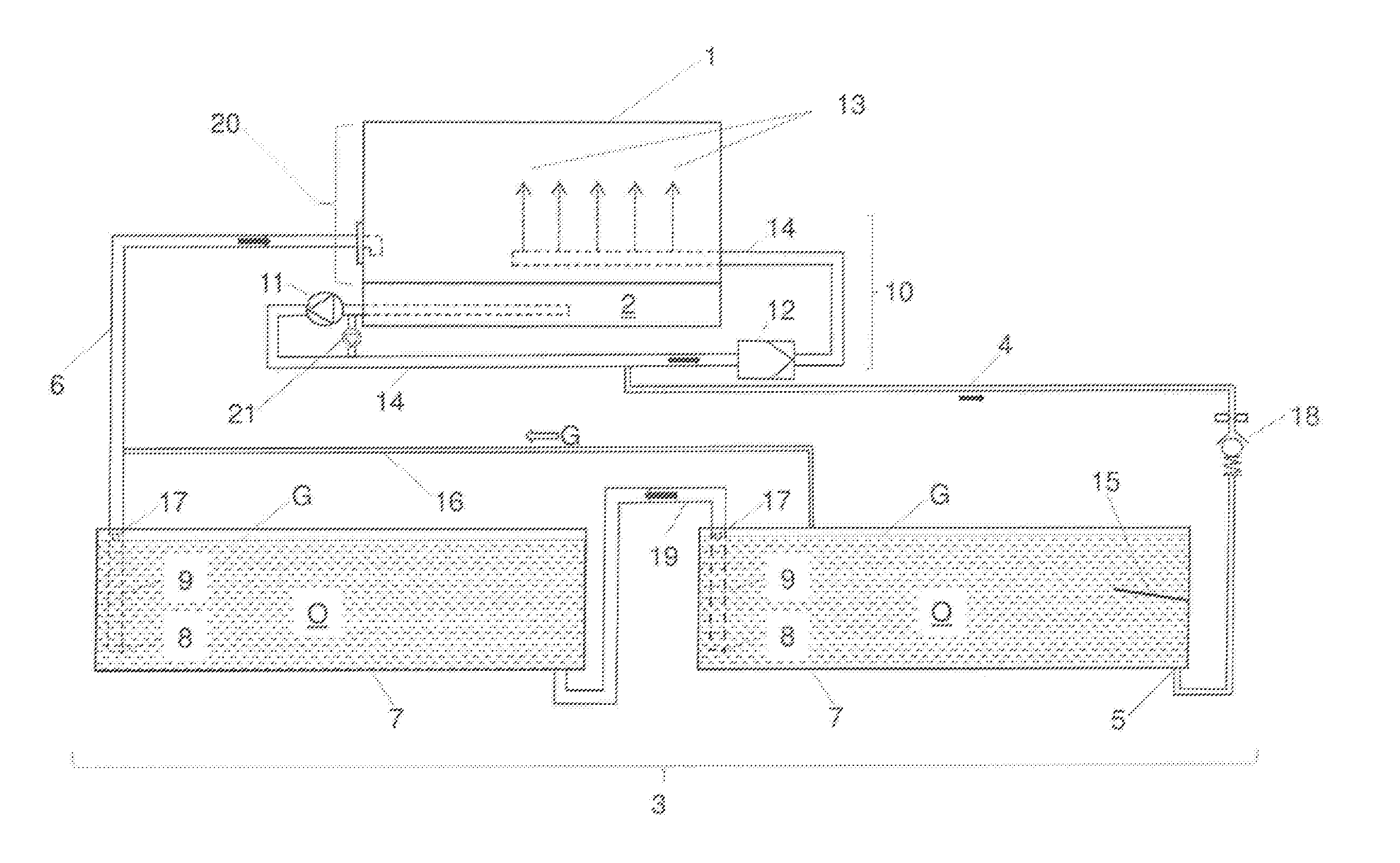
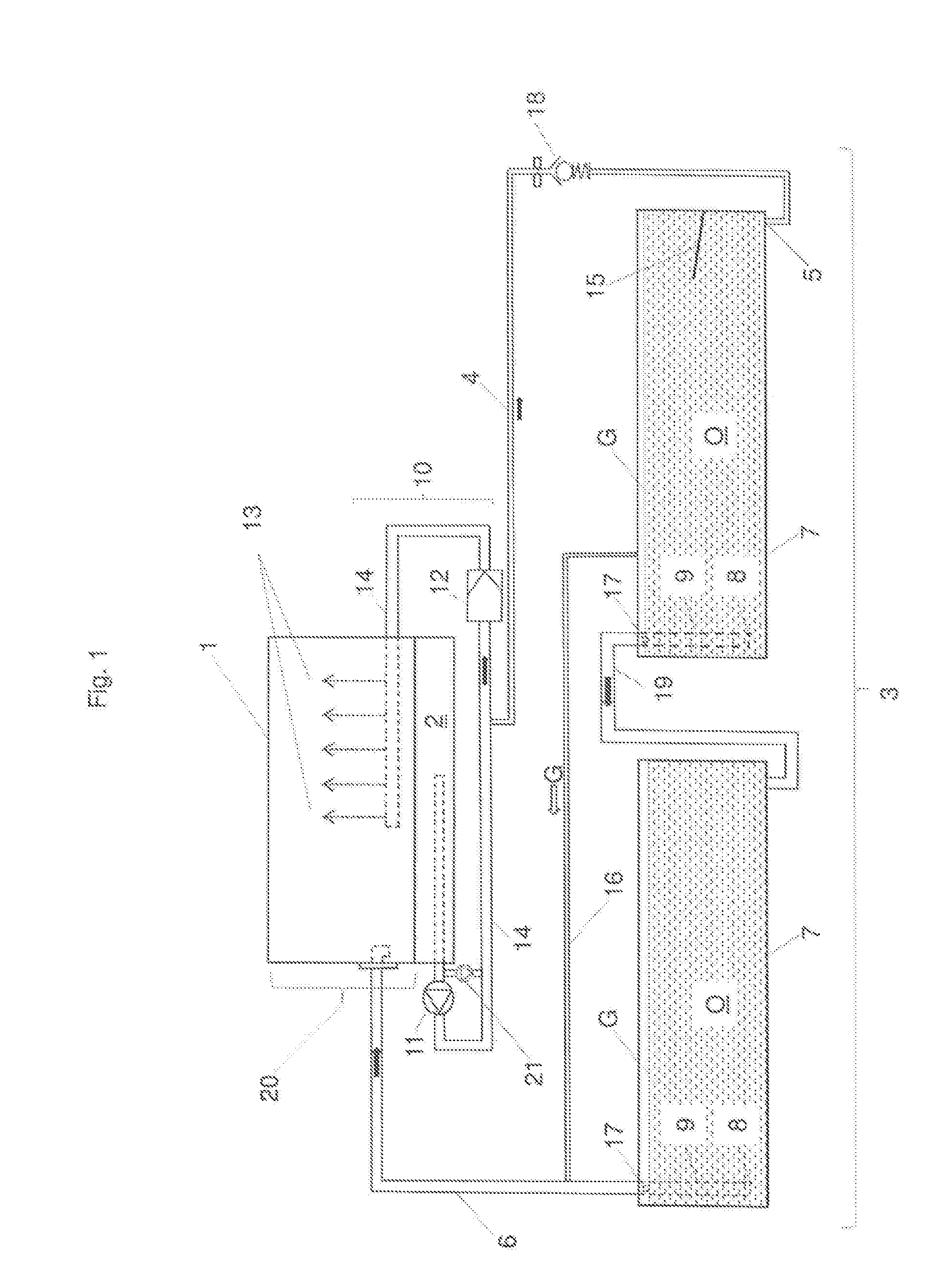
[0020] FIG. 1 shows an exemplary embodiment of an oil supply system according to the invention. It shows an internal combustion engine 1 with an internal oil pan 2. The oil supply system shown has a forced-feed lubrication 10.
[0021] In this simplified illustration, the forced-feed lubrication 10 comprises the oil pan 2, an oil pump 11, a main oil line 14 and an oil filter 12. The oil O is fed via the main oil line 14 to the consumers 13 in the internal combustion engine 1.
[0022] In the exemplary embodiment shown, a supply line 4 branches off from the main oil line 14 upstream of the oil filter 12 and feeds a partial flow of oil O into an external oil reservoir 3, in this case formed by two serially arranged oil tanks 7.
[0023] The oil reservoir 3 can, of course, also be formed of only a single oil tank 7. The oil level of the oil O in the two oil tanks 7 is indicated by the shaded area. Preferably, the oil level reaches as far as the lid of the oil tank 7.
[0024] From the second oil tank 7 located downstream of the first oil tank 7, the oil O is fed back to the internal combustion engine 1 via a return line 6.
[0025] In the exemplary embodiment shown, the supply line 4 leads to the first of the two series-arranged oil tanks 7 and opens into a filling opening 5 near the base of the oil tank 7.
[0026] A flow guide device 15, here in the form of a guide plate, can be provided to further improve the throughflow of the oil tank 7.
[0027] In the exemplary embodiment shown of two series-connected oil tanks 7, a connecting line 19 is provided between the oil tanks 7. In this case, a first removal line 9 leads via the connecting line 19 into the downstream oil tank 7. The removal opening 8 of the removal line 9 opening into the connection line 19 is arranged near the base of the oil tank 7.
[0028] If only one oil tank 7 is provided, the connecting line 19 is not included and the removal line 9 is connected directly to the return line 6.
[0029] The removal opening 8 of the removal line 9 is arranged near the base of the oil tank 7.
[0030] This results in favorable mixing of the oil O in the additional oil tank 7 (or the additional oil tank 7) and a prolonged dwell time of the oil O in the additional oil tank 7 before it is removed again and returned to the internal combustion engine 1. Thus, fresh oil O is always taken out of the oil tank 7 or the oil tank 7 via the removal opening 8.
[0031] Although not shown here, it is also conceivable for the removal opening 8 to be designed as an opening in the base of the oil tank 7, where it opens into the return line 6.
[0032] The oil O, charged with gas, enters the oil tank 7 from the internal combustion engine 1 at elevated temperature via the feed line 4 and the filling opening 5. The hot oil O ascends in the oil tank 7 to the surface. By the arrangement of the removal opening 8 near the base of the oil tank 7, on the one hand, good mixing of the oil O in the oil tank 7 is ensured, and on the other hand, it is ensured that non-hot oil just emerging from the internal combustion engine 1 is removed and fed back to the internal combustion engine 1.
[0033] The gas G dissolved in the oil O is separated from the oil O in the oil tank 7 and ascends to the surface. So that the pressure in the oil tank 7 does not rise, a vent line 16 is provided, which feeds the gas G to the return line 6. In this way, it passes again into a crankcase 20 of the internal combustion engine 1. Alternatively or additionally, it can be provided that the removal line 9 has a venting hole 17, via which the gas G can enter the return line 6 (or, in the case of several oil tanks, first into the connecting line 19).
[0034] The return line 6 opens into the crankcase 20 of the internal combustion engine 1, preferably above the oil level of the oil O in the oil pan 2.
[0035] In general, the internal combustion engine 1 and the external oil reservoir 3 arranged outside the internal combustion engine 1are set up on the same structural level. It may be the case that when the internal combustion engine 1 and the oil reservoir 3 are installed, the oil pan 2 rises above a reference level in the oil tank 7. This can lead to a leakage of oil O from the oil lines in the internal combustion engine 1 or a leakage of oil O from the oil pan 2 into the oil tank 7. A leakage from the oil lines when the internal combustion engine 1 is at a standstill, e.g. lines between the main oil line 14 and the consumers 13, is particularly unfavorable, because a pre-lubrication process is thus significantly prolonged before the internal combustion engine 1is started. In a pre-lubrication process, oil O is supplied to the consumers 13 before starting the internal combustion engine 1. The pre-lubrication is usually performed by a pre-lubrication pump 21, which is designed to perform well under the oil pump 11 and bridges it during the pre-lubrication process. The pre-lubrication pump 21 provides e.g. 0.8 bar of oil pressure.
[0036] A preferably spring-loaded non-return valve 18 prevents the oil O from the oil lines and oil pan 2 from being emptied into the oil reservoir 3 when the internal combustion engine 1 is at a standstill. A further particular advantage of a spring-loaded non-return valve 18 is that it remains closed in the pre-lubrication process, and thus the oil O in the pre-lubrication process only needs to be pumped through the internal combustion engine 1 and not through the entire oil reservoir 3.
[0037] The situation will be shown by means of a numerical example:
[0038] The external oil reservoir 3 is supplied with oil O by the supply line 4 via the main oil line 14. Upstream of the oil filter 12 with a pressure of 3 to 10 bar, a cross-sectional taper of the supply line 4 versus the main oil line 14 to a cross-section of 2.5 mm produces an oil flow of 6 l/min at an oil pressure of 4.2 bar at the removal point in the supply line 4. The circulation capacity of the oil pump 11 is 480 l/min. The temperature of the oil O emerging from the oil pan 2 is around 70.degree. C. The pre-lubrication pump 21 provides e.g. 0.8 bar of oil pressure. The opening pressure of the non-return valve 18 is designed to be e.g. 1 bar.
[0039] The pressure of the pre-lubrication pump 21 is then below the opening pressure of the non-return valve 18.
[0040] The oil reservoir 3 has approximately the same oil volume as the oil pan 2. The oil volume involved in the oil circulation is thus doubled by the oil reservoir 3.
LIST OF REFERENCE SIGNS
[0041] 1 Internal combustion engine
[0042] 2 Internal oil pan
[0043] 3 External oil reservoir
[0044] 4 Supply line
[0045] 5 Filling opening
[0046] 6 Return line
[0047] 7 Oil tank
[0048] 8 Removal opening
[0049] 9 Removal line
[0050] 10 Pressure circulation lubrication
[0051] 11 Oil pump
[0052] 12 Oil filter
[0053] 13 Consumers
[0054] 14 Main oil line
[0055] 15 Flow guide device
[0056] 16 Vent line
[0057] 17 Vent hole
[0058] 18 Non-return valve
[0059] 19 Connecting line
[0060] 20 Crankcase
[0061] 21 Pre-lubrication pump
[0062] O Oil
[0063] G Gas 282561 CLAIMS
* * * * *
D00000
D00001
XML
uspto.report is an independent third-party trademark research tool that is not affiliated, endorsed, or sponsored by the United States Patent and Trademark Office (USPTO) or any other governmental organization. The information provided by uspto.report is based on publicly available data at the time of writing and is intended for informational purposes only.
While we strive to provide accurate and up-to-date information, we do not guarantee the accuracy, completeness, reliability, or suitability of the information displayed on this site. The use of this site is at your own risk. Any reliance you place on such information is therefore strictly at your own risk.
All official trademark data, including owner information, should be verified by visiting the official USPTO website at www.uspto.gov. This site is not intended to replace professional legal advice and should not be used as a substitute for consulting with a legal professional who is knowledgeable about trademark law.