Variable High Pressure Transition Tube Set Point Adapter
Atencio; Don
U.S. patent application number 16/297432 was filed with the patent office on 2019-07-04 for variable high pressure transition tube set point adapter. The applicant listed for this patent is Don Atencio. Invention is credited to Don Atencio.
| Application Number | 20190203562 16/297432 |
| Document ID | / |
| Family ID | 52776038 |
| Filed Date | 2019-07-04 |


| United States Patent Application | 20190203562 |
| Kind Code | A1 |
| Atencio; Don | July 4, 2019 |
Variable High Pressure Transition Tube Set Point Adapter
Abstract
An apparatus, method, and system for inserting and securing a high pressure transition tube of a fluid transfer tool assembly into a positive position whereby the seal element is packed off in the wellhead set point. Once attached the transition tube is pushed to contact the bit guide, secondary seal or bore machine prep. A lower nose compression seal is seated against transition tube and compressed using an energizer seal to isolate and protect lower pressure wellhead and well control equipment from the higher rated frack pressures or pushing the transition tube and lower nose isolation compression seal to contact the bit guide, secondary seal or bore prep. Pressure is applied to push a seal against the lower and upper compression ring locking them in place preventing movement to form a compression seal and isolating the high pressure passing through the transition tube protecting the wellhead assembly and well control equipment.
| Inventors: | Atencio; Don; (Spring, TX) | ||||||||||
| Applicant: |
|
||||||||||
|---|---|---|---|---|---|---|---|---|---|---|---|
| Family ID: | 52776038 | ||||||||||
| Appl. No.: | 16/297432 | ||||||||||
| Filed: | March 8, 2019 |
Related U.S. Patent Documents
| Application Number | Filing Date | Patent Number | ||
|---|---|---|---|---|
| 14504556 | Oct 2, 2014 | |||
| 16297432 | ||||
| 61886192 | Oct 3, 2013 | |||
| Current U.S. Class: | 1/1 |
| Current CPC Class: | E21B 33/068 20130101; E21B 34/02 20130101 |
| International Class: | E21B 34/02 20060101 E21B034/02; E21B 33/068 20060101 E21B033/068 |
Claims
1. A stimulation tool comprising: a unibody master housing; a high pressure variable transition tube; a compression seal assembly comprising: an upper energizer ring, said upper energizer ring having a variable diameter; and a compression seal; said stimulation tool configured to engage a wellhead via said compression seal assembly when a downward force is applied to said high pressure variable transition tube; said high pressure variable transition tube comprising a structure to contain high pressure fluids from wellhead control equipment and transfer the high pressure fluids to well casing or production tubing; a safety locking ring; and a variable adjuster locking sleeve comprising at least one adjuster sleeve test port and at least a double barrier pressure seal configured to seal around said high pressure variable transition tube.
Description
CROSS-REFERENCE TO RELATED APPLICATIONS
[0001] This application is a continuation application of U.S. patent application Ser. No. 14/504,556, filed Oct. 2, 2014, which itself claims priority to and the benefit of the filing of U.S. Provisional Application No. 61/886,192 filed Oct. 3, 2013, and the specifications and claims, if any, thereof are incorporated herein by reference.
BACKGROUND OF THE INVENTION
Field of the Invention (Technical Field)
[0002] The presently claimed invention relates to oil and gas drilling systems, and more particularly to systems for insertion tools, for inserting and securing a high-pressure transition tube of a fluid/gas, and a transfer tool apparatus assembly into a positive position in which the seal element is packed off in the wellhead set point. The claimed invention is for the process of fracking, a method developed and used to crack open the formation at high pressures and to help the stimulations of oil and gas well production, and a tool, apparatus, and a configuration equipment and method for protecting frack containment and control equipment and wellhead from exposure to pressures higher than the pre-design operating range and from the abrasive and or corrosive fluids during well fracturing and pumping procedures.
Background Art
[0003] Wells require some form of stimulation called fracking to stimulate production and make or keep them productive. The fracking of oil and gas wells formations to stimulate production requires that high pressure pumping equipment be used to inject fluids, chemicals, and sands at high pressures. The frack fluids are generally corrosive and abrasive because of acids and abrasives used to open cracks in the formations with special sand.
[0004] New technology and methods as well as safety and environmental regulations that are being adopted industry wide cannot be accomplished with the lower pressure frack containment equipment, Blowout Preventers (BOPs) or through a valve attached to the wellhead. The practice of fracking or pumping through BOPs equipment, valves or wellheads at pressures higher that the pre-engineered design pressure rating has been determined to be unsafe and is no longer Standard Operating Practice (SOP).
[0005] This method was adopted because it was the only way to have full access to a well casing bore with down-hole tools during the well fracking or servicing. The industry's known methods and technologies indicate that new methods must be developed to acquire full bore access to well bore at much higher pressures. Full bore access to the casing permits use of down-hole tools that are often required during a frack stimulation treatment without having to remove tools or equipment between multi-stage frack stimulation, as was required with older style conventional wellhead isolation tools such as disclosed in U.S. Pat. No. 4,867,243, entitled WELLHEAD ISOLATION TOOL AND SETTING AND METHOD OF USING SAME.
[0006] An apparatus for providing full access to the casing while permitting stimulation treatments at extreme pressures that approach a burst pressure rating of the casing is described in U.S. Pat. No. 6,289,993, entitled BLOWOUT PREVENTER PROTECTION AND SETTING TOOL.
[0007] Another prior art reference describes an apparatus and method of isolating a well tree located on an oil or gas well from the effects of high pressure or corrosion caused by stimulation of a well is described in U.S. Pat. No. 4,867,243 entitled WELLHEAD ISOLATION TOOL AND SETTING TOOL AND METHOD OF USING SAME. This reference describes an apparatus to permit the injection of fluids, gases, solid particles, or mixtures through a well tree while protecting the well tree during well stimulation treatments. The apparatus includes a single hydraulic cylinder supported in an axial alignment over a well tree by at least two elongated support rods. The hydraulic cylinder support rods are connected between a base plate and a hydraulic cylinder support plate for supporting the hydraulic cylinder above the well tree at a distance approximately equal to the height of the production tree.
[0008] This device permits the insertion of a single length of high pressure tubing through any well tree regardless of its height. Once the high-pressure tubing is seated in a well tubing or casing, the hydraulic cylinder, hydraulic cylinder plate, and support rods are removed to provide 360.degree. access to a high-pressure valve attached to the top of the high-pressure tubing. The bottom end of the high-pressure tubing has a packoff nipple assembly that is inserted into the production tubing or casing and seals against the inner wall. Thus, the extent to which the high pressure tubing extends into the production tubing or casing is unimportant so long as the packoff nipple assembly is sealed against the inner wall. Consequently, variations in the length of the production tree are of no consequence and a lockdown mechanism with a short reach is adequate. Therefore, there exists a need for a mechanical lockdown mechanism that provides a broad range of adjustment to permit packoff with a fixed packoff surface in a wellhead.
SUMMARY OF THE INVENTION
[0009] The presently claimed invention overcomes the shortcomings of the prior art by providing a locking mechanism, described as a variable adjuster locking sleeve, which houses and forms a barrier around a high pressure transition tube. The variable adjusting locking sleeve is capable of up and down vertical movement while simultaneously providing a pressurized barrier around the variable high pressure transition tube and in the unibody master housing with test ports to verify seal integrity. Additionally, the presently claimed invention prevents exposure of the barrel, which creates safety and environmental hazards if a breach or internal wash or damage occurs.
[0010] When the mechanical locking mechanisms are attached or applied, the variable adjuster sleeve houses the high pressure variable transition tube and assembly to achieve a double barrier pressure seal and a double retention locking ring, which are not available in prior art. The claimed invention greatly improves the art of wellhead equipment isolation tools and the protection from high pressures, corrosive chemicals, and abrasive sand to-well control equipment, blowout preventers (BOPs), flow control valves, flow spools other equipment known in the industry by sealing and protecting from high well pump frack stimulation pressures, and to overcome the design shortcomings, safety and environmental concerns of the prior art.
[0011] It is the intention of the presently claimed invention to provide an isolation seal barrier for protection of well control equipment and safe operation for personnel and environmental protection while still accessing high-pressure fracking technology during the well stimulation process and treatment.
[0012] It is also a further object of the presently claimed invention to provide an isolation seal barrier for protection from high pressures, corrosive chemicals, and abrasive sand-to-well control equipment such as blowout preventers (BOPs), flow control valves that are secured and locked into position by a mechanical locking mechanism capable of sealing and providing a pressure protection barrier. It is a further object of the present invention to provide a safety and environmental protection to personnel and environment through engineering design.
[0013] In accordance with one aspect of the presently claimed invention, there is provided, an apparatus for protecting well control equipment from exposure to fluid pressures, abrasives, and corrosive fluids used in well treatment to stimulate production. The apparatus comprises a high pressure transition tube adapted to be inserted down through the well control equipment to an operative position. The high pressure transition tube has a top end and a bottom end, the high pressure transition tube bottom end including prep for a hollow nose bullet sealing assembly for sealing engagement in the wellhead casing seal with a top metal energizer ring seated on top of the casing seal bit guide. The assembly is compressed when weight or force is introduced compressing the seal between the steel energizer rings, thus, forcing an elastomer seal to compress and expand outward against the wall of the wellhead bore, thus, eliminating the need to have a controlled tolerance or pre-engineered measurements or dimensions such as are needed with o-ring style seals.
[0014] When the high pressure transition tube and hollow nose bullet seal are in the operative position, a mechanical lockdown mechanism detachably secures the high pressure transition tube to the well control equipment. The lockdown mechanism being adapted to ensure that the hollow nose seal assembly sealing body is securely seated against the top of the casing and in the wellhead secondary seal when the high pressure transition tube is in the operative position. The mechanical lockdown mechanism preferably includes a variable adjuster locking sleeve, high pressure variable transition tube, hollow nose seal assembly, and a unibody master housing that is manufactured to universal API 6A standards. The variable high pressure transition tube mechanical lockdown mechanism is mounted to a top of the well control equipment, and the variable tube housing adapter has a centered passage port to permit the installation and removal of the variable tube. The passage port provides housing for the high pressure variable tube sleeve that has machined thread for engaging the high pressure variable tube and a high pressure adapter or well control valve. The high pressure adapter or well control valve is adapted to secure and retain the high pressure tube and high pressure variable seal assembly in the operative position. The variable transition tube spiral thread length is adequate to ensure positive retention and safe operation at well stimulation fluid pressures such as 10,000 to 15,000 Pounds per Square Inch (PSI).
[0015] The high pressure variable pass-through tube has at least one external and one internal spiral thread, and one on the high pressure variable transition tube adjuster adapter. The high pressure variable transition tube adjuster adapter has a length adequate to provide a significant range of adjustment, preferably at least about 5'' (12.5 cm), to compensate for variations in a distance between a top of the closing equipment (valve and/or BOP), the secondary seal assembly, and bore wall of the tubing head assembly, where the high pressure variable seal assembly inserts into the casing seal prep profile and packs off. The mandrel may be cycled in and passed through the well control equipment using any type of mechanical push/pull mechanism for the insertion of high pressure variable tube assembly or wellhead saver. Once inserted, the high pressure variable tube assembly is securely locked in its operative position by adjusting the variable adjustment pressure adapter until it contacts the frack adapter head retainer mechanical locking mechanism, and is locked in the optimum position.
[0016] The presently claimed invention provides a method for protecting the tubing head wellhead assembly, well control equipment, and other equipment from exposure to abrasive, and corrosive fluids and pressures above the intended manufactured design during a well frack and stimulation process. The tool assembly comprises a variable high pressure transition tube, a unibody high pressure transition valve or frack valve adapter head designed to be inserted down through the well control equipment and connected to a top end variable adjuster locking sleeve adapter. The unibody high pressure transition valve or valve adapter head is adapted to and connected to the variable high pressure transition tube and protrudes above the unibody master housing, well control equipment, and the variable high pressure transition hollow nose bull seal. The variable high pressure transition hollow nose bull seal assembly end includes a wellhead through bore wall elastomer compression seal and at least one sliding sleeve energizer ring when inserted for sealing with a secondary back up compression energized seal. The secondary compression energized seal compresses with force against the wellhead through bore wall when the hollow nose bullet seal assembly and variable high pressure transition tube are locked into position.
[0017] A mechanical push/pull insertion mechanism is used for inserting the variable high pressure tube into and removes the variable high pressure tube in and out of the well control equipment. The mechanical push/pull insertion mechanism is supported by at least two elongated variable shank rods attached to the unibody master housing shank rod plate and integrated API flange. The unibody master housing API flange is sized to mate to the well control equipment for supporting the mechanical push/pull insertion mechanism in vertical and axial position set above the well control equipment and high pressure transition tube unibody master housing and shank rod plate. The shank rods and the mechanical push/pull mechanism are removable once the unibody pressure transition valve and variable high pressure transition tube and hollow nose bullet seal assembly are inserted through the well control equipment.
[0018] A primary advantage of the presently claimed invention is the use of a variable adjuster locking sleeve adapter. The variable adjuster locking sleeve adapter locking mechanism has several advantages that make it superior to the prior art. One primary advantage is the double barrier design that encapsulates and houses the variable high pressure transition tube, whereby the variable adjuster locking sleeve adapter allows the high pressure variable tube to pass and slide through, and up and down while maintaining a back pressure seal during the in and out installation process.
[0019] Another advantage of the presently claimed invention is that the high pressure transition tube is completely housed and sealed by the variable adjuster locking assembly. The variable adjuster locking sleeve adapter is designed with internal and external seals that can be externally hydraulically tested for seal integrity.
[0020] Another advantage not available in prior art is that the variable adjuster locking sleeve adapter is also fitted with metal to metal ring seal, that once locked down into place forms a double barrier seal. This is optimal because even if the high pressure variable tube is damaged, breached, or washed through, it is contained within the outer shell of the variable adjuster assembly with seals the contain pressure internally to safely protect personnel and the environment.
[0021] Other advantages of the presently claimed invention are quick connecting double retention for rods and low profile for easy access to well control equipment. In addition, the security provided by a mechanical double lockdown mechanism is independent and provides a back-up lock further securing to ensure retention of the high pressure transition tube that eliminates safety and environmental concerns.
[0022] Other advantages include the ability to pressure test high pressure transition tube seals for integrity, and a removable shank rod plate and adjustable shank rods are configured to fit different variations of equipment lengths, which reduces cost and offers versatility.
[0023] Furthermore, the separable shank plate's adjustable rods, the quick connect guides, and removable insertion tool reduces manufacturing and maintenance costs of the apparatus.
BRIEF DESCRIPTION OF THE DRAWINGS
[0024] The accompanying drawings, which are incorporated into and form a part of the specification, illustrate several embodiments of the presently claimed invention, and together with the description, serve to explain the principles of the presently claimed invention. The drawings are only for the purpose of illustrating a preferred embodiment of the claimed invention and are not to be construed as limiting the presently claimed invention.
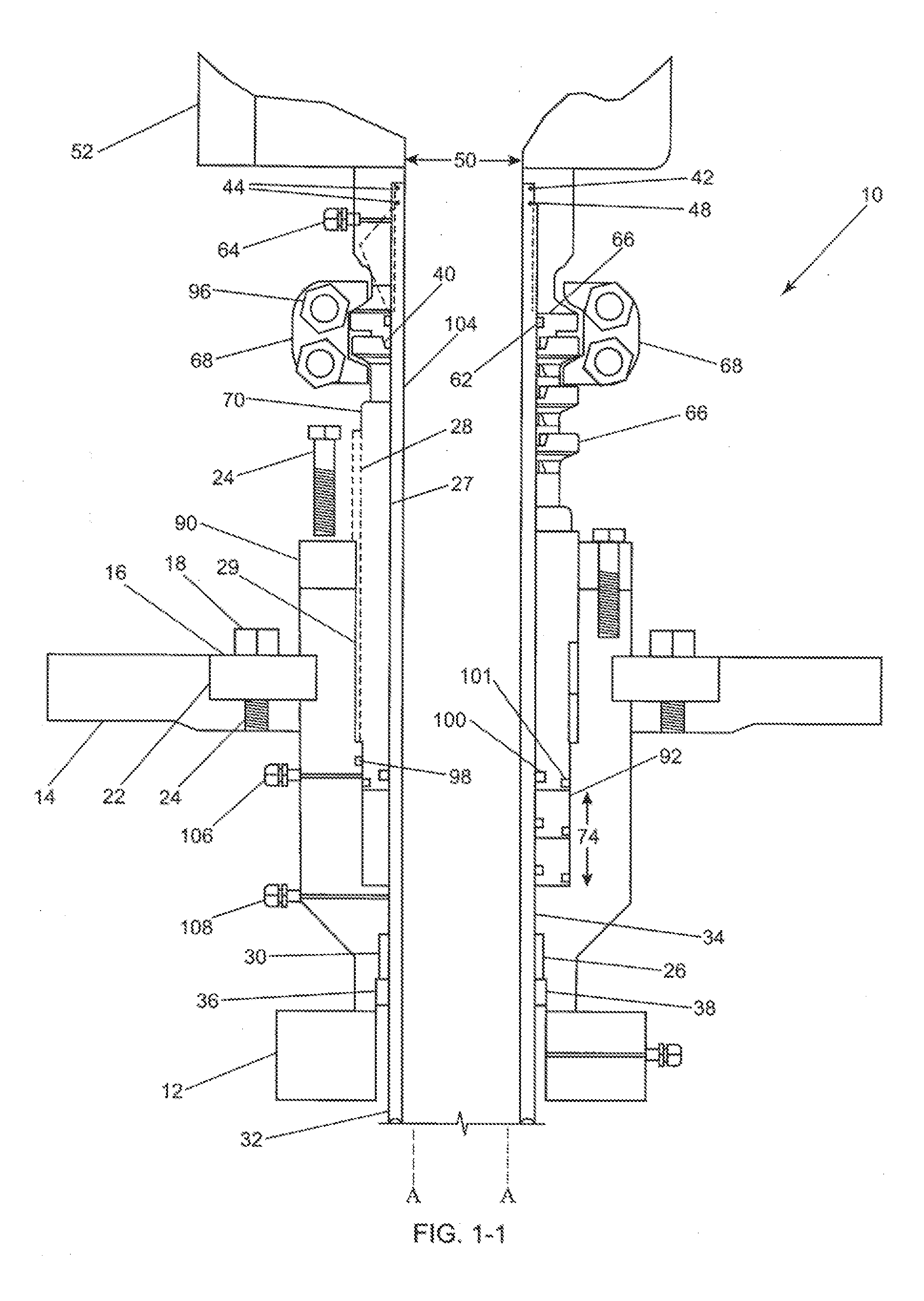
[0025] FIG. 1-1 shows the top half of a cross-sectional exploded view of the preferred unibody master housing assembly with variable adjuster locking sleeve adapter assembly viewed in various positions of vertical installation positions.
[0026] FIG. 1-1 also shows the variable high pressure transition tube in an exploded view inserted into the pressure transition control valve. It features the external test ports for testing pressure transition tube seals and locking mechanism metal seal, shank plate and locking ring installed in the master housing, backup variable adjuster locking sleeve adapter retainer ring, with internal and external tube seals with upper and lower test ports to test seal integrity of unibody master housing and pressure transition tube.
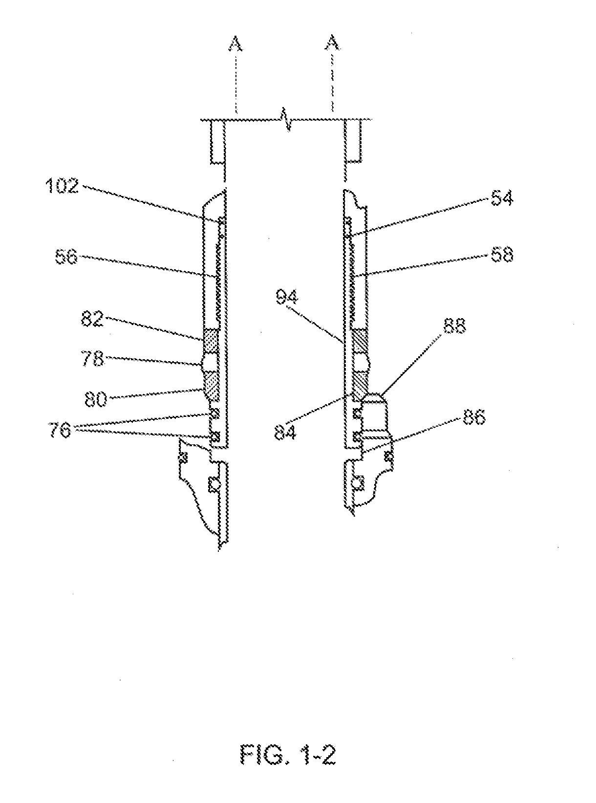
[0027] FIG. 1-2 is the bottom half of the cross-sectional exploded view of the preferred high pressure variable tube assembly with the hollow bullet nose seal assembly installed in the variable tube and inserted into the wellhead casing secondary seal. FIG. 1-2 illustrates the metal energizer compression ring seated to the top of the secondary seal bit guide, the elastomer compression seal protruding or pushing outwards as force is applied to compress against the bore wall of the wellhead and two different forms of seals working simultaneously.
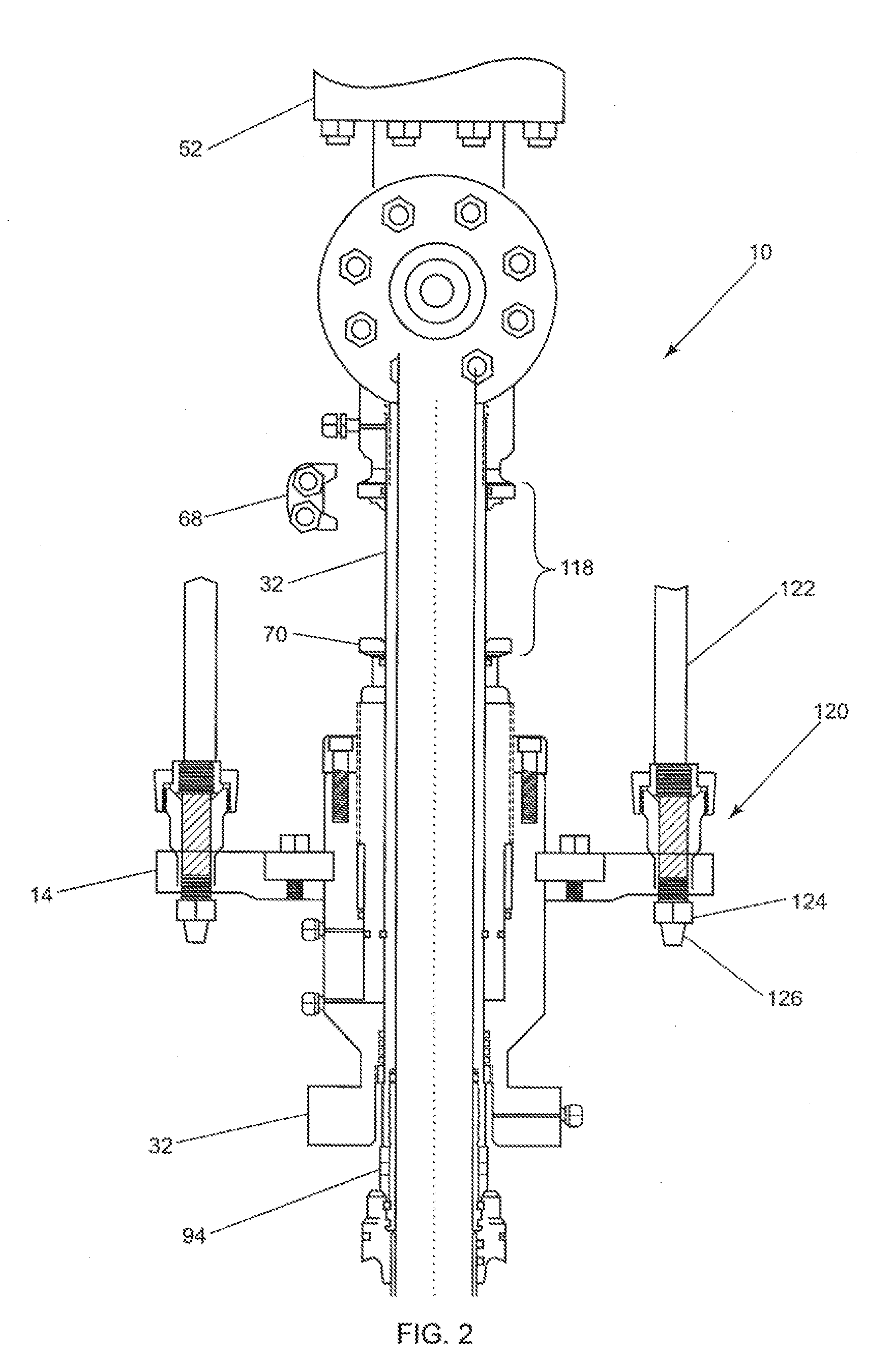
[0028] FIG. 2 is a cross-sectional view of the variable adjuster locking assembly and unibody master housing assembly with variable adjuster locking sleeve assembly disengaged as shown in FIGS. 1-1 and 1-2. It also illustrates the variable high pressure transition extracting out and away from the disengaged variable adjuster locking sleeve and traveling up in a vertical path away from the unibody master housing and traveling through the variable adjuster locking sleeve adapter and seals. FIG. 2 also illustrates how the secondary locking ring works independent of the primary locking assembly.
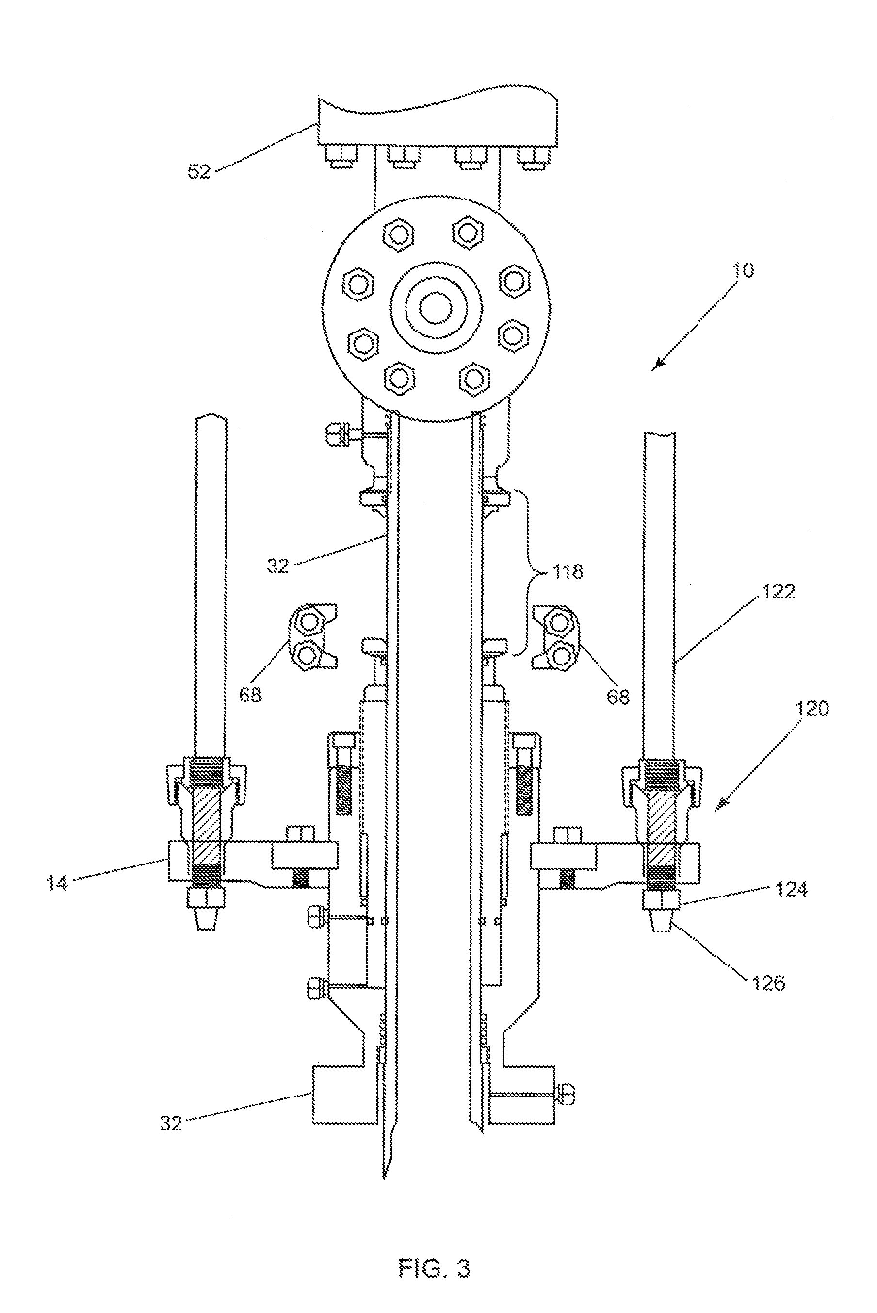
[0029] FIG. 3 is a front view of unibody master housing assembly cross section with high-pressure variable transition tube and quick connect shank rod connection assembly mounted to the shank rod plate with shank rod inserted and securely locked into position with a safety back up lock nut installed.
[0030] FIG. 4 is an alternate flanged frack valve adapter embodiment to the unibody pressure transition control valve adapter and locking clamp mechanism used in the high pressure transition tube well control equipment protector.
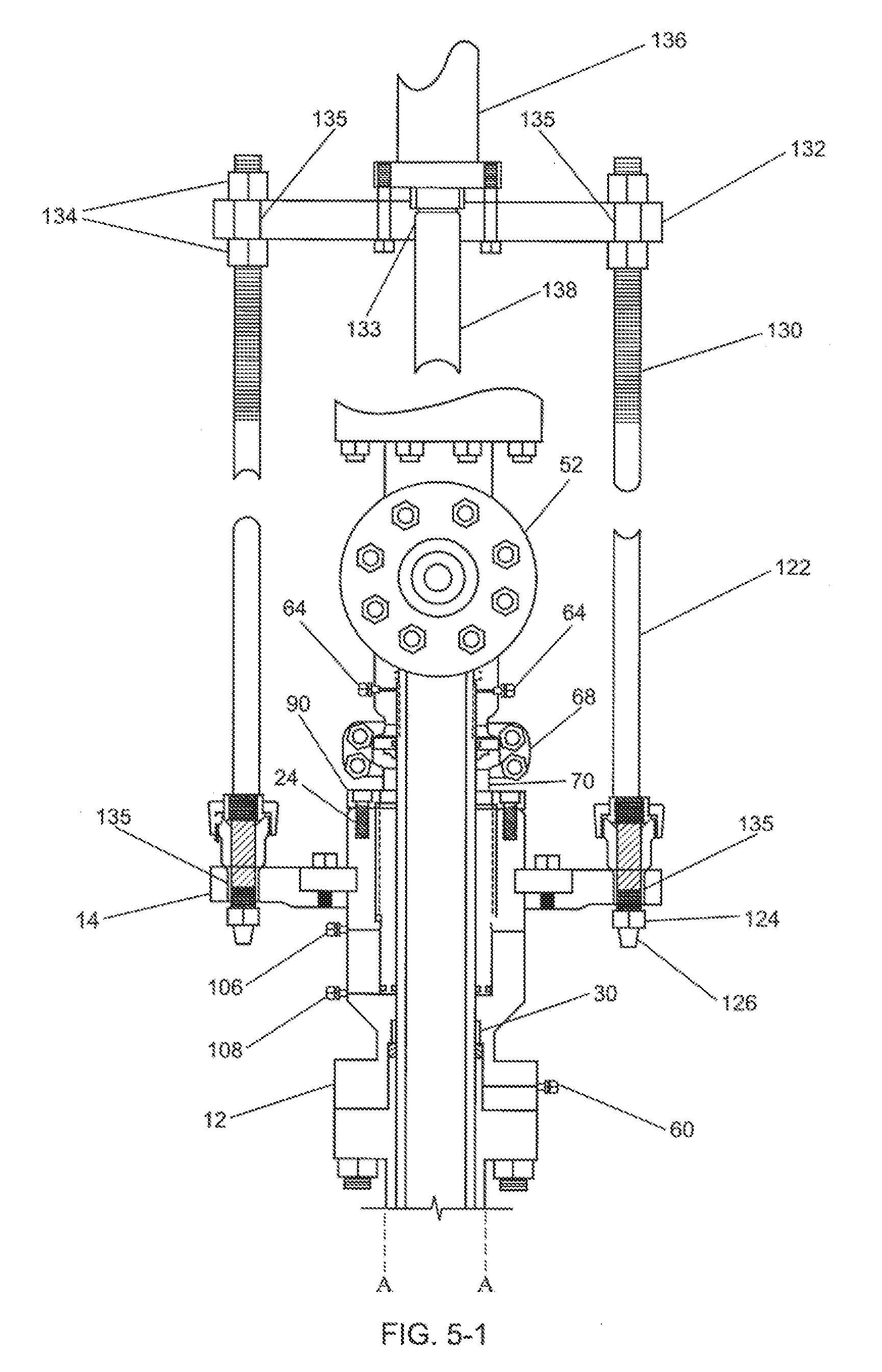
[0031] FIG. 5-1 is a front view of the variable high pressure transition tool assembly mounted on well control equipment with the upper and lower shank rod plate assemblies and ram assembly mounted to the shank rod plate with variable adjustable shank rods.
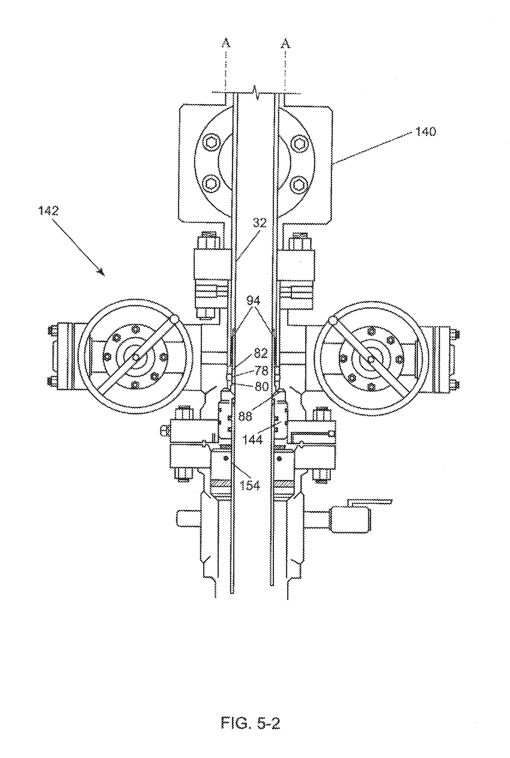
[0032] FIG. 5-2 is a partial cross-sectional view of a variable high pressure transition tube and an embodiment of seal assembly inserted and attached to a variable high pressure transition tube for sealing against an inner wall of well control equipment.
[0033] FIG. 6 is a partial cross-sectional view of an alternate preferred embodiment of an annular sealing body for sealing against the inner wall. It is inserted into a preinstalled casing sealing assembly that is inserted and installed to the casing and mounted and secured in the well control equipment.
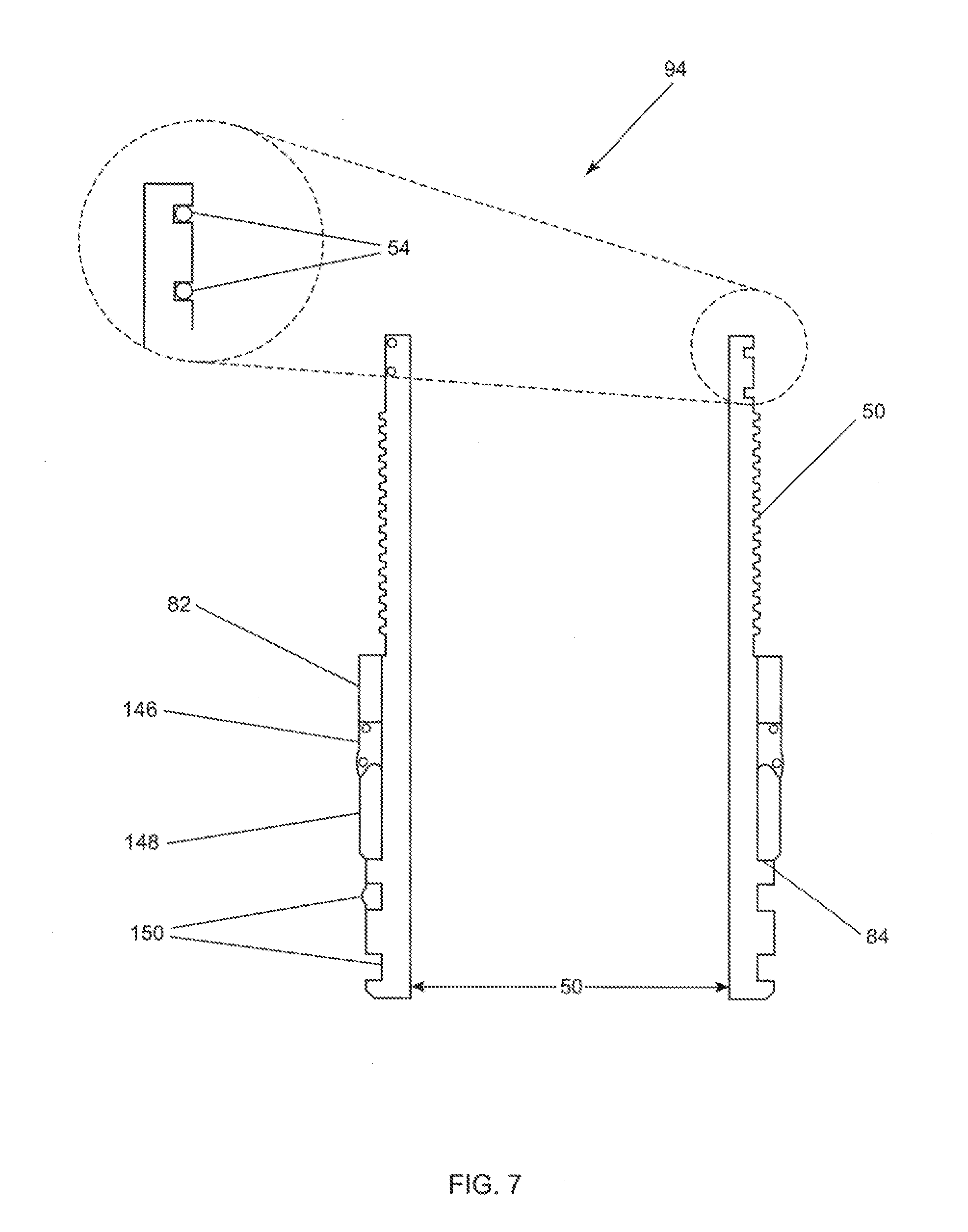
[0034] FIG. 7 is a partial cross-sectional view of an alternate preferred embodiment of an annular sealing body for sealing against the inner wall of the well control equipment with a metal to metal compression ring that seats or butts up to the tool guide of the casing seal. It is then compressed by force, which preloads and energizes the seal or seals against the inner wall of well control equipment to positively provide a seal.
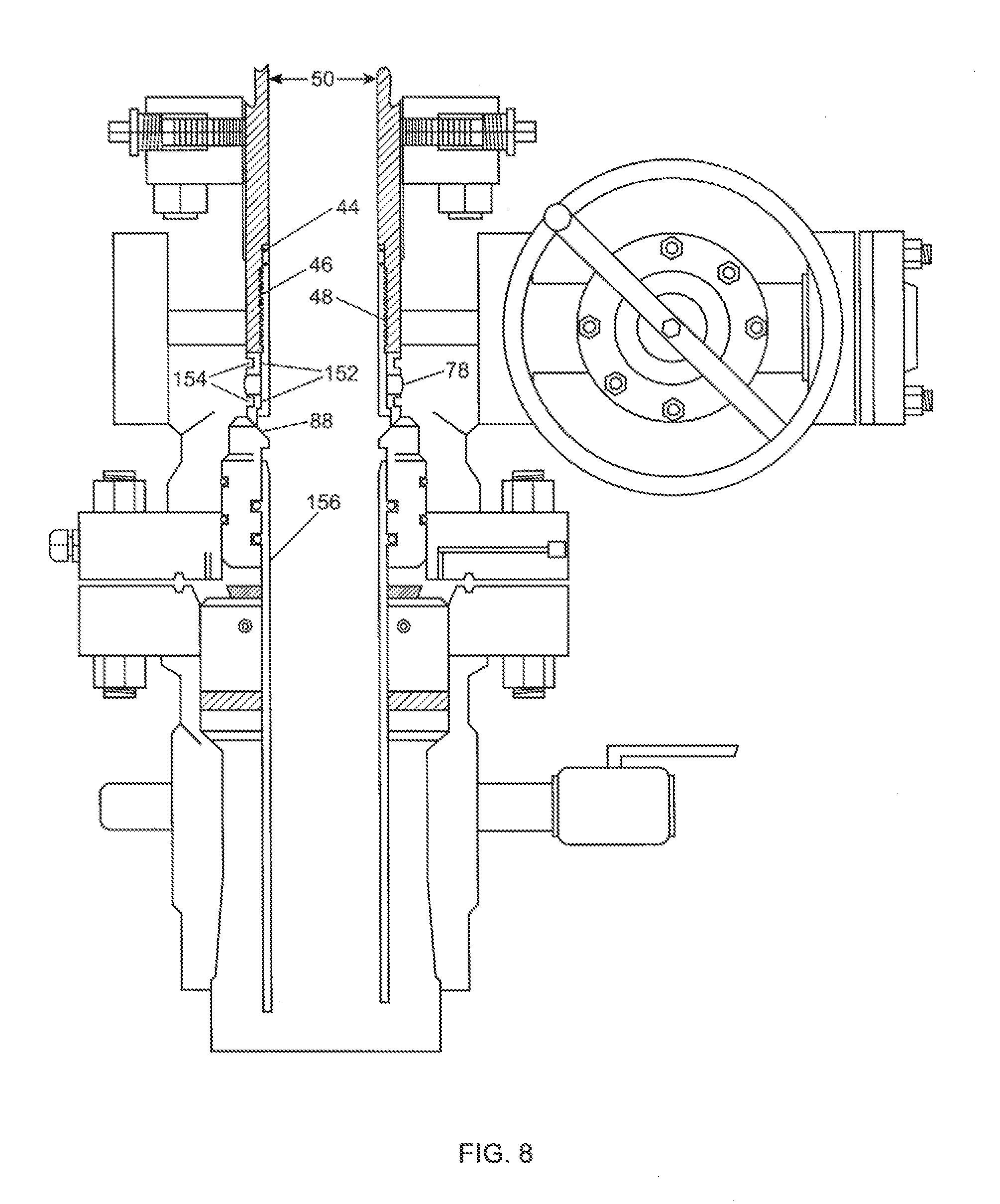
[0035] FIG. 8 is an embodiment of an alternate seal of FIG. 5-2 illustrating a metal ring in contact with a casing secondary seal bit guide used to energize an elastomer or polyurethane seal when pressure is applied and used to compress the seal against the body of the wellhead bore. This force pushes the seal outward against the bore, which does not require controlled tolerances.
DESCRIPTION OF THE PREFERRED EMBODIMENTS BEST MODES FOR CARRYING OUT THE INVENTION
[0036] FIGS. 1-1 and 1-2 show a cross-sectional view of the variable high pressure transition tool for protecting the wellhead control equipment (hereinafter referred to as variable pressure isolation tool) 10. Variable pressure isolation tool 10 includes a unibody master housing 12, a shank rod plate 14 that is drilled, tapped, and prepped with bolt threads uniformly positioned around the radius of shank rod plate 14. Shank rod plate bolts 18 are affixed to shank rod plate 14 and to split locking ring 16 that are then placed into position on unibody master housing 12 by sliding shank rod plate 14 over the top of upper member of unibody master housing 12. Unibody master housing 12 can also include at least two or more split retainer rings 20 that include bolt holes around the radius of split locking ring 16 with vertically aligning holes in shank rod plate 14. Split locking rings 16 are inserted into position in unibody master housing locking ring slot groove 22, shank rod plate 14 is lifted into position, and the hole aligned with split locking ring 12. One or more shank rod plate bolts 18 are inserted into the aligned holes and rotated into retainer ring bolt threads 24 and tightened or torqued into position. Unibody master housing 12 is machined and configured with a tube seal pocket 26, fitted and sized with seal 30 interference against the vertical wall of variable tube seal pocket prep 26 that will accept one or more tube seals 30. Variable high pressure transition tube 32 is inserted into and through vertical bore 34 of unibody master housing 12 and one or more tube seals 30 are inserted and placed into position around variable high pressure transition tube 32. Packing retainer ring 36 is placed around variable high pressure transition tube 32 and slid into position until packing retainer ring 36 makes contact with retainer ring threads 38, and is then rotated into position and locked in place. Variable high pressure transition tube 32 is fitted and prepped with male High Pressure (HP) nose seal prep 42. HP nose seal prep 42 is fitted with at least one or more high pressure tube seals 44 with spiral threads 46 to engage with complementary unibody pressure transition control valve spiral threads 48 and tube bore 50. Tube bore 50 should be large enough to provide full access to the well bore casing as shown in FIG. 2. Spiral threads 56 are used to engage with variable high pressure transition tube complementary spiral threads 58 and at least one tube seal upper 60 and a lower outer variable tube seal 62. Unibody pressure transition control valve 52 has a variable tube test port 64 that enables testing from 10,000 to 15,000 PSI on tube seal upper 44, and lower outer variable tube seals lower 62 for safety and seal integrity. Unibody pressure transition control valve 52 is prepped with integrated locking clamp preparation 66 flanged or winged hub (not shown).
[0037] Variable high pressure transition isolation tool assembly 32 is also adapted with a variable adjuster locking sleeve 70 with spiral variable adjustable threads 28 that are provided externally for adjusting the sleeve up or down 92 into position to mate with the setting position of a unibody pressure transition control valve 52 and variable high pressure transition tube 32. Variable adjuster locking sleeve 70 is fitted with inner tube seal 100 and outer seal 102 to prevent escape or spill of any pressurized liquids that might be present should seal 78 and tube seal 30 be damaged or have hollow nose bullet seal body assemblies 94 that are mated with wellhead seal prep 86 leak. Hollow nose bullet seal body assembly 94 is fitted with external complementary spiral threads 56 and internal complimentary threads 58 that have at least one external elastomer seal 78 and lower energizer ring 80. Lower energizer ring 80 is installed by placing it over and sliding the upper external threads 56 and lowering it to no go stop 84. Elastomer compression seal 78 and upper energizer ring 82 are installed using the same steps.
[0038] Bullet nose hollow seal assembly 94 is installed into variable high pressure transition tube 32 by rotating complementary threads 56 and 58 until hollow nose bullet seal assembly 94 stops rotating and is fully engaged. When bullet nose hollow seal assembly 94 engages and is set inside wellhead seal prep 86 with lower energizer ring 80, it stops on top of wellhead seal bit guide 88. Force is applied by means of weight or hydraulic (not shown) to the top of variable high pressure transition tool 10 which forces upper energizer ring 82 to push against elastomer compression seal 78 and lower energizer ring 80 compressing and preloading the seal against the wellhead vertical wall. Variable adjuster locking sleeve 70 is usually pre-set to the lowest operation position of variable adjustment 74 by rotating clockwise or counter clockwise on threads 28 of the variable adjuster tube sleeve and master housing thread 29 to match the final optimum setting position of hollow nose seal assembly 94 and unibody pressure transition valve 52. Locking clamp 68 flange or winged connection (not shown) is installed and locked in the optimum position and clamp bolts 96 are installed and secured into position.
[0039] Variable adjuster locking sleeve 70 is fitted with well-known types or methods for locking clamping or bolting hub prep 68 and fitted with steel seal ring prep 40 as a backup pressure containment barrier if lower tube seal 102, 78 fails. Variable adjuster locking sleeve 70 is fitted with an inner seal 100 and outer seal 102 master housing seal 98 to prevent exposure and spills should tube seal 102, hollow bullet nose seals 76, or compression seal 78, and master housing seal 30 fail. Variable adjuster locking sleeve 70 also provides a passage bore for variable high pressure transition tube 32 to pass through and travel up and down or in and out of locking sleeve barrier bore 104. Variable adjuster locking sleeve 70 is fitted with an upper test port 106 to test master housing outer locking sleeve seal 98, 102 for seal integrity. Lower test port 108 provides for testing locking sleeve inner seal 100 and tube seal 30 for seal integrity.
[0040] FIGS. 2 and 3 illustrate the variable high pressure transition tool of FIGS. 1-1 and 1-2, prior to being mounted above well control equipment for a well stimulation treatment. Locking clamp 68 is removed from variable adjuster locking sleeve 70 and the lockdown mechanism is disengaged from unibody high pressure control valve 52 and away from unibody master housing 118. Rod shank plate 14 and unibody high pressure control valve 52 are connected to the top end of variable high pressure transition tube 32, which includes any required proper variable high pressure transition tube length section(s) and hollow nose bullet seal packoff assembly 76 to provide a total length required for a particular well control equipment or wellhead. Unibody master housing 118 is mounted on the top end of the well control equipment or BOP and the combination of unibody high pressure control valve 52 with lockdown clamp 68 and variable high pressure transition tube 32, are inserted from the top into the well control equipment or BOP using any one of several insertion tools known in the industry. Rod shank plate 14 is fitted with at least two or more rod quick connect assemblies 120 for attaching upper rod shank plate (not shown) and lower rod shank plate 14, at least two or more variable rod shanks 122, and at least two or more rod safety nuts 124 for backup security while inserting or pulling under pressure.
[0041] FIG. 4 illustrates a flanged end valve adapter 128 fitted and prepped with a female HP nose seal prep 42. Flanged end valve adapter 128 has spiral threads 46 to engage with variable high pressure transition tube complementary spiral threads 48 that have at least one tube seal upper 44 and lower outer variable tube 32. Flanged end valve adapter 128 has a variable tube test port 64 that enables testing of 10,000 to 15,000 PSI on tube seal upper 44 and outer variable tube seals lower 62 for safety and seal integrity. Flanged end valve adapter 128 is prepped with integrated locking clamp 66 flanged or winged hub (not shown).
[0042] The variable high pressure transition tool in FIGS. 5-1 and 5-2 illustrates an example of the use of well control equipment and wellhead protector 10, shown in FIGS. 1-1 and 1-2, using a hydraulic setting tool as described in U.S. Pat. No. 4,867,243, which is incorporated herein by reference. The tool is connected to casing well bore by various casing methods that are well known in the industry using equipment such as a tubing head and tubing spool. Well control equipment are parts and devices known in the oil and gas industry as wellhead equipment, wellhead components and parts, blow out preventers that are also well known in the oil and gas industry and not described in this disclosure. Mounted above the wellhead assembly is the well control equipment that is used for pressure and fluid flow control during the fracking procedure and well treatment. The equipment is also used to secure and prevent well fluids from escaping into the atmosphere.
[0043] FIG. 5-1 shows variable high pressure transition tool assembly 10 mounted to well control equipment 140, unibody high pressure frack valve 52 mounted to the top of variable high pressure transition tube 32 to control well pressure and or fluid during the insertion and removal of variable high pressure transition tube 32 to prevent well fluids from escaping to atmosphere. FIG. 5-1 shows the system before variable high pressure transition tool 10 is installed or removed. High pressure valve 52 is hydraulically or manually operated or controlled. Hydraulic setting tool 136 includes a hydraulic cylinder, which is mounted to upper rod shank plate 132. Upper shank rod plate 132 includes passage 133 to permit a piston rod for hydraulic cylinder 138 to pass through upper shank rod plate 14. Upper shank rod plate 132 also includes at least two attachment points 135 for attachment of variable rod shank 122 to shank rod plate 14. Variable rod shank attachment points 135 are preferably equally spaced from central bore 133 to ensure that the hydraulic cylinder and the piston rod align with unibody pressure transition control valve 52 to which the hydraulic cylinder attachment (not shown) is mounted. The hydraulic cylinder and variable rod shank 122 are respectively attached on their lower shank rod plate 14 ends at corresponding attachment points on the plate, which is mounted to the top of well control equipment 140. Lower shank rod plate 14 is supported by two or more variable rod shanks 122 that are identical in length and are manufactured with course threads described as variable rod shank adjustment threads 130. This permits the upward or downward adjustment of upper shank rod plate 132 by rotating adjustment nuts 130 to accommodate variations in lengths or size of equipment. Shank rods 122 are attached to the respective attachment points 135 and 120 on upper shank rod plate 132 and lower shank rod plate 14 by means of rod quick connect assembly 120 comprising of threads or pins and nuts (not shown).
[0044] Piston polish rod 133 is attached to the top of the high pressure valve 52 by a connector so that mechanical force can be applied by pushing and applying force to top of unibody wireline valve adapter of well control to well control equipment 140 protector and the attached high pressure valve to stroke them in and out of the wellhead. When variable high pressure transition tube 32 is in the operative position shown in FIG. 5-2, the bottom end of metal energizer ring assembly 80 is in contact with a bit guide 88 attached to a top of casing wellhead seal 144. Bit guide 88 covers casing 145 to protect the top end of casing 145 and provides a seal between casing 145 and wellhead assembly 142 in a manner well known in the industry as a secondary seal or wellhead seal 144.
[0045] As noted above, variable high pressure transition tube 32 has a variable length adjustment 74 as illustrated FIG. 1-1, so that hollow nose seal assembly 94, including upper compression seal ring 82, compression packoff 78, and lower compression ring 80, have adequate length to ensure that the top end of variable adjuster locking sleeve 70 extends above the top of unibody master housing 22 with just enough up and down adjustment 74 to rotate and contact with unibody pressure transition valve 52. Hollow nose seal assembly 94 is secured by lockdown assembly clamp 68 described above when packoff assembly 62 is seated against bit guide 94. However, the distance from the top of bit guide 94 and the top of well control equipment 74 may vary to some extent in different wellheads. This variation cannot be accommodated by a conventional lockdown mechanism such as taught in Applicant's U.S. Pat. No. 4,867,243. The presently claimed invention overcomes this shortcoming.
[0046] FIG. 6 shows hollow bullet nose seal assembly 94, which comprises four parts with a unique design that eliminates the need for a retainer ring or no go. The assembly has a lower ring 80, known as the lower energizer ring, which seats or contacts the top of wellhead secondary seal 88, known as the wellhead bit guide. Lower energizer ring 80 is installed over bullet nose 94 and thread 58 and slid down to no go stop 84. Compression seal 78 is installed by placing it over the top of the bullet nose seal and then slipped over threads 58 to lower energizer ring 80. Upper energizer seal ring is also slipped over the top of bullet nose 94 and threads 58 until it contacts compression seal 78. Hollow bullet nose seal assembly 94 is now installed to the bottom of high pressure variable transition tube 32, as shown in FIG. 1-2
[0047] As shown in FIG. 7, hollow bullet nose seal assembly 94 is comprised of four parts with a unique design that eliminates the need for a retainer ring or no go. The assembly has a lower ring 148, known as the lower energizer ring that seats or contacts the top of wellhead secondary seal 88 (not shown), known as the wellhead bit guide. Lower energizer ring 148 is designed with a radius taper positioned to force elastomer seal 148 outward to force compression against the outer wall of the wellhead through bore as illustrated in FIG. 5-2. The more force that is applied, the tighter the seal is applied to the bore wall ensuring a compression seal. Compression seal 146 is installed over the nose and thread 58 and slid down to no go stop 84. Compression seal 146 is installed by placing it over the top of the bullet nose seal and slipped over threads 58 to lower energizer ring 148. The radius taper design of compression seal 148 matches the radius taper of bottom seal energizer ring 148. Upper energizer seal ring 82 is also slipped over the top of bullet nose 94 and threads 58 until it contacts compression seal 146. Hollow bullet nose seal assembly 94 is now installed to the bottom of high pressure variable transition tube 32 as shown in FIG. 1-2.
[0048] FIG. 8 is an embodiment of an alternate seal as shown FIG. 5-2. FIG. 8 illustrates a metal energizer ring in contact with a casing secondary seal bit guide 88 used to energize an elastomer or polyurethane seal 78 when force is applied and used to compress the seal against the body of the wellhead bore known in the industry as a through bore. This force pushes the seal outward against the bore, which does not require a controlled tolerance or measurement, as in prior art energizer rings. Polyurethane seal 78 is equipped with an outer seal prep 154 and an inner seal prep 152 (not shown), these seals serve to pressure energize the compression seal 78 without the need for compression. Compression is achieved by inner bore pressure, which forces the compression of seal 78. The more pressure, the more compression, and the tighter the seal. Bullet nose seal 94 is inserted and rotated into position by spiral threads 46 and complimentary threads 48 into high pressure tube where seals 44 contact high pressure inner wall seal prep. Bore of tube 50 is equal to casing wall 156 which gives the user full access to the well bore allowing tools to be inserted in and out of the well
[0049] Although the claimed invention has been described in detail with particular reference to these preferred embodiments, other embodiments can achieve the same results. Variations and modifications of the presently claimed invention will be obvious to those skilled in the art and it is intended to cover in all such modifications and equivalents. The entire disclosures of all references, applications, patents, and publications cited above, are hereby incorporated by reference.
* * * * *
D00000
D00001
D00002
D00003
D00004
D00005
D00006
D00007
D00008
D00009
D00010
XML
uspto.report is an independent third-party trademark research tool that is not affiliated, endorsed, or sponsored by the United States Patent and Trademark Office (USPTO) or any other governmental organization. The information provided by uspto.report is based on publicly available data at the time of writing and is intended for informational purposes only.
While we strive to provide accurate and up-to-date information, we do not guarantee the accuracy, completeness, reliability, or suitability of the information displayed on this site. The use of this site is at your own risk. Any reliance you place on such information is therefore strictly at your own risk.
All official trademark data, including owner information, should be verified by visiting the official USPTO website at www.uspto.gov. This site is not intended to replace professional legal advice and should not be used as a substitute for consulting with a legal professional who is knowledgeable about trademark law.