Modular Coiled Tubing Bottom Hole Assembly
Wisinger JR.; John Leslie ; et al.
U.S. patent application number 16/311659 was filed with the patent office on 2019-07-04 for modular coiled tubing bottom hole assembly. The applicant listed for this patent is Halliburton Energy Services, Inc.. Invention is credited to John Leslie Wisinger JR., Jonathan Peter Zacharko.
| Application Number | 20190203538 16/311659 |
| Document ID | / |
| Family ID | 60953324 |
| Filed Date | 2019-07-04 |


| United States Patent Application | 20190203538 |
| Kind Code | A1 |
| Wisinger JR.; John Leslie ; et al. | July 4, 2019 |
MODULAR COILED TUBING BOTTOM HOLE ASSEMBLY
Abstract
A system and method to minimize trips in a wellbore during coiled tubing operations by simultaneously deploying on coiled tubing as part of the bottom hole assembly a wireline tool and an intervention tool. The wireline tool includes a flow through passage to permit a working fluid to flow through the wireline tool to the intervention tool during operations. The intervention tool may be adjusted in real time based on the measurements from the wireline tool.
| Inventors: | Wisinger JR.; John Leslie; (Spring, TX) ; Zacharko; Jonathan Peter; (Spring, TX) | ||||||||||
| Applicant: |
|
||||||||||
|---|---|---|---|---|---|---|---|---|---|---|---|
| Family ID: | 60953324 | ||||||||||
| Appl. No.: | 16/311659 | ||||||||||
| Filed: | July 14, 2016 | ||||||||||
| PCT Filed: | July 14, 2016 | ||||||||||
| PCT NO: | PCT/US2016/042344 | ||||||||||
| 371 Date: | December 19, 2018 |
| Current U.S. Class: | 1/1 |
| Current CPC Class: | E21B 19/16 20130101; E21B 47/135 20200501; E21B 44/00 20130101; E21B 21/103 20130101; E21B 10/08 20130101; E21B 17/206 20130101; E21B 17/02 20130101; E21B 23/06 20130101; E21B 47/01 20130101 |
| International Class: | E21B 10/08 20060101 E21B010/08; E21B 17/02 20060101 E21B017/02; E21B 19/16 20060101 E21B019/16; E21B 23/06 20060101 E21B023/06; E21B 47/01 20060101 E21B047/01 |
Claims
1. A bottom hole assembly for coiled tubing operations, the bottom hole assembly comprising: a coiled tubing connector head having a tubular body with a through bore and at least one cable connector; an analytic tool secured to the connector head, the analytic tool having a through bore and an analytic tool cable connector mated with the cable connector of the connector head; and an intervention tool secured to the analytic tool.
2. The bottom hole assembly of claim 1, wherein the analytic tool is selected from the group consisting of setting tools, gamma perforating tools, casing collar locators, cement bond tools, cement bond tools, sonic and ultrasonic tools, resistivity tools, nuclear tools, natural gamma ray tools, flow meters.
3. The bottom hole assembly of claim 1, wherein the intervention tool is selected from the group consisting of a drill bit, a milling bit, a cleaning tool, a stimulation tool, a fishing tool, a recovery tool, perforating tool, jetting tool, pipe cutters, settable plugs and packers, or downhole valves.
4. The bottom hole assembly of claim 1, wherein said analytic tool comprises an upper engagement mechanism at a first end of the analytic tool and a lower engagement mechanism at a second end of the analytic tool, wherein the upper engagement mechanism attaches to the engagement mechanism of the coiled tubing connector head and the lower engagement mechanism attaches to an engagement mechanism of the intervention tool.
5. The bottom hole assembly of claim 1, further comprising a circulating sub secured between the connector head and the analytic tool, the circulating sub comprising an elongated tubular having a first end and a second end with a through bore extending between the two ends, ports formed in the tubular and a valve mechanism to selectively alter fluid flow through the bore from the first end of the tubular to either the second end of the tubular or the ports, the circulating sub further having an upper circulating sub connector engaged with the cable connector and a lower circulating sub connector engaged with the analytic tool cable connector.
6. The bottom hole assembly of claim 1, wherein the analytic tool has a first end and a second end and comprises a pass through bore extending along an axis between the two ends with a centralizer supporting a sensor mechanism along the analytic tool bore axis.
7. The bottom hole assembly of claim 6, further comprising a first circulating sub secured between the coiled tubing connector head and the analytic tool and a second circulating sub secured between the analytic tool and the intervention tool, the circulating subs in a first configuration permitting flow through the first circulating sub from the connector head, past the pass through bore in which the sensor mechanism is supported and to the intervention tool and a second configuration in which a first flow path from the first circulating sub bypasses the sensor mechanism and a second flow path from the second circulating sub passes through the bore in which the sensor mechanism is supported.
8. A coil tubing system for performing operations in a wellbore, the coiled tubing system comprising: coiled tubing forming an inner flow bore and having a distal end; a hybrid cable deployed in the inner flow bore of the coiled tubing, the cable including at least one fiber optic and one electric conductor; a connector head attached to the distal end of the coiled tubing, the connector head having at least one cable connector optically coupled to the fiber optic cable; an analytic tool secured to the connector head, the analytic tool having an first analytic tool cable connector mated with the cable connector of the connector head; and a first intervention tool secured to the analytic tool.
9. The coil tubing system of claim 10, wherein the hybrid cable further comprises at least one electric cable and the connector head comprises an electric cable connector electrically coupled to the electric cable.
10. The coil tubing system of claim 11, further comprising a first circulating sub secured between the connector head and the analytic tool, the circulating sub having an elongated tubular with a first end and a second end and a through bore extending between the two ends, ports formed in the tubular and an electric valve mechanism to selectively alter fluid flow through the bore from the first end of the tubular to either the second end of the tubular or the ports, the circulating sub further having an first circulating sub connector electrically connected to the electric valve mechanism, the first circulating sub connector mated with the cable connector of the connector head, and a second circulating sub connector electrically connected to the first circulating sub connector, the second circulating sub connector mated to the first analytic tool connector; and a treatment tool secured between the analytic tool and the first intervention tool, the treatment tool having an elongated tubular with a first end and a second end and a through bore extending between the two ends, ports formed in the tubular and an electric valve mechanism to selectively direct fluid flow from the through bore of the treatment tool to the ports of the treatment tool, the treatment tool further having a first treatment tool connector mated with the second analytic tool connector, the first treatment tool connector electrically connected to the electric valve mechanism of the treatment tool, wherein the through bores of the connector head, the circulating sub, the analytic tool, the treatment tool and the first intervention tool are in fluid communication with one another.
11. A method of conducting stimulation of a wellbore, the method comprising deploying on coiled tubing into a wellbore a wireline tool and a intervention tool; setting a packer at a first location in the wellbore; pumping a working fluid down the coiled tubing, through the wireline tool to a first treatment zone; introducing the working fluid into the first treatment zone utilizing a jetting tool; releasing the packer at the first location in the wellbore; utilizing the coiled tubing to move the jetting tool to a second treatment zone; setting the packer at a second location in the wellbore; pumping a working fluid down the coiled tubing, through the wireline tool to the second treatment zone; introducing the working fluid into the second treatment zone utilizing the jetting tool.
12. The method of claim 13, further comprising perforating the wellbore casing while the jetting tool is deployed, and thereafter, continuing with the step of setting the packer at a first location.
13. The method of claim 13, further comprising utilizing a wireline tool to make a measurement in the wellbore after the chemical introduction, but before release of the packer, wherein the wireline tool is selected from the group consisting of gamma perforating tools, casing collar locators, cement bond tools, cement bond tools, sonic and ultrasonic tools, resistivity tools, nuclear tools, natural gamma ray tools, flow meters.
14. The method of claim 13, further comprising utilizing a wireline tool to make a measurement in the wellbore during chemical introduction.
15. The method of claim 13, further utilizing the wireline tool to monitor in real time the effects of the chemical treatment on a parameter of the wellbore.
16. The method of claim 13, further comprising adjusting the chemical treatment in real time based on the real time monitoring of the wellbore.
17. The method of claim 13, further comprising adjusting a stimulation treatment in real time based on feedback from sensors supported on the coiled tubing adjacent a stimulation zone.
18. A method of conducting coiled tubing operations in a wellbore, the method comprising: deploying on coiled tubing into a wellbore a wireline tool and an intervention tool suspended below the wireline tool; pumping a first fluid along a first flow path through the wireline tool to the intervention tool; actuating a circulating valve to direct a second fluid along a second flow path around the wireline tool; and pumping a second fluid along the second flow path.
19. The method of claim 18, further comprising utilizing the wireline tool to make measurements while the first fluid is pumped along the first flow path; and suspending the measurements while the second fluid is pumped along the second flow path.
20. The method of claim 19, further comprising utilizing the intervention tool to perform a task selected from the group consisting of perforating wellbore casing, milling wellbore casing, drilling a wellbore and drilling a plug.
21. The method of claim 20, further comprising utilizing the wireline tool and the intervention tool simultaneously.
22. The method of claim 21, further comprising adjusting the mechanical intervention task in real time based upon monitoring by the wireline tool.
Description
TECHNICAL FIELD
[0001] The present disclosure generally relates to oilfield equipment and, in particular, to downhole tools, drilling and related systems and techniques for coiled tubing operations in a wellbore. More particularly still, the present disclosure relates to systems and methods for conducting stimulation and diagnostic monitoring in coiled tubing operations in a single run.
BACKGROUND
[0002] Coiled tubing may be used in a variety of wellbore servicing operations including drilling operations, completion operations, stimulation operations, workover and other operations. Coiled tubing generally refers to relatively flexible, continuous small diameter cylindrical tubing having a thin wall made of metal or composite material that can be run into the wellbore from a large spool which may be mounted on a truck or other support structure. Coiled tubing may be used, for example, to inject gas or other fluids into the wellbore or pipeline, to inflate or activate bridges and packers, to transport tools downhole (such as logging tools), to perform remedial cementing and clean-out operations in the bore, to deliver drilling tools downhole, for electric wireline logging and perforating, drilling, wellbore cleanout, fishing, setting and retrieving tools, for displacing fluids, and for transmitting hydraulic power into the wellbore. The flexible, lightweight nature of coiled tubing makes it particularly useful in deviated wellbores.
[0003] While a rig must stop periodically to make up or break down connections when running drilling pipe or other jointed tubular strings into or out of a wellbore, coiled tubing can be run in for substantial lengths before stopping to join in another strand of coiled tubing, thereby saving considerable time in comparison to operations utilizing jointed pipe. Moreover, coiled tubing is typically much more flexible and lighter weight than conventional drill pipe, and thus requires fewer resources and much less handling equipment on site.
[0004] Conventional handling systems for coiled tubing can include a spool assembly, a gooseneck, and a tubing injector head. Spool assemblies may include a rotating spool for storing coiled tubing, a cradle for supporting the spool, a drive motor, and a rotary coupling. When the coiled tubing is introduced into a wellbore, the tubing injector head draws the coiled tubing stored on the spool and injects the coiled tubing into a wellhead. As the injector feeds coiled tubing into the wellbore, coiled tubing is unrolled or "paid out" from the coiled tubing spool. As the injector withdraws coiled tubing out of the wellbore, coiled tubing is rolled onto or taken up by the coiled tubing spool. The drive motor rotates the spool to pay out the coiled tubing and the gooseneck directs the coil tubing into the injector head. Often, fluids are pumped through the coiled tubing during operations. The rotary coupling is in fluid communication with the coiled tubing and also with a stationary piping manifold and fluid source, such as an acid pumping truck, in order to provide an interface between the spool assembly and the fluid source.
[0005] Attached to the downhole or free end of the coiled tubing is a CT connecter head from which various equipment may be suspended, such as a bottom hole assembly (BHA) or a wireline tool. When used with a BHA, the connector head may be used to deliver fluid flow and transfer tension, compression and torsional loads between the coiled tube and the downhole equipment for various CT operations, such as drilling, perforating, clean-out, stimulation, mill out and the like. In this regard, the BHA may include various through-tubing, intervention equipment used for the CT operations, such as connectors, mills, bits, motors, agitators, jars, fishing tools, toe prep and tubing conveyed perforating tools such as jetting tools. Fluid flow down the coiled tubing can be utilized to actuate or otherwise control the downhole equipment.
[0006] As an alternative to the BHA, wireline equipment may be suspended by the connector head with a wireline extending through the interior of the coiled tubing and connector head to the wireline equipment. In this regard, typically, the wireline, which may include electrical, optical and/or optoelectric cable are spliced to the wireline equipment prior to deployment downhole. The wireline equipment may be utilized to conduct pre- and post-operation analysis of the CT operations. For example, wireline equipment may be deployed to determine the effectiveness of a stimulation operation such as acidizing. Because the wireline tool is supported by the wireline as opposed to the coiled tubing, during wireline operations, pumping of a working fluid is suspended. Notably, the CT connector head used with a BHA is different from the connector head used with wireline tools because it must allow fluid to flow through the BHA as well as making an electrical and optical connection. Thus, when switching between wireline equipment and BHA equipment, the CT connector heads must also be changed to accommodate the particular type of equipment to be deployed.
[0007] Conventionally, it takes several trips into and out of the well to complete a particular CT operation because of the need to change out equipment at the end of the coiled tubing between steps of an operation. For example, a stimulation operation may require a first trip in with a cleanout tool, followed by a trip in with a wireline tool for measurements, followed by stimulation tool to inject chemicals for a particular treatment, followed by a wireline tool for additional post-treatment measurements. For each trip, the coiled tubing must be drawn out of the wellbore by the injector head and re-wound on the reel, after which the equipment for the next particular step, whether wireline or intervention equipment, is secured to the end of the coiled tubing and run-in the wellbore as the CT operation continues. Moreover, in instances where the wireline equipment utilizes fiber optics for communications or measurements, a fiber optic cable must be spliced to the wireline equipment before the wireline equipment is run-in. Where an intervention tool is subsequently required for the next trip of the CT operation, the fiber optic is cut or terminated in order to install the mechanical intervention equipment.
BRIEF DESCRIPTION OF THE DRAWINGS
[0008] Various embodiments of the present disclosure will be understood more fully from the detailed description given below and from the accompanying drawings of various embodiments of the disclosure. In the drawings, like reference numbers may indicate identical or functionally similar elements. Embodiments are described in detail hereinafter with reference to the accompanying figures, in which:
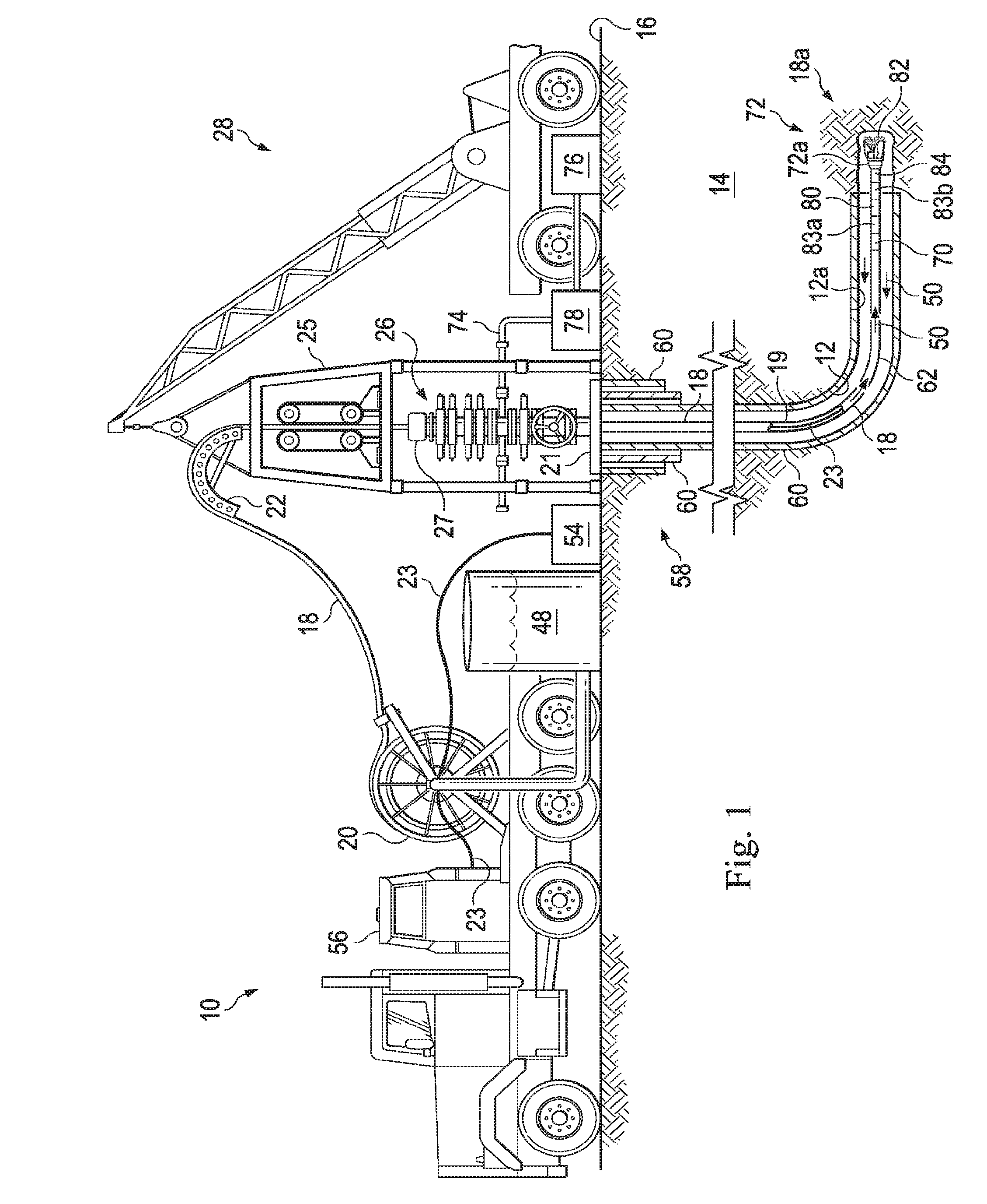
[0009] FIG. 1 is an elevation view in partial cross section of a land-based coiled tubing well system with a flow-through, coiled tubing connector head and a bottom hole assembly with a flow-through wireline tool and an intervention tool according to an embodiment;
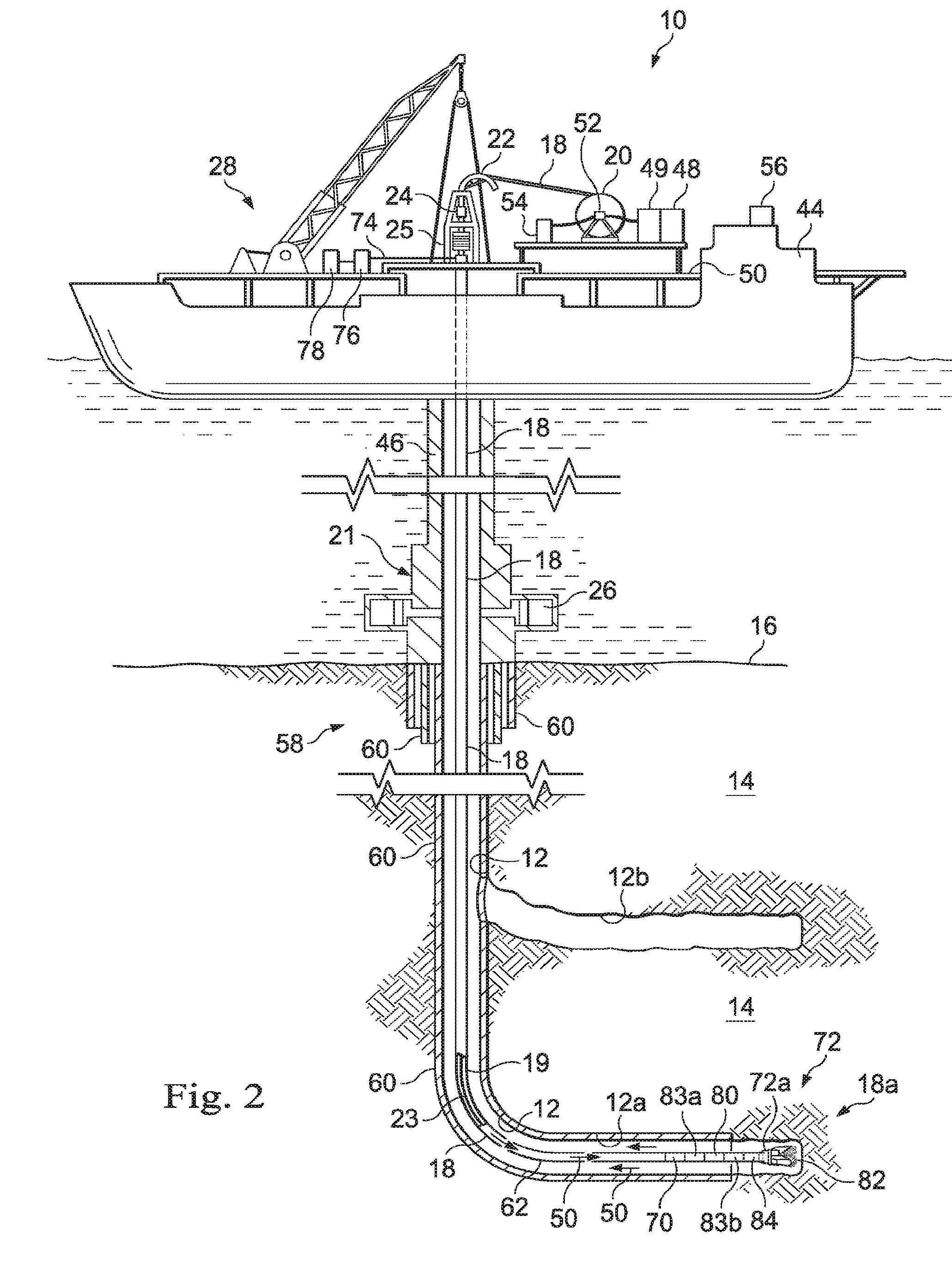
[0010] FIG. 2 is an elevation view in partial cross section of a marine-based coiled tubing well system as shown in FIG. 1;
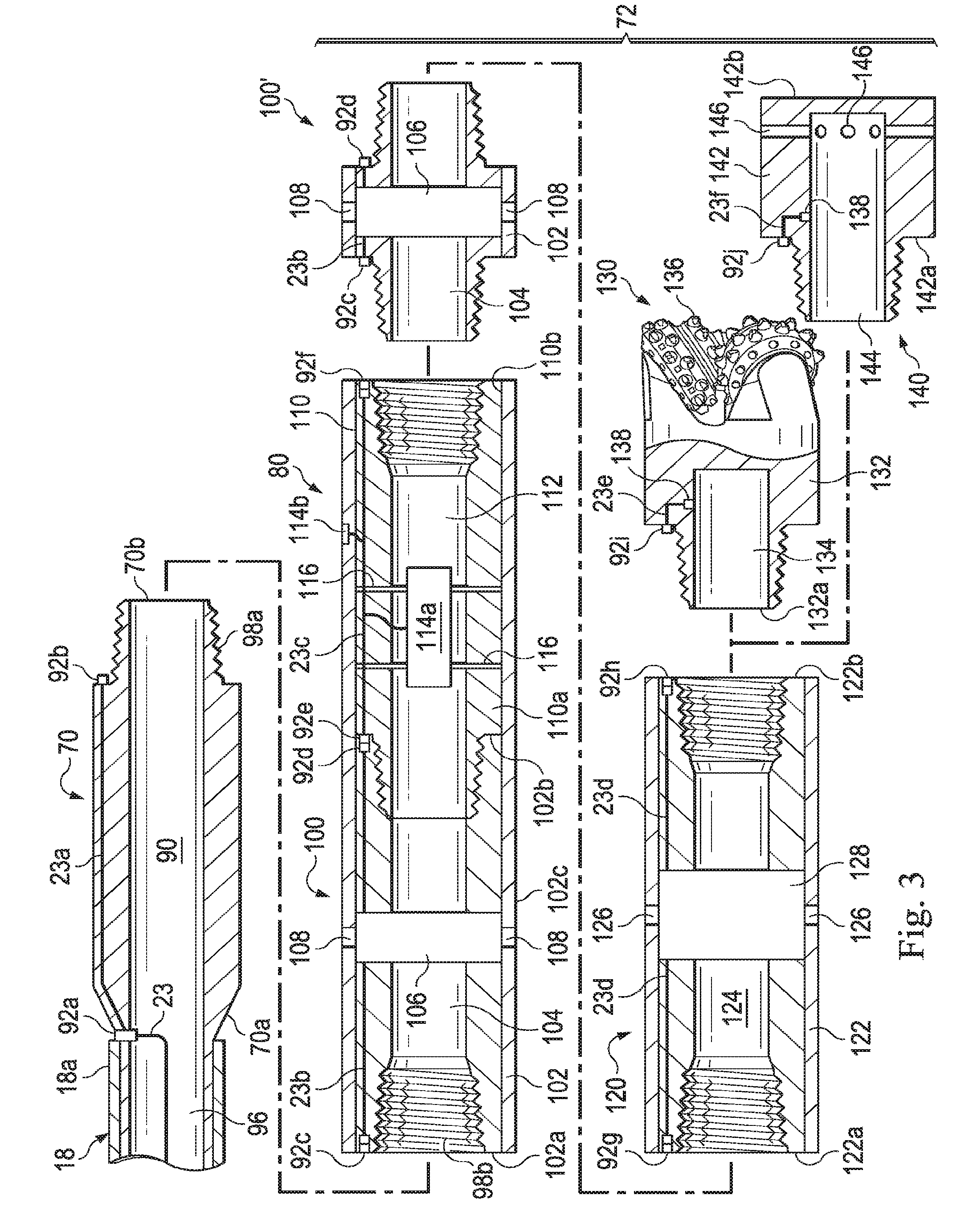
[0011] FIG. 3 is a depiction of a coiled tubing connector head and bottom hole assembly of FIGS. 1 and 2, including circulating subs and a treatment tool in the bottom hole assembly makeup;
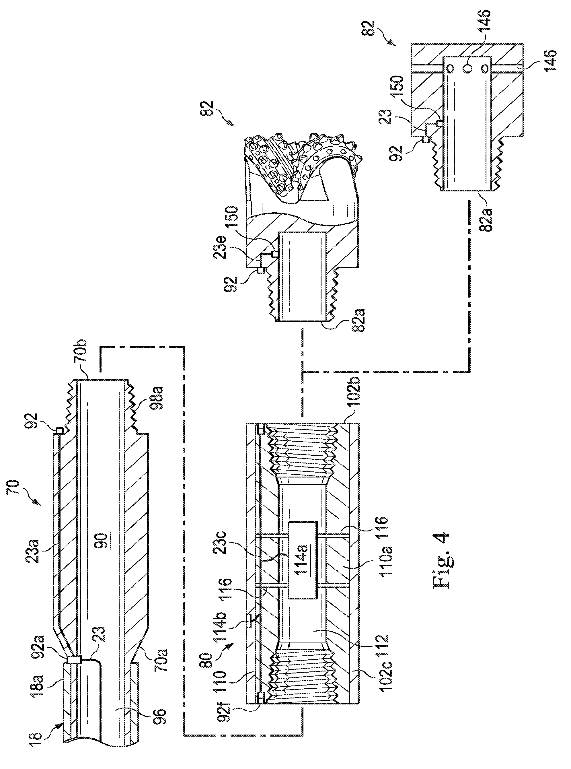
[0012] FIG. 4 is a depiction of a flow-through, coiled tubing connector head and a bottom hole assembly with a flow-through wireline tool and an intervention tool;
[0013] FIG. 5 is a depiction of a coiled tubing connector head and bottom hole assembly of FIGS. 1 and 2, including packers and a treatment tool;
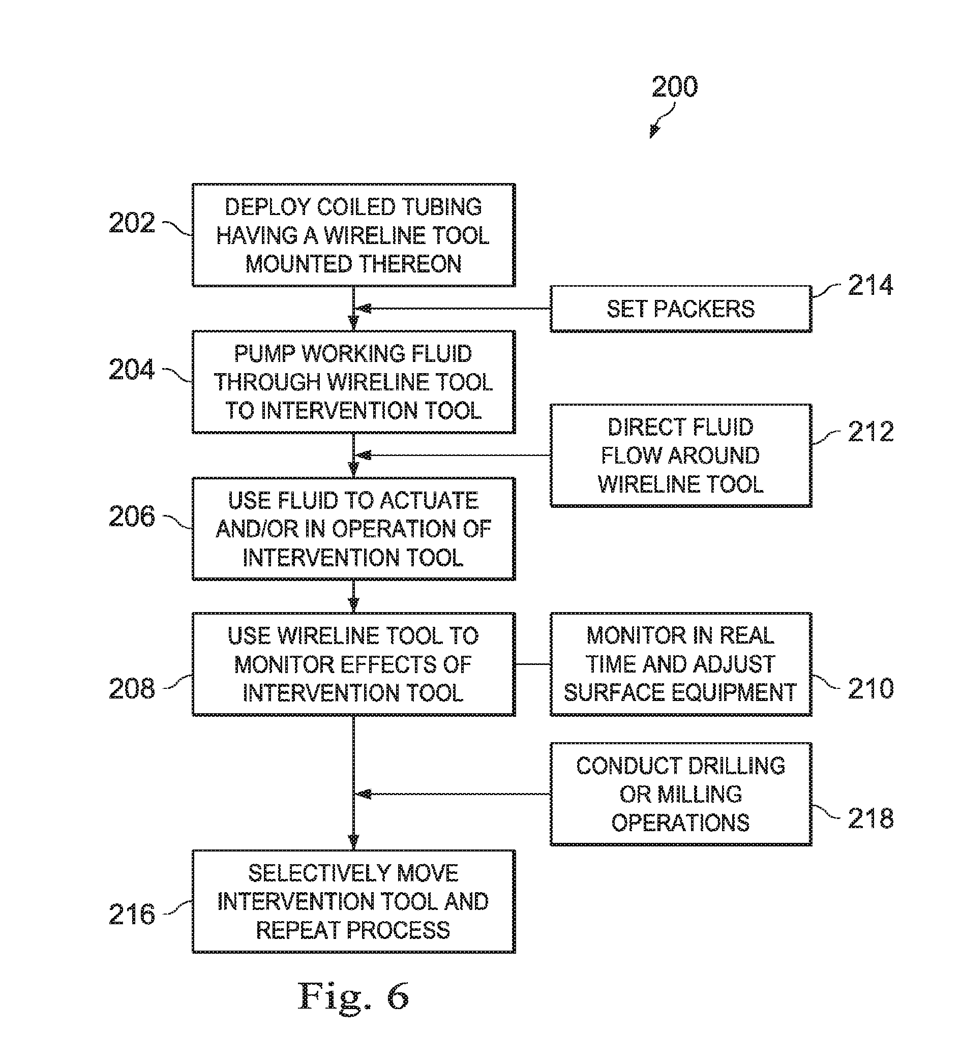
[0014] FIG. 6 illustrates embodiments of a method for conducting coiled tubing operations in a wellbore by combining a wireline tool with an intervention tool.
DETAILED DESCRIPTION OF THE DISCLOSURE
[0015] The disclosure may repeat reference numerals and/or letters in the various examples or figures. This repetition is for the purpose of simplicity and clarity and does not in itself dictate a relationship between the various embodiments and/or configurations discussed. Further, spatially relative terms, such as beneath, below, lower, above, upper, uphole, downhole, upstream, downstream, and the like, may be used herein for ease of description to describe one element or feature's relationship to another element(s) or feature(s) as illustrated, the upward direction being toward the top of the corresponding figure and the downward direction being toward the bottom of the corresponding figure, the uphole direction being toward the surface of the wellbore, the downhole direction being toward the toe of the wellbore. Unless otherwise stated, the spatially relative terms are intended to encompass different orientations of the apparatus in use or operation in addition to the orientation depicted in the figures. For example, if an apparatus in the figures is turned over, elements described as being "below" or "beneath" other elements or features would then be oriented "above" the other elements or features. Thus, the exemplary term "below" can encompass both an orientation of above and below. The apparatus may be otherwise oriented (rotated 90 degrees or at other orientations) and the spatially relative descriptors used herein may likewise be interpreted accordingly.
[0016] Moreover, even though a figure may depict a horizontal wellbore or a vertical wellbore, unless indicated otherwise, it should be understood by those skilled in the art that the apparatus according to the present disclosure is equally well-suited for use in wellbores having other orientations including, deviated wellbores, multilateral wellbores, or the like. Likewise, unless otherwise noted, even though a figure may depict an offshore operation, it should be understood by those skilled in the art that the apparatus according to the present disclosure is equally well-suited for use in onshore operations and vice-versa.
[0017] Generally, a coiled tubing universal connector head has a flow through bore and an electrical and/or optical cable connector that mates with a cable connector of a bottom hole assembly having at least an analytic tool and an intervention tool, thereby permitting traditional wireline measurements and monitoring to be carried out during the same run or trip as wellbore intervention activities. In this regard, the cable connector of the universal connector head mates with a cable connector of a circulating sub. The circulating sub has a flow through bore and a cable connector that mates with a cable connector of the analytic tool. The analytic tool is a wireline sub having a housing with sensors positioned along an inner flow through bore of the housing so that flow can move past the wireline tool when desired. The sensors are electrically and/or optically connected to the cable connector of the analytic tool in order to communicate via a cable extending down through the coiled tubing. Attached below the analytic tool is intervention tool such as a jetting tool for perforating or a drill bit for milling or drilling. The circulating sub has a bypass valve that can port fluid around the analytic tool as desired to avoid subjecting sensors of the analytic tool to certain fluids, such as corrosive fluids or sand slurries that could otherwise damage the wireline sensor. Utilizing a flow though universal connector head and an analytic tool that is incorporated as part of the bottom hole assembly permits the elimination or reduction of multiple wellbore trips for a particular CT procedure.
[0018] Turning to FIGS. 1 and 2, shown is an elevation view in partial cross-section of a coiled tubing (CT) drilling and production system 10 utilized to produce hydrocarbons from wellbore 12 extending through various earth strata in an oil and gas formation 14 located below the earth's surface 16. Wellbore 12 may be formed of a single or multiple bores 12a, 12b, . . . 12n (illustrated in FIG. 2), extending into the formation 14, and disposed in any orientation, such as the horizontal wellbore 12b illustrated in FIG. 2.
[0019] Coiled tubing drilling and production system 10 generally utilizes coiled tubing 18 to conduct various drilling and production operations. Coiled tubing 18 is characterized by a distal end 18a and includes an inner annulus or flowbore 19. The coiled tubing 18 is stored on a spool or reel 20 assembly (e.g., by being wrapped about the reel) positioned adjacent a wellhead 21. A tube guide 22 guides the coiled tubing 18 into an injector 24 supported on a frame assembly 25 and positioned above wellhead 21, and is used to feed and direct the coiled tubing 18 into and out of the wellbore 12. The injector 24 and frame assembly 25 may be suspended by a conventional derrick (not shown) or crane 28. As used herein the term "coiled tubing" will include any continuous or endless pipe string that may be wound on a spool or otherwise deployed rapidly including continuous metal tubulars such as low-alloy carbon-steel tubulars, composite coiled tubulars, capillary tubulars and the like.
[0020] The coiled tubing 18 extends through a blowout preventer stack 26 connected to wellhead 21 for pressure control of wellbore 12. Positioned atop the BOP stack 26 is lubricator mechanism or stuffing box 27 which provides the primary operational seal about the outer diameter of the coiled tubing 18 for the retention of any pressure that may be present at or near the surface of the wellbore 12. Although a land-based coiled tubing system is depicted in FIG. 1, coiled tubing 18 can be deployed from floating rigs, jackups, platforms, subsea wellheads, or any other well location.
[0021] For offshore operations, as shown in FIG. 2, CT drilling and production system 10 may be mounted on an oil or gas platform 44, such as the offshore platform as illustrated, semi-submersibles, drill ships, and the like (not shown). Although system 10 of FIG. 2 is illustrated as being marine-based, system 10 of FIG. 2 may be deployed on land. Likewise, although system 10 of FIG. 1 is illustrated as being land-based, system 10 of FIG. 1 may be deployed offshore. In any event, for marine-based systems, one or more subsea conduits or risers 46 extend from deck 50 of platform 44 to a subsea wellhead 21. Coiled tubing 18 extends down from platform 44, through subsea conduit 46 and BOP 26 into wellbore 12.
[0022] A working or service fluid source 48, such as a storage tank or vessel, may supply a working fluid 50 to coiled tubing 18. In particular, fluid source 48 is in fluid communication with a fluid swivel 52 secured to reel 20 and in fluid communication with the interior of coiled tubing 18. Working fluid source 48 may supply any fluid utilized in CT operations, including without limitation, drilling fluid, cementious slurry, acidizing fluid, liquid water, steam or some other type of fluid. Various examples of fluids that may be provided by fluid source 48 and employed in the drilling and production operation described herein include air, water, oil, lubricant, friction reducer, natural gas, mist, foam, surfactant, nitrogen, various gases, drilling mud, acid, etc., or any combination thereof, which are flowed through the coiled tubing 18 during a downhole operation. Moreover fluid source 48 may be disposed to provide the working fluid at a select pressure, such as high pressure pumping operation, or may be utilized to adjust the pressure of the pumped fluid. Fluid source 48 may likewise be in communication with other surface equipment 49, such as mixers, blenders and the like, utilized to prepare fluids for pumping downhole via fluid source 48. In preferred embodiments, fluid source 48 and/or surface equipment 49 may be adjustable in real time responsive to communications during various CT operations from wellbore 12 as described below.
[0023] The CT drilling and production system 10 may also include a power supply 54 and a communications hub 56 for sending signals and/or power and otherwise controlling the CT operations via electric and/or optic cable 23 deployed within coiled tubing 18.
[0024] CT drilling and production system 10 may generally be characterized as having a pipe system 58. For purposes of this disclosure, pipe system 58 may include casing, risers, tubing, drill strings, completion or production strings, subs, heads or any other pipes, tubes or equipment that couples or attaches to the foregoing, such as coiled tubing 18, conduit 46, collars, and joints, as well as the wellbore 12 and laterals in which the pipes, casing and strings may be deployed. In this regard, pipe system 58 may include one or more casing strings 60 that may be cemented in wellbore 12, such as the surface, intermediate and production casings 60 shown in FIG. 1. An annulus 62 is formed between the walls of sets of adjacent tubular components, such as concentric casing strings 60 or the exterior of coiled tubing string 18 and the inside wall 62 of wellbore 12 or casing string 60, as the case may be.
[0025] A universal CT connector head 70 having one or more cable connectors or terminals (not shown) is attached to the distal end 18a of the coiled tubing 18. A bottom hole assembly (BHA) 72 having one or more cable connectors or terminals (not shown) is likewise attached to connector head 70 to permit BHA 72 to be suspended from coiled tubing 18. CT drilling and production system 10 is utilized to pass a fluid down the flowbore 19 of the coiled tubing 18, through connector head 70 to bottom hole assembly 72. The return fluid will then pass up the annulus 62 formed between coiled tubing 18 and casing string 60 (or inside wall 62 if uncased). Fluids, cuttings and other debris returning to surface 16 from wellbore 12 are directed by a flow line 74 to storage tanks 76 (or fluid source 48) and/or processing systems 78, such as shakers, centrifuges and the like.
[0026] BHA 72 generally includes at least one analytic tool 80 and at least one intervention tool 82. In one or more embodiments, the analytic tool 80 is positioned between the connector head 70 and the intervention tool 82. It will be appreciated that in many cases, because of the nature of the tool function (such as milling or drilling), the intervention tool 82 must be positioned at the distal end 72a of the BHA 72. As used herein, analytic tool 80 refers to any type of sensor, observation or measurement device that can be utilized to monitor a condition of the wellbore 12, wellbore fluid or surrounding formation 14. Non-limiting examples of analytic tools 80 include casing collar locators, cement bond tools, cement bond tools, sonic and ultrasonic tools, accelerometers, resistivity tools, nuclear tools, gamma ray tools, flow meters, calipers, cameras, integrated computational elements, fiber optic sensors (such as distributed acoustic sensors), and the like. As used herein, intervention tool 82 refers to any type of tool that modifies the wellbore or materials within it. Non-limiting examples of intervention tools include drill bit, a milling bit, a cleaning tool, a stimulation tool, a fishing tool, a recovery tool, perforating tool, jetting tool, pipe cutters, settable plugs and packers, downhole valves, and the like.
[0027] BHA 72 may also include at least one circulating sub 83. In one or more embodiments, BHA 72 may include at least a first circulating sub 83a between the analytic tool 80 and the connector head 70 and a second circulating sub 83b between the analytic tool 80 and the intervention tool 82. In some embodiments, circulating sub 83a is positioned between the connector head 70 and the analytic tool 80 in order to selectively port a working fluid 50 from the inner bore 19 of coiled tubing 18 to the annulus 62 so as to avoid damage to the analytic tool 80 during certain operations. In one or more embodiments, BHA 72 may include an additional pass-through treatment tool 84, such as a jetting tool or clean out tool.
[0028] Turning to FIG. 3, connector head 70 and BHA 72 are illustrated in more detail. As shown, connector head 70 is attached to the distal or free end 18a of coiled tubing 18. Except as set forth below, it will be appreciated that connector head 70 is not limited to a particular type of connector head and may be secured to the coiled tubing 18a utilizing any known method of attachment. In this regard, connector head includes a through bore 90 extending from a first end 70a of connector head 70 to a second end 70b to allow fluid (not shown) flowing through coiled tubing 18 to pass to BHA 72. In this regard, connector head 70 is a flow through connector. Connector head further includes at least one cable connector 92 in electrical and/or optical communication with an electrical and or optical cable 23 extending down coiled tubing 18 from the surface 16. In some embodiments, cable 23 is a hybrid cable, comprised of both optical fiber and electrical conductors. In the illustrated embodiment, a first cable connector 92a is illustrated at the first end 70a of connector head 70 and a second cable connector 92b is illustrated at the second end 70b of connector head 70. In other embodiments, cable connector 92a may be eliminated so that cable 23 is directly in communication with cable connector 92b. In preferred embodiments, cable 23 extends down from the surface 16 through the interior 96 of coiled tubing 18. Although cable 23 may be only an electric cable or an optical cable is some embodiments, in other embodiments, cable 23 is an electro/optic cable formed of both optical fibers and electrical conducing wire. Cable 23 may include a cable segment 23a between cable connectors 92a and 92b.
[0029] Second end 70b of connector head 70 may include any type of engagement mechanism 98 for attaching adjacent tubulars to one another. Thus, non-liming examples of engagement mechanisms would be traditional threaded box and pin type joints. In the illustrated example, second end 70b is a threaded pin 98a for receipt of a threaded box 98b. Although threads are described as the engagement mechanism for attaching adjacent tubulars, other types of engagement mechanisms may be utilized for attaching adjacent tubulars and equipment, such as interference fit, splines, pins or fasteners, and persons of ordinary skill in the art will understand the disclosure is not limited to any particular type of joint or engagement mechanism, it being further understood that for tubulars or equipment interconnected in a string, such tubulars or equipment may have a first or upper engagement mechanism and a second or lower engagement mechanism.
[0030] In one or more embodiments, BHA 72 may include at least one circulating sub 100. Although circulating sub 100 may be included anywhere along the length of BHA 72 as needed for a particular CT operation, in the illustrated embodiment, circulating sub 100 may be attached to second end 70b of connector head 70. Generally, circulating sub 100 is formed of a tubular 102 having a through bore 104 extending from a first tubular end 102a to a second tubular end 102b. Positioned along through bore 104 is a valve 106 movable between a first position and a second position, whereby in the first position, valve 106 permits fluid communication between the first and second tubular ends 102a, 102b, while in a second position, valve 106 permits fluid communication between the first end 102a and one or more ports 108 formed along tubular 102. It will be appreciated that in the second position, valve 106 blocks fluid communication between the first and second tubular ends 102a, 102b, but rather, directs flow from coiled tubing 18 to the exterior 102c of tubular 102. In other embodiments, in the second position valve 102 may direct flow into bypass channels or conduits formed in or carried by tubular 102 and/or tubular 110 (as discussed below) and that will allow flow from coiled tubing 18 to bypass select subs downstream of circulating sub 100 without directing the flow to the exterior 102c of tubular 102.
[0031] In any event, circulating sub 100 further includes a cable connector 92c at the first end 102a and a cable connector 92d at the second end 102b, cable connectors 92c and 92d being linked by cable segment 23b. When circulating sub 100 is attached to second end 70b of connector head 70, cable connector 92c of circulating sub 100 mates with cable connector 92b of connector head 70 and through bore 104 is in fluid communication with through bore 90.
[0032] In one or more embodiments, valve 106 may be mechanically actuated by various mechanisms known in the art, such as by pumping an object, ball or dart through coiled tubing 18 from surface 16 to seat in valve 106, driving it from one position to the other position. Likewise, and increase in pressure or pressure signals from the surface 16 may be utilized to actuate valve 106.
[0033] In other embodiments, because cable 23 is in place, an electric or optic signal from the surface may be utilized to actuate valve 106. In the case of an electric signal, it will be appreciated that valve 106 may be an electric valve that can be repeatedly driven between the first and second position, permitting the valve 106 to be selectively opened and closed during various procedures.
[0034] In one or more embodiments, BHA 72 may include a second circulating sub 100' (see FIG. 3) positioned below analytic tool 80 in order to direct fluid flow back into a through bore of the BHA 72, thereby permitting the working fluid to be utilized in coiled tubing operations below the analytic tool 80.
[0035] BHA 72 includes at least one analytic tool 80. Although analytic tool 80 may be included anywhere along the length of BHA 72 as needed for a particular CT operation, in the illustrated embodiment, analytic tool 80 may be attached to second end 102b of circulating sub 100. However, it will be appreciated that in some embodiments, circulating sub 100 may not be included in BHA 72, in which case, analytic tool 80 may attach to the second end 70b of connector head 70. In any event, analytic tool 80 is formed of a tubular 110 having a through bore 112 extending from a first tubular end 110a to a second tubular end 110b. Positioned along tubular 110 are one or more analytic sensors 114 of the type traditionally carried on a wireline tool. Depending on the type of data to be acquired by sensor 114, sensor 114 may be positioned along through bore 112, such as sensor 114a, or may be positioned along the external surface 110c of tubular 110, such as sensor 114b, or both. Although sensor 114 requires an electric or optic connection to cable 23, sensor 114 is not otherwise limited to a particular type of sensor. In one or more embodiments, sensor 114 may be casing collar locators, cement bond tools, cement bond tools, sonic and ultrasonic tools, accelerometers, resistivity tools, nuclear tools, gamma ray tools, flow meters, spinners, calipers, cameras, integrated computational elements, or fiber optic sensors. In one or more embodiments, sensor 114a is centrally located along through bore 112. In this regard, analytic tool may include a centralizer 116 to position sensor 114a more centrally in the flow path through analytic tool 80.
[0036] Analytic tool 80 further includes a cable connector 92e at the first end 110a Cable connector 92e is connected to cable segment 23c so as to provide electrical and/or optic connection to sensor 114. In one or more embodiments, analytic tool 80 may also include a cable connector 92f at the second end 110b, cable connectors 92e and 92f being linked by cable segment 23c. When analytic tool 80 is attached to second end 102b of circulating sub 100, cable connector 92d of circulating sub 100 mates with cable connector 92e of analytic tool 80 and through bore 104 is in fluid communication with through bore 112.
[0037] It will be appreciated that with a flow through connector head 70 and a flow through analytic tool 80, various CT operations requiring a working fluid, such as perforating, drilling or milling can be carried out in a wellbore 12 while at the same time collecting analytic data utilizing analytic tool 80.
[0038] BHA 72 includes at least one intervention tool 82. In one or more embodiments, intervention tool 82 may be a treatment or stimulation tool 120. Treatment or stimulation tool 120 is formed of a tubular 122 having a bore 124 extending from a first tubular end 122a at least partially through tubular 122 towards a second tubular end 122b. In some embodiments, bore 124 extends fully through tubular 122 between the two ends 122a, 122b. One or more ports 126 are positioned along tubular 124 and may communicate with bore 124 to inject a treatment fluid (not shown) from bore 124 into a wellbore (not shown) during CT operations.
[0039] Although some embodiments need not include electrical and/or optic connectivity of stimulation tool 120, in other embodiments, stimulation tool 120 further includes a cable connector 92g at the first end 122a. Cable connector 92g is connected to cable segment 23d so as to provide electrical and/or optic connection to stimulation tools 120 as needed. For example, in some embodiments, stimulation tool 120 may include an electric valve or sleeve 128 actuated to selectively open and close ports 126. In one or more embodiments, stimulation tool 120 may also include a cable connector 92h at the second end 122b, cable connectors 92g and 92h being linked by cable segment 23d. When stimulation tool 120 is attached to second end 110b of analytic tool 80, cable connector 92g of stimulation tool 120 mates with cable connector 92f of analytic tool 80 and bore 124 is in fluid communication with through bore 112.
[0040] In one or more embodiments, intervention tool 82 may be drill bit 130 positioned at the distal end 72a of BHA 72. Drill bit 130 is formed of a housing 132 and may include a bore 134 extending from a first housing end 132a at least partially through housing 132 towards a second housing end 132b. Drill bit 130 also includes cutting elements 136. Drill bit 130 is not limited to a particular type of drill bit. In this regard, cutting elements 136 may be fixed or movable. Likewise drill bit 130 may be rotating (in conjunction with a mud motor (not show) or operable based on fluid flow from coiled tubing 18.
[0041] Although some embodiments need not include electrical and/or optic connectivity of drill bit 130, in other embodiments, drill bit 130 further includes a cable connector 92i at the first end 132a. Cable connector 92i is connected to cable segment 23e so as to provide electrical and/or optic connection to drill bit 130 as needed. For example, in some embodiments, drill bit 130 may include an electric or optic sensor 138 for measuring a condition of the drill bit 130, working fluid or environment around the drill bit 130.
[0042] In some embodiments, treatment tool 120 is disposed between analytic tool 80 and drill bit 130, in which case treatment tool 120 is a flow-through tool with an inner bore 124 in fluid communication with the bore 134 of drill bit 130. Although drill bit 130 is illustrated as being attached to treatment tool 120, it will be appreciated that drill bit 130 can be likewise attached to analytic tool 80 or any other tool or sub, as desired for a particular CT procedure. As illustrated, when drill bit 130 is attached to second end 122b of stimulation tool 120, cable connector 92h of stimulation tool 120 mates with cable connector 92i of drill bit 130 and bore 124 is in fluid communication with bore 134.
[0043] In one or more embodiments, intervention tool 82 may be a perforating tool 140 positioned at the distal end 72a of BHA 72. Although not limited to a particular type of perforating tool, in one or more embodiments, perforating tool 140 may be of the hydro-jet or gun type. In the illustrated embodiment, perforating tool 140 is generally illustrated as a hydro-jet type, wherein high pressure, high velocity fluid, either alone or in combination with particulate, is utilized to render holes in casing (not shown). In such case, perforating tool 140 is formed of a housing 142 and may include a bore 144 extending from a first housing end 142a at least partially through housing 142 towards a second housing end 142b. Perforating tool 140 also includes jets 146 in fluid communication with bore 144 in order to deliver a high pressure, high velocity working fluid to a target (not shown), such as casing.
[0044] Although some embodiments need not include electrical and/or optic connectivity of perforating tool 140, in other embodiments, perforating tool 140 further includes a cable connector 92j at the first end 142a. Cable connector 92j is connected to cable segment 23f so as to provide electrical and/or optic connection to perforating tool 140 as needed. For example, in some embodiments, perforating tool 140 may include an electric or optic sensor 138 for measuring a condition of the perforating tool 140, working fluid or environment around the perforating tool 140.
[0045] Although perforating tool 140 is illustrated as being attached to stimulation tool 120, it will be appreciated that perforating tool 140 can be likewise attached to analytic tool 80 or any other tool or sub, as desired for a particular CT procedure. As illustrated, when perforating tool 140 is attached to second end 122b of stimulation tool 120, cable connector 92h of stimulation tool 120 mates with cable connector 92j of perforating tool 140 and bore 124 is in fluid communication with bore 144.
[0046] FIG. 4 illustrates that certain embodiments of BHA 72 are not limited to a particular arrangement so long as such embodiments of BHA 72 generally include an analytic tool 80 and an intervention tool 82. Thus, in FIG. 4, connector head 70 is attached to the distal or free end 18a of coiled tubing 18. In this regard, connector head includes a through bore 90 extending from a first end 70a of connector head 70 to a second end 70b to allow fluid (not shown) flowing through coiled tubing 18 to pass to BHA 72. In this regard, connector head 70 is a flow through connector. Connector head further includes at least one cable connector 92 in optical/electrical communication with a cable 23 extending down coiled tubing 18 from the surface 16. In the illustrated embodiment, a first cable connector 92a is illustrated at the first end 70a of connector head 70 and a second cable connector 92b is illustrated at the second end 70b of connector head 70. In other embodiments, cable connector 92a may be eliminated so that cable 23 is directly in communication with cable connector 92b. In preferred embodiments, cable 23 extends down from the surface 16 through the interior 96 of coiled tubing 18. Although cable 23 may be only an electric cable or an optical cable is some embodiments, in other embodiments, cable 23 is an electro/optic cable formed of both optical fibers and electrical conducing wire. Cable 23 may include a cable segment 23a between cable connectors 92a and 92b.
[0047] Shown attached to connector head 70 in FIG. 4 is analytic tool 80. Analytic tool 80 is formed of a tubular 110 having a through bore 112 extending from a first tubular end 110a to a second tubular end 110b. Positioned along tubular 110 are one or more analytic sensors 114 of the type traditionally carried on a wireline tool. Depending on the type of data to be acquired by sensor 114, sensor 114 may be positioned along through bore 112, such as sensor 114a, or may be positioned along the external surface 110c of tubular 110, such as sensor 114b, or both. Although sensor 114 requires an electric or optic connection to cable 23, sensor 114 is not otherwise limited to a particular type of sensor. In one or more embodiments, sensor 114 may be casing collar locators, cement bond tools, cement bond tools, sonic and ultrasonic tools, accelerometers, resistivity tools, nuclear tools, gamma ray tools, flow meters, spinners, calipers, cameras, integrated computational elements, or fiber optic sensors. In one or more embodiments, sensor 114a is centrally located along through bore 112. In this regard, analytic tool may include a centralizer 116 to position sensor 114a more centrally in the flow path through analytic tool 80.
[0048] Analytic tool 80 further includes a cable connector 92e at the first end 110a. Cable connector 92e is connected to cable segment 23c so as to provide electrical and/or optic connection to sensor 114. In one or more embodiments, analytic tool 80 may also include a cable connector 92f at the second end 110b, cable connectors 92e and 92f being linked by cable segment 23c. When analytic tool 80 is attached to second end 70b of connector head 70, cable connector 92b of connector head 70 mates with cable connector 92e of analytic tool 80 and through bore 90 is in fluid communication with through bore 112.
[0049] Shown attached to analytic tool 80 in FIG. 4 is intervention tool 82 as described above. Although some embodiments need not include electrical and/or optic connectivity of intervention tool 82, in other embodiments, intervention tool 82 further includes a cable connector 92 at the first end 82a. Cable connector 92 is connected to cable segment 23 so as to provide electrical and/or optic connection to intervention tool 82 as needed. For example, in some embodiments, intervention tool 82 may include an electric or optic sensor 150 for measuring a condition of the intervention tool 82, working fluid or environment around the intervention tool 82.
[0050] Turning to FIG. 5, another configuration of BHA 72 is illustrated in which one or more packers 170 are incorporated into BHA 72. In certain CT operations, such as acidizing, it is desirable to isolate other BHA 72 components, such as the analytic tool 80, from the zone of treatment in order to ensure the treatment fluid does not damage such other components. Although the disclosure is not limited to a particular type of packer, each packer 170 may generally include a packer housing 172 having a first end 172a and a second end 172b with a through bore 174 extending between the first and second ends 172a, 172b. Packer 170 includes one or more seal elements 176 that may be actuated to seal the annulus (not shown) around packer 170. In one or more embodiments, seal elements 176 are elastomeric. Packer 170 further includes an actuation mechanism 178 to urge seal elements 176 into a sealing condition. Although actuation mechanism 178 is not limited to a particular type of mechanism, in one or more embodiments, actuation mechanism 178 may be electrically operated utilizing cable 23 extending through coiled tubing 18. Such an arrangement is desirable because this allows actuation mechanism 178, and thus seal elements 176, to be selectively set and unset as the BHA 72 is moved along a wellbore (not shown). It is the electrical connectivity of packers 170 that permits this in such embodiments.
[0051] In this regard, packer 170 further includes a cable connector 92k at the first end 172a. Cable connector 92k is connected to cable segment 23m so as to provide electrical and/or optic connection to actuation mechanism 178. In one or more embodiments, packer 170 may also include a cable connector 92l at the second end 172b, cable connectors 92k and 92l being linked by cable segment 23g. When packer 170 is attached to the second end of and adjacent sub or tool, the cable connector 92 of the adjacent sub mates with cable connector 92k of packer 170 and through bore 174 is in fluid communication with the through bore of the adjacent sub.
[0052] Also shown in FIG. 5 is a mud motor tool 180 for use in various CT operations. Persons or ordinary skill in the art will appreciate that mud motor tool 180 may serve a variety of purposes, such as providing rotational power to an intervention tool 82 or for local electricity production. In any event, mud motor tool 180 is not limited to a particular type or configuration, but may generally include a housing 182 having a through bore 184 extending between a first end 182a and a second end 182b. A mud motor 186 is positioned along through bore 184 and is operable as is well known in the art.
[0053] Although some embodiments need not include electrical and/or optic connectivity of mud motor tool 180, in other embodiments, motor tool 180 further includes a cable connector 92m at the first end 182a. Cable connector 92m is connected to cable segment 23h so as to provide electrical and/or optic connection to motor tool 180 as needed. For example, in some embodiments, mud motor tool 180 may include an electric or optic sensor 138 for measuring a condition of the mud motor tool 180, working fluid or environment around the motor tool 180. Mud motor tool 180 may also include a cable connector 92n at the second end 182b, which cable connector 92n is connected to cable segment 234h so as to provide connectivity to a tool or sub downstream of mud motor tool 180, such as intervention tool 82 as described herein.
[0054] While FIGS. 1-5 illustrated various tools and subs of the BHA 72, other than the certain intervention tools, such as drill bits, that necessarily must be at the distal end 72a of BHA 72, the disclosure is not limited to a particular arrangement of the tools and subs. It will be appreciated that the connectors 92 and wire segments 94 and through bore of the analytic tool permit both fluidic connectivity and electrical and/or optical connectivity that has not heretofore existed for coiled tubing arrangements. This connectivity permits standard wireline type of monitoring to occur in the same run as various intervention activities, eliminating or reducing the need for separate run-ins for wireline monitoring and for intervention activities. Moreover, the fluidic and electrical and/or optical connectivity permit the various tools and subs to be arranged in a variety of configurations as desired for a particular CT operation. Thus, in some embodiments, the BHA is not limited to a particular arrangement of the analytic tool with other tools and sub so long as the above-described fluidic and electric/optical connectivity as needed for a particular CT operation is available.
[0055] Turning to FIG. 6, a coiled tubing operation 200 is illustrated. This method 200 of conduct operations in a wellbore generally begins in a first step 202 of deploying a wireline tool secured to coiled tubing into a wellbore. It should be noted in this regard that the wireline tool may be any analytic tool as described herein, or as readily understood by persons of ordinary skill in the art. Moreover, unlike the general practice of the prior art of hanging the wireline tool on a cable extending through the coiled tubing, in step 202 the wireline tool is rigidly fixed to the coiled tubing as part of the BHA so that the wireline tool is supported by the coiled tubing. The operation 200 is not limited to any particular operation, but is generally a coiled tubing operation that in the prior art would require separate trips for running in a BHA or a wireline tool. In this regard, the operation 200 may be a wellbore stimulation operation.
[0056] In step 204, a first working fluid is pumped through the wireline tool to an intervention tool. More specifically, a working fluid is pumped down from the surface through the coiled tubing. The working fluid flows through the connector head. Unlike the prior art, the working fluid also flows through the wireline tool along a first flow path through the wireline tool.
[0057] In step 206, the first working fluid is utilized to actuate and/or in operation of an intervention tool suspended by the coiled tubing below the wireline tool. In this regard, the working fluid may be used to drive a drill bit for drilling into the formation or mill for cutting casing or to drive similar drilling or cutting equipment at the end of the BHA. The working fluid may alternatively or in addition thereto, be used by a jetting tool to perforate casing.
[0058] In step 208, the wireline tool is utilized to analyze or monitor a parameter or characteristic of the coiled tubing operation or to otherwise make measurements related thereto. It will be appreciated that the wireline tool, and hence, the acquisition of data occurs while the intervention equipment remains in the wellbore along with the wireline tool. For example, in stimulation operations, the wireline tool may be utilized to make a measurement in the wellbore prior to, during and/or after stimulation. In this regard, because the wireline tool is deployed in the wellbore with the stimulation tool, the effects of stimulation can be monitored in real-time as the chemical treatment is being pumped into the wellbore. Moreover, because the first working fluid is being pumped along a path through the wireline tool, the wireline tool may be utilized to measure, monitor or analyzed the first fluid as it flows through the wireline tool.
[0059] In step 210, a parameter of the wellbore is measured in real-time as a CT operation is occurring, and based on the measured parameter, the CT operation may be adjusted on the fly to achieve a desired result. In this regard, because the wireline tool is incorporated in the BHA but also in real-time communication with the surface and surface equipment, various surface equipment involved in the CT operation can be automatically adjusted in real time based on the measured parameter. Thus, for example, pressures, injection rates, and compositions of working fluid in hydraulic fracturing or stimulation operations may be adjusted in real time to achieve a desired result. Pumps may be adjusted. Blenders or mixers may be adjusted, or the amount of solid or particulate material utilized in the operation may be altered.
[0060] In step 212, a circulating valve may be actuated to direct a second working fluid along a second flow path around the wireline tool, and thereafter, the second working fluid may be pumped along the second flow path. It will be appreciated that in certain operations, abrasive or corrosive fluid may be pumped through the coiled tubing which fluid could damage the sensors of the wireline tool. Thus, in step 212, the flow of a second working fluid that could damage the wireline tool bypasses the wireline tool (as opposed to pumping the second working fluid through the wireline tool), and hence measurements, analysis or monitoring by the wireline tool may be suspended during pumping of the second fluid. A circulating valve positioned in the BHA upstream of the wireline tool, between the wireline tool and the connector head, can be utilized to direct flow when such fluids are being pumped. Thereafter, once pumping of the second working fluid is suspended or complete, the circulating valve may be actuated to close the bypass and re-establish flow through the wireline tool, after which, the first fluid or another fluid may be pumped along the first flow path and use of the wireline tool may continue. The bypass may be direct the second fluid flow to the annulus of the wellbore or may direct fluid flow along another flow path so as to prevent the second fluid from damaging the sensors of the wireline tool. In one or more embodiments of step 212, a second circulating valve may be actuated to direct the second working fluid from the second flow path back to a location along the BHA below the wireline tool, thus permitting the second working fluid to be utilized for operations such as treatments and interventions occurring below the wireline tool. The circulating valve may be activated utilizing a signal from the surface transmitted on the cable extending through the coiled tubing and BHA. In this way, the circulating valve may be selectively operated multiple times as the BHA is moved to different locations. For example, the signal may actuate a valve driving it to a closed configuration in order to cause the valve to divert fluid flow from the first flowpath to the second flowpath. Thereafter, a signal may actuate the valve driving it to an open configuration so as to permit flow along the first flowpath.
[0061] In step 214, one or more packers carried by the coiled tubing may be set in order to isolate a wellbore zone for a particular operation, such as acidizing or hydraulic fracturing. While in some embodiments the packers may be mechanically set by dropping or pumping an object such as a ball or dart down the coiled tubing, in other embodiments, the packers may be activated utilizing a signal from the surface transmitted on the cable extending through the coiled tubing and BHA. In this way, the packers may be selectively set and released multiple times. For example, in one or more embodiments, the coiled tubing is utilized to position the BHA in a desired location, after which, the packers may be set to isolate a particular production zone for receipt of a treatment, such as acidizing or hydraulic fracturing. Thereafter, the packers may be released and the BHA may be moved to a second location, after which the packers may be set to isolate a second production zone. This procedure may be carried out multiple times. Significantly, prior to, during and/or after each treatment, the wireline tool may be utilized to evaluate the treatment and adjustments to the treatment may be made to achieve a desired result. While the step is not limited to a particular tool utilized in the treatment or operation, in one or more embodiments, a treatment tool such as a jetting tool may be carried on the BHA between two packers, while the wireline tool may be carried on the BHA above or below the two packers.
[0062] In step 216, a treatment of the wellbore may be performed utilizing a treatment tool carried by the coiled tubing as part of the BHA. While in some embodiments the treatment tool may be mechanically set by dropping or pumping an object such as a ball or dart down the coiled tubing, in other embodiments, the treatment tool may be activated utilizing a signal from the surface transmitted on the cable extending through the coiled tubing and BHA. In this way, the treatment tool may be selectively operated multiple times as the BHA is moved to different locations. For example, the signal may actuate a valve driving it to an open configuration in order to cause the treatment tool to inject a treatment fluid into a production zone to be treated. Thereafter, a signal may actuate the valve driving it to a closed configuration so as to stop the treatment and allow the BHA to be moved to a new location. In any event, as part of the treatment, fluid may be pumped through or around the wireline tool and the wireline tool may be utilized to evaluate the treatment in real time as desired.
[0063] In step 218, a milling, drilling, cutting or perforating may be performed by an intervention tool in the wellbore below the wireline tool. As part of the procedure, a working fluid may be pumped from the coiled tubing through the wireline tool to actuate the intervention tool. In one or more embodiments, such actuation may be via a mud motor tool incorporated in the BHA, it being understood that the working fluid drives the mud motor tool which in turn may power the intervention tool. During this procedure, the wireline tool may be utilized to evaluate the mechanical intervention in real time as desired. Additionally, sensors that may be incorporated in the intervention tool may likewise be utilized to evaluate the mechanical intervention or the intervention tool in real time since the intervention tool may be electrically and/or optically connected via the BHA to the surface. It will be appreciated that to the extent the coiled tubing is urging a intervention tool along the wellbore, during such operations, the packers will not be set. Once the procedure is complete for a section of the wellbore, packers may be set and a treatment tool may be actuated as described herein.
[0064] Thus, a bottom hole assembly for coiled tubing operations has been described. Embodiments of the bottom hole assembly may generally include a coiled tubing connector head having a tubular body with a through bore and at least one cable connector; an analytic tool secured to the connector head, the analytic tool having a through bore and an analytic tool cable connector mated with the cable connector of the connector head; and an intervention tool secured to the analytic tool. Other embodiments of a bottom hole assembly may generally include a coiled tubing connector head having a tubular body with a first end and a second end, a pass through bore extending between the two ends and at least one cable connector at the second end; an analytic tool secured to the connector head, the analytic tool having a first end and a second end, a pass through bore extending along an axis between the two ends with a centralizer supporting a sensor mechanism along the analytic tool bore, an analytic tool cable connector mated with the cable connector of the connector head; and an intervention tool secured to the analytic tool, the intervention tool having a first end and a second end, and a bore extending from the first end, wherein the bore of the intervention tool is in fluid communication with the bore of the analytic tool. Likewise, a coil tubing system for performing operations in a wellbore has been described. Embodiments of the coil tubing system may generally include coiled tubing forming an inner flow bore and having a distal end; a hybrid cable deployed in the inner flow bore of the coiled tubing, the cable including at least one fiber optic and one electric conductor; a connector head attached to the distal end of the coiled tubing, the connector head having at least one cable connector optically coupled to the fiber optic cable; an analytic tool secured to the connector head, the analytic tool having an first analytic tool cable connector mated with the cable connector of the connector head; and a first intervention tool secured to the analytic tool.
[0065] Any of the foregoing embodiments, may include any one of the following elements, alone or in combination with each other: [0066] The analytic tool is selected from the group consisting of setting tools, gamma perforating tools, casing collar locators, cement bond tools, cement bond tools, sonic and ultrasonic tools, resistivity tools, nuclear tools, natural gamma ray tools, flow meters. [0067] The intervention tool is selected from the group consisting of a drill bit, a milling bit, a cleaning tool, a stimulation tool, a fishing tool, a recovery tool, perforating tool, jetting tool, pipe cutters, settable plugs and packers, or downhole valves. [0068] The analytic tool comprises an upper engagement mechanism at a first end of the analytic tool and a lower engagement mechanism at a second end of the analytic tool, wherein the upper engagement mechanism attaches to the engagement mechanism of the coiled tubing connector head and the lower engagement mechanism attaches to an engagement mechanism of the intervention tool. [0069] A circulating sub secured between the connector head and the analytic tool, the circulating sub comprising an elongated tubular having a first end and a second end with a through bore extending between the two ends, ports formed in the tubular and a valve mechanism to selectively alter fluid flow through the bore from the first end of the tubular to either the second end of the tubular or the ports, the circulating sub further having an upper circulating sub connector engaged with the cable connector and a lower circulating sub connector engaged with the analytic tool cable connector. [0070] The analytic tool has a first end and a second end and comprises a pass through bore extending along an axis between the two ends with a centralizer supporting a sensor mechanism along the analytic tool bore axis. [0071] A first circulating sub secured between the coiled tubing connector head and the analytic tool and a second circulating sub secured between the analytic tool and the intervention tool, the circulating subs in a first configuration permitting flow through the first circulating sub from the connector head, past the pass through bore in which the sensor mechanism is supported and to the intervention tool and a second configuration in which a first flow path from the first circulating sub bypasses the sensor mechanism and a second flow path from the second circulating sub passes through the bore in which the sensor mechanism is supported. [0072] A first circulating sub secured between the connector head and the analytic tool, the circulating sub having an elongated tubular with a first end and a second end and a through bore extending between the two ends, ports formed in the tubular and a valve mechanism to selectively alter fluid flow through the bore from the first end of the tubular to either the second end of the tubular or the ports, the circulating sub further having an first circulating sub connector mated with the cable connector of the connector head and a lower circulating sub connector mated with the analytic tool cable connector, wherein the through bores of the connector head, the circulating sub and the analytic tool are in fluid communication with one another. [0073] The hybrid cable further comprises at least one electric cable and the connector head comprises an electric cable connector electrically coupled to the electric cable. [0074] A first circulating sub secured between the connector head and the analytic tool, the circulating sub having an elongated tubular with a first end and a second end and a through bore extending between the two ends, ports formed in the tubular and an electric valve mechanism to selectively alter fluid flow through the bore from the first end of the tubular to either the second end of the tubular or the ports, the circulating sub further having an first circulating sub connector electrically connected to the electric valve mechanism, the first circulating sub connector mated with the cable connector of the connector head, and a second circulating sub connector electrically connected to the first circulating sub connector, the second circulating sub connector mated to the first analytic tool connector; and a treatment tool secured between the analytic tool and the first intervention tool, the treatment tool having an elongated tubular with a first end and a second end and a through bore extending between the two ends, ports formed in the tubular and an electric valve mechanism to selectively direct fluid flow from the through bore of the treatment tool to the ports of the treatment tool, the treatment tool further having a first treatment tool connector mated with the second analytic tool connector, the first treatment tool connector electrically connected to the electric valve mechanism of the treatment tool, wherein the through bores of the connector head, the circulating sub, the analytic tool, the treatment tool and the first intervention tool are in fluid communication with one another.
[0075] Thus, a method of conducting operations in a wellbore has been described. Embodiments of the method include utilizing coiled tubing to support and deploy a wireline tool into a wellbore; pumping a first fluid along a first flow path through the wireline tool supported on the coiled tubing; actuating a circulating valve to direct a second fluid along a second flow path around the wireline tool; and pumping a second fluid along the second flow path. Other embodiments of the method include utilizing coiled tubing to support and deploy a wireline tool into a wellbore; pumping a first fluid along a first flow path through the wireline tool to an intervention tool; and utilizing the first fluid to actuate an intervention tool supported below the wireline tool. Likewise, a method of conducting coiled tubing operations in a wellbore has been described and may include deploying in a single trip on coiled tubing into a wellbore a wireline tool and a intervention tool; pumping a first working fluid down the coiled tubing, through the wireline tool to the intervention tool; actuating the intervention tool suspended below the wireline tool utilizing the working fluid pumped through the wireline tool. Other embodiments of the method include deploying on coiled tubing into a wellbore a wireline tool and an intervention tool suspended below the wireline tool; pumping a first fluid along a first flow path through the wireline tool to the intervention tool; actuating a circulating valve to direct a second fluid along a second flow path around the wireline tool; and pumping a second fluid along the second flow path.
[0076] For the foregoing embodiments, the method may include any one of the following steps, alone or in combination with each other: [0077] Utilizing the wireline tool to make measurements while the first fluid is pumped along the first flow path; and suspending the measurements while the second fluid is pumped along the second flow path. [0078] Suspending pumping of the second fluid; actuating the circulating valve to direct a fluid flow along the first flow path; and continuing pumping of the first fluid along the first flow path through the wireline tool. [0079] Utilizing the intervention tool to perform a task selected from the group consisting of perforating wellbore casing, milling wellbore casing, drilling a wellbore and drilling a plug. [0080] Monitoring a condition or parameter of the wellbore utilizing the wireline tool. [0081] Monitoring occurs while a task is being performed by the intervention tool. [0082] Utilizing the intervention tool and the wireline tool simultaneously. [0083] Adjusting the mechanical intervention task in real time based upon monitoring by the wireline tool. [0084] Utilizing the BHA to inject a treatment fluid into the wellbore and utilizing the wireline tool to monitor the effects of the treatment on the wellbore in real time. [0085] Adjusting the wellbore treatment in real time during injection of a treatment fluid based on the monitoring by the wireline tool. [0086] The treatment is wellbore stimulation and the adjustment comprises a step selected from the group consisting of adjusting the treatment fluid pressure, adjusting the treatment fluid flow rate, adjusting the treatment fluid composition. [0087] Automatically adjusting surface equipment based on a measured condition of the wellbore by the wireline tool during a wellbore treatment or wellbore intervention task. [0088] The surface equipment comprises at least one of a blender, a pump and a mixer. [0089] Pumping a first fluid along a first flowpath through the wireline tool; actuating a circulating valve of the BHA to divert the first fluid from the first flowpath to a second flowpath that bypasses the wireline tool; and pumping a second fluid along the second flowpath. [0090] Actuating a circulating valve of the BHA below the wireline tool to direct the second fluid from the second flowpath back to the first flowpath. [0091] The second fluid is selected from the group consisting of hydraulic fracturing fluid and acidizing fluid. [0092] Actuating a packer of the BHA to set the packer and isolate a treatment zone; conducting a treatment by injecting a fluid into the treatment zone; actuating the packer to release the packer; utilizing the wirelien tool to measure the effects of the treatment; moving the packer to a new location in a wellbore; and repeating the steps of at least once. [0093] Actuating the packer by transmitting an electric signal to the packer. [0094] Actuating a wellbore treatment tool during a wellbore treatment by transmitting an electric signal to the wellbore treatment tool.
[0095] Although various embodiments have been shown and described, the disclosure is not limited to such embodiments and will be understood to include all modifications and variations as would be apparent to one skilled in the art. Therefore, it should be understood that the disclosure is not intended to be limited to the particular forms disclosed; rather, the intention is to cover all modifications, equivalents, and alternatives falling within the spirit and scope of the disclosure as defined by the appended claims.
* * * * *
D00000
D00001
D00002
D00003
D00004
D00005
D00006
XML
uspto.report is an independent third-party trademark research tool that is not affiliated, endorsed, or sponsored by the United States Patent and Trademark Office (USPTO) or any other governmental organization. The information provided by uspto.report is based on publicly available data at the time of writing and is intended for informational purposes only.
While we strive to provide accurate and up-to-date information, we do not guarantee the accuracy, completeness, reliability, or suitability of the information displayed on this site. The use of this site is at your own risk. Any reliance you place on such information is therefore strictly at your own risk.
All official trademark data, including owner information, should be verified by visiting the official USPTO website at www.uspto.gov. This site is not intended to replace professional legal advice and should not be used as a substitute for consulting with a legal professional who is knowledgeable about trademark law.