Fabric
Liu; Yen-Ting
U.S. patent application number 16/228718 was filed with the patent office on 2019-07-04 for fabric. The applicant listed for this patent is Yao I Fabric Co., Ltd.. Invention is credited to Yen-Ting Liu.
| Application Number | 20190203389 16/228718 |
| Document ID | / |
| Family ID | 67059374 |
| Filed Date | 2019-07-04 |


View All Diagrams
| United States Patent Application | 20190203389 |
| Kind Code | A1 |
| Liu; Yen-Ting | July 4, 2019 |
Fabric
Abstract
A fabric has a unitary one-piece construction and includes a base layer and a first covering layer covering a first surface of the base layer. The base layer is formed by assembling at least a first yarn. The first covering layer is simultaneously formed with the base layer by assembling at least a second yarn when assembling the first yarn. The second yarn includes thermoplastic polymer.
| Inventors: | Liu; Yen-Ting; (Kaohsiung City, TW) | ||||||||||
| Applicant: |
|
||||||||||
|---|---|---|---|---|---|---|---|---|---|---|---|
| Family ID: | 67059374 | ||||||||||
| Appl. No.: | 16/228718 | ||||||||||
| Filed: | December 20, 2018 |
| Current U.S. Class: | 1/1 |
| Current CPC Class: | D04B 1/24 20130101; D10B 2403/0243 20130101; D03D 11/00 20130101; A43B 23/0215 20130101; D10B 2403/0241 20130101; A43B 1/04 20130101; D04B 1/12 20130101; D04B 1/102 20130101; D10B 2403/0122 20130101; D04B 1/16 20130101; D10B 2401/041 20130101; D10B 2403/021 20130101; A43B 23/022 20130101; D10B 2501/043 20130101 |
| International Class: | D04B 1/10 20060101 D04B001/10; A43B 1/04 20060101 A43B001/04; D04B 1/24 20060101 D04B001/24; D04B 1/16 20060101 D04B001/16; D04B 1/12 20060101 D04B001/12 |
Foreign Application Data
| Date | Code | Application Number |
|---|---|---|
| Dec 29, 2017 | TW | 106146638 |
Claims
1. A fabric, comprising: a base layer, formed by assembling at least a first yarn; and a first covering layer covering a first surface of the base layer and being simultaneously formed with the base layer by assembling at least a second yarn when assembling the first yarn, wherein the second yarn comprises a thermoplastic polymer.
2. The fabric according to claim 1, wherein the fabric has a unitary one-piece construction.
3. The fabric according to claim 1, wherein the first covering layer is at least partially fused to form a first film on the first surface of the base layer.
4. The fabric according to claim 3, wherein the first film has an upper surface having a smooth texture.
5. The fabric according to claim 3, wherein the first film shows part of the texture of the second yarn.
6. The fabric according to claim 1, further comprising an assistant second yarn traversing back and forth between the base layer and the first covering layer to attach the first covering layer intimately to the first surface of the base layer.
7. The fabric according to claim 6, wherein the first covering layer and the assistant second yarn traversing in the first covering layer are at least partially fused to co-construct a first film on the first surface of the base layer, and the assistant second yarn traversing in the base layer is at least partially melted and adhering to the first yarn of the base layer.
8. The fabric according to claim 7, wherein the first film has an upper surface having smooth texture, and the assistant second yarn traversing in the base layer keeps part of its texture.
9. The fabric according to claim 1, further comprising an embedded yarn traversing back and forth between the base layer and the first covering layer to attach the first covering layer intimately to the first surface of the base layer, wherein the embedded yarn comprises a thermoplastic polymer different from the second yarn, and the embedded yarn has a melting point at a temperature equal to or higher than a melting point of the second yarn.
10. The fabric according to claim 9, wherein the first covering layer is at least partially fused to form a first film on the first surface of the base layer, the embedded yarn is only partially melted and adhering to the first film and the first yarn of the base layer while keeping most of its texture.
11. A fabric, comprising: a base layer, formed by assembling at least a first yarn; a first covering layer covering a first surface of the base layer; and a second covering layer covering a second surface opposite to the first surface of the base layer, wherein the first covering layer and the second covering layer are simultaneously formed with the base layer by respectively assembling at least a second yarn and at least a third yarn when assembling the first yarn, wherein the second yarn and the third yarn respectively comprise a thermoplastic polymer.
12. The fabric according to claim 11, wherein the first covering layer is at least partially fused to form a first film on the first surface of the base layer, and the second covering layer is at least partially fused to form a second film on the second surface of the base layer.
13. The fabric according to claim 12, further comprising: at least an assistant second yarn traversing back and forth between the first covering layer and the base layer; and at least an assistant third yarn traversing back and forth between the second covering layer and the base layer, wherein the assistant second yarn and the assistant third yarn are melted to respectively adhere to the first film, the second film and the first yarn of the base layer.
14. The fabric according to claim 13, wherein the first film is adhered with a portion of the assistant third yarn from the first surface of the base layer, the second film is adhered with a portion of the assistant second yarn from the second surface of the base layer.
15. The fabric according to claim 13, wherein the first film and the second film respectively have an upper surface having smooth texture, the assistant second yarn and the assistant third yarn traversing in the base layer respectively keeps part of their own texture.
16. The fabric according to claim 12, further comprising at least an assistant second yarn traversing back and forth between the first covering layer, the base layer and the third covering layer to attach the first covering layer and the second covering layer respectively and intimately to the first surface and the second surface of the base layer, wherein the assistant second yarn is partially melted to adhere to the first film, the second film and the first yarn in the base layer.
17. The fabric according to claim 16, wherein the first film and second film respectively have an upper surface having smooth texture, a portion of the second assistant yarn traversing in the base layer keep part of its texture.
18. The fabric according to claim 11, wherein the second yarn and the third yarn comprise a same thermoplastic polymer.
19. The fabric according to claim 12, further comprising: an embedded yarn traversing back and forth between the first covering layer, the base layer and the second covering layer to attach the first covering layer and the second covering layer respectively and intimately to the first surface and the second surface of the base layer, wherein the embedded yarn comprises a thermoplastic polymer different from the second yarn and the third yarn.
20. The fabric according to claim 19, wherein the embedded yarn is partially melted to adhere to the first film, the second film and the first yarn of the base layer while keeping most of its texture.
Description
BACKGROUND OF THE INVENTION
1. Field of the Invention
[0001] The present invention generally relates to a fabric. More particular, the present invention generally relates to a functional fabric having a unitary one-piece construction incorporating at least a thermoplastic yarn.
2. Description of the Prior Art
[0002] As the textile technology keeps progressing, various functional fabrics have been developed for various applications. A conventional method of forming a functional fabric may include forming an additional material layer within or on the surface of abase fabric by immersing, coating, sewing or laminating thereby providing a specific functionality to the base fabric, such as water resistance, abrasion resistance, compressibility, flexibility and tensile strength for durability and comfort in wearing. However, these conventional methods of forming a functional fabric usually require complicated process steps, and meanwhile extra cost of transportation and storage of intermediate goods and accessories. Furthermore, the endurance of the functional fabric is usually limited by shedding off from the base fabric and also influences the appearance.
SUMMARY OF THE INVENTION
[0003] In light of the above, one objective of the present invention is to provide a fabric, particularly a functional fabric having a unitary one-piece construction, which incorporates at least a thermoplastic yarn for improved water resistance and durability and may be fabricated by simplified process.
[0004] In order to achieve the above objective, a fabric according to one aspect of the present application includes a base layer formed by assembling at least a first yarn, and a first covering layer covering a first surface of the base layer and simultaneously formed with the base layer by assembling at least a second yarn when assembling the first yarn, wherein the second yarn comprises at least a thermoplastic polymer.
[0005] According to an embodiment, the first covering layer may be at least partially fused into a first film on the first surface of the base layer. The first film may have an upper surface having a smooth texture or showing partial texture of the second yarn.
[0006] According to an embodiment, the fabric further comprises an assistant second yarn traversing back and forth between the base layer and the first covering layer to attach the first covering layer intimately to the first surface of the base layer. The first covering layer is at least partially fused into a first film, and the assistant second yarn is at least partially melted to adhere to the first film and the first yarn of the base layer.
[0007] In order to achieve the above objective, a fabric according to another aspect of the present invention includes abase layer formed by assembling at least a first yarn, and a first covering layer and a second covering layer respectively covering a first surface and a second surface opposite to the first surface of the base layer, wherein the first covering layer and the second covering layer are simultaneously formed with the base layer by respectively assembling at least a second yarn and at least a third yarn when assembling the first yarn, wherein the second yarn and the third yarn respectively comprises a thermoplastic polymer.
[0008] According to an embodiment, the first covering layer is at least partially fused into a first film on the first surface, and the second covering layer is at least partially fused into a second film on the second surface.
[0009] According to an embodiment, the fabric further includes at least an assistant second yarn traversing back and forth between the first covering layer and the base layer and at least an assistant third yarn traversing back and forth between the second covering layer and the base layer. The assistant second yarn and the assistant third yarn are melted to respectively adhere to the first film, the second film and the first yarn of the base layer. The first film on the first surface is fused to adhere to the assistant third yarn partially. The second film on the second surface is fused to adhere to the assistant second yarn partially.
[0010] According to an embodiment, the fabric further includes at least an assistant yarn traversing back and forth between the first covering layer, the base layer and the third covering layer and at least partially melted to adhere to the first film, the second film and the first yarn of the base layer.
[0011] According to an embodiment, the fabric further includes an embedded yarn traversing back and forth between the first covering layer, the base layer and the second covering layer to attach the first covering layer and the second covering layer respectively and intimately to the first surface and the second surface of the base layer, wherein the embedded yarn comprises a thermoplastic polymer different from the second yarn and the third yarn.
[0012] According to an embodiment, the embedded yarn is partially melted to adhere to the first film, the second film and the first yarn of the base layer while keeps most of its texture.
[0013] These and other objectives of the present invention will no doubt become obvious to those of ordinary skill in the art after reading the following detailed description of the preferred embodiment that is illustrated in the various figures and drawings.
BRIEF DESCRIPTION OF THE DRAWINGS
[0014] FIG. 1A, FIG. 1B and FIG. 1C are schematic diagrams illustrating the basic structures of a knitted or woven fabric.
[0015] FIG. 2 and FIG. 3 are schematic illustrative diagrams of a fabric according to a first embodiment of the present invention.
[0016] FIG. 4A, FIG. 4B and FIG. 5 are schematic illustrative diagrams of a fabric according to a second embodiment of the present invention.
[0017] FIG. 6 and FIG. 7 are schematic illustrative diagrams of a fabric according to a third embodiment of the present invention.
[0018] FIG. 8A, FIG. 8B and FIG. 9 are schematic illustrative diagrams of a fabric according to a fourth embodiment of the present invention.
[0019] FIG. 10 and FIG. 11 are schematic illustrative diagrams of a fabric according to a fifth embodiment of the present invention.
[0020] FIG. 12 and FIG. 13 are schematic illustrative diagrams of a fabric according to a sixth embodiment of the present invention.
[0021] FIG. 14A, FIG. 14B, FIG. 15A, FIG. 15B and FIG. 16 are schematic illustrative diagrams of a fabric according to a seventh embodiment of the present invention.
[0022] FIG. 17 and FIG. 18 are schematic illustrative diagrams of a fabric according to an eighth embodiment of the present invention.
[0023] FIG. 19 and FIG. 20 are schematic illustrative diagrams of a fabric according to a ninth embodiment of the present invention.
[0024] FIG. 21 and FIG. 22 are schematic illustrative diagrams of a fabric according to a tenth embodiment of the present invention.
[0025] FIG. 23, FIG. 24 and FIG. 25 are schematic diagrams illustrating top views of fabrics according to some embodiments of the present invention.
[0026] FIG. 26 is a schematic diagram illustrating a variation of the eighth embodiment of the present invention.
DETAILED DESCRIPTION
[0027] The following detailed description is, therefore, not to be taken in a limiting sense, and the scope of the present invention is defined by the appended claims, along with the full scope of equivalents to which such claims are entitled. One or more implementations of the present invention will now be described with reference to the attached drawings, wherein like reference numerals are used to refer to like elements throughout, and wherein the illustrated structures are not necessarily drawn to scale. Some structures are omitted for the sake of simplicity.
[0028] The term "simultaneously assembling/manipulating" in the present invention is directed to a continuous process of forming a unitary one-piece hybrid fabric by manipulating two or more than two different kinds of yarns in a machine. The fabric provided by the present invention may have a single layer structure or a multi-layer structure. The said two or more than two different kinds of yarns maybe simultaneously assembled into a single layer or into different layers of the fabric. A unitary one-piece fabric refers to a fabric having its entirety formed through a continuous fabricating process without other steps such as adhering, sewing, stitching or braiding for forming any part of the fabric.
[0029] Yarn which may be manipulated into a yarn contexture or into an inlaid structure of a fabric of the present invention is an assembly of at least one filament or a plurality of fibers (monofilament or multifilament) and has an extending length and relatively small cross-section. Materials for forming yarns may be natural or artificial materials. For example, yarns used in the present invention may be made of materials selected from the group including vegetable fibers (cotton, linen and the like), animal fibers (silk, wool and the like), inorganic regenerated fiber, organic generated fiber, semi-synthetic fiber and polymers such as polyamide, polyester, polyacrylonitrile, polyethylene, polypropylene, polyvinylalcohol, polyvinylchloride, polytetrafluoroethylene, polyurethane, nature rubber, thermoplastic polymer, thermoset polymer, synthetic rubber, or combination thereof, but not limited hereto. Yarns utilized in the present invention may be monofilament or multifilament yarns. Each yarn may include different types of filaments made of different materials, or may include a single type of filament made of two or more different materials. Similar concepts also apply to yarns formed from fibers. Accordingly, yarns may have a variety of configurations that generally conform to the definition provided above.
[0030] Weaving and knitting are the two foremost textile processing methods. Weaving has two perpendicular and individual tread systems, warp and weft threads, that come close contact and result in a rigid fabric. In knitting, the yarns are kept together by loops that give a latent potential for being easily deformable. The fabric provided by the present invention has a unitary one-piece construction and is produced by simultaneously manipulating (assembling) two or more different kinds of yarns in a continuous process, such as a contentious weaving or knitting process. Although a portion of the fabric may undergo a transformation by performing an additional step, such as a heat-setting step or a cooling step performed after the continuous process for producing the fabric, the fabric including the transformed portion is still considered as a unitary one-piece fabric.
[0031] Transformation of a material may be induced by thermo stress. Common transformation of a material may include, but not limited to: brittle when being cooled to a temperature lower than the glass transition temperature (Tg) of the material, softening when being heated to a temperature higher than the heat deflection temperature (HDT) of the material, melting or fusing when being heated to a temperature higher than the melting temperature (Tm) of the material and degrading when being heated to a temperature higher than the degradation temperature (Td) of the material.
[0032] The fabric according to the present invention has a thermoplastic portion made of thermoplastic polymer undergoing a transformation process including heating the fabric to a temperature higher than the melting point (Tm) of the thermoplastic polymer to make the thermoplastic portion at least partially melted and fused and then cooling the fabric to room temperature to finalize the shape of the thermoplastic portion (herein referred as a heat-setting step) is an example of the transformation. Materials, processes and applications of the present invention are not limited to the exemplary embodiments. Furthermore, although the entirety of the fabric is heated in a same equipment for a period time, the portion of the fabric closer to the heat source (such as the outermost portion of the fabric) will be transformed faster and more completely than the portion farther from the heat source (such as the inner portion of the fabric). Consequently, a same material may have different degrees of transformation according to different positions of the fabric.
[0033] The fabric provided by the present invention which has a unitary one-piece construction formed by simultaneously manipulating at least two different kinds of yarns in a continuous fabricating process allows selectively reinforcing a particular property or providing a particular function of a certain portion of the fabric with simplified manufacturing process. The fabric provided by the present invention and the associated concepts may be applied in various field, such as apparel clothing, footwear textile, athletic equipment textile, container, furniture textile, household textile, industrial clothing, automotive textile. The fabrics illustrated in the following embodiments are footwear textiles. Generally, footwear includes two primary parts according to different functions, a sole and an upper. The sole is secured to a lower portion of the upper and positioned between the upper and the ground, thereby may attenuate ground reaction force and lessen stresses the foot and leg bearing during walking, running and other ambulatory activities. The upper is configured to receive a foot of a wearer so as to provide protection and appearance. Typically, an upper may be compartmented into several portions to conform to different areas of a foot as well as provide different functions. For example, an upper may include a fore portion associated with the toes, a rear portion associated with the heel, and a medial portion that is disposed between the fore portion and the rear portion and associated with the instep, side and arch of the foot . An upper may further include a tongue portion, lace holes and an ankle opening portion. The entire upper of finished footwear may be made of several joint compartments or of a unitary base fabric . Different portions of an upper may be made with different functions or reinforced properties, such as abrasion resistance, air permeability, stretching resistance, moisture permeability, compressibility, flexibility and shape memory for comfort in wearing. Conventional methods of imparting these functions to an upper usually require performing additional steps, such as adhering, sewing, stitching or braiding to add functional components to the upper after the compartments or base fabric of the upper been produced and cut to shape or sometimes performing additional steps in the process of forming the compartments or base fabric of the upper. One feature of the present invention is that the fabric provided by the present invention has a unitary one-piece construction with built-in functional component(s) and is formed in its entirety through a continuous process. In other words, functional component(s) is integrally imparted into the fabric at the same time when producing the fabric through a continuous process (a continuous weaving or knitting process). After that, the unitary one-piece fabric made with built-in functional component(s) maybe subjected to a cutting process to remove unnecessary portions and obtain the prototype for being configured into shape. Additional steps to impart functional component (s) to the fabric after the cutting process may be omitted, thereby attaining a simplified process.
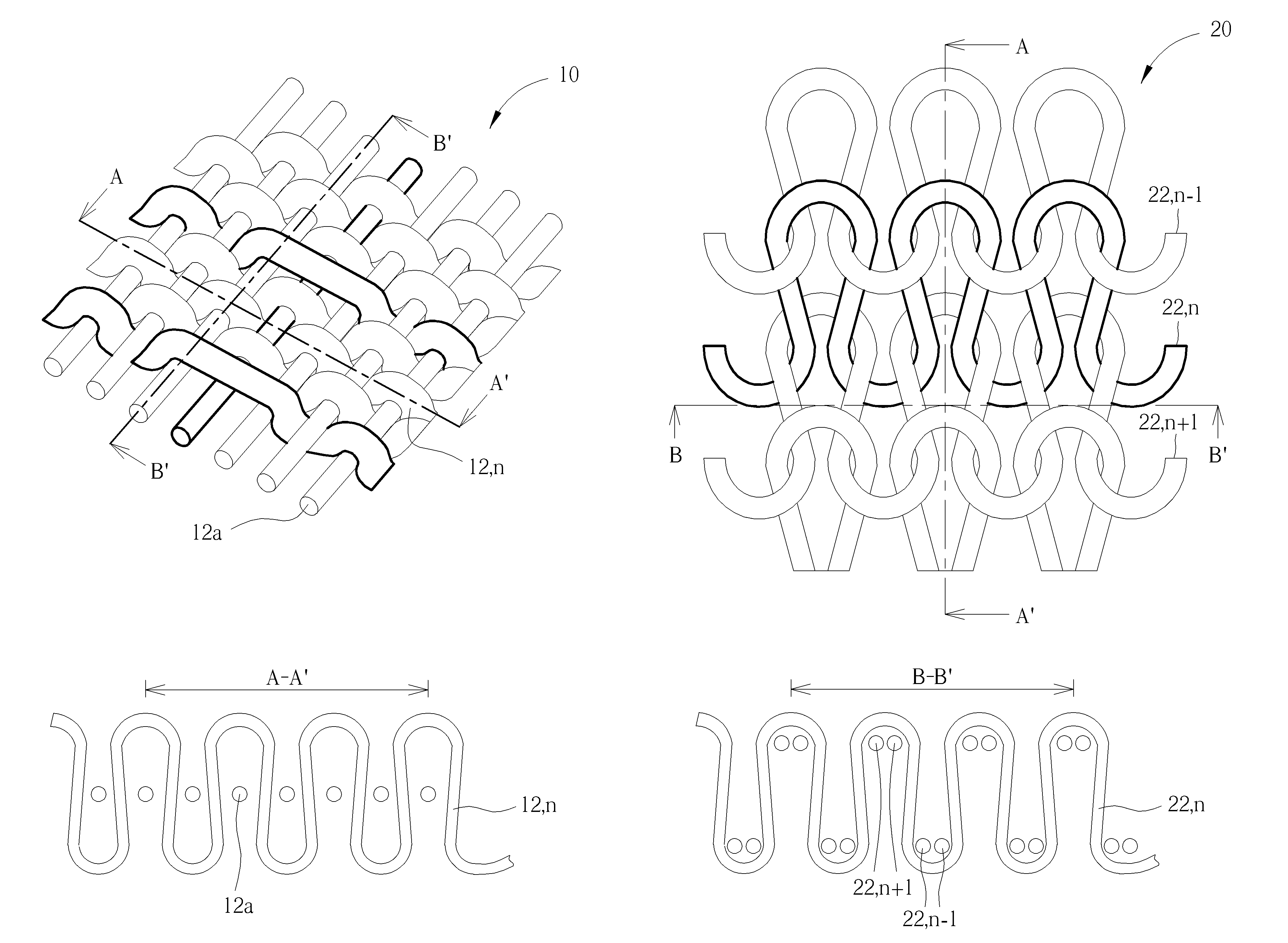
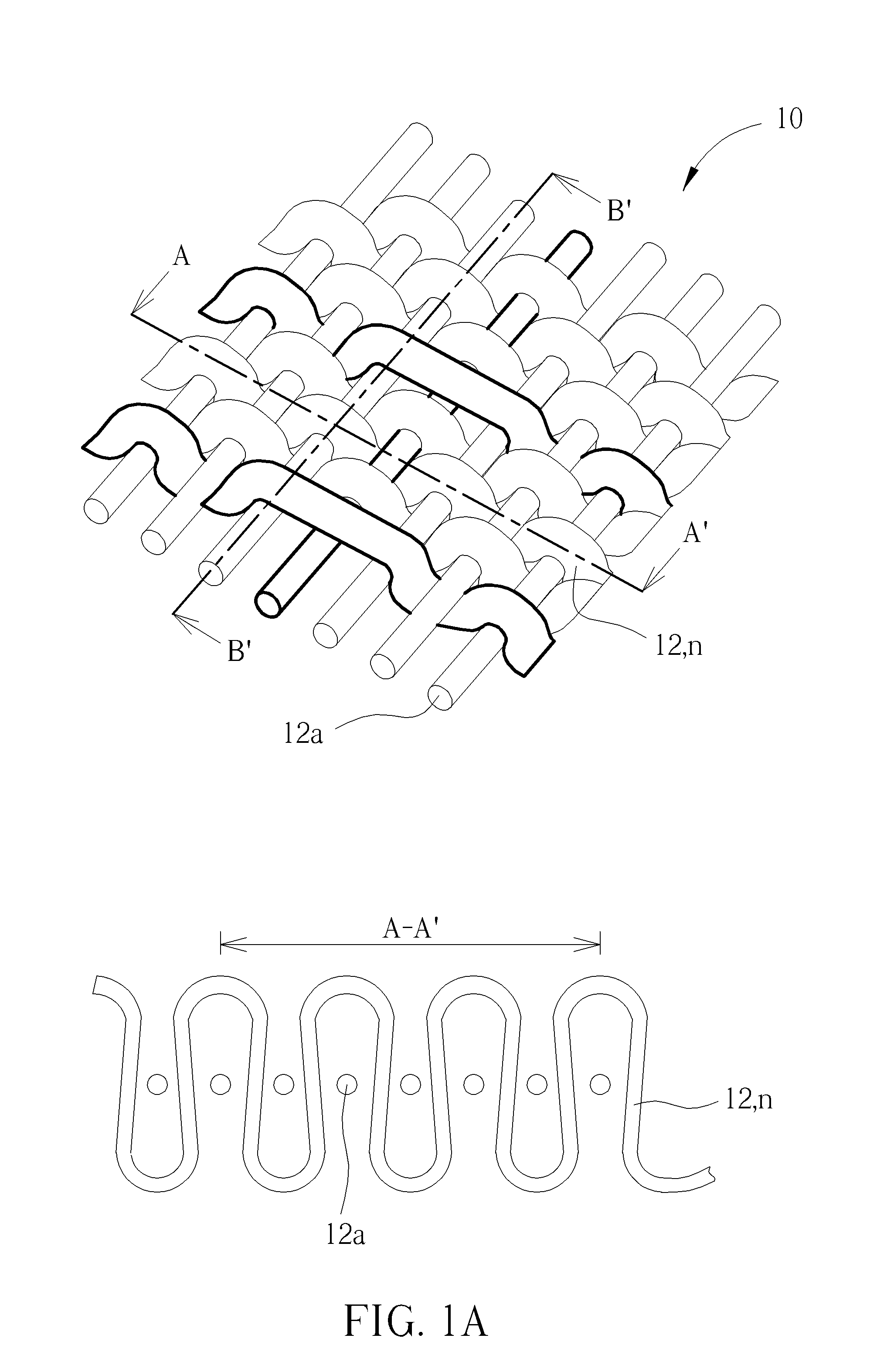
[0034] For better understanding the objective of the present invention, please refer to FIG. 1A, FIG. 1B and FIG. 1C, which are schematic diagrams exemplarily showing the common assembling structures of fabrics made by weaving or knitting.
[0035] Please refer to FIG. 1A. FIG. 1A shows an assembling structure of a woven fabric 10, in which the top portion is a perspective view of the fabric 10, and the lower portion is a cross-sectional view taken along the warp direction A-A' of the fabric 10. The fabric 10 as shown in FIG. 1A is formed by assembling (interlacing or interweaving) at least two sets of yarns 12 and 12a. Yarns 12 parallel with the warp direction A-A' (the prolonging direction of the fabric) are warps. Yarns 12a parallel with the weft direction (the widthwise direction of the fabric 10) and assembled with yarns 12 at right angles are wefts. Yarns 12 and 12a may respectively be monofilament or multifilament yarns.
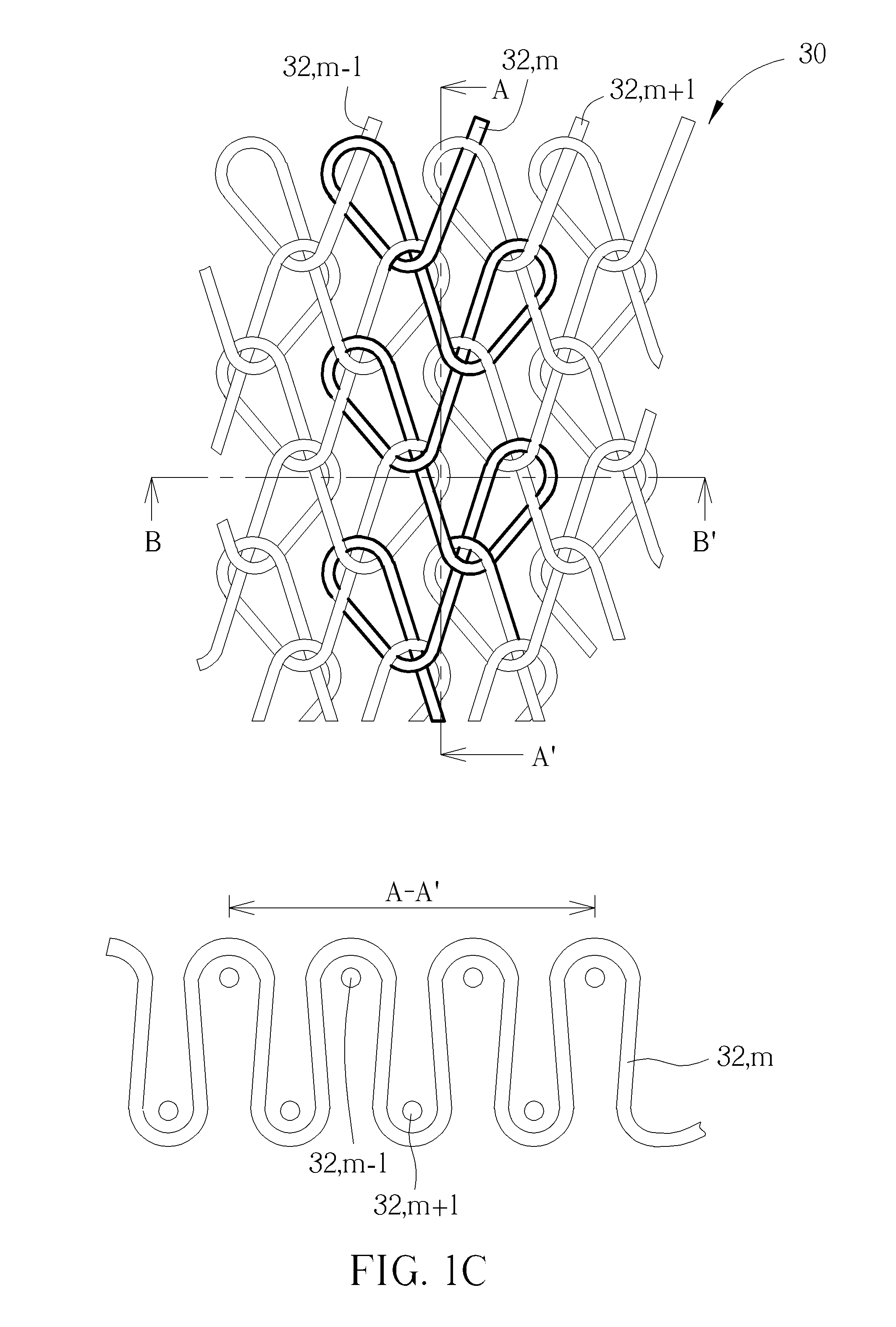
[0036] Please refer to FIG. 1B and FIG. 1C. FIG. 1B shows an assembling structure of a weft-knitted fabric 20 formed by assembling at least a yarn 22. The upper portion of FIG. 1B is a plan-view, and the lower portion of FIG. 1B is a cross-sectional view taken along the weft direction B-B' of the fabric 20. FIG. 1C shows an assembling structure of a warp-knitted fabric 30 formed by assembling a set of yarns 32. The upper portion of FIG. 1C is a plan-view, and the lower portion of FIG. 1C is a cross-sectional view taken along the warp direction A-A' of the fabric 30. Generally, in a knitted fabric, a row of loops arranged along the weft direction (the widthwise direction of the fabric) is referred as a course, and a column of loops arranged along the warp direction (the lengthwise direction of the fabric) is referred as a wale. During the process of forming a weft-knitted fabric 20 as shown in FIG. 1B, the yarn 22 is supplied to a knitting machine from the weft direction B-B' and successively placed on a row of needles for being manipulated into a row of lateral-connected loops, herein designated as course number n. Subsequently, the yarn 22 re-enters the knitting machine from the opposite side of the weft direction B-B' and successively placed on the needles for being manipulated into another row of lateral-connected loops, herein designated as course number n+1. At the same time of forming course number n+1 of yarn 22, by a series of lapping and shogging movements of the needles, each loop of course number n+1 is assembled (interlaced or interlooped) with the corresponding loop of course number n formed previously by the same needle, thereby prolonging the weft-knitted fabric 20 with assembled courses. On the other hand, during the process of forming a warp-knitted fabric 30 as shown in FIG. 1C, a set or several sets of parallel yarns 32 are supplied to a knitting machine respectively from the warp direction and placed on the needles for being manipulated into columns of vertical-connected loops, herein designated as wales number m-1, m and m+1. Meanwhile, by alternately placing the yarns 32 on adjacent needles for being interlooped with loops of another yarn previously formed on the needles, wales number m-1, m and m+1 formed from different yarns 32 are laterally interconnected as the knitting process continues to prolong the warp-knitted fabric 30.
[0037] Nowadays, various stitches have been developed for weaving, weft-knitting or warp-knitting. For example, a woven fabric may include plain stitch, twill stitch, satin stitch or combination thereof. A woven fabric may have warps or wefts braided, twisted, crossed or ribbed for better strength, texturing or appearance, but not limited hereto. A knitted fabric may include weft plain stitch, rib stitch, purl stitch, chain stitch, tricot stitch, satin tricot stitch, double loop stitch, tuck stitch, derivative stitch or the like, or combination thereof, but not limited hereto. It should be understood that the fabrics provided by the present invention may be formed by weaving, weft-knitting or warp-knitting process and may include various stitches. In the following description, several embodiments are provided with reference to associated schematic diagrams in which only components considered necessarily for understanding the concept of the present invention are shown while other components may be omitted for the sale of simplicity.
[0038] FIG. 2 and FIG. 3 are schematic illustrative diagrams of a fabric 100 according to a first embodiment of the present invention. Please refer to FIG. 2. The upper portion of FIG. 2 is a perspective view of the fabric 100, and the lower portion of FIG. 2 is a cross-sectional view of the fabric 100. The fabric 100 includes a base layer 110 formed by assembling at least yarn 112 through a continuous process (weaving or knitting) and having a first surface 110a and a second surface 110b opposite to the first surface 110a of the base layer 110. In the following description, the term "surface" or "upper surface" of a fabric or a textile layer is the surface presenting the stitch of the fabric and used in defining the thickness of the fabric, or may be the outermost surface exposed for perceptible texture. In the present invention, the surfaces of a fabric or a textile layer are drawn as a plane for the sake of simplicity. Usually, the surface of a fabric may provide a coarse texture when the textures of yarns forming the fabric are felt. The fabric 100 further includes a first covering layer 120 formed on the first surface 110a and at least partially covering the first surface 110a. The first covering layer 120 is simultaneously formed with the base layer 110 by assembling at least a second yarn 122 during the continuous process of forming the base layer 110. In other words, the fabric 100 provided by the present invention substantially has a unitary one-piece construction formed by manipulating the first yarn 112 and the second yarn 122 respectively into the base layer 110 and the first covering layer 120 in the same continuous weaving or knitting process. According to an embodiment when the fabric 100 is formed by a weaving, the winding first yarn 112 and second yarn 122 shown in the lower portion of FIG. 2 may be considered as the warp yarn of the base layer 110 and the first covering layer 120, such as the warp yarn 12 shown in FIG. 1A. In another embodiment when the fabric 100 is formed by weft-knitting, the winding first yarn 112 and second yarn 122 shown in the lower portion of FIG. 2 may be considered as a course of loops made from yarn 112 or 122 along the weft direction of the fabric 100, such as the course made from yarn 22 shown in FIG. 1B. In still another embodiment when the fabric 100 is formed by warp-knitting, the winding first yarn 112 and second yarn 122 shown in the lower portion of FIG. 2 may be considered as a wale of loops made from yarn 112 or 122 along the warp direction of the fabric 100, such as the wale made from yarn 32 shown in FIG. 1C. To further simplify the diagrams, other rows or columns assembled with the drawn yarns 112 and 122 are not shown in FIG. 2 and other diagrams in the present invention. Because the first covering layer 120 is formed by weaving or knitting, the first surface 110a of the base layer 110 may be seen through fabric pores created by the assembling second yarn 122 especially when the first covering layer 120 exhibits a small stitch density (or high fabric porosity).
[0039] According to one embodiment, the first yarn 112 for forming the base layer 110 may be monofilament or multifilament. The first yarn 112 may be made of materials selected from the group previously illustrated. Preferably, the first yarn 112 comprises thermoplastic polymer, such as polyethylene terephthalate (PET).
[0040] According to the embodiment, the second yarn 122 for forming the first covering layer 120 may be monofilament or multifilament. The first yarn 112 may be made of materials selected from the group previously illustrated. Preferably, the second yarn 122 is monofilament comprising thermoplastic polymer, such as thermoplastic urethane (TPU) which is known for thermofusion stability, thermoplasticity with adjustable melting point for process convenience. According to an embodiment, the second yarn 122 may have a thread size of linear mass density between 150 and 1800 dens (denier). It is noteworthy that when both the first yarn 112 and the second yarn 122 are made of thermoplastic polymer, the melting point of the second yarn 122 should be lower than the melting point of the first yarn 112 to prevent the first yarn 112 from being melted and causing unexpected deformation of the base layer 110 when performing a subsequent heat-setting step to transform the first covering layer 120 into a first film 130 (shown in FIG. 3). Preferably, the melting point of the second yarn 122 is at least 20 degrees Celsius lower than the melting point of the first yarn 112. More preferably, the melting point of the second yarn 122 is at least 30 degrees Celsius lower than the melting point of the first yarn 112. For example, in a practice of the invention, the first yarn 112 forming the base layer 110 is made of PET and has a melting point approximately 250 degrees Celsius, and the second yarn 122 forming the first covering layer 120 is made of TPU and has a melting point equal to or smaller than 220 degrees Celsius. The stitches of the base layer 110 and the first covering layer 120 may be integrally designed by computer aided manufacturing (CAM) technique. The design is then input to a computer-controlled knitting or weaving machine by which the continuous weaving or knitting process is performed wherein the first yarn 112 and the second yarn 122 are simultaneously manipulated into the base layer 110 and the first covering layer 120, respectively. It is noteworthy that when needles are used to manipulate the yarns, the thread size of the yarns should be adjusted according to needle sizes. According to a practice of the present invention, the thread size of the yarns 112 and yarn 122 used for forming the fabric 100 preferably have a linear mass density smaller than 900 dens, for example, approximately 600 dens.
[0041] Please refer to FIG. 3. After the fabric 100 including the base layer 110 and the first covering layer 120 are produced, they may be subjected to a heat-setting step to make the second yarn 122 of the first covering layer 120 at least partially melted and fused into a first film 130 covering the same region of the first surface 110a originally covered by the first covering layer 120. The heat-setting step may be carried out using heat press by a roller or mold, or heat-flue setting by an oven, but not limited. The temperature of the heat-setting step is equal to or higher than the melting point of the second yarn 122, and preferably, by at least 5 degrees Celsius. For example, when the second yarn 122 has a melting point approximately at 180 degrees Celsius, the heat-setting step may be carried out at approximately 200 degrees Celsius, and preferably 185 degrees Celsius. According to an embodiment, after the heat-setting step, as shown in the upper portion of FIG. 3, the second yarn 122 of the first covering layer 120 may be melted to completely lose its original texture (deformed to lose its original thread profile) and fused into a first film 130, which may have an upper surface with a smooth texture and does not show any texture of the second yarn 122. According to another embodiment, as shown in the lower portion of FIG. 3, the second yarn 122 of the first covering layer 120 is only partially melted, partially keeping its original texture and partially fused form to form the first film 130 during the heat-setting step. Therefore, the first film 130 may present a partial texture of the second yarn 122 and may have an upper surface having a coarse texture. Preferably, the first film 130 is a continuous film uniformly covering the region of the first surface 110a originally covered by the first covering layer 120 without any pores exposing the first surface 110a. Advantageously, by selecting TPU as the material to form the second yarn 122 of the first covering layer 120 therefore obtaining the first film 130 made of TPU, the region of the first surface 110a covered by the first film 130 may have improved moisture resistance properties to prevent moisture from permeating into the base layer 110 from the first surface 110a. Meanwhile, the region of the first surface 110a covered by the first film 130 made of TPU may also have improved wear-resistance properties. Furthermore, the first film 130 made of TPU may have better fusion and laminating to the first surface 110a of the base layer 110 after the heat-setting step.
[0042] One feature of the present invention is that, the fabric 100 with functional component(s) incorporated therein is made of a unitary one-piece construction by simultaneously assembling the first yarn 112 and the functional second yarn 122 respectively into base layer 110 and the first covering layer 120 covering a pre-determined region of first the surface of the base layer 120, allowing the functional first film 130 being formed with precisely controlled shape and placement. The fabric 100 provided by the present invention may be formed in a simplified process in high degree of automation without the need of performing conventional cutting, aligning, adhering, and heating process for adding functional component(s) to the base fabric.
[0043] Please refer to drawing (a) of FIG. 23, illustrating a top view of a fabric 100 according to the first embodiment of the present invention used for forming a footwear upper. As illustrated in the first embodiment, the fabric 100 includes a base layer 110 formed by assembling at least a first yarn 112. The base layer 110 may include a pre-determined first region 114a defined therein. For example, the fabric 100 may be cut into a full upper of a footwear article along the outer perimeter of the first region 114a. The fabric 100 further includes a first covering layer 120 formed on the first surface (the drawing plane) 110a and covering the first region 114a. The first surface 110a of the fabric 100 may be an exterior surface of the footwear upper, which is opposite to the interior surface facing the foot. On the contrary, the first surface 110a of the fabric 100 may be an interior surface facing the foot. It is important that the fabric 100 is made of a unitary one-piece construction by simultaneously manipulating the first yarn 112 and the second yarn 122 respectively into the base layer 110 and the first covering layer 120 through a continuously process (may be weaving or knitting) of forming the fabric 100. The fabric 100 may be subjected to a heat-setting step to make the first covering layer 120 at least melted and fused into a first film 130 on the first surface 110a and covering the first region 114a. The region covered by the first film 130 may have improved moisture resistance, wear-resistance and fusion property. According to an embodiment where the first yarn 112 of the base layer 110 comprises thermoplastic material, the heat-setting step may be carried out at a temperature higher than the heat deflection temperature (HDT) of the first yarn 112 of the base layer 110 to simultaneously thermo-shape the base layer 110 and melting and fusing the first covering layer 120 into the first film 130 at the same time, thereby further simplifying the process steps.
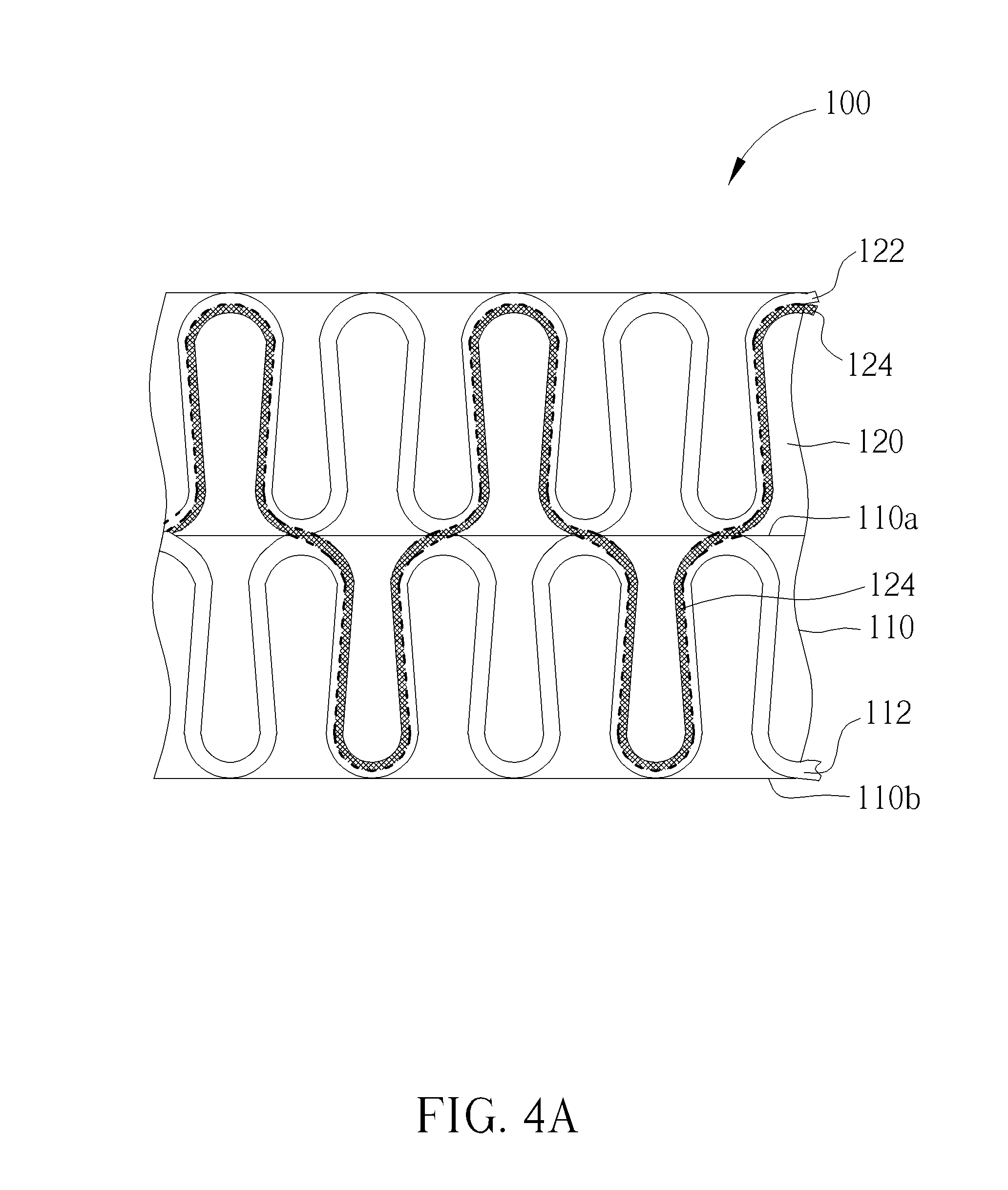
[0044] FIG. 4A, FIG. 4B and FIG. 5 are schematic illustrative diagrams of a fabric 100 according to a second embodiment of the present invention. Please refer to FIG. 4A. Similar to the first embodiment, the fabric 100 includes a base layer 110 and a first covering layer 120 formed on and at least partially covering a first surface 110a of the base layer 100. The difference with the first embodiment is that, in the second embodiment, the fabric 100 further includes at least an assistant second yarn 124 traversing back and forth between the base layer 110 and the first covering layer 120 to attach the first covering layer 120 intimately to the first surface 110a of the base layer 110 and also at least partially fill the fabric pores of the base layer 110 (created by the assembling first yarn 112) and the first covering layer 120 (created by the assembling first yarn 112). The assistant second yarn 124 may comprise the same material as the second yarn 122, such as the same thermoplastic polymer, and have substantially the same or close melting point. The structure of the fabric 100 is shown in schematic diagram FIG. 4A, illustrating the assistant second yarn 124 alternatively assembled with the first yarn 112 and the second yarn 122 thereby being bound into the base layer 110 and the first covering layer 120 during the continuous process of producing the fabric 100. More specifically, in an embodiment when the fabric 100 is formed by weaving, as shown in drawing (a) of FIG. 4B, the assistant second yarn 124 may alternatively extend with the first yarn 112 and the second yarn 122 along, for example, the warp direction of the fabric 100 and alternately intersecting with the weft yarns 112(a) and 122(a) thereby being assembled into the base layer 110 and the first covering layer 120 as the weaving process continues. In another embodiment when the fabric 100 is formed by weft-knitting, as shown in drawing (b) of FIG. 4B, the assistant second yarn 124 may be alternately placed on two sets of needles respectively holding the first yarn 112 and the second yarn 122, and then being looped and assembled with the loops of the first yarn 112 and the second yarn 122 by a series of lapping and shogging movement of the needles as the knitting process continues. Since the fabric 100 including the assistant second yarn 124 is formed through a continuous weaving or knitting process, the fabric 100 including the assistant second yarn 124 is still made of a unitary one-piece construction. Similarly, the fabric 100 including the assistant second yarn 124 may be formed in various stitches. In some embodiments, the assistant second yarn 124 may be exposed from the upper surface 120a of the first covering layer 120 and/or form the second surface 110b of the base layer 110. In other embodiments, the assistant second yarn 124 may not be exposed but may be observed through the fabric pores of the first covering layer 120 and/or the base layer 110.
[0045] Please refer to FIG. 5. Similarly, the fabric 100 as shown in FIG. 4 may be subjected to a heat-setting step to make the second yarn 122 of the first covering layer 120 at least partially melted and fused into a first film 130 covering the same region of the first surface 110a originally covered by the first covering layer 120. It is noteworthy that the assistant second yarn 124 may comprise the same material as the second yarn 122 or have a melting point equal or close to that of the second yarn 122. Consequently, the portion of the assistant second yarn 124 traversing in the first covering layer 120 may also be at least partially melted during the heat-setting step, fused with the melted second yarn 122 and constitute a part of the first film 130. Please refer to the upper portion of FIG. 5. According to one embodiment, the second yarn 122 and the portion of the assistant second yarn 124 traversing in the first covering layer 120 are melted to completely lose their original textures and fused with each other to collectively constitute the first film 130, which may have an upper surface with a smooth texture and does not show any textures of the second yarn 122 and the assistant second yarn 124. Please refer to the lower portion of FIG. 5. According to another embodiment, the second yarn 122 and the portion of the assistant yarn 124 traversing in the first covering layer 120 are only partially melted, keeping part of their original textures and partially fused with each other to form the first film 130 which may show partial profiles of the second yarn 122 and the assistant second yarn 124 and may have an upper surface with a coarse texture. On the other hand, the portion of the assistant second yarn 124 traversing in the base layer 110 may be partially melted to adhere to the first yarn 112 of the base layer 110 during the heat-setting step while keeping part of its original texture. By the assistant second yarn 124 at least partially fused into the first film 130 and meanwhile adhering to the first yarn 112 of the base layer 110, the first film 130 may be more securely attached on the first surface 110a of the base layer 110. Furthermore, when the assistant second yarn 124 is made of material having good thermo stability and tensile strength properties, such as thermoplastic elastomer (TPE), the assistant second yarn 124 may impart additional tensile strength to the base layer 110 by assembling with and adhering to the first yarn 112 of the base layer 110. In some embodiments, the assistant second yarn 124 traversing in the base layer 110 may be completely melted (not shown) during the heat-setting step to fill the fabric pores of the base layer 110.
[0046] FIG. 6 and FIG. 7 are schematic illustrative diagrams of a fabric 100 according to a third embodiment of the present invention. Please refer to FIG. 6. Similar to the first embodiment, the fabric 100 includes a base layer 110 and a first covering layer 120 formed on and at least partially covering a first surface 110a of the base layer 110. The difference with the first embodiment is that, in the third embodiment, the fabric 100 further includes two or more assistant second yarns 124 and 126 traversing back and forth between the base layer 110 and the second covering layer 120 to attach the first covering layer 120 intimately to the first surface 110a of the base layer 110 and also at least partially fill the fabric pores of the base layer 110 and the first covering layer 120. The assistant second yarns 124 and 126 may comprise the same material as the second yarn 122, such as the same thermoplastic polymer, and have substantially the same or close melting point. The structure of the fabric 100 including the assistant second yarns 124 and 126 is shown in schematic diagram FIG. 6, illustrating the assistant second yarns 124 and 126 respectively and alternatively assembled with the first yarn 112 and the second yarn 122 thereby being bound into the base layer 110 and the first covering layer 120 during the continuous process of producing the fabric 100. The fabric 100 of the third embodiment may be formed by weaving or knitting. The method of integrally manipulating the first yarn 112, second yarn 122 and the assistant second yarns 124 and 126 when forming the fabric 100 may be understood by reference to the second embodiment previously illustrated. Similarly, the fabric 100 including the assistant second yarns 124 and 126 may be formed with various stitches. In some embodiments, the assistant second yarns 124 and 126 may be exposed from the upper surface 120a of the first covering layer 120 and/or form the second surface 110b of the base layer 110. In other embodiments, the assistant second yarns 124 and 126 may not be exposed but may be observed through the fabric pores of the first covering layer 120 and/or the base layer 110.
[0047] Please refer to FIG. 7. The fabric 100 as shown in FIG.6 may be subjected to a heat-setting step to make the second yarn 122 of the first covering layer 120 at least partially melted and fused into a first film 130 covering the same region of the first surface 110a originally covered by the first covering layer 120. When the assistant second yarns 124 and 126 comprise the same material as the second yarn 122 or have a melting point equal or close to that of the second yarn 122, the assistant second yarns 124 and 126 traversing in the first covering layer 120 may also be at least partially melted during the heat-setting step and fused with the melted second yarn 122 and constitute a part of the first film 130. Please refer to the upper portion of FIG. 7. According to one embodiment, the second yarn 122 and the respective portions of the assistant second yarns 124 and 126 traversing in the first covering layer 120 are melted to completely lose their original textures and fused with each other to collectively form the first film 130, which may have an upper surface with a smooth texture and does not show any textures of the second yarn 122 and the assistant second yarns 124 and 126. Please refer to the lower portion of FIG. 7. According to another embodiment, the second yarn 122 and the respective portions of the assistant second yarns 124 and 126 traversing in the first covering layer 122 are only partially melted to partially keep their original textures and partially fused with each other to form the first film 130, which may show partial textures of the second yarn 122 and the assistant second yarns 124 and 126 and may have an upper surface with a coarse texture. On the other hand, the respective portions of the assistant second yarns 124 and 126 traversing in the base layer 110 may be partially melted and adhere to the first yarn 112 of the base layer 110 after the heat-setting step while keeping part of their respective textures. By utilizing two or more assistant second yarns 124 and 126 fused into the first film 130 and meanwhile adhering to the first yarn 112 of the base layer 110, the first film 130 may be more securely attached on the first surface 110a of the base layer 110. In some applications, the assistant second yarns 124 and 126 traversing in the base layer 110 may be completely melted during the heat-setting step to fill the fabric pores of the base layer 110.
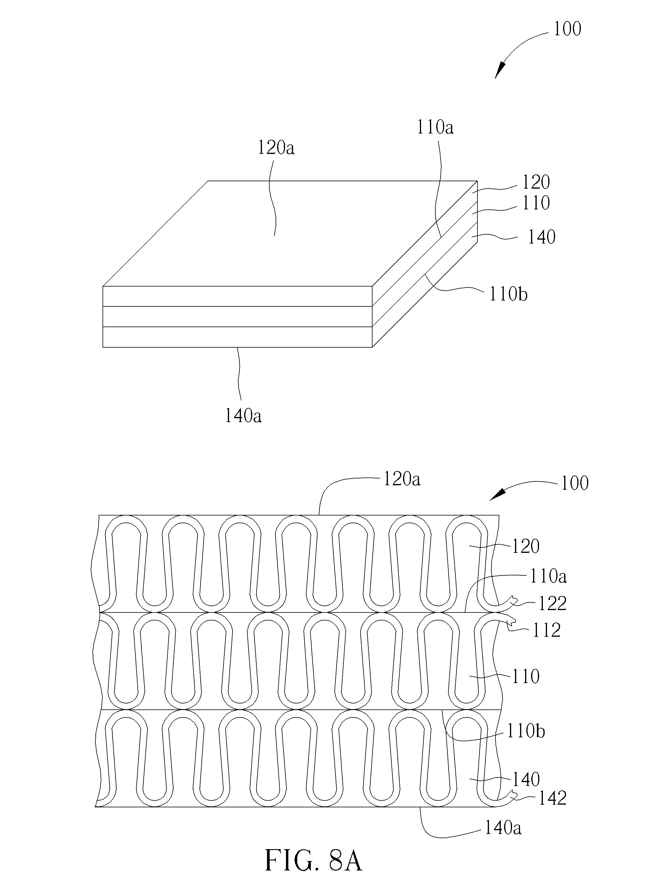
[0048] FIG. 8A, FIG. 8B and FIG. 9 are schematic illustrative diagrams of a fabric according to a fourth embodiment of the present invention. Please refer to FIG. 8A. Similar to the first embodiment, the fabric 100 includes a base layer 110 and a first covering layer 120 formed on and at least partially covering a first surface 110a of the base layer 100. The difference with the first embodiment is that, in the fourth embodiment, the fabric 100 further includes a second covering layer 140 formed on and at least partially covering the second surface 110b of the base layer 110. The second covering layer 140 is simultaneously formed with the base layer 110 by assembling at least a third yarn 142 during the continuous process of forming the base layer 110. In other words, the fabric 100 according to the fourth embodiment substantially has a unitary one-piece construction formed by manipulating the first yarn 112, the second yarn 122 and the third yarn 142 respectively into the base layer 110, the first covering layer 120 and the second covering layer 140 in the same continuous weaving or knitting process. The first covering layer 120 and the second covering layer 140 on the opposite surfaces of the base layer 110 may be formed at least partially overlapped (as shown in FIG. 8A) or completely not overlapped with each other (as shown in FIG. 8B). The second surface 110b of the base layer 110 may be observed through the fabric pores of the second covering layer 140 (created by the assembling the third yarns 142) when the second covering layer 140 has a small stitch density (or a high fabric porosity). According to an embodiment, the third yarn 142 may be monofilament or a multifilament. The first yarn 112 may be made of materials selected from the group previously illustrated, but not limited hereto. Preferably, the both the second yarn 122 and the third yarn 142 are monofilament yarns and comprising thermoplastic polymer, such as thermoplastic urethane (TPU), and therefore have the same or close melting points preferably between 110 and 250 degrees Celsius, more preferably between 180 and 200 degrees Celsius. According to a practice of the present invention, the third yarn 142 preferably has a thread size of linear mass density between 150 and 1800 dens. In other embodiments, the second yarn 122 and the third yarn 142 may be made of the same material but have different melting points, or may be made of different materials.
[0049] Please refer to FIG. 9. The fabric 100 as shown in FIG. 8 may be subjected to a heat-setting step to make the second yarn 122 of the first covering layer 120 and the third yarn 142 of the second covering layer 140 at least partially melted and respectively fused into the first covering layer 130 and the second covering layer 150 covering the opposite surfaces of the base layer 110. According to one embodiment, as shown in the upper portion of FIG. 9, the second yarn 122 and the third yarn 142 may be melted to completely lose their respective textures, and thereby the obtained first film 130 and the second film 150 may respectively have an upper surface with smooth texture and does not show any texture. According to another embodiment, as shown in the lower portion of FIG. 9, the second yarn 122 and the third yarn 142 may be only partially melted, keeping part of their original texture and partially fused to respectively form the first film 130 and the second film 150 showing partial textures of the yarns and may have coarse texture. Preferably, the second film 150 is a continuous film uniformly covering the region of the second surface 110b originally covered by the second covering layer 140 without any pores exposing the second surface 110b. Advantageously, by selecting TPU as the material to form the third yarn 142 of the second covering layer 140 therefore obtaining the second film 150 made of TPU, the region of the second surface 110b covered by the second film 150 may have improved moisture resistance properties to prevent moisture from permeating into the base layer 110 from the second surface 110b. Meanwhile, the region of the second surface 110b covered by the second film 150 made of TPU may also have improved wear-resistance properties. Furthermore, the second film 150 made of TPU may have better fusion and laminating to the second surface 110b of the base layer 110 after the heat-setting step
[0050] Please refer to drawing (b) of FIG. 23, illustrating top view of a fabric 100 according to the fourth embodiment of the present invention used for forming a footwear upper. As previously illustrated, the fabric 100 according to the fourth embodiment includes a base layer 110 formed by assembling at least a first yarn 112. The fabric 100 further includes a first covering layer 120 on the first surface (drawing plane) 110a and covering a pre-determined first region 114a of the base layer 110. For example, along the outer perimeter of the first region 114a, the fabric 100 may be cut into a full upper of a footwear article. The fabric 100 further includes a second covering layer 140 on the second surface (opposite of the drawing plane) 110b and covering a pre-determined second region 114b of the base layer 110. It is important that the fabric 100 is made of a unitary, one-piece construction by simultaneously manipulating the first yarn 112, the second yarn 122 and the third yarn 142 respectively into the base layer 110, the first covering layer 120 and the third covering layer 140 through a continuously process (may be weaving or knitting) of forming the fabric 100. According to an embodiment, the first surface 110a of the fabric 100 may be an exterior surface of the upper which faces away from the foot, and the second surface 114b is an interior surface facing the foot, or vice versa. According to an embodiment, the first region 114a excluding the second region 114b may be associated with the fore portion and lower medial and rear portions of a footwear upper, which may be positioned close to the sole (not shown) of a footwear article. The second region 114b maybe associated with the rest portion of the footwear upper. In other embodiments (not shown), the first region 114a and the second region 114b may be completely overlapped. As previously illustrated, the fabric 100 may be subjected to a heat-setting step to make the first covering layer 120 and the second covering layer 140 at least partially melted and respectively fused into a first film (not shown) on the first surface 110a covering the first region 114a and a second film (not shown) on the second surface 110b covering the second region 114b. The moisture resistance properties, wear-resistance properties and fusion properties of the first surface 110a and the second surface 110b of the base layer 11 may be improved.
[0051] FIG. 10 and FIG. 11 are schematic illustrative diagrams of a fabric according to a fifth embodiment of the present invention. Please refer to FIG. 10. Similar to the fourth embodiment, the fabric 100 includes a base layer 110, a first covering layer 120 covering a first surface 110a of the base layer 110 and a second covering layer 140 covering a second surface 110b of the base layer 110. The difference from the fourth embodiment is that, in the fifth embodiment, the fabric 100 further includes at least an assistant second yarn 124 traversing back and forth between the base layer 110 and the first covering layer 120, and at least an assistant third yarn 144 traversing back and forth between the base layer 110 and the second covering layer 140 to attach the first covering layer 120 and the second covering layer 140 respectively intimately to the first surface 110a and the second surface 110b, and meanwhile fill the fabric pores of the base layer 110, the first covering layer 120 and the second covering layer 140. According to an embodiment, the assistant second yarn 124 may comprise the same material as the second yarn 122, and the assistant third yarn 144 may comprise the same material as the third yarn 142. The structure of the fabric 100 including the assistant second yarns 124 and assistant third yarn 144 as shown in schematic diagram FIG. 10, illustrating the assistant second yarn 124 alternatively assembled with the first yarn 112 and the second yarn 122 thereby being bound into the base layer 110 and the first covering layer 120, and the assistant third yarn 144 alternatively assembled with the first yarn 112 and the third yarn 142 thereby being bound into the base layer 110 and the second covering layer 140 during the continuous process of producing the fabric 100, and the fabric 100 is considered as a unitary one-piece fabric. Similarly, the fabric 100 including the assistant second yarn 124 and the assistant third yarn 144 may be formed with various stitches. The assistant second yarn 124 and the assistant third yarn 144 may be exposed from the outermost surface of the fabric or not exposed. For example, the assistant second yarn 124 may be exposed from the upper surface 120a of the first covering layer 120 and/or form the second surface 110b of the base layer 110 that is not covered by the second covering layer 140. On the contrary, the assistant second yarn 124 may be unexposed but able to be observed from the upper surface 120a of the first covering layer 120 through the fabric pores of the first covering layer 120 and/or from the second surface 110b of the base layer 110 not covered by the second covering layer 140 through the fabric pores of the base layer 110. Similarly, the assistant third yarn 144 may be exposed from the upper surface 140a of the second covering layer 140 and/or form the first surface 110a of the base layer 110 not covered by the first covering layer 120. On the contrary, the assistant third yarn 144 may be unexposed but able to be observed from the upper surface 140a of the second covering layer 140 through the fabric pores of the second covering layer 140 and/or from the first surface 110a of the base layer 110 not covered by the first covering layer 120 through the fabric pores of the base layer 110.
[0052] Please refer to FIG. 11. The fabric 100 as shown in FIG. 10 may be subjected to a heat-setting step to make the second yarn 122 of the first covering layer 120 and the third yarn 142 of the second covering layer 140 at least partially melted and respectively fused into a first film 130 and a second film 150 covering the opposite surfaces of the base layer 110. It is noteworthy that the assistant second yarn 124 and the assistant third yarn 144 may respectively comprise the same material as the second yarn 122 and the third yarn 142, or may have melting points equal or close to that of the second yarn 122 and third yarn 142. Consequently, the portion of the assistant second yarn 124 traversing in the first covering layer 120 and the portion of the assistant third yarn 144 traversing in the second covering layer 140 may also be at least partially melted during the heat-setting step and respectively fused with the melted second yarn 122 and third yarn 142 to constitute a part of the first film 130 and the second film 150. According to one embodiment, as shown in the upper portion of FIG. 11, the second yarn 122, the portion of the assistant second yarns 124 traversing in the first covering layer 120, the third yarn 142 and the portion of the assistant third yarn 144 traversing in the second covering layer 140 are melted to completely lose their original textures and fused to form the first film 130 and the second film 150 having upper surfaces with a smooth texture without showing any textures of the yarns. In another embodiment, as shown in the lower portion of FIG. 11, the second yarn 122, the portion of the assistant second yarns 124 traversing in the first covering layer 122, the third yarn 142 and the portion of the assistant third yarn 144 traversing in the second covering layer 140 are only partially melted, keeping part of their own textures and partially fused to form the first film 130 and the second film 150 showing partial textures of the yarns and may have coarse textures. On the other hand, the portions of the assistant second yarns 124 and the assistant third yarns 144 traversing in the base layer 110 may be partially melted to adhere to the first yarn 112 of the base layer 110 during the heat-setting step while preserving part of their textures. By the assistant second yarn 124 and the assistant third yarn 144 at least partially fused into the first film 130 and the second film 150 and meanwhile adhering to the first yarn 112 of the base layer 110, the first film 130 and the second film 150 may be more securely attached on the first surface 110a and second surface 110b of the base layer 110. In some embodiments, the assistant second yarns 124 and the assistant third yarn 144 traversing in the base layer 110 maybe completely melted (not shown) during the heat-setting step to fill the fabric pores of the base layer 110.
[0053] Please still refer to FIG. 11. When the portions of the assistant second yarn 124 and the assistant third yarn 144 traversing in the base layer 110 are respectively exposed form the second surface 110b and first surface 110a of the base layer 110, or when the first film 130 and the second film 150 partially fill into the fabric pores of the base layer 110, the portions of the assistant second yarn 124 and the assistant third yarn 144 traversing in the base layer 110 may be able to adhere to the second film 150 and first film 130 in the overlapping region of the first film 130 and the second film 150, and therefore the first film 130 and second film 150 are more securely attached to the base layer 110 and the relative displacement is prevented. When the fabric 100 includes two or more assistant second yarns traversing back and forth between the base layer 110 and the first covering layer 120 (similar to FIG. 6) and/or two or more third assistant yarns traversing back and forth between the base layer 110 and the second covering layer 140, the first film 130 and the second film 150 may be more securely attached to the base layer 110, and more fabric pores of the base layer 110, the first covering layer 120 and the second covering layer 140 may be better filled.
[0054] FIG. 12 and FIG. 13 are schematic illustrative diagrams of a fabric 100 according to a sixth embodiment of the present invention. Please refer to FIG. 12. Similar to the fourth embodiment previously shown in FIG. 8A, the fabric 100 includes a base layer 110, a first covering layer 120 and a second covering layer 140 covering the opposite surfaces of the base layer 110. The difference from the fourth embodiment is that, the fabric 100 according to the sixth embodiment as shown in FIG. 12 further includes at least an assistant second yarn 124 traversing back and forth between the first covering layer 120, the base layer 110 and the second covering layer 130 thereby attaching the first covering layer 120 and the second covering layer 130 respectively intimately to the first surface 110a and second surface 110b of the base layer 110, and also at least partially filling the fabric pores of the base layer 110, first covering layer 120 and the second covering layer 140. The assistant second yarn 124 may comprise the same material as the second yarn 122. The structure of the fabric 100 is shown in schematic diagram FIG. 4A, illustrating that during the continuous process of forming the fabric 100, the assistant second yarn 124 repeatedly penetrates through the base layer 110 back and forth and alternately assembled with the second yarn 122 of the first covering layer 120 and the third yarn 142 of the second covering layer 140, thereby being bound into the first covering layer 120 and the second covering layer 140 between which the base layer 110 is sandwiched. Similarly, the assistant second yarn 124 maybe exposed from the upper surface 120a of the first covering layer 120 and/or form the upper surface 140a of the second covering layer 140. In other embodiments, the assistant second yarn 124 may be unexposed but may be observed through the fabric pores of the first covering layer 120 and the second covering layer 140. It should be understood that, in other embodiments, an assistant third yarn 144 (not shown) made of the same material as the third yarn 142 may substitute for the assistant second yarn 122 in FIG. 12 as the traversing yarn.
[0055] Please refer to FIG. 13. The fabric 100 shown in FIG. 12 may be subjected to a heat-setting step to make the second yarn 122 of the first covering layer 120 and the third yarn 142 of the second covering layer 140 at least partially melted and respectively fused into a first film 130 and a second film 150 on the first surface 110a and second surface 110b of the base layer 110. The assistant second yarn 124 is also at least partially melted during the heat-setting step and at least partially fused with the second yarn 122 and the third yarn 142 and constitute a part of the first film 130 and second film 150, respectively. According to an embodiment, as shown in the upper portion of FIG. 13, the second yarn 122, the third yarn 142 and the portions of the assistant second yarn 124 traversing in the first covering layer 120 and the second covering layer 140 are melted to completely lose their textures, the obtained first film 130 and the second film 150 may have upper surfaces having smooth texture without showing any texture of the yarns. According to another embodiment, as shown in the lower portion of FIG. 13, the second yarn 122, the third yarn 142 and the portions of the assistant second yarn 124 traversing in the first covering layer 120 and the second covering layer 140 are only partially melted, keeping part of their textures, the obtained first film 130 and second film 150 may show partial textures of the yarns and may have coarse texture. On the other hand, the portion of the assistant second yarn 124 traversing in the base layer 110 may be partially melted, keep partial texture and adhere to the first yarn 112 of the base layer 110. In some embodiments, the assistant second yarn 124 traversing in the base layer 110 may be completely melted (not shown) during the heat-setting step to fill the fabric pores of the base layer 110. The assistant second yarn 124 provides a secure interconnection between the base layer 110, the first film 130 and the second film 150, allowing the first film 130 and the second film 150 securely attached to the first surface 110a and second surface 110b of the base layer 110, respectively.
[0056] FIG. 14A, FIG. 14B, FIG. 15A, FIG. 15B and FIG. 16 are schematic illustrative diagrams of a fabric 100 according to a seventh embodiment of the present invention. The fabric 100 according to the seventh embodiment of the present invention includes a base layer 110 formed by assembling at least a first yarn 112 through a continuous process (weaving or knitting), and at least an embedded yarn 128 (first embedded yarn) simultaneously inlaid or assembled into at least partial region of the base layer 110 during the continuous process of forming the base layer 110. In other words, the fabric 100 according to the seventh embodiment substantially has a unitary one-piece construction by simultaneously manipulating the first yarn 112 and the embedded yarn 128 in the same continuous weaving or knitting process. When the fabric 100 is formed by weaving, the embedded yarn 128 may extend parallel with the weft yarn 112a and intersect with the warp yarn 112, as shown in drawing (a) of FIG. 14A and drawing (a) of FIG. 14B, or may extend parallel with the warp yarns 112 and intersecting with the weft yarn 112a, as shown in drawing (b) of FIG. 14A and drawing (b) of FIG. 14B. When the fabric 100 is produced by knitting, the embedded yarn 128 is usually supplied to the knitting machine from the direction the same as the first yarn 112. For example, when the fabric 100 is formed by weft-knitting, the embedded yarn 128 and the first yarn 112 enter the knitting machine from the weft direction. When the fabric 100 is formed by warp-knitting, the embedded yarn 128 and the first yarn 112 enter the knitting machine from the warp direction. When the fabric is formed by knitting, the embedded yarn 128 may be incorporated into the base layer 110 in the following two ways, for example. Please refer to drawing (a) of FIG. 15A and drawing (a) of FIG. 15B. The embedded yarn 128 may extend along the first yarn 112 and be manipulated into loops which are assembled (or interloped) with courses (or wales) of the fabric 100. Please refer to drawing (b) of FIG. 15A and drawing (b) of FIG. 15B. The embedded yarn 128 may extending along the weft direction (or warp direction) of the fabric and pass through loops of courses (or wales) of the fabric 100 without being manipulated into loops. The fabric 100 may have the embedded yarn 128 partially exposed form the first surface 110a and/or second surface 110b of the base layer 110, or have the embedded yarn 128 completely embedded in the thickness of the base layer 110. When the base layer 110 is made in a low stitch density (or high porosity), the embedded yarn 128 may be observed from the first surface 110a and/or second surface 110b of the base layer 110 through the fabric pores created by the assembling first yarn 112.
[0057] The embedded yarn 128 may be monofilament or multifilament and may be made of materials selected from the group previously illustrated. Preferably, the embedded yarn 128 is monofilament comprising polymer, more preferably comprising thermoplastic elastomer (TPE) which is known for adjustable elasticity, superior tensile strength and thermo-stability. According to an embodiment, the embedded yarn 128 may comprise thermoplastic rubber, thermoplastic polyester elastomer (TPEE), thermoplastic urethane (TPU), polyolefin elastomer (POE), or combination thereof, but not limited hereto. According to another embodiment, the embedded yarn 128 may be monofilament comprising non-elastomeric polymer, such as polyamide (PA), polyester (PET), or combination thereof, but not limited hereto. The embedded yarn 128 may have a thread size of linear mass density between 150 and 1800 dens. It should be noticed that when the first yarn 112 of the base layer 110 is made of thermoplastic polymer, the melting point of the embedded yarn 128 should be lower than the melting point of the first yarn 112 by at least 20 degrees Celsius, and preferably by more than 30 degrees Celsius to prevent unexpected deformation of the base layer 110 during a subsequent heat-setting step to partially melt the embedded yarn 128. The elasticity and strength of the embedded yarn 128 may be adjusted according to application needs by, for example, adjusting the linear mass density or the ratio between the soft segment and hard segment of the polymer material. Moreover, the embedded yarn 128 may be made of foamed plastic for a wide range of density and hardness, such as foamed TPEE, foamed TPU, foamed TPE, or the combination thereof, but not limited hereto. It should also be noticed that when needles are involved to manipulate the embedded yarn 128, the needle size should also be considered together with the elasticity and tensile strength requirement when choosing the thread size of the embedded yarn 128. According to a practice of the present invention, the embedded yarn 128 preferably has a thread size of linear mass density smaller than 900 dens, for example, approximately 600 dens.
[0058] Please refer to FIG. 16. According to the seventh embodiment, the fabric 100 as shown in FIG. 14A or FIG. 15A may be subjected to a heat-setting step to make the embedded yarn 128 only partially melted, keeping most of its texture and adhering to the first yarn 112 of the base layer 110, thereby fastening and locking the assembling structure of the first yarn 112. Schematic diagram FIG. 16 illustrates the structure of the fabric 100 shown in FIG. 15A after the heat-setting step. The same concept maybe applied to the fabric with respect to FIG. 14A. According to a preferred embodiment in which the embedded yarn 128 is made of thermoplastic polyester elastomer (TPEE), the tensile strength and thermo-stability of the TPEE may be conveniently imparted to the base layer 110 by incorporating the embedded yarn 128 into the base layer 110 and binding the embedded yarn 128 to the first yarn 112 by simply performing a subsequent heat-setting step.
[0059] In comparison with conventional method of forming a functional fabric with increased stretching-resistance by performing tedious sewing, stitching or adhering steps, the fabric 100 provided by the present invention having the functional component (the embedded yarn 128) incorporated into the base layer 110 at the same time when producing (by weaving or knitting) the base layer 110 simplifies process steps. Furthermore, the fabric 100 provided by the present invention may have the embedded yarn 128 only partially exposed from the surface of the base layer 110 or completely embedded in the thickness of the base layer 110, abrasion and loss of function of the embedded yarn 128 may be prevented.
[0060] FIG. 24 is a schematic diagram illustrating views of fabrics according to the seventh embodiment of the present invention used for forming footwear uppers. In the embodiment shown in drawing (a) of FIG. 24, the fabric 100 includes a base layer 110 formed by assembling at least a first yarn 112. The base layer 110 may include a pre-determined third region 114c. For example, along the outer perimeter of the third region 114c, the fabric 100 may be cut into a full upper of a footwear article. The fabric 100 further includes embedded yarn(s) 128 inlaid or assembled into the third region 114c of the base layer 110, along the warp or weft direction of the base layer 110. The embedded yarn 128 may adhere to the assembling first yarn 112 of the base layer 110 thereby imparting additional tensile strength to the base layer 110.
[0061] The fabric 100 may include two or more types of embedded yarns having different elasticity or tenacity respectively incorporated into different regions of the base layer 110. For example, in the embodiment shown in drawing (b), a fourth region 114d of the base layer 110 associated with the foot bending portion may incorporate embedded yarns 128a having relatively higher stretchability for comfort in ambulatory activities, while the rest of the pre-determined footwear upper region (the third region 114c excluding the fourth region 114d) may incorporate embedded yarns 128 having relatively lower stretchability to prevent deformation or provide better protection to the foot. In the embodiment shown in drawing (c), a fourth region 114d associated with the foot instep portion may incorporate embedded yarns 128a having relatively higher stretchability, while the rest of the pre-determined footwear upper region (the third region 114c excluding the fourth region 114d) or the region associated with toes, sides and heel of the foot may incorporate embedded yarns 128 having relatively lower stretchability. In the embodiment as shown in drawing (d), a fourth region 114d associated with foot bending portion may incorporate embedded yarns 128a having highest stretchability, and a fifth region 114e associated with foot heel portion may incorporate embedded yarns 128b having medium stretchability, and the rest upper region (the third region 114c excluding the fourth region 114d and fifth region 114e), especially the region associated with foot toes may incorporate embedded yarns 128 having lowest stretchability.
[0062] In some embodiments concerning the side tensile stress during ambulatory activities, the embedded yarns with different stretchability may be arranged in parallel across the width of the footwear upper. For example, as shown in drawing (e), the embedded yarns 128a with higher stretchability are incorporated into the medial fourth region 114d that extends from the fore edge through the upper medial portion to the rear edge of the footwear upper for a better wearing comfort. The embedded yarns 128 with lower stretchability are incorporated into the rest of the footwear upper (the third region 114c excluding the fourth region 114d) at two sides of the fourth region 114d associated with foot sides to provide better tensile support and stability during ambulatory activities. In another example as shown in drawing (f), the fore portion of the foot upper may be divided into a third region 114c associated with the thumb toe and having embedded yarns 128 with lower stretchability incorporated therein for higher tenacity, and a fourth 114d associated with pinky toe and having embedded yarns 128a with higher stretchability incorporated therein for higher flexibility.
[0063] FIG. 17 and FIG. 18 are schematic illustrative diagrams of a fabric according to an eighth embodiment of the present invention.
[0064] Please refer to FIG. 17. Similar to the first embodiment shown in FIG. 2, the fabric 100 includes a base layer 110 and a first covering layer 120 covering a first surface 110a of the base layer 110. The difference with the first embodiment is that, in the eighth embodiment, the fabric 100 further includes the embedded yarn 128 embedded in at least partial region of the base layer 110. As previously illustrated, the base layer 110 and the first covering layer 120 are formed by simultaneously manipulating the first yarn 112 and the second yarn 122 respectively into the base layer 110 and the first covering layer 120 through a continuous weaving or knitting process. In the embodiment, the embedded yarn 128 is also simultaneously manipulated to be inlaid or assembled into the based layer 110 during the continuous weaving or knitting process of forming the base layer 110 and the first covering layer 120. Therefore, the fabric 100 according to the eighth embodiment also has a unitary one-piece construction. FIG. 17 shows the knitted structure of fabric 100, wherein the arrangement of base layer 110 and the embedded yarn 128 corresponds to the structure shown in FIG. 15A. In other embodiments when the fabric is formed by weaving, the arrangement of the base layer and the embedded yarn may correspond to the structure shown in FIG. 14A. It is important that when the fabric 100 includes the first covering layer 120 and the embedded yarn 128, the melting point of the embedded yarn 128 has to be equal to or higher than the melting point of the second yarn 122. Optionally, the fabric 100 as shown in FIG. 17 may further include at least an assistant second yarn (not shown, such as the assistant second yarn 124 shown in FIG. 4A) traversing back and forth between the base layer 110 and the first covering layer 120 to attach the first covering layer 120 intimately on the first surface 110a of the base layer 110.
[0065] Please refer to FIG. 18. The fabric 100 according to the eighth embodiment may be subjected to a heat-setting step to make the second yarn 122 of the first covering layer 120 at least partially melted and fused into a first film 130 covering the same region of the first surface 110a originally covered by the first covering layer 120. At the same time during the heat-setting step, the embedded yarn 128 is also partially melted and adhering to the first yarn 112 of the base layer 110, thereby fastening and locking the assembling structure of the first yarn 112 and imparting additional tensile strength and tenacity to the base layer 110. Usually, the material for tensile strength may adversely cause stiffness of the base layer. It is important that the melting point of the embedded yarn 128 should be equal or higher than the melting point of the second yarn 122 to make the embedded yarn 128 only partially melted and keep most of its texture after the heat-setting step, and therefore the tensile strength property of the base layer 110 may be properly increased without the side effect of over-stiffness. As previously illustrated, the melting point of the embedded yarn 128 has to be equal to or higher than the melting point of the second yarn 122. The material of the second yarn 122 selected from the group previously illustrated should conform to the limitation. For example, in a practice of the eighth embodiment when the embedded yarn 128 is monofilament comprising thermoplastic polyester elastomer (TPEE) and having a melting point approximately at 150 degrees Celsius, the second yarn 122 is accordingly chosen to be monofilament comprising thermoplastic urethane (TPU) and having a melting point approximately at 110 degrees Celsius.
[0066] FIG. 25 is a schematic diagram illustrating top views of fabrics according to the eighth embodiment of the present invention used for forming footwear uppers. As previously illustrated, the fabric 100 according to the eighth embodiment includes a base layer 100 formed by assembling at least a first yarn 112 and has a first region 114a defined in the base layer 110. For example, the fabric 100 may be cut into a full upper of a footwear article along the outer perimeter of the first region 114a. A first covering layer 120 is formed on the first surface 110a (drawing plane) of the base layer 110 and covering the first region 114a. The fabric 100 further includes embedded yarn(s) 128 embedded in a third region 114c defined in the base layer 100 along the warp or weft direction of the base layer 110. The first region 114a and the third region 114c may be completely overlapped (as shown in drawing (a) of FIG. 25), partially overlapped (as shown in drawing (b) of FIG. 25, or completely non-overlapped (as shown in drawing (c) of FIG. 25). By forming the first region 114a and the third region 114c overlapped, the embedded yarn(s) 128 in third region 114c of the base layer 110 may be further protected from exposure and abrasion by being covered by the first covering layer 120 (or first film).
[0067] Please refer to FIG. 26, illustrating a variation of the eighth embodiment of the present invention. As shown in FIG. 26, the embedded yarn 128 may be sandwiched between the base layer 110 and the first covering layer 120, extending along the first surface 110a of the base layer 110 which interfaces the first covering layer 120. The position of the embedded yarn 128 may be further fixed by binding its terminals to the edge of the base layer 110 and/or the first covering layer 120. The fabric 100 shown in FIG. 26 may further include at least an assistant second yarn (not shown) traversing back and forth between the base layer 110 and the first covering layer 120 thereby attaching the first covering layer 120 intimately to the first surface 110a of the base layer 110 and more securely fixing the position of the embedded yarn 128 in the base layer 110. Similarly, by performing a heat-setting step to the fabric 100, the second yarn 122 of the first covering layer 120 is at least partially melted and fused into a first film (not shown) on the first surface 110a of the base layer 110, and the embedded yarn 128 is only partially melted and adhering to the first surface 110a of the base layer 110 thereby conveniently imparting additional tensile strength to the fabric 100.
[0068] FIG. 19 and FIG. 20 are schematic illustrative diagrams of a fabric 100 according to a ninth embodiment of the present invention. Please refer to FIG. 19. Similar to the second embodiment shown in FIG. 4A, the fabric 100 includes a base layer 110 formed by assembling at least a first yarn 112 and a first covering layer 120 formed by assembling at least a second yarn 122 and covering a first surface 110a of the base layer 110. The difference with the second embodiment is that, in the ninth embodiment, the fabric 100 uses the embedded yarn 128 to substitute for the second assistant yarn 124 in the second embodiment as the traversing yarn between the base layer 110 and the first covering layer 120 to attach the first covering layer 120 intimately to the first surface 110a of the base layer 110. Similar to the method of assembling the assistant second yarn 124 in the second embodiment, the embedded yarn 128 in the ninth embodiment is alternatively assembled with the first yarn 112 and the second yarn 122 thereby being bound into the base layer 110 and the first covering layer 120 during the continuous process of producing the fabric 100. The traversing embedded yarn 128 may be exposed from the upper surface 120a of the first covering layer 120 and/or form the second surface 110b of the base layer 110. In other embodiments, the embedded yarn 128 may not exposed but may be observed through the fabric pores of the first covering layer 120 and the base layer 110.
[0069] Please refer to FIG. 20. The fabric 100 according to the ninth embodiment may be subjected to a heat-setting step to make the second yarn 122 of the first covering layer 120 at least partially melted and fused into a first film 130 covering the same region of the first surface 110a originally covered by the first covering layer 120, and also make the embedded yarn 128 traversing in the first covering layer 120 only partially melted (for it has melting point equal to or higher than that of the second yarn 122), keeping most of its texture and adhering to the first film 130. On the other hand, the portion of the embedded yarn 128 traversing in the base layer 110 is also partially melted, keeping most of its texture and adhering to the first yarn 112 of the base layer 110. According to an embodiment when the insert yarn 128 has a color visually distinguishable from the second yarn 122, the obtained first film 130 may present obvious texture of the embedded yarn 128. The embedded yarn 128 traversing between the base layer 110 and the first covering layer 120 (or the first film 130) may simultaneously impart tensile strength to the base layer 110 and the first covering layer 120 (or the first film 130), thereby preventing relative displacement between these layers when the fabric 100 is stretched.
[0070] FIG. 21 and FIG. 22 are schematic illustrative diagrams of a fabric according to a tenth embodiment of the present invention. Please refer to FIG. 21. Similar to the sixth embodiment shown in FIG. 12, the fabric 100 includes abase layer 110 formed by assembling at least a first yarn 112, a first covering layer 120 formed by assembling at least a second yarn 122 and a second covering layer 140 formed by assembling at least a third yarn 142 respectively covering a first surface 110a and a second surface 110b of the base layer 110. The difference with the sixth embodiment is that, in the tenth embodiment, the fabric 100 uses the embedded yarn 128 to substitute for the second assistant yarn 124 in the sixth embodiment as the traversing yarn between the first covering layer 120, the base layer 110 and the second covering layer 140 to attach the first covering layer 120 and the second covering layer 140 intimately to the first surface 110a and second surface 110b of the base layer 110. Similar to the method of assembling the assistant second yarn 124 in the sixth embodiment, the embedded yarn 128 in the tenth embodiment repeatedly penetrates through the base layer 110 and is alternatively assembled with the second yarn 122 of the first covering layer 120 and the third yarn 142 of the second covering layer 140 thereby being bound into the first covering layer 120 and the second covering layer 140 during the continuous process of producing the fabric 100. The base layer 110 is therefore securely sandwiched between the first covering layer 120 and the third covering layer 140. Similarly, the embedded yarn 128 may be exposed from the upper surface 120a of the first covering layer 120 and/or the upper surface 140a of the second covering layer 14. In other embodiments, the embedded yarn 128 may not be exposed but may be observed from the fabric pores of the first covering layer 120 and the second covering layer 140.
[0071] Please refer to FIG. 22. The fabric 100 according to the tenth embodiment may be subjected to a heat-setting step to make the second yarn 122 of the first covering layer 120 and the third yarn 142 of the second covering layer 140 at least partially melted and respectively fused into a first film 130 covering the first surface 110a and a second film 150 covering the second surface 110b of the base layer 110. During the heat-setting step, the portion of the embedded yarn 128 traversing in the first covering layer 120 or the second covering layer 140 is also partially melted (for the melting point of the embedded yarn 128 is equal to or higher than that of the second yarn 122), keeping most of its texture and adhering to the first film 130 or second film 150. On the other hand, the portion of the embedded yarn 128 traversing in the base layer 110 is also partially melted, keeping most of its texture and adhering to the first yarn 112 of the base layer 110. According to an embodiment when the insert yarn 128 has a color visually distinguishable from the second yarn 122 and the third yarn 142, the obtained first film 130 and the second film 150 may present obvious texture of the embedded yarn 128. The embedded yarn 128 traversing between the first covering layer 120 (or the first film 130), the base layer 110 and the second covering layer 140 (or the second film 150) may simultaneously impart tensile strength to the first covering layer 120 (or the first film 130), the base layer 110 and the second covering layer 140 (or the second film 150), thereby preventing relative displacement between these layers when the fabric 100 is stretched.
[0072] Those skilled in the art will readily observe that numerous modifications and alterations of the device and method may be made while retaining the teachings of the invention. Accordingly, the above disclosure should be construed as limited only by the metes and bounds of the appended claims.
* * * * *
D00000
D00001
D00002
D00003
D00004
D00005
D00006
D00007
D00008
D00009
D00010
D00011
D00012

D00013
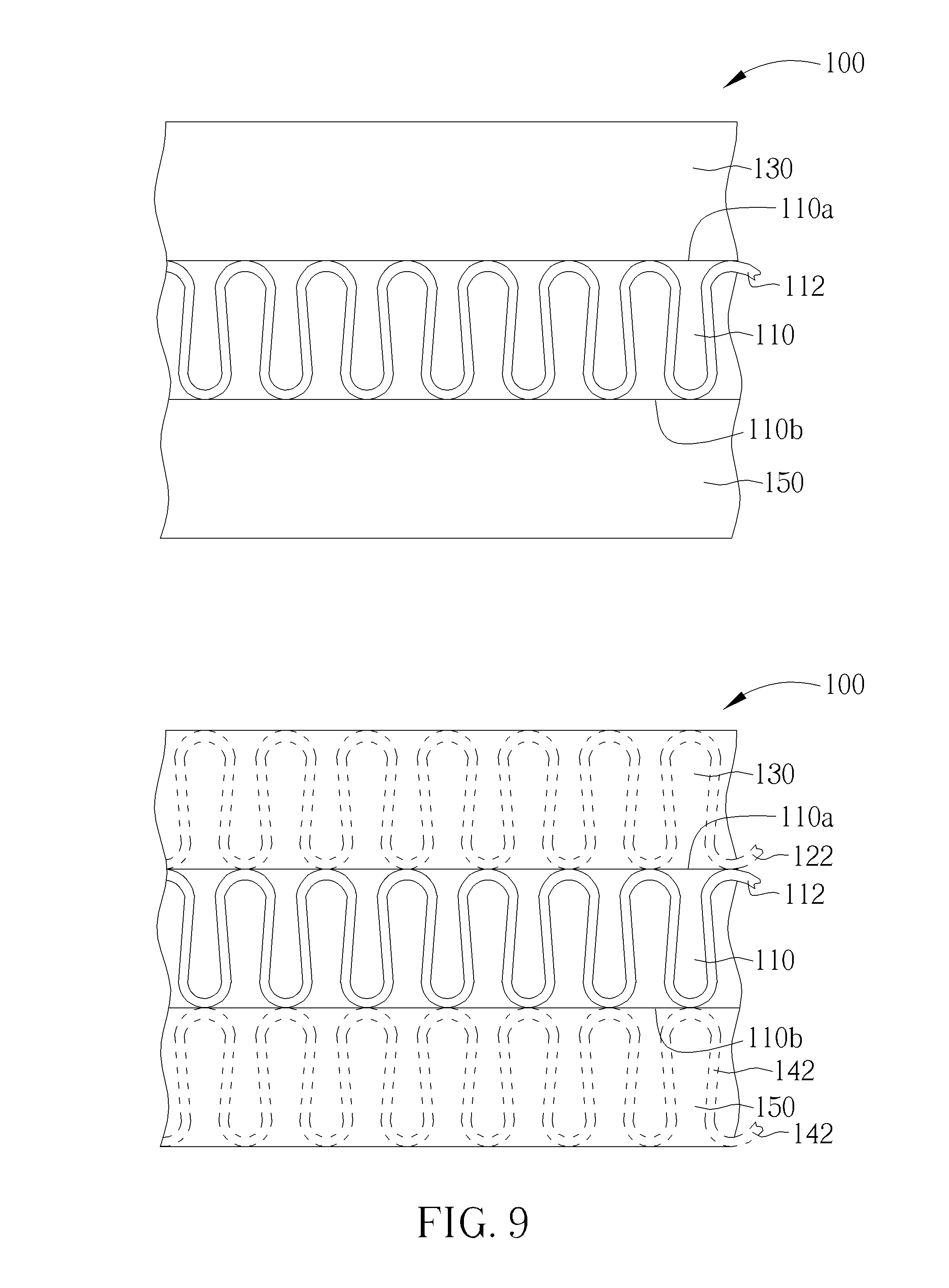
D00014
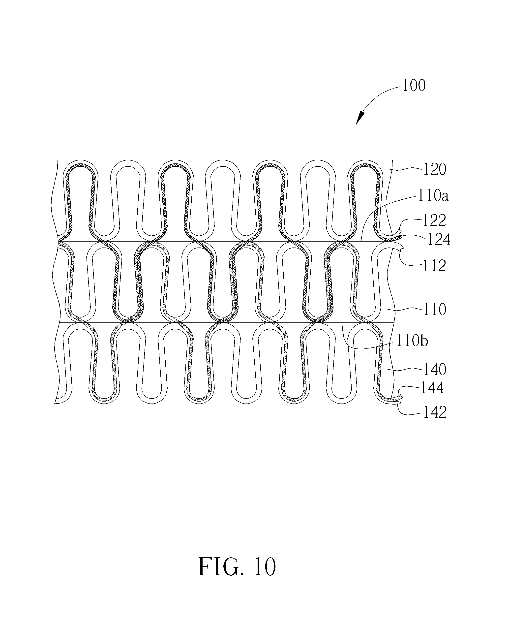
D00015
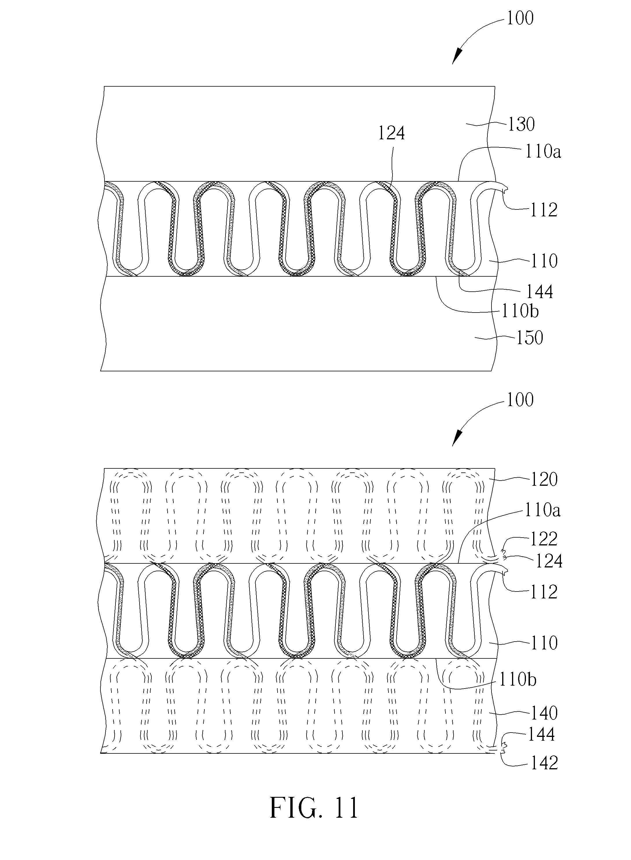
D00016
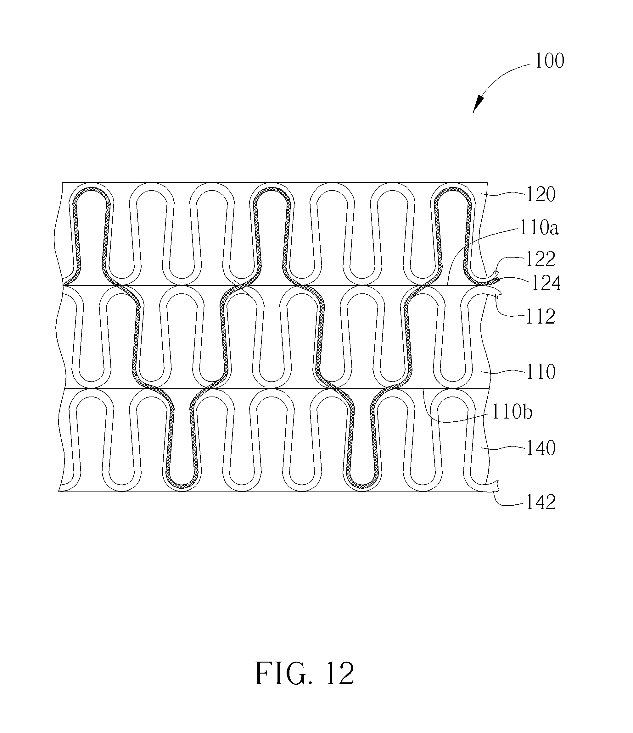
D00017
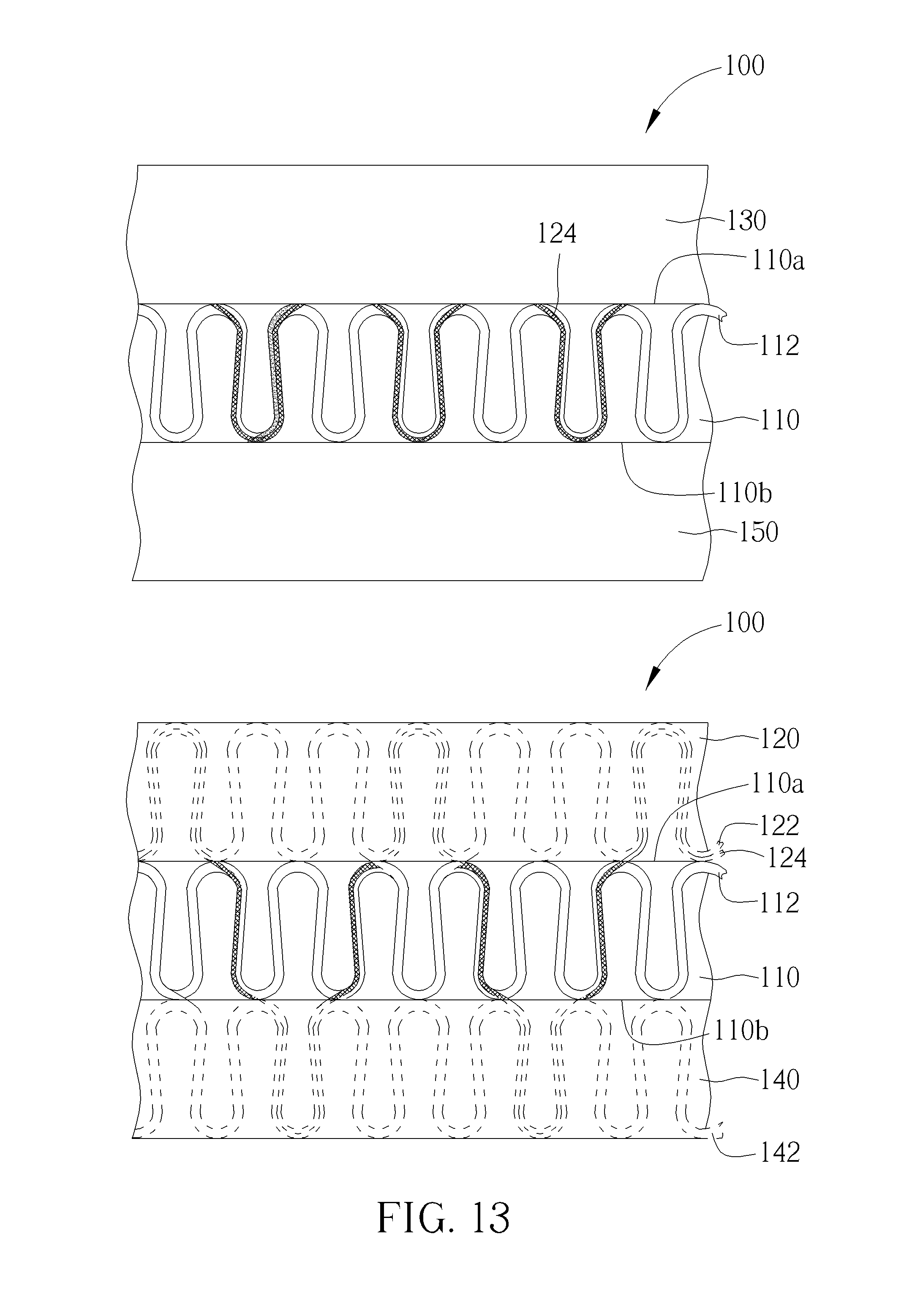
D00018
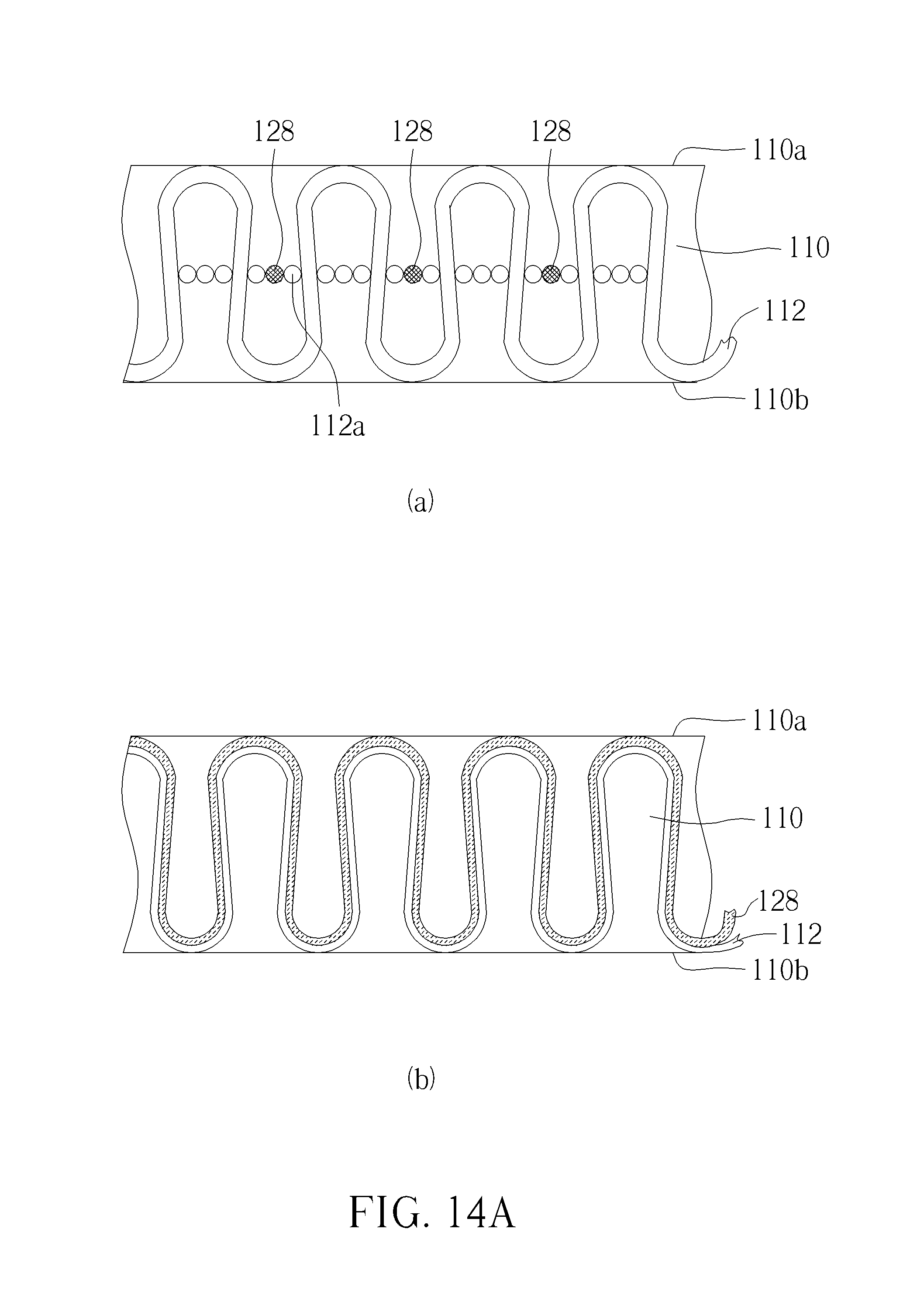
D00019
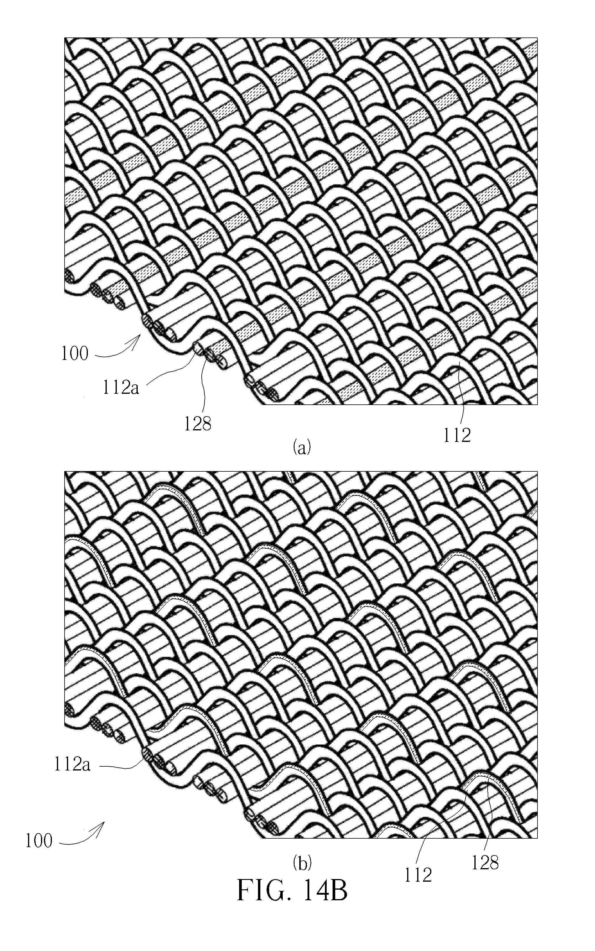
D00020
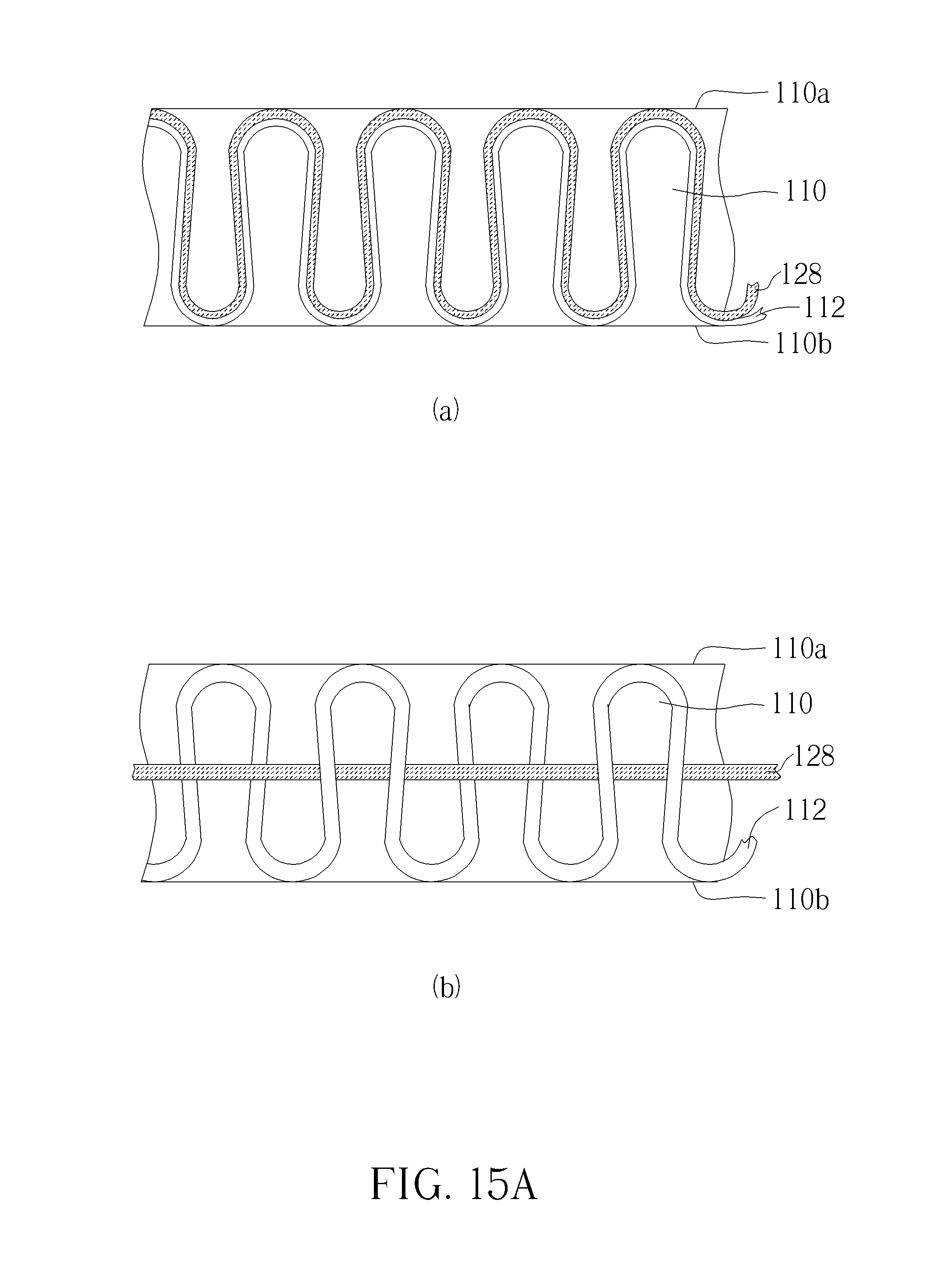
D00021
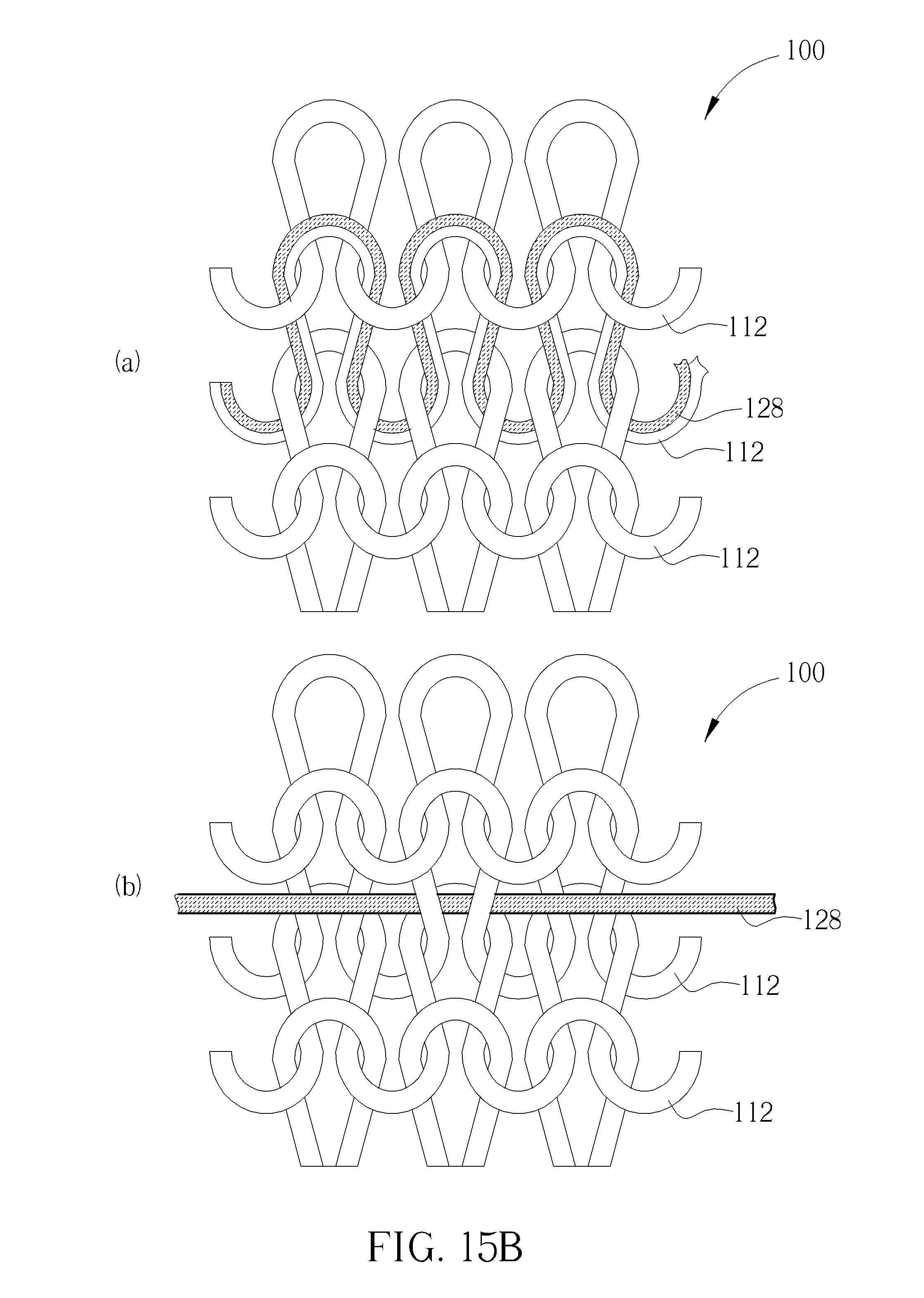
D00022
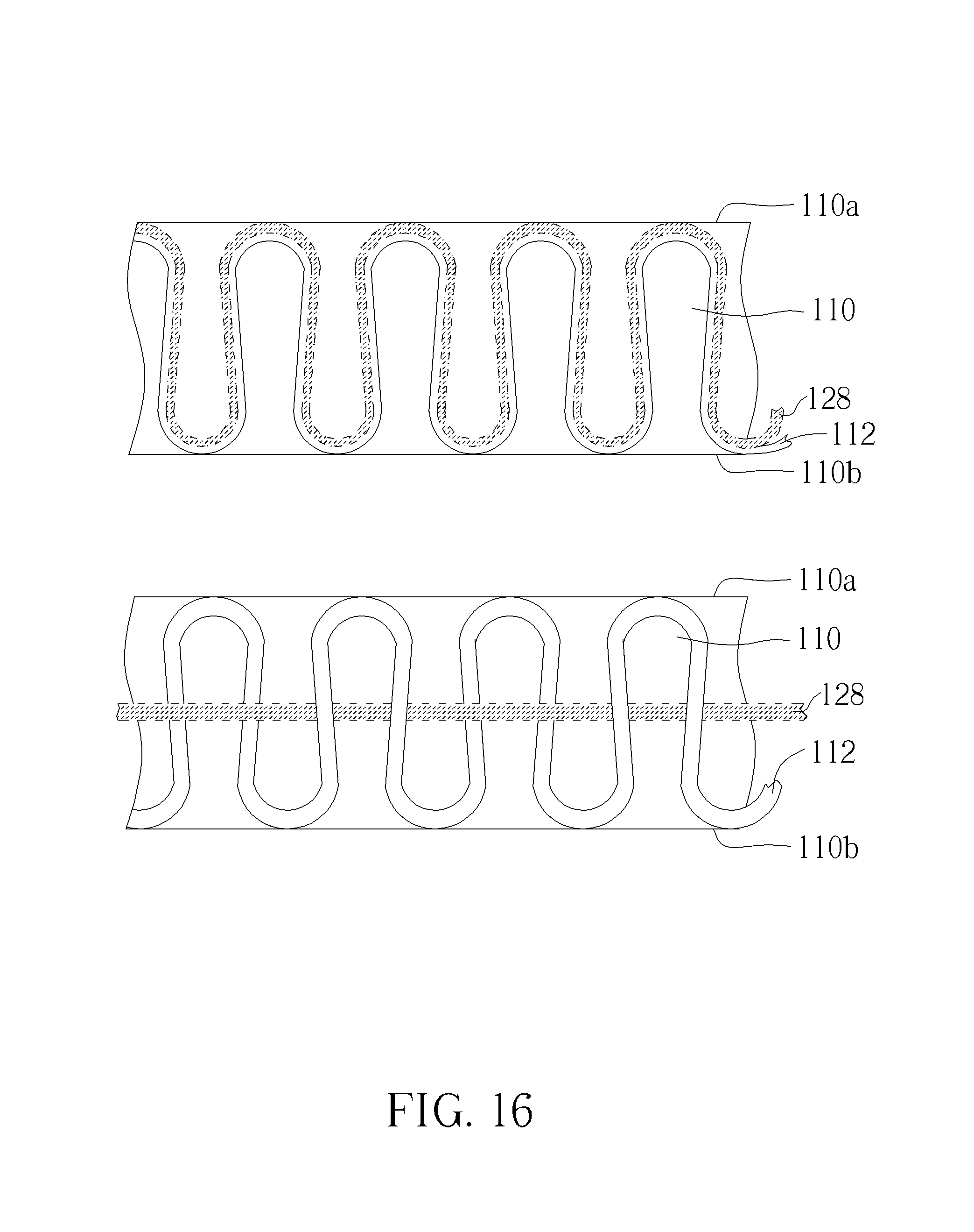
D00023
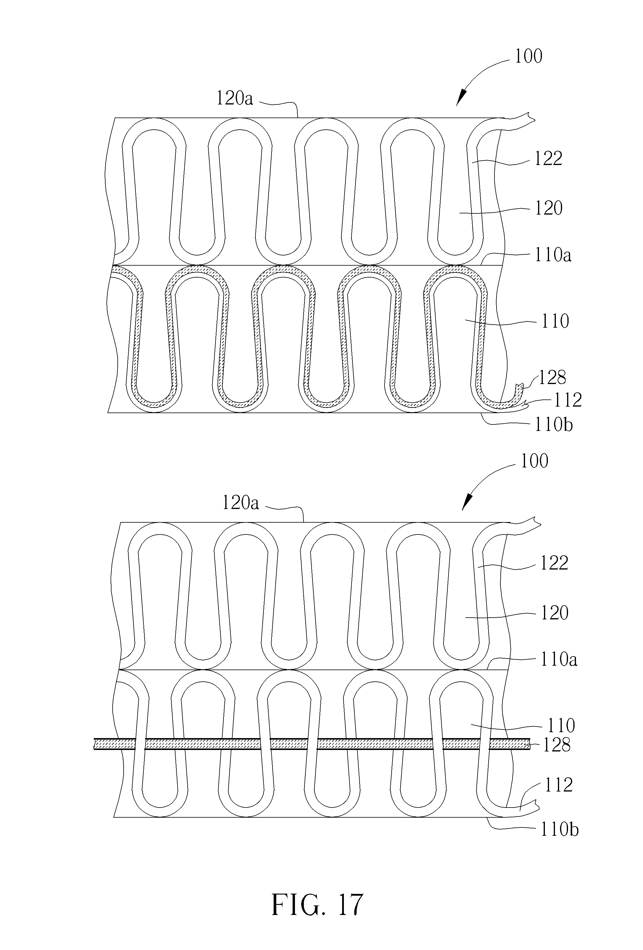
D00024

D00025

D00026

D00027

D00028
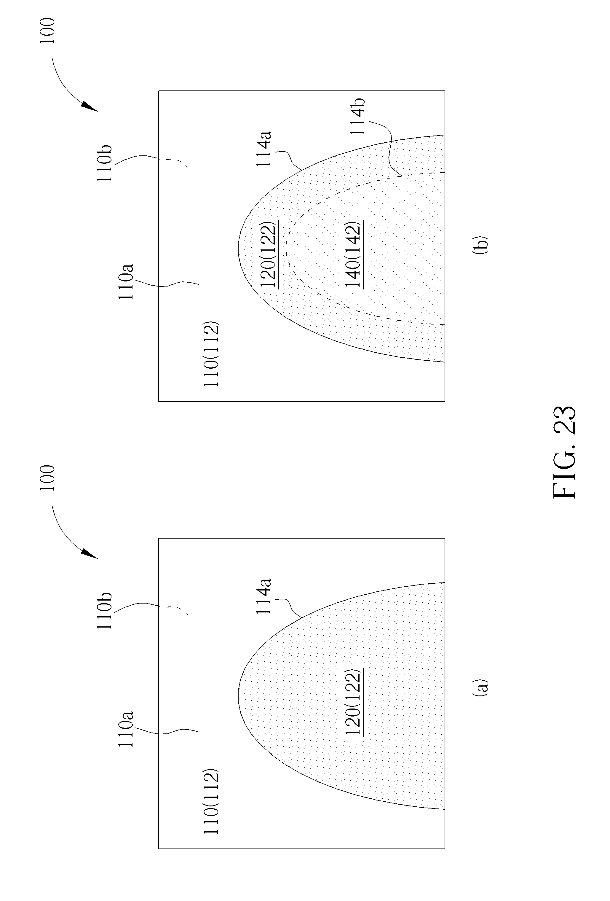
D00029
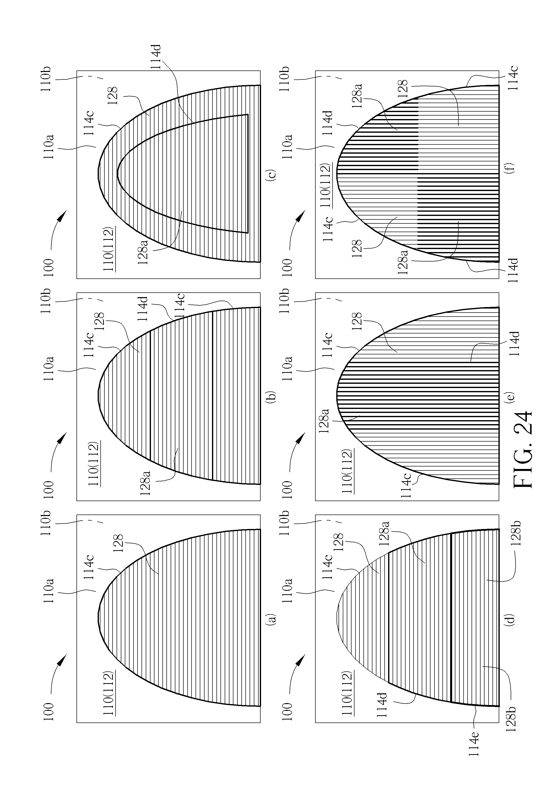
D00030
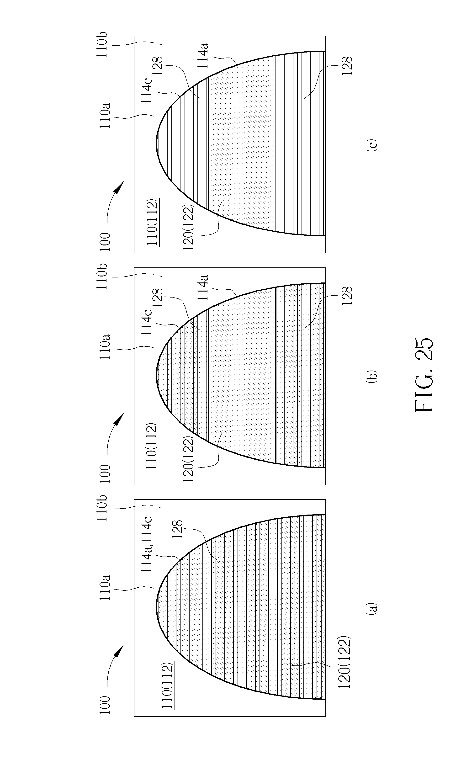
D00031

XML
uspto.report is an independent third-party trademark research tool that is not affiliated, endorsed, or sponsored by the United States Patent and Trademark Office (USPTO) or any other governmental organization. The information provided by uspto.report is based on publicly available data at the time of writing and is intended for informational purposes only.
While we strive to provide accurate and up-to-date information, we do not guarantee the accuracy, completeness, reliability, or suitability of the information displayed on this site. The use of this site is at your own risk. Any reliance you place on such information is therefore strictly at your own risk.
All official trademark data, including owner information, should be verified by visiting the official USPTO website at www.uspto.gov. This site is not intended to replace professional legal advice and should not be used as a substitute for consulting with a legal professional who is knowledgeable about trademark law.