H Section And Method For Manufacturing Same
MIZOGUCHI; Masaki ; et al.
U.S. patent application number 16/329163 was filed with the patent office on 2019-07-04 for h section and method for manufacturing same. This patent application is currently assigned to NIPPON STEEL & SUMITOMO METAL CORPORATION. The applicant listed for this patent is NIPPON STEEL & SUMITOMO METAL CORPORATION. Invention is credited to Kazutoshi ICHIKAWA, Masaki MIZOGUCHI, Tetsuya SEIKE, Hirokazu SUGIYAMA.
| Application Number | 20190203309 16/329163 |
| Document ID | / |
| Family ID | 62626651 |
| Filed Date | 2019-07-04 |


| United States Patent Application | 20190203309 |
| Kind Code | A1 |
| MIZOGUCHI; Masaki ; et al. | July 4, 2019 |
H SECTION AND METHOD FOR MANUFACTURING SAME
Abstract
This H section includes, as a chemical composition, C, Si, Mn, Nb, V, Ti, and N; in which the H section includes, as a metallographic structure, ferrite of 60 area % to less than 100 area %, an average grain size of this ferrite is 1 .mu.m to 30 .mu.m, a thickness of a flange is 20 mm to 140 mm, tensile yield stress is 385 MPa to 530 MPa, and Charpy absorbed energy at -20.degree. C. is 100 J or more.
| Inventors: | MIZOGUCHI; Masaki; (Tokyo, JP) ; ICHIKAWA; Kazutoshi; (Tokyo, JP) ; SUGIYAMA; Hirokazu; (Tokyo, JP) ; SEIKE; Tetsuya; (Tokyo, JP) | ||||||||||
| Applicant: |
|
||||||||||
|---|---|---|---|---|---|---|---|---|---|---|---|
| Assignee: | NIPPON STEEL & SUMITOMO METAL
CORPORATION Tokyo JP |
||||||||||
| Family ID: | 62626651 | ||||||||||
| Appl. No.: | 16/329163 | ||||||||||
| Filed: | December 21, 2017 | ||||||||||
| PCT Filed: | December 21, 2017 | ||||||||||
| PCT NO: | PCT/JP2017/045965 | ||||||||||
| 371 Date: | February 27, 2019 |
| Current U.S. Class: | 1/1 |
| Current CPC Class: | C21D 8/0226 20130101; B21B 1/088 20130101; C22C 38/001 20130101; C22C 38/46 20130101; C22C 38/00 20130101; C22C 38/28 20130101; C22C 38/04 20130101; C21D 2211/005 20130101; C22C 38/06 20130101; C22C 38/44 20130101; C22C 38/12 20130101; C21D 8/005 20130101; C22C 38/002 20130101; C22C 38/42 20130101; C21D 2211/001 20130101; C22C 38/26 20130101; C21D 2211/008 20130101; C22C 38/24 20130101; C22C 38/48 20130101; C22C 38/50 20130101; C22C 38/58 20130101; C22C 38/16 20130101; C22C 38/14 20130101; C22C 38/08 20130101; C22C 38/02 20130101 |
| International Class: | C21D 8/00 20060101 C21D008/00; C22C 38/02 20060101 C22C038/02; C22C 38/04 20060101 C22C038/04; C22C 38/00 20060101 C22C038/00; C22C 38/06 20060101 C22C038/06; C22C 38/14 20060101 C22C038/14; C22C 38/12 20060101 C22C038/12; C22C 38/08 20060101 C22C038/08; C22C 38/16 20060101 C22C038/16; C22C 38/42 20060101 C22C038/42; C22C 38/44 20060101 C22C038/44; C22C 38/46 20060101 C22C038/46; C22C 38/48 20060101 C22C038/48; C22C 38/50 20060101 C22C038/50 |
Foreign Application Data
| Date | Code | Application Number |
|---|---|---|
| Dec 21, 2016 | JP | 2016-248181 |
Claims
1. An H section, wherein a steel comprises, as a chemical composition, by mass %, C: 0.05% to 0.160%, Si: 0.01% to 0.60%, Mn: 0.80% to 1.70%, Nb: 0.005% to 0.050%, V: 0.05% to 0.120%, Ti: 0.001% to 0.025%, N: 0.0001% to 0.0120%, Cr: 0% to 0.30%, Mo: 0% to 0.20%, Ni: 0% to 0.50%, Cu: 0% to 0.35%, W: 0% to 0.50%, Ca: 0% to 0.0050%, Zr: 0% to 0.0050%, Al: limited to 0.10% or less, B: limited to 0.0003% or less, and a remainder including Fe and impurities, wherein C, Mn, Cr, Mo, V, Ni, and Cu in the chemical composition satisfy 0.30.ltoreq.Ceq.ltoreq.0.48, when Ceq=C+Mn/6+(Cr+Mo+V)/5+(Ni+Cu)/15, the steel includes, as a metallographic structure, by area fraction, ferrite of 60% to less than 100%, a mixed structure MA of martensite and austenite being limited to 3.0% or less, and a structure other than the ferrite and the MA being limited to 37% or less, an average grain size of the ferrite is 1 .mu.m to 30 .mu.m, a shape is an H-shape and a thickness of a flange is 20 mm to 140 mm, when being seen in a cut section orthogonal to a rolling direction, at a position of (1/6)F from an end surface of the flange in the width direction, tensile yield stress is 385 MPa to 530 MPa and maximum tensile strength is 490 MPa to 690 MPa, when a length of the flange in a width direction is F, and at the position of (1/6)F and at a position of (114)t.sub.2 from an outer surface of the flange in a thickness direction, absorbed energy in a Charpy test at -20.degree. C. is 100 J or more, when the thickness of the flange is t.sub.2.
2. The H section according to claim 1, comprising, as the chemical composition, by mass %, Nb: more than 0.02% to 0.050%.
3. The H section according to claim 1, comprising, as the chemical composition, by mass %, N: more than 0.005% to 0.0120%.
4. The H section according to claim 1, comprising, as the chemical composition, by mass %, Cu: limited to less than 0.03%.
5. The H section according to claim 1, comprising, as the chemical composition, by mass %, Al: limited to less than 0.003%.
6. The H section according to claim 1, wherein the thickness of the flange is 25 mm to 140 mm.
7. A method for manufacturing the H section according to claim 1, comprising: steelmaking to obtain a molten steel which has the chemical composition according to claim 1; casting the molten steel after the steelmaking to obtain a steel piece; heating the steel piece after the casting to 1,100.degree. C. to 1,350.degree. C.; hot rolling on the steel piece after the heating to form a shape, when being seen in a cut section orthogonal to a rolling direction, into an H-shape under conditions, wherein a cumulative rolling reduction at a position of (1/6)F from an end surface of a flange in a width direction within more than 900.degree. C. and 1,100.degree. C. or less is 20% or more, the cumulative rolling reduction at the position within 730.degree. C. to 900.degree. C. is 15% or more, and the rolling ends at 730.degree. C. or more; and cooling a hot rolled material after the hot rolling by natural cooling.
Description
TECHNICAL FIELD OF THE INVENTION
[0001] The present invention relates to a thick H section, which has excellent strength and low temperature toughness, and a method for manufacturing the same. Priority is claimed on Japanese Patent Application No. 2016-248181, filed on Dec. 21, 2016, the content of which is incorporated herein by reference.
RELATED ART
[0002] Recently, buildings such as high-rise buildings are becoming large and high, and thick steels have been utilized as strength members required for the structure. However, generally, in ferrous materials, as the thickness of a product increases, it becomes difficult to ensure the strength, and it is also difficult to ensure the toughness.
[0003] In regard to such a problem, in Patent Document 1, a technology of ensuring the toughness by utilizing an effect of refining prior austenite grains due to a Ca--Al-based oxide and obtaining a steel, in which high strength is ensured by applying accelerated cooling, is proposed.
[0004] In addition, in Patent Document 2, a technology of ensuring the toughness by utilizing the effect of refining prior austenite grains due to a Mg--S-based inclusion and obtaining a steel, in which high strength is ensured by applying accelerated cooling, is proposed.
[0005] However, when a thick steel plate is manufactured, if accelerated cooling is applied after hot rolling, the cooling rate becomes slow inside the steel plate compared to its surface, so that a significant difference is caused between the surface and the inside in the temperature history during cooling, and a difference is caused in mechanical properties such as strength, ductility, toughness, depending on a portion of a steel.
[0006] In addition, for large buildings, it is desired to use thick H sections. However, these H sections are unique in shape. Universal rolling and the like are applied to form a steel piece into an H-shape. However, rolling conditions (temperature and rolling reduction) are limited in universal rolling. Therefore, in a case where an H section is manufactured, particularly in a case where a thick H section having a thickness of a flange of 20 mm or more is manufactured, it is not easy to control mechanical properties compared to general thick steel plates (thick steel plates).
[0007] In regard to such a problem, in Patent Documents 3 and 4, methods of ensuring homogeneous mechanical properties of a steel piece by performing natural cooling after hot rolling of the steel piece, in which the amount of C is reduced and B is added, are proposed.
[0008] In addition, in Patent Documents 5 to 8, methods for manufacturing a thick H section or an H section for the purpose of high strength, high toughness, and the like are disclosed.
PRIOR ART DOCUMENT
Patent Document
[0009] [Patent Document 1] Japanese Patent No. 5655984
[0010] [Patent Document 2] Japanese Patent No. 5867651
[0011] [Patent Document 3] Japanese Unexamined Patent Application, First Publication No. 2003-328070
[0012] [Patent Document 4] Japanese Unexamined Patent Application, First Publication No. 2011-106006
[0013] [Patent Document 5] Japanese Unexamined Patent Application, First Publication No. H11-158543
[0014] [Patent Document 6] Japanese Unexamined Patent Application, First Publication No. H11-335735
[0015] [Patent Document 7] Japanese Unexamined Patent Application, First Publication No. 2016-84524
[0016] [Patent Document 8] Japanese Unexamined Patent Application, First Publication No. H10-68016
DISCLOSURE OF THE INVENTION
Problems to be Solved by the Invention
[0017] In the related art, in thick H sections having a thickness of a flange of 20 mm or more, it has not been easy to control mechanical properties. Therefore, such thick H sections have been required to satisfy toughness no more than at room temperature or at 0.degree. C. However, recently, in consideration of usage in a cold district and the like, thick H sections are required to have excellent toughness at a lower temperature. Furthermore, in consideration of strength per unit weight as structural materials, thick H sections are also required to have yield stress (specifically, yield strength or 0.2% proof stress) of 385 MPa or more.
[0018] The present invention has been made in consideration of such circumstances, and an object thereof is to provide a thick H section, which has excellent strength and low temperature toughness, and a method for manufacturing the same.
Means for Solving the Problem
[0019] The gist of the present invention is as follows.
[0020] (1) According to an aspect of the present invention, there is provided an H section; in which a steel includes, as a chemical composition, by mass %, C: 0.05% to 0.160%, Si: 0.01% to 0.60%, Mn: 0.80% to 1.70%, Nb: 0.005% to 0.050%, V: 0.05% to 0.120%, Ti: 0.001% to 0.025%, N: 0.0001% to 0.0120%, Cr: 0% to 0.30%, Mo: 0% to 0.20%, Ni: 0% to 0.50%, Cu: 0% to 0.35%, W: 0% to 0.50%, Ca: 0% to 0.0050%, Zr: 0% to 0.0050%, Al: limited to 0.10% or less, B: limited to 0.0003% or less, and a remainder including Fe and impurities; in which C, Mn, Cr, Mo, V, Ni, and Cu in the chemical composition satisfy 0.30.ltoreq.Ceq.ltoreq.0.48, when Ceq=C+Mn/6+(Cr+Mo+V)/5+(Ni+Cu)/15 is established; the steel includes, as a metallographic structure, by area fraction, ferrite of 60% to less than 100%, a mixed structure MA of martensite and austenite being limited to 3.0% or less, and a structure other than the ferrite and the MA being limited to 37% or less; an average grain size of the ferrite is 1 .mu.m to 30 .mu.m; a shape is an H-shape and a thickness of a flange is 20 mm to 140 mm, when being seen in a cut section orthogonal to a rolling direction; at a position of (1/6)F from an end surface of the flange in the width direction, tensile yield stress is 385 MPa to 530 MPa and maximum tensile strength is 490 MPa to 690 MPa, when a length of the flange in a width direction is F; and at the position of (1/6)F and at a position of (1/4)t.sub.2 from an outer surface of the flange in a thickness direction, absorbed energy in a Charpy test at -20.degree. C. is 100 J or more, when the thickness of the flange is t.sub.2.
[0021] (2) The H section according to (1) may include, as the chemical composition, by mass %, Nb: more than 0.02% to 0.050%.
[0022] (3) The H section according to (1) or (2) may include, as the chemical composition, by mass %, N: more than 0.005% to 0.0120%.
[0023] (4) The H section according to any one of (1) to (3) may include, as the chemical composition, by mass %, Cu: limited to less than 0.03%.
[0024] (5) The H section according to any one of (1) to (4) may include, as the chemical composition, by mass %, Al: limited to less than 0.003%.
[0025] (6) In the H section according to any one of (1) to (5), the thickness of the flange may be 25 mm to 140 mm.
[0026] (7) According to another aspect of the present invention, there is provided a method for manufacturing the H section according to any one of (1) to (6), including steelmaking to obtain a molten steel which has the chemical composition according to any one of (1) to (5); casting the molten steel after the steelmaking to obtain a steel piece; heating the steel piece after the casting to 1,100.degree. C. to 1,350.degree. C.; hot rolling on the steel piece after the heating to form a shape, when being seen in a cut section orthogonal to a rolling direction, into an H-shape under conditions, in which a cumulative rolling reduction at a position of (1/6)F from an end surface of a flange in a width direction is 20% or more within more than 900.degree. C. and 1,100.degree. C. or less, the cumulative rolling reduction at the position is 15% or more within 730.degree. C. to 900.degree. C., and the rolling ends at 730.degree. C. or more; and cooling a hot rolled material after the hot rolling by natural cooling.
Effects of the Invention
[0027] According to the aspect of the present invention, it is possible to provide a thick H section, which has excellent strength and low temperature toughness, and a method for manufacturing the same.
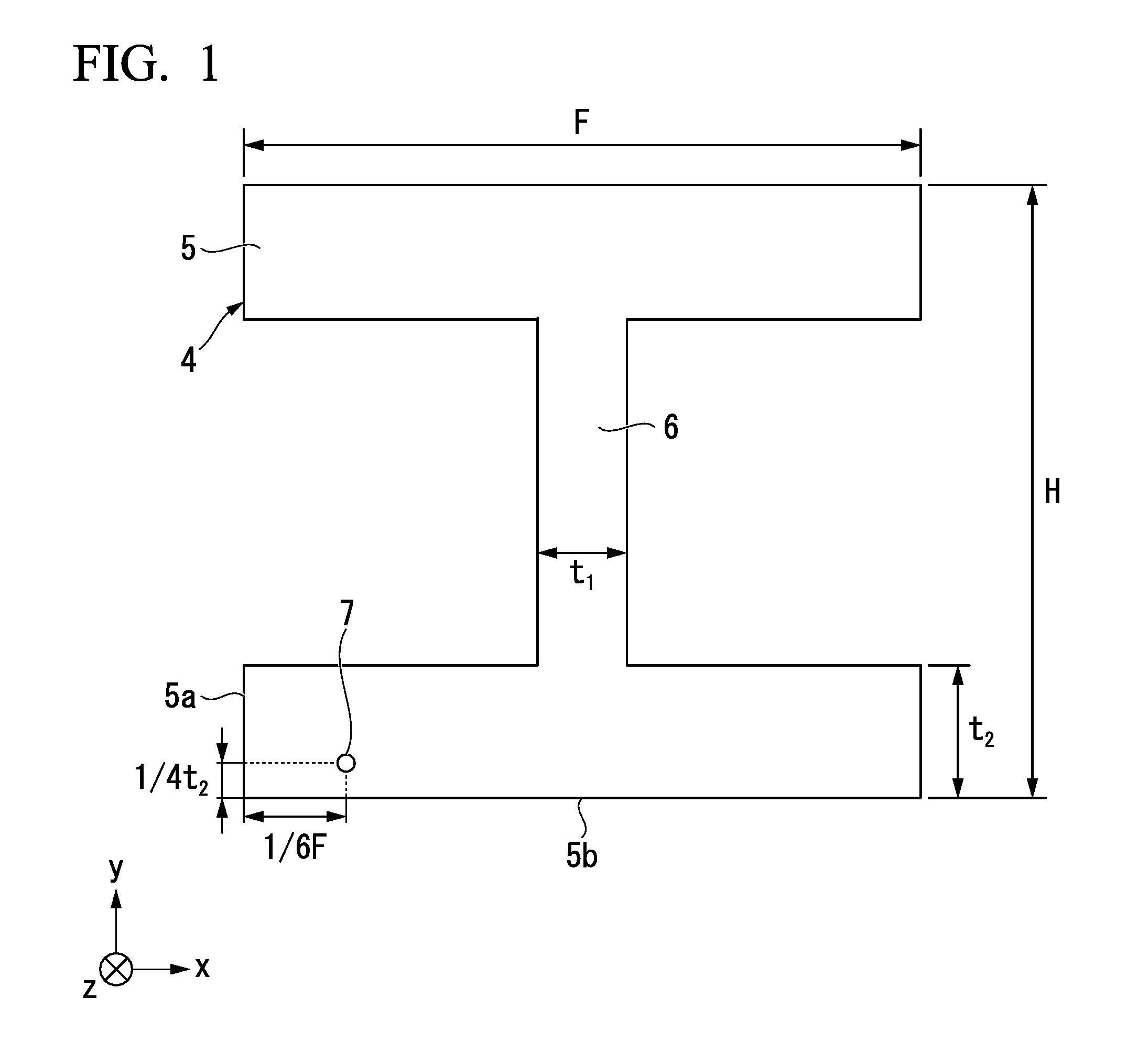
BRIEF DESCRIPTION OF THE DRAWINGS
[0028] FIG. 1 is a schematic cross-sectional view explaining a position at which a test piece of an H section according to an embodiment of the present invention is collected.
[0029] FIG. 2 is a flowchart showing a method for manufacturing an H section according to the embodiment of the present invention.
EMBODIMENT OF THE INVENTION
[0030] Hereinafter, a suitable embodiment of the present invention will be described in detail. However, the present invention is not limited to only the configurations disclosed in the present embodiment, and various changes can be made within a range not departing from the gist of the present invention. In addition, in the following numerical limitation ranges, the lower limit value and the upper limit value are included in the range thereof. In numerical values expressed with "more than" or "less than", the value is not included in the numerical value range thereof. The symbol "%" related to the amount of each element means "mass %".
[0031] As described above, until now, thick H sections having a thickness of a flange of 20 mm or more have been required to satisfy toughness no more than at room temperature or at 0.degree. C. However, currently, in consideration of usage in a cold district and the like, thick H sections are required to have excellent toughness at a lower temperature, such as approximately -20.degree. C. Furthermore, in consideration of strength per unit weight as structural materials, thick H sections are also required to have yield stress (specifically, yield strength or 0.2% proof stress) of 385 MPa or more.
[0032] Therefore, in regard to a thick H section (there may hereinafter be a case where it is disclosed as a steel), particularly in regard to a flange which is an important portion in the structure of an H section, the inventors have found the following knowledge by investigating a steel composition (a chemical composition of a steel) affecting the strength and the low temperature toughness, and the influence of a steel structure (a metallographic structure of a steel). In the present embodiment, strength means tensile yield stress and the maximum tensile strength, and low temperature toughness means absorbed energy in a Charpy test at -20.degree. C.
[0033] First, an excessively increase in hardenability caused by adding an alloying element encourages the generation of a martensite-austenite mixed structure (hereinafter, it will be disclosed as an MA) in a steel, and which leads to deterioration in low temperature toughness. Particularly, since B in an alloying element noticeably tends to encourage the generation of an MA, it is effective that B is not actively added and is limited to the level of impurities or less.
[0034] In addition, in order to realize the high yield stress (yield strength or 0.2% proof stress) and to improve the toughness at -20.degree. C. at the same time, it is effective that Nb is added. Since Nb increases the strength of a steel through precipitation strengthening, there is no need to excessively increase the hardenability, and strength of a steel can be increased without encouraging the generation of an MA. In addition, Nb has effects of suppressing recrystallization of austenite during hot rolling, accumulating strain in a steel caused through rolling, and bringing grain refinement of ferrite after transformation.
[0035] In addition, in order to improve the toughness at -20.degree. C., it is effective that V is added. V has effects of being precipitated as carbonitride (VC, VN, or a composite thereof), functioning as a nucleation site of ferrite, and bringing grain refinement of ferrite.
[0036] In addition, when Mn is added, strength and low temperature toughness are further improved. Furthermore, for achieving both the high strength and the low temperature toughness, it is important to control the area fraction of ferrite, the area fraction of MA, the average grain size of ferrite, and the like as the steel structure after the steel composition is controlled.
[0037] In order to stably control a steel structure, when hot rolling a steel piece in which the steel composition is controlled, it is necessary to apply sufficient rolling strain to each of a recrystallization temperature range and a non-recrystallization temperature range of austenite. Specifically, in a temperature range of more than 900.degree. C. and 1,100.degree. C. or less, hot rolling in which the cumulative rolling reduction is 20% or more is performed. Moreover, in a temperature range of 900.degree. C. or less, hot rolling in which the cumulative rolling reduction is 15% or more is performed. Through rolling at a temperature more than 900.degree. C., austenite grains are subjected to grain refinement to deteriorate the hardenability, so that the generation amount of an MA, and the like are kept low. Through rolling at 900.degree. C. or less, ferrite is subjected to grain refinement by applying a large amount of strain to the inside of a steel so as to increase the frequency of nucleation of ferrite.
[0038] In addition, in order to stably control a steel structure, when cooling after hot rolling, it is preferable to have a small difference between the cooling rates of a surface of a steel and inside thereof. In a case where a steel is natural cooled without accelerated cooling after hot rolling, the cooling rate is decreased in both a surface and the inside of the steel, so that the difference therebetween is also reduced. For example, in an H section having a thickness of a flange of 20 mm, if a steel is subjected to natural cooling after hot rolling, both the average cooling rates from 800.degree. C. to 500.degree. C. of a surface of a steel and inside thereof become 1.degree. C./sec or less.
[0039] In a case where the cooling rate after hot rolling is slow, generally, it is not easy to ensure the yield stress and the low temperature toughness at the same time. However, both the yield stress and the low temperature toughness can be achieved by optimally controlling the steel composition and manufacturing conditions. For example, as a steel composition, the C content is 0.05% to 0.160%, B is not added and is limited to the level of impurities or less, Nb and V are actively added, the amounts of the alloying elements such as Mn, Ti, and N are appropriately controlled, and a carbon equivalent Ceq is controlled to be a range of 0.30 to 0.48. Furthermore, as the steel structure, the area fraction of ferrite, the area fraction of MA, the average grain size of ferrite, and the like are elaborated by optimally controlling the manufacturing conditions. As a result, a thick H section having excellent strength and low temperature toughness can be obtained.
[0040] Hereinafter, an H section according to the present embodiment will be described. First, the steel composition and reasons for limiting numerical ranges will be described in detail.
[0041] The H section according to the present embodiment includes, as a chemical composition, base elements and includes optional elements as necessary. The remainder includes Fe and impurities.
[0042] In the chemical composition of the H section according to the present embodiment, C, Si, Mn, Nb, V, Ti, and N are the base elements (main alloying elements).
[0043] (C: 0.05% to 0.160%)
[0044] C (Carbon) is an element which is effective for strengthening of a steel. Therefore, the lower limit for the C content is set to 0.05%. Preferably, the lower limit for the C content is set to 0.060%, 0.070%, or 0.080%. On the other hand, when the C content exceeds 0.160%, and which leads to deterioration in low temperature toughness. Therefore, the upper limit for the C content is set to 0.160%. In order to further improve the low temperature toughness, the upper limit for the C content is preferably set to 0.140%, 0.130%, or 0.120%.
[0045] (Si: 0.01% to 0.60%)
[0046] Si (Silicon) is a deoxidizing element and is an element which also contributes to improvement of strength. Therefore, the lower limit for the Si content is set to 0.01%. Preferably, the lower limit for the Si content is set to 0.05%, 0.10%, or 0.15%. On the other hand, when the Si content exceeds 0.60%, the generation of an MA is encouraged, and which leads to deterioration in low temperature toughness. Therefore, the upper limit for the Si content is set to 0.60%. In order to further improve the low temperature toughness, the upper limit for the Si content is preferably set to 0.40% or 0.30%.
[0047] (Mn: 0.80% to 1.70%)
[0048] Mn (Manganese) is an element which contributes to improvement of strength. Therefore, the lower limit for the Mn content is set to 0.80%. In order to further increase the strength, the lower limit for the Mn content is preferably set to 1.0%, 1.1%, or 1.2%. On the other hand, when the Mn content exceeds 1.70%, the hardenability is excessively increased, generation of an MA is encouraged, and the low temperature toughness is impaired. Therefore, the upper limit for the Mn content is set to 1.70%. Preferably, the upper limit for the Mn content is set to 1.60% or 1.50%.
[0049] (Nb: 0.005% to 0.050%)
[0050] Nb (Niobium) is an element which suppresses recrystallization of austenite at the time of hot rolling, contributes to grain refinement of ferrite by accumulating work strain in a steel, and contributes to improvement of strength through precipitation strengthening. Therefore, the lower limit for the Nb content is set to 0.005%. Preferably, the lower limit for the Nb content is set to 0.010%, more than 0.020%, 0.025%, or 0.030%. However, when the Nb content exceeds 0.050%, and which may lead to significant deterioration in low temperature toughness. Therefore, the upper limit for the Nb content is set to 0.050%. Preferably, the upper limit for the Nb content is set to 0.045%, 0.043%, or 0.040%. In a case where Nb is not intentionally added, the Nb content included as an impurity is set to less than 0.005%. In order to set the Nb content to 0.005% or more, Nb is intentionally included in a steel.
[0051] (V: 0.05% to 0.120%)
[0052] V (Vanadium) is an element which has effects of being precipitated as carbonitride inside grains of austenite, acting as transformation nuclei with respect to ferrite, and refining ferrite grains. Therefore, the lower limit for the V content is set to 0.05%. Preferably, the lower limit for the V content is set to more than 0.05%, 0.06%, or 0.07%. However, when the V content exceeds 0.120%, the low temperature toughness may be impaired by coarsening precipitates. Therefore, the upper limit for the V content is set to 0.120%. Preferably, the upper limit for the V content is set to 0.110% or 0.100%.
[0053] (Ti: 0.001% to 0.025%)
[0054] Ti (Titanium) is an element which forms TiN and fixes N in a steel. Therefore, the lower limit for the Ti content is set to 0.001%. In order to further refine austenite due to a pinning effect of TiN, the lower limit for the Ti content is preferably set to 0.005%, 0.007%, or 0.010%. On the other hand, when the Ti content exceeds 0.025%, coarse TiN is generated and the low temperature toughness is impaired. Therefore, the upper limit for the Ti content is set to 0.025%. Preferably, the upper limit for the Ti content is set to 0.020%, 0.015%, or 0.012%.
[0055] In addition, in a case where Al is not actively added, Ti serves as a deoxidizing element, thereby remaining N which is not bonded to Ti. However, this N is precipitated as V carbonitride having Ti oxide as nuclei. That is, since Ti serves as a deoxidizing element and Ti oxide is precipitated, precipitation of V carbonitride is promoted, and low temperature toughness can be improved.
[0056] (N: 0.0001% to 0.0120%)
[0057] N (Nitrogen) is an element which forms TiN or VN and contributes to grain refinement of a structure or precipitation strengthening. Therefore, the lower limit for the N content is set to 0.0001%. Preferably, the lower limit for the N content is set to 0.0020%, 0.0035%, more than 0.0050%, or 0.0060%. However, when the N content exceeds 0.0120%, the low temperature toughness is deteriorated, and surface cracking at the time of casting or material defect due to strain aging of a manufactured steel is caused. Therefore, the upper limit for the N content is set to 0.0120%. Preferably, the upper limit for the N content is set to 0.0110%, 0.0100%, or 0.0090%.
[0058] The H section according to the present embodiment contains impurities as a chemical composition. "Impurities" indicate elements incorporated from ore or scrap as a raw material, or the manufacturing environment, when a steel is industrially manufactured. For example, impurities mean elements such as Al, B, P, S, and O. In these impurities, it is preferable that Al and B are limited as follows in order to sufficiently exhibit the effects of the present embodiment. In addition, since it is preferable that the amounts of impurities are small, there is no need to limit the lower limit value, and the lower limit value for impurities may be 0%.
[0059] (Al: 0.10% or less)
[0060] Al (Aluminum) is an element used as a deoxidizing element. However, when the Al content exceeds 0.10%, oxide is coarsened and becomes origins of brittle fracture, so that low temperature toughness is deteriorated. Therefore, the upper limit for the Al content is limited to 0.10%. In addition, in a case where Al is not actively used as a deoxidizing element, Ti serves as the deoxidizing element, and Ti oxide is precipitated in a steel. This Ti oxide functions as a nucleation site of V carbonitride, refines the grain size of ferrite, and contributes to improvement of low temperature toughness. Therefore, the upper limit for the Al content may be limited to less than 0.003%, 0.002%, or 0.001% in a case of including Al as impurities, instead of using Al as a deoxidizing element. Generally, in order to set the Al content to 0.003% or more, Al is intentionally included in a steel.
[0061] (B: 0.0003% or less)
[0062] B (Boron) increases the hardenability, encourages the generation of an MA, and deteriorates the low temperature toughness. Therefore, in the present embodiment, B is not actively added and is limited to the level of impurities or less. The upper limit for the B content is limited to 0.0003%. Preferably, the upper limit for the B content is limited to less than 0.0003%, 0.0002%, or 0.0001%. Generally, in order to set the B content to more than 0.0003%, B is intentionally included in a steel.
[0063] (P: 0.03% or less, S: 0.02% or less, and 0: 0.005% or less)
[0064] P (Phosphorus), S (Sulfur), and 0 (Oxygen) are impurities. P and S encourage the weld cracking through solidifying segregation and deteriorates the low temperature toughness. Preferably, the upper limit for the P content is limited to 0.03%, 0.02%, or 0.01%. In addition, preferably, the upper limit for the S content is limited to 0.02% or 0.01%. O deteriorates the low temperature toughness by being solid-solubilized in a steel, and deteriorates the low temperature toughness through coarsening of oxide particles. Preferably, the upper limit for the O content is limited to 0.005%, 0.004%, or 0.003%.
[0065] In addition to the base elements and the impurities described above, the H section according to the present embodiment may contain optional elements. For example, instead of a part of Fe which is the remainder as described above, Cr, Mo, Ni, Cu, W, Ca, Zr, Mg, and/or REM may be contained as optional elements. These optional elements may be contained in accordance with their purpose. Thus, there is no need to limit the lower limit values for these optional elements, and the lower limit values may be 0%. In addition, even if these optional elements are contained as impurities, the foregoing effects are not impaired.
[0066] (Cr: 0% to 0.30%)
[0067] Cr (Chromium) is an element which contributes to improvement of strength. As necessary, the Cr content may be 0% to 0.30%. In order to further improve the strength, the lower limit for the Cr content is preferably set to 0.01%, 0.05%, or 0.10%. On the other hand, when the Cr content exceeds 0.30%, the generation of an MA may be encouraged and the low temperature toughness may be deteriorated. Therefore, preferably, the upper limit for the Cr content is set to 0.30%, 0.25%, or 0.20%.
[0068] (Mo: 0% to 0.20%)
[0069] Mo (Molybdenum) is an element which is solid-solubilized in a steel and contributes to improvement of strength. As necessary, the Mo content may be 0% to 0.20%. In order to further improve the strength, the lower limit for the Mo content is preferably set to 0.01%, 0.05%, or 0.10%. However, when the Mo content exceeds 0.20%, the generation of an MA may be encouraged, and which may lead to deterioration in low temperature toughness. Therefore, the upper limit for the Mo content is preferably set to 0.20%, 0.17%, or 0.15%.
[0070] (Ni: 0% to 0.50%)
[0071] Ni (Nickel) is an element which is solid-solubilized in a steel and contributes to improvement of strength. As necessary, the Ni content may be 0% to 0.50%. In order to further improve the strength, the lower limit for the Ni content is preferably set to 0.01%, 0.05%, or 0.10%. However, when the Ni content exceeds 0.50%, the hardenability may be increased, the generation of an MA may be encouraged, and the low temperature toughness may be deteriorated. Therefore, the upper limit for the Ni content is preferably set to 0.50%, 0.30%, or 0.20%.
[0072] (Cu: 0% to 0.35%)
[0073] Cu (Copper) is an element which contributes to improvement of strength. As necessary, the Cu content may be 0% to 0.35%. However, addition of Cu may encourage the generation of an MA and may deteriorate the low temperature toughness. Therefore, preferably, the Cu content is limited to 0.30% or less, 0.20% or less, or 0.10% or less. Alternatively, the Cu content may be limited to less than 0.03% or less than 0.01% which is the level of impurities.
[0074] (W: 0% to 0.50%)
[0075] W (Tungsten) is an element which is solid-solubilized in a steel and contributes to improvement of strength. As necessary, the W content may be 0% to 0.50%. Preferably, the lower limit for the W content is set to 0.001%, 0.01%, or 0.10%. However, when the W content exceeds 0.50%, the generation of an MA may be encouraged and the low temperature toughness may be deteriorated. Therefore, preferably, the upper limit for the W content is set to 0.50%, 0.40%, or 0.30%. In a case where W is not intentionally added, the W content included as an impurity is set to less than 0.001%. In order to set the W content to 0.001% or more, W is intentionally included in a steel.
[0076] (Ca: 0% to 0.0050%)
[0077] Ca (Calcium) is an element which is effective for controlling the form of sulfide, suppresses generation of coarse MnS, and contributes to improvement of low temperature toughness. As necessary, the Ca content may be set 0% to 0.0050%. Preferably, the lower limit for the Ca content is set to 0.0001%, 0.0005%, or 0.0010%. On the other hand, when the Ca content exceeds 0.0050%, the low temperature toughness may be deteriorated. Therefore, preferably, the upper limit for the Ca content is set to 0.0050%, 0.0040%, or 0.0030%.
[0078] (Zr: 0% to 0.0050%)
[0079] Zr (Zirconium) is an element which is precipitated as carbide, nitride, or a composite thereof and contributes to precipitation strengthening. As necessary, the Zr content may be set 0% to 0.0050%. Preferably, the lower limit for the Zr content is set to 0.0001%, 0.0005%, or 0.0010%. On the other hand, when the Zr content exceeds 0.0050%, carbide or nitride of Zr may be coarsened and the low temperature toughness may be deteriorated. Therefore, preferably, the upper limit for the Zr content is set to 0.0050%, 0.0040%, or 0.0030%. In a case where Zr is not intentionally added, the Zr content included as an impurity is set to less than 0.0001%. In order to set the Zr content to 0.0001% or more, Zr is intentionally included in a steel.
[0080] (Mg: 0% to 0.0050%, and REM: 0% to 0.0050%)
[0081] Mg (Magnesium) and REM (rare earth metal) are elements which contribute to improvement of toughness of a base material or toughness of a welded heat-affected zone (HAZ). As necessary, the Mg content may be 0% to 0.0050%, and the REM content may be 0% to 0.0050%. Preferably, the lower limit for the Mg content is set to 0.0005%, 0.0010%, or 0.0020%, and the lower limit for the REM content is set to 0.0005%, 0.0010%, or 0.0020%. On the other hand, preferably, the upper limit for the Mg content is set to 0.0040%, 0.0030%, or 0.0025%, and the upper limit for the REM content is set to 0.0040%, 0.0030%, or 0.0025%.
[0082] (Ceq: 0.30 to 0.48)
[0083] In the H section according to the present embodiment, from the view of ensuring the strength, the carbon equivalent Ceq is controlled. Specifically, when the Ceq is set as the following Expression 1, C, Mn, Cr, Mo, V, Ni, and Cu, by mass %, in the chemical composition of an H section satisfy 0.30.ltoreq.Ceq.ltoreq.0.48. If the Ceq is less than 0.30, strength becomes insufficient. Therefore, the lower limit for Ceq is set to 0.30. Preferably, the lower limit for Ceq is set to 0.32%, 0.34%, or 0.35%. On the other hand, when Ceq exceeds 0.48, the low temperature toughness is deteriorated. Therefore, the upper limit for Ceq is set to 0.48. Preferably, the upper limit for Ceq is set to 0.45%, 0.43%, or 0.40%. When the Ceq is calculated by the following Expression 1, the Ceq may be calculated by substituting 0 for the value in Expression 1, for an element in which the amount in a steel is equal to or less than a detection limit
Ceq=C+Mn/6+(Cr+Mo+V)/5+(Ni+Cu)/15 (Expression 1)
[0084] The steel composition described above may be measured by a general analysis method for a steel. For example, the steel composition may be measured by using ICP-AES (inductively coupled plasma-atomic emission spectrometry). C and S may be measured by using a combustion-infrared absorption method, N may be measured by using an inert gas fusion-thermal conductivity method, and O may be measured by using an inert gas fusion-non dispersive infrared absorption method.
[0085] Next, the steel structure and reasons for limiting numerical ranges of the H section according to the present embodiment will be described in detail.
[0086] In the H section according to the present embodiment, the steel structure includes ferrite of 60% to less than 100% by area fraction, a mixed structure MA of martensite and austenite being limited to 3.0% or less, and a structure other than ferrite and the MA being limited to 37% or less. In addition, the average grain size of ferrite is set to 1 .mu.m or more and 30 .mu.m or less.
[0087] (Area Fraction of ferrite: 60% to less than 100%)
[0088] Ferrite is a main constituent phase in the steel structure of the H section according to the present embodiment. If the area fraction of ferrite is less than 60%, low temperature toughness is deteriorated. Therefore, the lower limit for the ferrite fraction is set to 60%. Preferably, the lower limit for the ferrite fraction is set to 65%, 70%, or 75%. On the other hand, controlling the area fraction of ferrite to 100% is physically difficult because it involves formation of pearlite or bainite. Therefore, the upper limit for the ferrite fraction is set to less than 100%. In order to preferably control the strength and the low temperature toughness, the upper limit for the ferrite fraction is preferably set to 90%, 85%, or 80%.
[0089] (Area Fraction of MA: 3.0% or less)
[0090] If generation of an MA is encouraged, low temperature toughness is deteriorated. In the H section according to the present embodiment, strength of a steel is increased without encouraging the generation of an MA. Therefore, the MA fraction is limited to 3.0% or less. Preferably, the upper limit for the MA fraction is set to 2.5%, 2.0%, or 1.5%. The smaller the MA fraction, the more preferable. Therefore, the lower limit for the MA fraction may be 0%.
[0091] (Area Fraction of Structure Other than ferrite and MA: 37% or less)
[0092] The steel structure of the H section according to the present embodiment includes bainite, pearlite, and the like as structures other than the ferrite and the MA, as described above. If a structure other than ferrite and an MA is excessively included, low temperature toughness is deteriorated. Therefore, the area fraction of a structure other than ferrite and an MA (the remainder of ferrite and an MA, as described above) is limited to 37% or less. Preferably, the fraction of a structure other than ferrite and an MA is set to 35% or less, 30% or less, or 25% or less. The smaller the fraction of a structure other than ferrite and an MA, the more preferable. Therefore, the lower limit therefor may be 0%.
[0093] (Average Grain Size of ferrite: 1 .mu.m to 30 .mu.m)
[0094] It is preferable that an average grain size of ferrite is refined. When the grain size of ferrite exceeds 30 .mu.m, the low temperature toughness is deteriorated. Therefore, the upper limit for the grain size of ferrite is set to 30 .mu.m. Preferably, the upper limit for the grain size of ferrite is set to 25 .mu.m, 22 .mu.m, or 18 .mu.m. On the other hand, it is industrially difficult to control the grain size of ferrite to be less than 1 .mu.m. Therefore, the lower limit for the grain size of ferrite is set to 1 .mu.m. Preferably, the lower limit for the grain size of ferrite is set to 3 .mu.m, 5 .mu.m, or 10 .mu.m.
[0095] The steel structure described above may be discriminated through observation using an optical microscope. For example, FIG. 1 is a schematic cross-sectional view orthogonal to a rolling direction of an H section. However, the steel structure is observed by setting a portion in the vicinity of an evaluation portion 7 illustrated in FIG. 1 as an observed section. Specifically, in FIG. 1, the steel structure is observed by setting a portion in the vicinity of the evaluation portion 7 at a position of (1/6)F from an end surface 5a of a flange in a width direction and a position of (1/4)t.sub.2 from an outer surface 5b of the flange in a thickness direction, as the observed section. This observed section is a section parallel to the end surface 5a of the flange in the width direction.
[0096] The steel structure is observed by polishing and etching the observed section described above. Polishing is performed until the observed section becomes a specular section, and etching is performed by using an etching solution suitable for identifying the constituent phase. For example, if the observed section finished to be a specular section is etched with a nital solution such that the steel structure is manifested, pearlite or bainite is colored. Therefore, ferrite, martensite, and austenite can be identified. In addition, if the observed section finished to be a specular section is etched with a Le Pera solution such that the steel structure is manifested, the constituent phases other than martensite and austenite are colored black. Therefore, the mixed structure MA of martensite and austenite can be identified.
[0097] In the H section according to the present embodiment, the fractions of ferrite and an MA are obtained from the nital-etched observed section, and the remainder is regarded as the fractions of the structures of pearlite and bainite. The MA fraction is obtained from the Le Pera-etched observed section. Specifically, on a photograph of an optical microscope of 200 magnifications (as necessary, a plurality of visual fields) captured in the nital-etched observed section, measurement points are disposed in a lattice shape having one side of 25 .mu.m, and it is discriminated whether or not the structure is ferrite or an MA at not less than 1,000 measurement points. The value obtained by dividing the number of measurement points determined to be ferrite or an MA by the number of all of the measurement points is regarded as the fraction of ferrite or an MA.
[0098] Similarly, on a photograph of an optical microscope of 200 magnifications (as necessary, a plurality of visual fields) captured in the Le Pera-etched observed section, measurement points are disposed in a lattice shape having one side of 25 .mu.m, and it is discriminated whether or not the structure is an MA at not less than 1,000 measurement points. The value obtained by dividing the number of measurement points determined to be an MA by the number of all of the measurement points is regarded as the MA fraction. Then, the fraction of ferrite is obtained by subtracting the total fraction of pearlite, bainite, and the MA fraction obtained as above from 100%.
[0099] In addition, in the H section according to the present embodiment, the average grain size of ferrite is obtained by an intercept method in conformity with JIS G 0551 (2013) using the photograph of an optical microscope of 200 magnifications captured in the nital-etched observed section described above.
[0100] Next, mechanical properties of the H section according to the present embodiment will be described in detail.
[0101] In the H section according to the present embodiment, test pieces are collected from a region including the evaluation portion 7 illustrated in FIG. 1, as a position at which the average mechanical properties (strength and low temperature toughness) can be obtained, and mechanical properties are evaluated.
[0102] First, the evaluation portion 7 in FIG. 1 will be described. FIG. 1 is a schematic cross-sectional view orthogonal to the rolling direction of an H section. In FIG. 1, an X-axis direction is defined as the width direction of the flange, a Y-axis is defined as the thickness direction of the flange, and a Z-axis direction is defined as the rolling direction.
[0103] As illustrated in FIG. 1, when the length of the flange in the width direction is F and the thickness of the flange is t.sub.2, the center of the evaluation portion 7 is at the position of (1/6)F from the end surface of the flange in the width direction and the position of (1/4)t.sub.2 from the outer surface of the flange in the thickness direction. The outer surface of the flange in the thickness direction is a surface on one side in the thickness direction of the flange, is a surface on a side which does not come into contact with a web 6, and is the surface 5b illustrated in FIG. 1. In addition, the end surface of the flange in the width direction is the end surface 5a illustrated in FIG. 1.
[0104] A test piece used when low temperature toughness is evaluated through the Charpy test is collected at the position of the evaluation portion 7 such that the longitudinal direction of the test piece becomes parallel to the rolling direction. In addition, a surface on which a notch is formed in the test piece is any of surfaces parallel to the end surface 5a of the flange in the width direction. In addition, the test piece may be collected at any position as long as it is the position of (1/6)F from the end surface 5a of the flange in the width direction and the position of (114)t.sub.2 from the outer surface 5b of the flange in the thickness direction.
[0105] A test piece used when yield stress (yield strength or 0.2% proof stress) and tensile strength (maximum tensile strength) are evaluated through a tension test is collected such that the position of (1/6)F from the end surface 5a of the flange in the width direction becomes the center of the test piece in the thickness direction, in FIG. 1. In a test piece, the longitudinal direction of the test piece may be parallel to the rolling direction such that the entirety of the flange in the thickness direction is cut out. The test piece may be collected at any position as long as it is the position of (1/6)F from the end surface 5a of the flange in the width direction.
[0106] In the H section according to the present embodiment, as mechanical properties, the yield stress at a normal temperature becomes 385 MPa or more, the tensile strength becomes 490 MPa or more, and the Charpy absorbed energy at -20.degree. C. becomes 100 J or greater. When the strength is excessively high, the low temperature toughness may be impaired. Therefore, the upper limit for the yield stress is preferably set to 530 MPa and the upper limit for the tensile strength is preferably set to 690 MPa. In addition, since it is industrially difficult that the Charpy absorbed energy at -20.degree. C. exceeds 500 J, the upper limit for the Charpy absorbed energy at -20.degree. C. may be set to 500 J. A normal temperature indicates 20.degree. C.
[0107] When mechanical properties of the H section according to the present embodiment are evaluated, the tension test is performed in conformity with JIS Z 2241 (2011), and the Charpy test is performed in conformity with JIS Z 2242 (2005). When a yielding phenomenon is recognized in a stress-strain curve obtained from the tension test, yield strength is obtained as the yield stress. When no yielding phenomenon is recognized in the stress-strain curve, 0.2% proof stress is obtained as the yield stress.
[0108] Next, the shape of the H section according to the present embodiment will be described in detail.
[0109] In the H section according to the present embodiment, the thickness t.sub.2 of the flange is 20 mm to 140 mm. For example, in a high-rise building structure, thick H sections are demanded as strength members. Therefore, the lower limit for the thickness of the flange is set to 20 mm. Preferably, the lower limit for the thickness of the flange is set to 25 mm, 40 mm, or 56 mm On the other hand, if the thickness t.sub.2 of the flange exceeds 140 mm, the working amount at the time of hot working becomes insufficient, so that it is difficult to achieve both the strength and the low temperature toughness. Therefore, the upper limit for the thickness of the flange is set to 140 mm. Preferably, the upper limit for the thickness of the flange is set to 125 mm, 89 mm, or 77 mm. For example, it is preferable that the thickness t.sub.2 of the flange is 25 mm to 140 mm. The thickness t.sub.1 of the web of an H section is not particularly regulated. However, it is preferable that the thickness t.sub.1 of the web of an H section is 20 mm to 140 mm, and it is more preferable that the thickness t.sub.1 of the web of an H section is 25 mm to 140 mm.
[0110] In addition, in a case where an H section is manufactured through hot rolling, it is preferable that the ratio (t.sub.2/t.sub.1) of thickness of flange/thickness of web is 0.5 to 2.0. If the ratio (t.sub.2/t.sub.1) of thickness of flange/thickness of web exceeds 2.0, the web may be deformed into a wavy shape. On the other hand, in a case where the ratio (t.sub.2/t.sub.1) of thickness of flange/thickness of web is less than 0.5, the flange may be deformed into a wavy shape.
[0111] In technologies in the related art, in thick H sections having a thickness of a flange of 20 mm or more, it has been difficult to achieve both the strength and the toughness. However, even though the H section according to the present embodiment is a thick H section having a thickness of a flange of 20 mm or more, the steel composition and the steel structure are optimally controlled. Therefore, it is possible to achieve both the strength and the low temperature toughness.
[0112] Next, a preferable method for manufacturing the H section according to the present embodiment will be described in detail.
[0113] The method for manufacturing an H section according to the present embodiment includes steelmaking, casting, heating, hot rolling, and cooling.
[0114] In the steelmaking, the chemical composition of a molten steel is adjusted to obtain the steel composition described above. In the steelmaking, a molten steel manufactured by performing converter refining or secondary refining may be used, or a molten steel melted in an electric furnace may be used as a raw material. In the steelmaking, as necessary, deoxidation processing or vacuum degassing may be performed.
[0115] In the casting, a steel piece is obtained by casting a molten steel after the steelmaking. Casting is performed by a continuous casting method, an ingot method, or the like. From the viewpoint of productivity, it is preferable to adopt continuous casting. It is preferable that the shape of a steel piece is a beam blank having a shape close to that of an H section to be manufactured, but the shape thereof is not particularly limited. In addition, from the viewpoint of productivity, it is preferable that the thickness of a steel piece is 200 mm or more. In consideration of reduction of segregation or homogeneity in the heating temperature before hot rolling is performed, it is preferable that the thickness thereof is 350 mm or less.
[0116] In the heating, a steel piece after the casting is heated to 1,100.degree. C. to 1,350.degree. C. If the heating temperature of a steel piece is less than 1,100.degree. C., deformation resistance at the time of finish rolling is increased. Therefore, the lower limit for the heating temperature is set to 1,100.degree. C. In order to sufficiently solid-solubilize elements which forms carbide or nitride, such as Nb, the lower limit for the heating temperature is preferably set to 1,150.degree. C. On the other hand, if the heating temperature exceeds 1,350.degree. C., scale on a steel piece surface is liquefied, so that manufacturing is hindered. Therefore, the upper limit for the heating temperature is set to 1,350.degree. C. In the heating, a steel piece which is not cooled to the room temperature after the casting may be used.
[0117] In the hot rolling, rough rolling, intermediate rolling, and finish rolling are performed with respect to a steel piece after the heating. In rough rolling, forming is performed such that the shape seen in a cut section orthogonal to the rolling direction becomes a substantial H-shape. With respect to this steel piece having a substantial H-shape, hot rolling, in which the surface temperature of the steel is a temperature range of more than 900.degree. C. and 1,100.degree. C. or less and the cumulative rolling reduction is 20% or more, is perfonned. Moreover, hot rolling, in which the surface temperature of the steel is a temperature range of 730.degree. C. to 900.degree. C. and the cumulative rolling reduction is 15% or more, is performed. In this hot rolling, forming is performed such that the shape seen in the foregoing cut section ultimately becomes an H-shape.
[0118] In the temperature range of more than 900.degree. C. and 1,100.degree. C. or less, in order to reduce the generation amount of bainite or an MA through grain refinement of austenite grains, the cumulative rolling reduction is set to 20% or more. Preferably, the lower limit for the cumulative rolling reduction in the temperature range of more than 900.degree. C. and 1,100.degree. C. or less is set to 25%, 30%, or 35%. As necessary, the upper limit for the cumulative rolling reduction in the temperature range of more than 900.degree. C. and 1,100.degree. C. or less may be set to 60%.
[0119] In the temperature range of 730.degree. C. to 900.degree. C., in order to refine ferrite, the cumulative rolling reduction is set to 15% or more. Preferably, the lower limit for the cumulative rolling reduction in the temperature range of 730.degree. C. to 900.degree. C. is set to 20%, 25%, or 30%. As necessary, the upper limit for the cumulative rolling reduction in the temperature range of 730.degree. C. to 900.degree. C. may be set to 50%.
[0120] When rolling is performed at a temperature below 730.degree. C., and which may lead to deterioration in low temperature toughness. Therefore, a finish temperature of rolling (finish rolling temperature) is set to 730.degree. C. or more on the surface temperature of a steel. Preferably, the upper limit for the finish rolling temperature is set to 750.degree. C.
[0121] In the hot rolling, rough rolling, intermediate rolling, and finish rolling are performed. However, for example, rolling at the temperature range of more than 900.degree. C. to 1,100.degree. C. may be performed by any of rough rolling, intermediate rolling, and finish rolling. Similarly, rolling at the temperature range of 730.degree. C. to 900.degree. C. may be performed by any of rough rolling, intermediate rolling, and finish rolling. In the method for manufacturing an H section according to the present embodiment, the cumulative rolling reduction in the foregoing temperature range may be controlled.
[0122] In addition, the cumulative rolling reduction in the foregoing temperature range is obtained with reference to the thickness of the flange at a position corresponding to (1/6)F from the end surface 5a of the flange in the width direction illustrated in FIG. 1. For example, the cumulative rolling reduction in the temperature range of more than 900.degree. C. and 1,100.degree. C. or less is set to the rolling reduction calculated from the difference between the thickness of the flange at the time when the surface temperature of a steel is 1,100.degree. C. and the thickness of the flange immediately before the temperature reaches 900.degree. C. Similarly, the cumulative rolling reduction in the temperature range of 730.degree. C. to 900.degree. C. is set to the rolling reduction calculated from the difference between the thickness of the flange at the time when the surface temperature of a steel is 900.degree. C. and the thickness of the flange at the time when the surface temperature of a steel is 730.degree. C.
[0123] In the hot rolling, the methods for rough rolling, intermediate rolling, and finish rolling are not particularly limited. For example, breakdown rolling is performed as the rough rolling, universal rolling or edging rolling is performed as the intermediate rolling, universal rolling is performed as the finish rolling, so that the shape seen in a cut section orthogonal to the rolling direction may be formed into an H-shape.
[0124] In the hot rolling, water cooling may be performed between rolling passes. Water cooling performed between the rolling passes is cooling performed for the purpose of controlling temperature in a temperature range which is more than the temperature at which austenite is phase-transformed. Bainite or an MA is not generated in a steel due to water cooling performed between the rolling passes.
[0125] In addition, in the hot rolling, dual heat rolling may be performed. Dual heat rolling means a rolling method in which a steel piece is cooled to a temperature of 500.degree. C. or less after primary rolling, and then, the steel piece is heated to 1,100.degree. C. to 1,350.degree. C. and secondary rolling is performed again. In dual heat rolling, the plastic deformation amount is reduced in hot rolling, and the decrease in temperature in the rolling also becomes small. Therefore, a second heating temperature can be lowered.
[0126] In the cooling, a hot rolled material after the hot rolling is cooled. In the method for manufacturing an H section according to the present embodiment, a hot rolled material is subjected to natural cooling in the atmosphere as it is after ending of the hot rolling. In a case where a hot rolled material is subjected to natural cooling in the atmosphere, the average cooling rates of a surface of a steel and inside thereof from 800.degree. C. to 500.degree. C. become 1.degree. C./sec or less. Since the cooling rates of a surface of a steel and inside thereof are uniform by performing natural cooling on a hot rolled material in the atmosphere, unevenness in mechanical properties depending on the portions of a steel is suppressed. In the method for manufacturing an H section according to the present embodiment, natural cooling means that cooling is performed in the atmosphere without forcibly performing cooling until the temperature of a steel reaches to 400.degree. C. or less from immediately after hot rolling.
[0127] In technologies in the related art, a hot rolled material has been subjected to accelerated cooling in order to achieve both the strength and the toughness. Accordingly, unevenness in mechanical properties has been caused between a surface of a steel and inside thereof. On the other hand, in the method for manufacturing an H section according to the present embodiment, although a hot rolled material is subjected to natural cooling in the atmosphere, the steel composition and the steel structure are optimally controlled. Therefore, it is possible to achieve both the strength and the low temperature toughness without causing unevenness in mechanical properties between a surface of a steel and inside thereof.
[0128] Since the method for manufacturing an H section according to the present embodiment does not require an advanced steelmaking technology or accelerated cooling, it is possible to reduce a manufacturing load and to shorten a construction period. Therefore, the H section according to the present embodiment can improve reliability of a large building without impairing economic feasibility.
EXAMPLE 1
[0129] Next, the effects of the aspect of the present invention will be specifically described in more detail using Examples. However, the conditions in Examples are merely examples of conditions employed to check the feasibility and the effects of the present invention, and the present invention is not limited to these examples of conditions. The present invention can employ various conditions as long as the conditions do not depart from the gist of the present invention and the object of the present invention is achieved.
[0130] Steels respectively having the chemical compositions shown in Table 1 to Table 3 were smelted, and steel pieces having a thickness of 240 mm to 300 mm were manufactured through continuous casting. The steels were smelted by using a converter, and their compositions were adjusted by performing primary deoxidation and adding an alloying element. As necessary, vacuum degassing was performed. H sections were manufactured by heating the obtained steel pieces and performing hot rolling. The steel compositions indicated as compositions No. 1 to No. 48 were obtained by chemically analyzing samples respectively collected from the manufactured H sections. Although it is not shown in Tables, P was 0.03% or less, S was 0.02% or less, and 0 was 0.005% or less in all of the Examples. The blank for the chemical composition in Tables indicates that it was not actively added to the steel, or its amount was equal to or less than the detection limit.
[0131] FIG. 2 illustrates processes for manufacturing an H section. Hot rolling of a steel piece heated by a heating furnace 1 was performed in a universal rolling apparatus array including a rough rolling mill 2a, an intermediate rolling mill 2b, and a finish rolling mill 2c. A hot rolled material was subjected to natural cooling as it is until the temperature reached to 400.degree. C. or less after ending of hot rolling. Both the average cooling rates of a surface of the hot rolled material and inside thereof from an ending temperature of hot rolling to 500.degree. C. were 1.degree. C./sec or less. In the case where water cooling was performed between passes of hot rolling, spray cooling of an outer surface of the flange was performed by using water cooling apparatuses 3 provided in the front and the rear of the intermediate universal rolling mill (intermediate rolling mill) 2b. In this case, reverse rolling was performed.
[0132] Table 4 to Table 6 show the manufacturing conditions and the manufactured results. The rolling reductions at the time of hot rolling shown in Table 4 to Table 6 are cumulative rolling reductions in the temperature ranges at a position corresponding to (1/6)F from the end surface 5a of the flange in the width direction illustrated in FIG. 1.
[0133] In regard to the manufactured H sections, as described above, the Charpy test was performed at -20.degree. C. by using the test piece collected from the evaluation portion 7 illustrated in FIG. 1, and the low temperature toughness was evaluated. In addition, the tension test was performed at a normal temperature (20.degree. C.) by using the test piece in which the position of (1/6)F from the end surface 5a of the flange in the width direction became the center in the thickness direction, and the tensile properties were evaluated. In addition, the structure was observed by using the sample having a portion in the vicinity of the evaluation portion 7 illustrated in FIG. 1 as the observed section, and the steel structure was evaluated.
[0134] The tension test was performed in conformity with JIS Z 2241 (2005). In the case where the stress-strain curve of the tension test indicated yielding behavior, a yield point was regarded as the yield stress. In the case where no yielding behavior was indicated, 0.2% proof stress was regarded as the yield stress. A Charpy impact test was performed in conformity with JIS Z 2242 (2005). The Charpy impact test was performed at -20.degree. C.
[0135] The structure was observed by using the method described above, and the ferrite fraction, the MA fraction, and the fraction of a structure other than the ferrite and the MA was measured by using a photograph of an optical microscope. In addition, the structure other than the ferrite and the MA was bainite or pearlite. In addition, the average grain size of ferrite was obtained by an intercept method in conformity with JIS G 0551 (2013) using a photograph of an optical microscope.
[0136] In regard to the tensile properties, a steel having yield stress (YS) at a normal temperature of 385 MPa or more and tensile strength (TS) of 490 MPa or more was determined as PASSED. In addition, in regard to the low temperature toughness, a steel having Charpy absorbed energy at -20.degree. C. (vE-20) of 100 J or greater was determined as PASSED.
[0137] As shown in Tables 1 to 6, in Serial No. 1 to No. 8, Serial No. 11 to No. 18, and Serial No. 34 to No. 43, which were the examples in the present invention, all of the steel composition, the steel structure, and mechanical properties satisfied the range of the present invention.
[0138] On the other hand, in Serial No. 9 to No. 10, Serial No. 19 to No. 33, and Serial No. 44 to No. 50, which were comparative examples, any of the steel composition, the steel structure, and mechanical properties did not satisfy the range of the present invention.
[0139] Serial No. 9 was an example in which rolling reduction within more than 900.degree. C. and 1,100.degree. C. or less was insufficient. Therefore, the ferrite fraction in the steel structure became insufficient and the fraction of the structure other than the ferrite and the MA became excessive, so that the Charpy absorbed energy at -20.degree. C. became insufficient.
[0140] Serial No. 10 was an example in which rolling reduction within 730.degree. C. to 900.degree. C. was insufficient. Therefore, grain size of ferrite was coarsened, so that the Charpy absorbed energy at -20.degree. C. became insufficient.
[0141] Serial No. 19 was an example in which rolling reduction within more than 900.degree. C. and 1,100.degree. C. or less was insufficient. Therefore, the fraction ferrite became insufficient, the MA fraction became excessive, and the fraction of the structure other than the ferrite and the MA became excessive, so that the Charpy absorbed energy at -20.degree. C. became insufficient.
[0142] Serial No. 20 was an example in which the C content was large. Serial No. 25 was an example in which the Nb content was large. Serial No. 26 was an example in which the V content was large. Serial No. 28 was an example in which the Al content was large. Serial No. 29 was an example in which the Ti content was large. Serial No. 30 was an example in which the N content was large. Serial No. 31 was an example in which Ceq was excessive. Therefore, the Charpy absorbed energy at -20.degree. C. became insufficient in these examples.
[0143] Serial No. 21 was an example in which the C content was small. Serial No. 24 was an example in which the Mn content was small. Serial No. 32 was an example in which Ceq was insufficient. Serial No. 46 was an example in which the Si content was small. Therefore, YS and TS became insufficient in these examples.
[0144] Serial No. 22 was an example in which the Si content was large. Serial No. 23 was an example in which the Mn content was large and MA fraction was excessive. Therefore, the Charpy absorbed energy at -20.degree. C. became insufficient in these examples.
[0145] Serial No. 27 was an example in which the V content was small, so that grain size of ferrite is coarsened. Therefore, the Charpy absorbed energy at -20.degree. C. became insufficient.
[0146] Serial No. 33 was an example in which the B content was excessive and Ceq was excessive. Serial No. 49 was an example in which the B was large, so that the MA fraction became excessive. Therefore, the Charpy absorbed energy at -20.degree. C. became insufficient in these examples.
[0147] Serial No. 44 and Serial No. 45 were examples in which the V content was small, so that grain size of ferrite was coarsened. Therefore, the Charpy absorbed energy at -20.degree. C. became insufficient in these examples.
[0148] Serial No. 47 was an example in which the Nb content was small, so that grain size of ferrite was coarsened. Therefore, YS and TS became insufficient and the Charpy absorbed energy at -20.degree. C. became insufficient.
[0149] Serial No. 48 was an example in which the Ti content was small, so that grain size of ferrite was coarsened. Therefore, the Charpy absorbed energy at -20.degree. C. became insufficient.
[0150] Serial No. 50 was an example in which the finish rolling temperature was low. Therefore, the Charpy absorbed energy at -20.degree. C. became insufficient.
TABLE-US-00001 TABLE 1 Serial Composition Chemical composition [mass %] (remainder of Fe and impurities) No. No. C Si Mn Nb V Al Ti N Cr Mo Ni Cu W B Ca Zr Ceq 1 1 0.158 0.55 0.82 0.045 0.098 0.095 0.024 0.0005 0.314 2 2 0.157 0.54 0.84 0.046 0.051 0.091 0.022 0.0007 0.307 3 3 0.131 0.38 1.55 0.047 0.099 0.032 0.012 0.0023 0.40 0.0018 0.409 4 4 0.130 0.09 1.59 0.041 0.102 0.028 0.010 0.0030 0.415 5 5 0.121 0.40 1.40 0.045 0.110 0.037 0.011 0.0070 0.20 0.20 0.403 6 6 0.119 0.44 0.95 0.040 0.115 0.031 0.012 0.0042 0.18 0.336 7 7 0.110 0.29 1.20 0.033 0.099 0.030 0.008 0.0019 0.20 0.0036 0.370 8 8 0.109 0.05 1.60 0.045 0.111 0.030 0.011 0.0071 0.398 9 8 0.109 0.05 1.60 0.045 0.111 0.030 0.011 0.0071 0.398 10 8 0.109 0.05 1.60 0.045 0.111 0.030 0.011 0.0071 0.398 11 9 0.100 0.41 1.22 0.049 0.089 0.012 0.002 0.0022 0.28 0.377 12 10 0.099 0.28 1.01 0.020 0.098 0.030 0.007 0.0080 0.19 0.0020 0.325 13 11 0.090 0.15 1.40 0.005 0.070 0.051 0.019 0.0114 0.337 14 12 0.090 0.12 1.35 0.035 0.090 0.040 0.009 0.0056 0.31 0.0025 0.354 15 13 0.080 0.56 1.55 0.030 0.099 0.019 0.012 0.0095 0.358 16 14 0.071 0.33 1.59 0.044 0.102 0.025 0.009 0.0072 0.18 0.392 17 15 0.060 0.07 1.30 0.033 0.088 0.032 0.010 0.0029 0.20 0.19 0.20 0.20 0.399
[0151] The blank means that an element is not intentionally added or is equal to or less than a detection limit
[0152] The underline means that the value is beyond the range of the present invention.
TABLE-US-00002 TABLE 2 Serial Composition Chemical composition [mass %] (remainder of Fe and impurities) No No C Si Mn Nb V Al Ti N Cr Mo Ni Cu W B Ca Zr Ceq 18 16 0.051 0.20 1.66 0.040 0.109 0.030 0.012 0.0030 0.18 0.25 0.402 19 16 0.051 0.20 1.66 0.040 0.109 0.030 0.012 0.0030 0.18 0.25 0.402 20 17 0.174 0.30 1.50 0.041 0.098 0.032 0.011 0.0034 0.10 0.464 21 18 0.040 0.10 1.42 0.020 0.101 0.028 0.011 0.0052 0.20 0.20 0.324 22 19 0.140 0.65 1.59 0.039 0.110 0.044 0.009 0.0070 0.10 0.447 23 20 0.139 0.39 1.80 0.038 0.111 0.031 0.010 0.0055 0.461 24 21 0.101 0.21 0.73 0.045 0.099 0.029 0.011 0.0039 0.19 0.21 0.21 0.308 25 22 0.130 0.38 1.60 0.061 0.113 0.040 0.012 0.0040 0.11 0.10 0.433 26 23 0.141 0.35 1.55 0.045 0.130 0.030 0.008 0.0051 0.425 27 24 0.099 0.35 1.54 0.039 0.044 0.021 0.008 0.0029 0.364 28 25 0.121 0.37 1.58 0.044 0.080 0.110 0.010 0.0027 0.400 29 26 0.120 0.38 1.55 0.047 0.090 0.052 0.028 0.0031 0.396 30 27 0.119 0.39 1.54 0.038 0.102 0.030 0.011 0.0131 0.396 31 28 0.150 0.45 1.61 0.045 0.112 0.030 0.012 0.0050 0.11 0.10 0.20 0.496 32 29 0.065 0.30 0.89 0.010 0.061 0.029 0.009 0.0044 0.20 0.266 33 30 0.070 0.35 1.10 0.035 0.051 0.030 0.012 0.0020 0.0005 0.264
[0153] The blank means that an element is not intentionally added or is equal to or less than a detection limit
[0154] The underline means that the value is beyond the range of the present invention.
TABLE-US-00003 TABLE 3 Com- Serial position Chemical composition [mass %] (remainder of Fe and impurities) No No C Si Mn Nb V M Ti N Cr Mo Ni Cu W B Ca Zr Ceq 34 31 0.150 0.03 1.01 0.020 0.099 0.008 0.0006 0.338 35 32 0.139 0.51 1.20 0.015 0.078 0.009 0.0050 0.09 0.0022 0.0021 0.373 36 33 0.129 0.40 1.32 0.032 0.101 0.002 0.020 0.0033 0.369 37 34 0.121 0.10 0.99 0.045 0.089 0.015 0.0101 0.20 0.20 0.317 38 35 0.110 0.35 1.59 0.044 0.101 0.001 0.011 0.0077 0.395 39 36 0.100 0.34 1.62 0.042 0.051 0.012 0.0029 0.380 40 37 0.092 0.25 1.44 0.039 0.062 0.010 0.0020 0.344 41 38 0.082 0.41 1.00 0.019 0.110 0.001 0.025 0.0061 0.20 0.20 0.22 0.339 42 39 0.073 0.50 1.40 0.039 0.098 0.010 0.0080 0.11 0.0015 0.348 43 40 0.062 0.42 1.62 0.045 0.080 0.012 0.0073 0.20 0.388 44 41 0.099 0.35 1.50 0.020 0.040 0.012 0.0025 0.20 0.0019 0.370 45 42 0.102 0.36 1.48 0.031 0.031 0.001 0.008 0.0029 0.355 46 43 0.099 0.004 1.49 0.042 0.099 0.001 0.011 0.0061 0.367 47 44 0.111 0.35 1.35 0.004 0.109 0.001 0.009 0.0039 0.358 48 45 0.119 0.35 1.48 0.045 0.089 0.002 0.0004 0.0029 0.383 49 46 0.065 0.35 1.01 0.039 0.051 0.001 0.011 0.0033 0.20 0.20 0.22 0.0004 0.312 50 47 0.092 0.36 1.59 0.044 0.070 0.022 0.0025 0.371
[0155] The blank means that an element is not intentionally added or is equal to or less than a detection limit
[0156] The underline means that the value is beyond the range of the present invention.
TABLE-US-00004 TABLE 4 Rolling reduction Rolling within more reduction Heating than 900.degree. C. within Finish Area Thickness temperature and 1,100.degree. C. 730.degree. C. to rolling fraction Serial Composition of flange of slab or less 900.degree. C. temperature of ferrite No. No. [mm] [.degree. C.] [%] [%] [.degree. C.] [%] 1 1 20 1310 50 35 740 75 2 2 20 1310 35 35 750 64 3 3 40 1310 35 30 762 68 4 4 40 1310 35 30 760 70 5 5 140 1310 25 22 801 75 6 6 140 1310 25 22 795 73 7 7 56 1310 33 30 752 77 8 8 77 1250 33 28 789 78 9 8 77 1250 13 28 796 55 10 8 77 1250 33 13 800 76 11 9 125 1310 28 25 822 79 12 10 125 1310 28 25 825 80 13 11 89 1200 30 27 848 83 14 12 89 1200 30 27 841 82 15 13 40 1150 35 30 790 84 16 14 40 1150 35 30 796 83 17 15 77 1310 33 28 849 86 Area fraction other than Average Area ferrite and grain size Serial fraction of MA of ferrite YS TS vE.sub.-20.degree. C. No. MA [%] [%] [.mu.m] [MPa] [MPa] [J] Remarks 1 0.5 24.5 13.5 498 602 260 Present invention 2 2.8 33.2 27.5 457 590 108 Present invention 3 2.5 29.5 16.0 464 570 248 Present invention 4 0.8 29.2 15.5 454 575 239 Present invention 5 1.3 23.7 18.9 414 521 208 Present invention 6 1.3 25.7 17.8 394 517 202 Present invention 7 0.8 22.2 12.6 425 555 255 Present invention 8 0.8 21.2 17.7 458 550 241 Present invention 9 2.8 42.2 24.5 461 553 77 Comparative Example 10 1.0 23.0 38.2 469 563 36 Comparative Example 11 0.5 20.5 18.8 413 532 199 Present invention 12 0.3 19.7 20.1 414 529 189 Present invention 13 0.0 17.0 24.0 451 539 180 Present invention 14 2.3 15.7 26.6 425 544 177 Present invention 15 0.3 15.7 18.6 460 590 202 Present invention 16 0.5 16.5 18.8 500 601 231 Present invention 17 1.0 13.0 27.8 423 552 169 Present invention
[0157] The underline means that the value is beyond the range of the present invention.
TABLE-US-00005 TABLE 5 Rolling reduction Rolling within more reduction Heating than 900.degree. C. within Finish Area Thickness temperature and 1,100.degree. C. 730.degree. C. to rolling fraction Serial Composition of flange of slab or less 900.degree. C. temperature of ferrite No. No. [mm] [.degree. C.] [%] [%] [.degree. C.] [%] 18 16 77 1310 33 28 840 88 19 16 77 1310 13 35 835 54 20 17 89 1310 30 27 821 62 21 18 89 1310 30 27 827 90 22 19 89 1310 30 27 833 65 23 20 56 1310 40 30 787 70 24 21 56 1310 40 30 777 75 25 22 56 1310 40 30 775 69 26 23 77 1310 33 28 780 68 27 24 77 1310 33 28 792 79 28 25 77 1310 33 28 799 75 29 26 77 1310 33 28 805 77 30 27 77 1310 33 32 783 79 31 28 77 1310 33 32 800 65 32 29 77 1310 33 32 774 85 33 30 77 1310 33 32 795 66 Area fraction Area other than Average fraction ferrite and grain size Serial of MA MA of ferrite YS TS vE.sub.-20.degree. C. No. [%] [%] [.mu.m] [MPa] [MPa] [J] Remarks 18 1.0 11.0 24.5 418 548 135 Present invention 19 3.5 42.5 26.0 423 554 67 Comparative Example 20 0.8 37.2 18.2 434 543 88 Comparative Example 21 1.5 8.5 17.7 380 485 215 Comparative Example 22 3.5 31.5 18.4 446 551 54 Comparative Example 23 3.3 26.7 14.4 443 575 69 Comparative Example 24 0.3 24.7 14.3 383 484 275 Comparative Example 25 1.5 29.5 13.9 463 574 70 Comparative Example 26 1.3 30.7 15.0 462 555 92 Comparative Example 27 0.8 20.2 30.5 421 549 96 Comparative Example 28 0.5 24.5 16.1 448 556 48 Comparative Example 29 0.0 23.0 16.0 441 564 39 Comparative Example 30 0.5 20.5 15.2 452 561 88 Comparative Example 31 2.8 32.2 15.5 486 632 74 Comparative Example 32 0.3 14.7 14.8 369 481 236 Comparative Example 33 5.0 29.0 27.9 438 598 44 Comparative Example
[0158] The underline means that the value is beyond the range of the present invention.
TABLE-US-00006 TABLE 6 Rolling reduction Rolling within more reduction Heating than 900.degree. C. within Finish Area Thickness temperature and 1,100.degree. C. 730.degree. C. to rolling fraction Serial Composition of flange of slab or less 900.degree. C. temperature of ferrite No. No. [mm] [.degree. C.] [%] [%] [.degree. C.] [%] 34 31 56 1250 40 30 820 77 35 32 56 1250 40 30 827 74 36 33 125 1310 28 25 830 69 37 34 125 1310 28 25 821 69 38 35 77 1310 33 28 812 72 39 36 77 1310 33 28 802 70 40 37 77 1310 33 28 798 72 41 38 89 1310 30 27 845 75 42 39 89 1310 30 27 856 76 43 40 89 1310 30 27 863 79 44 41 77 1310 33 28 790 73 45 42 77 1310 33 28 788 74 46 43 89 1310 30 27 833 65 47 44 56 1310 40 30 760 70 48 45 77 1310 33 30 792 75 49 46 77 1310 33 32 774 70 50 47 77 1310 25 35 720 69 Area fraction Area other than Average fraction ferrite and grain size Serial of MA MA of ferrite YS TS vE.sub.-20.degree. C. No. [%] [%] [.mu.m] [MPa] [MPa] [J] Remarks 34 0.3 22.7 16.8 456 562 334 Present invention 35 0.9 25.1 16.4 440 567 307 Present invention 36 1.3 29.7 18.5 415 519 280 Present invention 37 1.4 29.6 18.0 418 505 300 Present invention 38 0.8 27.2 13.2 468 581 355 Present invention 39 1.2 28.8 27.9 444 561 114 Present invention 40 1.0 27.0 27.5 456 549 128 Present invention 41 2.5 22.5 14.4 438 539 332 Present invention 42 1.6 22.4 13.9 447 544 318 Present invention 43 0.6 20.4 15.0 458 560 299 Present invention 44 1.5 25.5 33.6 450 570 77 Comparative Example 45 1.3 24.7 35.9 447 558 45 Comparative Example 46 2.5 32.5 18.0 375 487 115 Comparative Example 47 1.3 28.7 31.2 379 479 92 Comparative Example 48 0.5 24.5 31.8 447 561 85 Comparative Example 49 4.6 25.4 27.9 492 602 54 Comparative Example 50 0.6 30.4 28.5 498 592 88 Comparative Example
[0159] The underline means that the value is beyond the range of the present invention.
INDUSTRIAL APPLICABILITY
[0160] According to the aspect of the present invention, it is possible to provide a thick H section, which has excellent strength and low temperature toughness, and a method for manufacturing the same. Therefore, industrial applicability is high.
BRIEF DESCRIPTION OF THE REFERENCE SYMBOLS
[0161] 1: heating furnace
[0162] 2a: rough rolling mill
[0163] 2b: intermediate rolling mill
[0164] 2c: finish rolling mill
[0165] 3: water cooling apparatuses before and after intermediate rolling mill
[0166] 4: H section
[0167] 5: flange
[0168] 5a: end surface of flange in width direction
[0169] 5b: outer surface of flange in thickness direction
[0170] 6: web
[0171] 7: tensile properties, low temperature toughness, and evaluation portion of steel structure
[0172] F: length of flange in width direction
[0173] H: height
[0174] t.sub.1: thickness of web
[0175] t.sub.2: thickness of flange
* * * * *
D00000
D00001
D00002
XML
uspto.report is an independent third-party trademark research tool that is not affiliated, endorsed, or sponsored by the United States Patent and Trademark Office (USPTO) or any other governmental organization. The information provided by uspto.report is based on publicly available data at the time of writing and is intended for informational purposes only.
While we strive to provide accurate and up-to-date information, we do not guarantee the accuracy, completeness, reliability, or suitability of the information displayed on this site. The use of this site is at your own risk. Any reliance you place on such information is therefore strictly at your own risk.
All official trademark data, including owner information, should be verified by visiting the official USPTO website at www.uspto.gov. This site is not intended to replace professional legal advice and should not be used as a substitute for consulting with a legal professional who is knowledgeable about trademark law.