Ammonia Synthesis Methods And Systems
Colon; Brendan Cruz ; et al.
U.S. patent application number 16/314979 was filed with the patent office on 2019-07-04 for ammonia synthesis methods and systems. This patent application is currently assigned to President and Fellows of Harvard College. The applicant listed for this patent is President and Fellows of Harvard College. Invention is credited to Brendan Cruz Colon, Chong Liu, Daniel G. Nocera, Pamela Ann Silver.
| Application Number | 20190202707 16/314979 |
| Document ID | / |
| Family ID | 60913090 |
| Filed Date | 2019-07-04 |


| United States Patent Application | 20190202707 |
| Kind Code | A1 |
| Colon; Brendan Cruz ; et al. | July 4, 2019 |
AMMONIA SYNTHESIS METHODS AND SYSTEMS
Abstract
Systems and methods for producing ammonia are described. In one embodiment, hydrogen, carbon dioxide, and nitrogen are dissolved in a solution. A glutamine synthetase inhibitor and autotrophic diazotroph bacteria are also placed in the solution.
| Inventors: | Colon; Brendan Cruz; (Cambridge, MA) ; Liu; Chong; (Cambridge, MA) ; Nocera; Daniel G.; (Winchester, MA) ; Silver; Pamela Ann; (Cambridge, MA) | ||||||||||
| Applicant: |
|
||||||||||
|---|---|---|---|---|---|---|---|---|---|---|---|
| Assignee: | President and Fellows of Harvard
College Cambridge MA |
||||||||||
| Family ID: | 60913090 | ||||||||||
| Appl. No.: | 16/314979 | ||||||||||
| Filed: | June 14, 2017 | ||||||||||
| PCT Filed: | June 14, 2017 | ||||||||||
| PCT NO: | PCT/US2017/037447 | ||||||||||
| 371 Date: | January 3, 2019 |
Related U.S. Patent Documents
| Application Number | Filing Date | Patent Number | ||
|---|---|---|---|---|
| 62358710 | Jul 6, 2016 | |||
| Current U.S. Class: | 1/1 |
| Current CPC Class: | C25B 1/04 20130101; B01J 19/087 20130101; C12P 3/00 20130101; C01C 1/04 20130101; C01C 1/08 20130101; C12N 1/20 20130101; B01J 2219/00761 20130101; C25B 11/0431 20130101 |
| International Class: | C01C 1/08 20060101 C01C001/08; C01C 1/04 20060101 C01C001/04; C25B 1/04 20060101 C25B001/04; C25B 11/04 20060101 C25B011/04; B01J 19/08 20060101 B01J019/08 |
Goverment Interests
GOVERNMENT LICENSE RIGHTS
[0001] This invention was made with government support under Grant N00014-11-1-0725 awarded by the Office of Naval Research Multidisciplinary University Research Initiative, and Grant FA9550-09-1-0689 awarded by The Air Force Office of Scientific Research. The government has certain rights in the invention.
Claims
1. A method for producing ammonia, the method comprising: dissolving hydrogen in a solution; dissolving carbon dioxide in the solution; dissolving nitrogen in the solution; placing a glutamine synthetase inhibitor in the solution; and placing autotrophic diazotroph bacteria in the solution.
2. The method of claim 1, wherein dissolving hydrogen in the solution further comprises splitting water in the solution to form hydrogen and oxygen.
3. The method of claim 1, wherein splitting water in the solution further comprises splitting water using a cathode including cobalt-phosphorus alloy and an anode including cobalt phosphate.
4. The method of claim 3, wherein the solution includes a phosphate.
5. The method of claim 1, wherein dissolving carbon dioxide and nitrogen in the solution further comprises bubbling carbon dioxide and nitrogen through the solution.
6. A system for producing ammonia comprising: a reactor chamber with a solution contained therein, wherein the solution includes dissolved hydrogen, dissolved carbon dioxide, dissolved nitrogen, a glutamine synthetase inhibitor, and autotrophic diazotroph bacteria
7. The system of claim 6, further comprising a power source connected to a first electrode comprising a cobalt phosphorus alloy and a second electrode comprising cobalt phosphate, wherein the first electrode and the second electrode are at least partially immersed in the solution within the reactor chamber.
8. The system of claim 7, further comprising a phosphate in the solution.
9. Further comprising the system of claim 6, further comprising a gas inlet that bubbles gas through the solution within the reactor chamber.
10. The system of claim 9, a gas source comprising at least one of nitrogen, hydrogen, and carbon dioxide fluidly connected to the gas inlet.
Description
FIELD
[0002] Disclosed embodiments are related to ammonia synthesis.
BACKGROUND
[0003] Due to its use and large-scale agriculture, the reduction of N.sub.2 into NH.sub.3 is essential in maintaining the global geochemical nitrogen cycle and the sustainability of the human population. The most common method for producing industrial scale quantities of NH.sub.3 is the industrial Haber-Bosch process. The Haber-Bosch process is efficient and scalable. However, this process consumes large volumes of natural gas as feedstock, operates at high temperature and pressure, and relies on a centralized production and subsequently transport for NH.sub.3 distribution.
SUMMARY
[0004] In one embodiment, a method for producing ammonia includes: dissolving hydrogen in a solution; dissolving carbon dioxide in the solution; dissolving nitrogen in the solution; placing a glutamine synthetase inhibitor in the solution; and placing autotrophic diazotroph bacteria in the solution.
[0005] In another embodiment, a system for producing ammonia includes a reactor chamber with a solution contained therein. The solution includes dissolved hydrogen, dissolved carbon dioxide, dissolved nitrogen, a glutamine synthetase inhibitor, and autotrophic diazotroph bacteria.
[0006] It should be appreciated that the foregoing concepts, and additional concepts discussed below, may be arranged in any suitable combination, as the present disclosure is not limited in this respect. Further, other advantages and novel features of the present disclosure will become apparent from the following detailed description of various non-limiting embodiments when considered in conjunction with the accompanying figures.
BRIEF DESCRIPTION OF DRAWINGS
[0007] The accompanying drawings are not intended to be drawn to scale. In the drawings, each identical or nearly identical component that is illustrated in various figures may be represented by a like numeral. For purposes of clarity, not every component may be labeled in every drawing. In the drawings:
[0008] FIG. 1 is a schematic of distributed ammonia synthesis at ambient conditions within a reactor;
[0009] FIG. 2 is a graph of N.sub.2 reduction using the CoPi|Co--P| X. autotrophicus catalyst system with OD.sub.600, the amount of charge passed through, the concentration of total nitrogen content (N.sub.total), and soluble nitrogen content (N.sub.soluble) plotted vs. time;
[0010] FIG. 3 is a graph of change of N.sub.total and OD.sub.600 under different conditions;
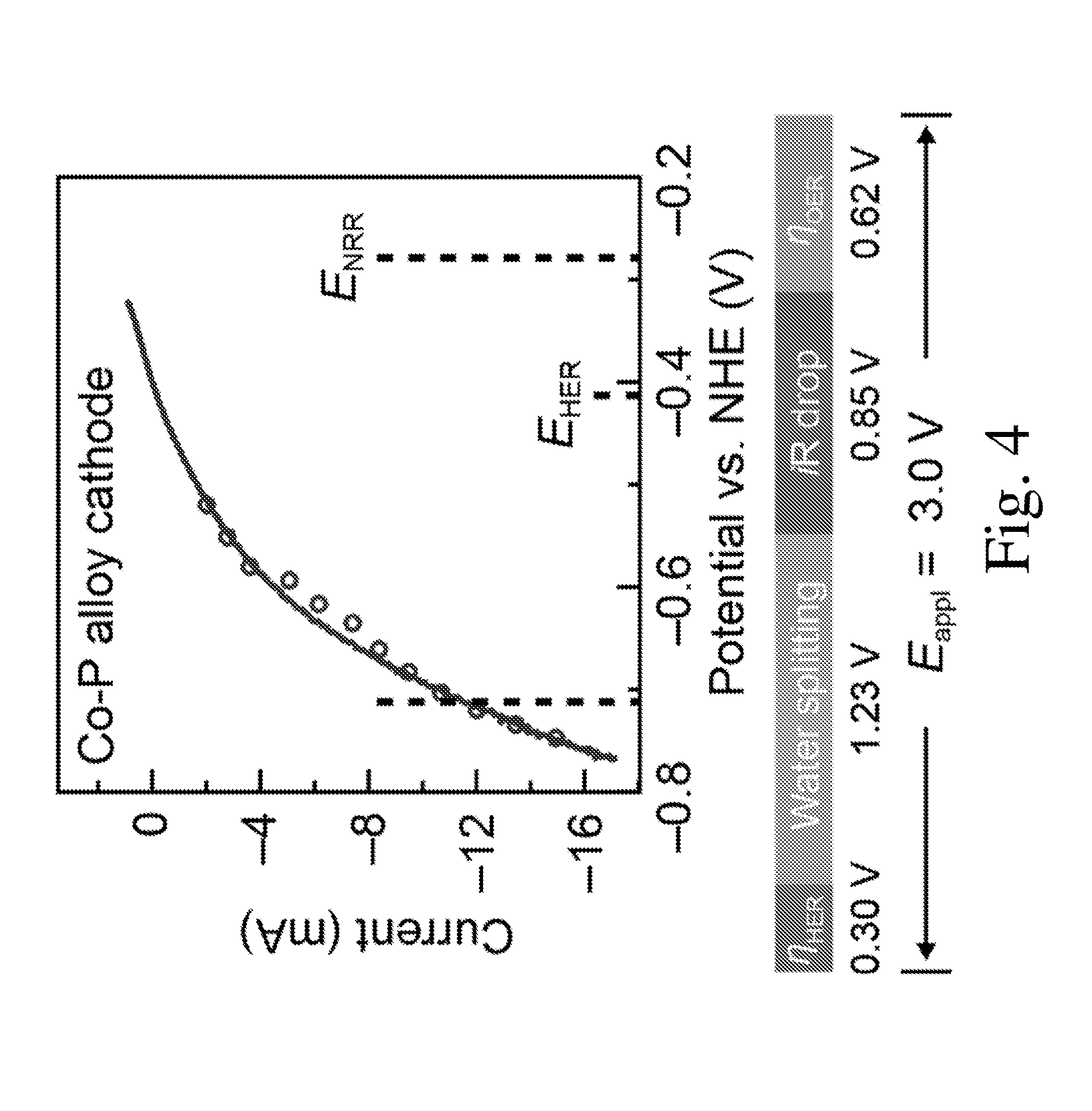
[0011] FIG. 4 is a graph of linear scan voltammetry (line, 10 mV/sec) and chronoamperometry (circle, 30 min average) of Co--P HER cathode in X. autotrophicus medium, iR corrected;
[0012] FIG. 5 Is a schematic diagram of NH.sub.3 production in an extracellular media; and
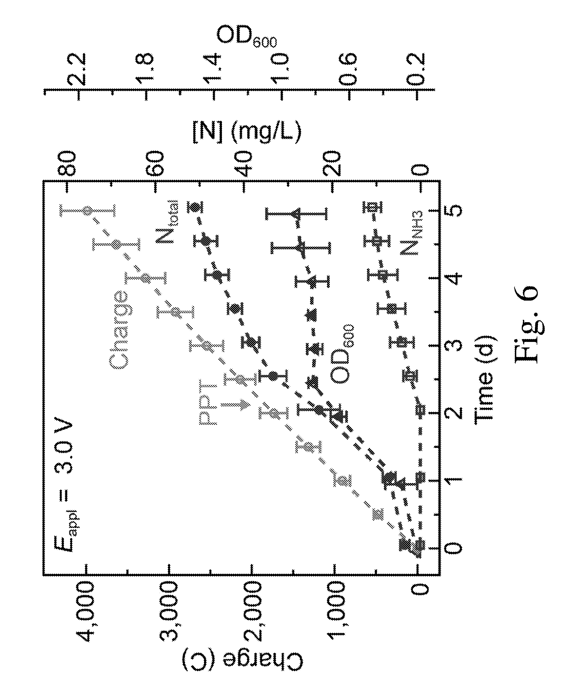
[0013] FIG. 6 is a graph of OD.sub.600, the amount of charge passed through, the concentration of total nitrogen content (N.sub.total) and NH.sub.3/NH.sub.4.sup.+ extracellular content (NH.sub.3) plotted against time.
DETAILED DESCRIPTION
[0014] Unlike more traditional production methods, catalytic NH.sub.3 synthesis from N.sub.2 has been reported with transition metal complexes, electrocatalysts, photocatalysts, nitrogenase, and heterotrophic diazotrophs. However, these approaches typically provide limited turnovers and use sacrificial chemicals as reductants. Consequently, the Inventors have recognized that it may be desirable to enable a selective NH.sub.3 synthesis from N.sub.2 and H.sub.2O at ambient conditions. This may help enable a distributed approach towards NH.sub.3 synthesis at ambient conditions, which may also be integrated with different forms of power including renewable energy sources. Possible benefits associated with such a production approach may include enabling on-site production and deployment of ammonia while also reducing CO.sub.2 emissions as compared to more traditional production methods.
[0015] In view of the above, the Inventors have recognized the benefits associated with using a reactor-based arrangement including a solution with one or more types of bacteria that include one or more enzymes useful in the production of ammonia. Specifically, in one embodiment, a system for producing ammonia may include a reactor with a chamber containing a solution. The solution may include dissolved hydrogen, carbon dioxide, and nitrogen as well as a glutamine synthetase inhibitor in the solution. The solution may also include one or more forms of autotrophic diazotroph bacteria in the solution. During use, the autotrophic diazotroph bacteria metabolize compounds within the solution to produce ammonia. Specifically, the bacteria may include nitrogenase, such as RuBisCO, and hydrogenase enzymes that utilize nitrogen, carbon dioxide, and hydrogenase to form the desired ammonia. Appropriate autotrophic diazotroph bacteria include Xanthobacter autotrophicus, Bradyrhizobium japonicum, or any other appropriate bacteria capable of metabolizing the noted compounds to produce ammonia.
[0016] Depending on the embodiment, an inhibitor may be included in a solution to at least partially prevent the uptake of ammonia into the biomass of the bacteria. Thus, at least a portion of the ammonia produced by the bacteria may be excreted into the solution for subsequent collection. In one specific embodiment a glutamine synthetase (GS) inhibator such as glufosinate (PPT), methionine sulfoximine (MSO), or any other appropriate inhibitor may be used.
[0017] In some embodiments, a solution placed in the chamber of a reactor may include water with one or more additional solvents, compounds, and/or additives. For example, the solution may include: inorganic salts such as phosphates including sodium phosphates and potassium phosphates; trace metal supplements such as iron, nickel, manganese, zinc, copper, and molybdenum; or any other appropriate component in addition to the dissolved gasses noted above. In one such embodiment, a phosphate may have a concentration between 9 and 50 mM.
[0018] The above noted concentrations of dissolved gases may be controlled in any number of ways including bubbling gases through the solution, generating the dissolved gases within the solution (e.g. electrolysis), or any other appropriate method of controlling the concentration of dissolved gas within the solution. Additionally, the various methods of controlling concentration may either be operated in a steady-state mode with constant operating parameters, and/or a concentration of one or more of the dissolved gases may be monitored to enable a feedback process to actively change the concentrations, generation rates, or other appropriate parameter to change the concentration of dissolved gases to be within the desired ranges noted above. Monitoring of the gas concentrations may be done in any appropriate manner including pH monitoring, dissolved oxygen meters, gas chromatography, or any other appropriate method.
[0019] In some embodiments, hydrogen may be provided to a solution using the electrolysis of water, i.e. water splitting. Depending on the particular embodiment, a power source may be connected to a first electrode and a second electrode that are at least partially immersed in a solution within a reactor chamber. The power source may correspond to any appropriate source of electrical current that is applied to the electrodes. However, in at least one embodiment, the power source may correspond to a renewable source of energy such as a solar cell, wind turbine, or any other appropriate source of current though embodiments in which a non-renewable energy source is used are also contemplated. In either case, a current from the power source is passed through the electrodes and solution to evolve hydrogen and oxygen. The current may be controlled to produce a desired amount of hydrogen and/or oxygen production at a desired rate of production. In one embodiment, the electrodes may be coated with, or formed from, a water splitting catalyst to further facilitate water splitting and/or reduce the voltage applied to the solution. For example, the electrodes may be made from one or more of a cobalt-phosphorus alloy, cobalt phosphate, cobalt oxide, cobalt hydroxide, cobalt oxyhydroxide, or any other appropriate material. In one specific embodiment, the first and second electrodes may correspond to a cathode including a cobalt-phosphorus alloy and an anode including cobalt phosphate. However, embodiments in which other types of anodes and/or cathodes are used are also contemplated as the disclosure is not so limited.
[0020] In instances where a phosphorus based anode and/or cathode is used, such as a cobalt-phosphorus alloy and/or a cobalt phosphate, a phosphate buffer may be included in the solution. Appropriate phosphates include, but are not limited to, sodium phosphates and potassium phosphates. Without wishing to be bound by theory, it is believed that during electrolysis of the water, phosphorus and/or cobalt is extracted from the electrodes. The reduction potential of leached cobalt is such that formation of cobalt phosphate from phosphate available in the solution is energetically favored. Cobalt phosphate formed in solution then deposits onto the anode at a rate linearly proportional to free cobalt phosphate, providing a self-healing process for the electrodes. A concentration of phosphate may be between 9 and 50 mM though other concentrations may also be used as the disclosure is not so limited.
[0021] In embodiments where hydrogen is produced using water electrolysis, a voltage applied to a pair of electrodes immersed in a solution may be limited to be between first and second voltage thresholds. In one such embodiment, the voltage applied to the electrodes may be greater than or equal to about 1.8 V, 2 V, 2.2 V, 2.4 V, or any other appropriate voltage. Additionally, the applied voltage may be less than or equal to about 3 V, 2.8 V, 2.6 V, 2.4 V, or any other appropriate voltage. Combinations of the above noted voltage ranges are contemplated including, for example, a voltage applied to a pair of electrodes that is between 1.8 V and 3 V. However, it should be understood that voltages both greater than and less than those noted above, as well as different combinations of the above ranges, are also contemplated as the disclosure is not so limited. For example, it is envisioned that other catalysts that enable a water splitting voltage closer to the ideal splitting voltage of 1.23 V may also be used.
[0022] As noted previously, in some embodiments, a flow of gas may be introduced to a solution contained within a reactor chamber to dissolve a desired ratio of gases in the solution. For example, in one embodiment, a system may include one or more gas sources that are fluidly connected to one or more gas inlets associated with the chamber. The gas inlets are arranged to bubble the gas through the solution. For example, a one-way valve may be fluidly connected to an inlet to the chamber bottom, a tube connected to a gas source may have an end immersed in the solution within the chamber, or the system may use any other appropriate arrangement to introduce the gases to the solution. Thus, when a gas source provides a pressurized flow of gas to the chamber, the gas is introduced into the solution where it bubbles up through the solution dissolving at least a portion of the gas therein.
[0023] While a gas source may correspond to any appropriate type of gas, in one embodiment, a gas source may provide one or more of hydrogen, nitrogen, carbon dioxide, and oxygen. Additionally, a total flow of gases provided by one or more gas sources to a solution within a reactor chamber may have any appropriate composition of gases. However, in one embodiment, a flow of gas may contain between 10 and 99.46% nitrogen, 0.04 and 90% carbon dioxide, and/or 0.5% and 5% oxygen. Of course embodiments in which a different mix of gases is bubbled through a solution including different gases and/or different concentrations both greater than and less than those noted above are also contemplated as the disclosure is not so limited.
EXAMPLES
[0024] A reactor used in the experiments included a biocompatible water splitting catalyst system including a cobalt-phosphorous (Co--P) alloy cathode for the hydrogen evolution reaction (HER) and a cobalt phosphate (CoP.sub.i) anode for the oxygen evolution reaction (OER). This system enabled the use of a low driving voltage (E.sub.appl) while producing the desired hydrogen for use in producing ammonia. Specifically, NH.sub.3 synthesis from N.sub.2 and H.sub.2O was accomplished using the water splitting system and driving the N.sub.2 reduction reaction within H.sub.2-oxidizing, autotrophic microorganisms. In this case, Xanthobacter autotrophicus (X. autotrophicus) was used. X. autotrophicus is a gram-negative bacterium that belongs to a small group of diazotrophs, which at micro-aerobic condition (less than about 5% O.sub.2) can use H.sub.2 as their sole energy source to fix CO.sub.2 and N.sub.2 into biomass. Therefore, in this experimental setup, electrochemical water splitting generated H.sub.2 as the biological energy source and in the same reactor X. autotrophicus acted as the room-temperature N.sub.2 reduction reaction catalyst to convert H.sub.2 and N.sub.2 into NH.sub.3.
[0025] FIG. 1 shows a schematic of the experimental setup including a single-chamber reactor that houses electrodes immersed in a water solution. The electrodes included a Co--P cathode for the hydrogen evolution reaction and a CoP.sub.i anode for the oxygen evolution reaction. A gas mixture including 2% O.sub.2, 20% CO.sub.2, and 78% N.sub.2 was bubbled through the solution at a flow rate of greater than or equal to 5 mL/min to maintain a micro-aerobic environment.
[0026] During the experiments, a constant voltage (E.sub.appl) was applied between the OER and HER electrodes for water splitting. The hydrogenases (H.sub.2ases) of X. autotrophicus oxidized the generated H.sub.2, fueling CO.sub.2 reduction in the Calvin cycle and N.sub.2 fixation by nitrogenases (N.sub.2ases). Each turnover of N.sub.2 reduction yields two NH.sub.3 and one H.sub.2 molecule(s), the latter of which may be recycled by the hydrogenases. The generated NH.sub.3 is typically incorporated into biomass, but can also diffuse extracellularly as a result of accumulation from inhibiting NH.sub.3 anabolism (pathway 2) as described previously.
[0027] At the beginning of each experiment, X. autotrophicus was inoculated into the organic-free minimal medium without any nitrogen supplement. A constant driving voltage (E.sub.appl=3.0 V) was applied to the CoP.sub.i|Co--P catalyst system, and aliquots were periodically sampled for the quantification of biomass (optical density at 600 nm, OD.sub.600) as well as fixed nitrogen (colorimetric assay).
[0028] The CoP.sub.i|Co--P| X. autotrophicus hybrid system used electricity to reduce N.sub.2, as well as CO.sub.2, into biomass without sacrificial reagents. FIG. 2 presents a graph of OD.sub.600, the amount of charge passed through, the concentration of total nitrogen content (N.sub.total), and soluble nitrogen content (N.sub.soluble) plotted versus the duration of the experiments. The OD.sub.600 in a H.sub.2-fermentation experiment ("H.sub.2 jar") was also plotted as a comparison. The error bars in the graph denote standard error of the mean (SEM) with n.gtoreq.3. As shown in the figure, the amount of charge passed into water splitting was proportional to biomass accumulation (OD.sub.600) as well as the total nitrogen content in the medium (N.sub.total) during the 5 day experiments.
[0029] FIG. 3 presents the change of N.sub.total and OD.sub.600 under different experimental conditions during the 5 day experiments. As seen in the figure, the fixed nitrogen was assimilated into biomass, as there was no change in the extracellular soluble nitrogen content (N.sub.soluble). 72.+-.5 mg/L of N.sub.total, as well as 553.+-.51 mg/L of dry cell weight, accumulated continuously over the experiment (n=3, entry 1 in FIG. 3). In contrast, no accumulation of N.sub.total was observed in controls that omitted one of the following elements in the design: water splitting, X. autotrophicus, a single-chamber reactor, and a microaerobic environment (entry 2 to 5 in FIG. 2b). Particularly in the case of the dual-chamber experiment (entry 4 in FIG. 3), the absence of N.sub.total accumulation is concurrent with the increase of soluble Co.sup.2+ concentration in the medium from 0.9.+-.0.2 .mu.M to 40.+-.6 .mu.M within 24 hours as determined by inductively coupled plasma mass spectroscopy (ICP-MS), which is close to the .about.50 .mu.M half maximum inhibitory concentration (IC.sub.50) of X. autotrophicus. Without wishing to be bound by theory, this may indicate that the installation of an anion exchange membrane (AEM) prevented the deposition of leached Co.sup.+ onto the CoP.sub.i anode, illustrating that the biocompatibility of the materials used in the system may be a desirable system property. As also illustrated in the figure, increases in OD.sub.600 that greatly exceed increases in N.sub.total (entry 4 and 5 in 3) are likely due to light scattering from the accumulation of poly(3-hydroxybutyrate), which is produced as a carbon storage polymer in conditions of nutrient constraints coupled with carbon excess.
[0030] The NRR activity of the described hybrid system is also supported by whole-cell acetylene reduction assays that were done. Specifically, aliquots were sampled directly from operating devices that were exposed to an O.sub.2/H.sub.2/CO.sub.2/Ar gas environment (2/10/10/78) and were able to reduce injected C.sub.2H.sub.2 exclusively into C.sub.2H.sub.4 at a rate of 127.+-.33 .mu.Mh.sup.-1OD.sub.600.sup.-1 (n=3). If the kinetic rate of C.sub.2H.sub.2 reduction by nitrogenase is one fourth of N.sub.2 reduction based on the reaction stoichiometry, this activity corresponds to .about.12 mg/L N.sub.total per day for cultures of OD.sub.600=1.0. This N.sub.2-fixing rate is consistent with the measured N.sub.total accumulation during the 5 day experiments and excludes the possibilities of other hypothetical nitrogen sources in conjunction with other controls (vide supra). This measurement corresponds to a NRR turnover frequency (TOF) of 1.4.times.10.sup.4 s.sup.-1 per bacterial cell. If assuming a nitrogenase copy number of about 5000 based on previous literature, this NRR TOF corresponds to roughly .about.3 s.sup.-1 per enzyme, which is consistent with previous studies. The equivalent turnover number (TON) is roughly 8.times.10.sup.9 per bacterial cell and 1.times.10.sup.6 per nitrogenase, at least 2 orders of magnitude higher than previously reported synthetic and biological catalysts.
[0031] FIG. 4 presents the results from linear scan voltammetry (line, 10 mV/sec) and chronoamperometry (circle, 30 min average) of Co--P HER cathode in X. autotrophicus medium, iR corrected. The thermodynamic values of HER and NRR (E.sub.HER, E.sub.NRR) are displayed. Voltage contributions from the applied E.sub.appl=3.0 V is shown below the I-V characterization. The NRR reaction operates with kinetic driving forces as low as 160 mV. The I-V characteristics of the Co--P HER cathode in X. autotrophicus medium indicate an apparent overpotential of about 0.43 V. Without wishing to be bound by theory, much of this value is not intrinsic to the catalytic properties of the electrodes, but originates from the build-up of a proton concentration gradient in the weakly buffered solution (9.4 mM phosphate). By subtracting the contribution of mass transport, the intrinsic NRR overpotential is about 0.16 V, much lower than previous reports in literature. The dilute medium salinity subsequently uses a driving voltage of E.sub.appl=3.0 V, which is higher than previous reported. The low ionic conductivity contributes to about 28% of E.sub.appl(.about.0.85 V), which may likely be reduced by additional optimization. Regardless, the energy efficiency of NRR (.eta..sub.elec,NRR) in the experiments is 1.8.+-.0.3% (n=3) during the 5 day experiments, in addition to the 11.6.+-.1.9% electrical CO.sub.2 reduction efficiency (.eta..sub.elec,CO2, n=3). This corresponds to .about.900 GJ per tonne NH.sub.3, while the thermodynamic limit is 20.9 GJ per tonne NH.sub.3. Based on the reaction stoichiometry of nitrogenase and upstream biochemical pathways, the theoretical number of H.sub.2 molecules needed to reduce one N.sub.2 molecule ranges in between 9.4.about.14.7, which sets an upper bound of .eta..sub.elec,NRR at 7.5.about.11.7%. Therefore, the amount of nitrogen reduction reported in this experiment is 15.about.23% of the theoretical yield, much higher than the faradaic efficiencies or quantum yields of other systems at ambient conditions.
[0032] The described experiments and systems exhibited faster N.sub.2 reduction and microbial growth as compared to gas fermentation at similar conditions. In contrast to the observed linear growth in the hybrid system (FIG. 2), gas fermentation in the same conditions supplemented with a headspace containing .about.10% H.sub.2 ("H.sub.2 jar" experiment in FIG. 2) shows relatively slow, nonlinear growth. This difference is dependent on N.sub.2 fixation, as growth under gas fermentation and electrolysis demonstrated no discernable difference when ammonia is supplemented into the medium. Without wishing to be bound by theory, it is believed that this is the result of competitive inhibition of H.sub.2 on nitrogenase, with an inhibition constant K.sub.is(D.sub.2) of .about.11 kPa. Where electrolysis maintains a low H.sub.2 partial pressure at steady state in the hybrid device, the high H.sub.2 concentration in gas fermentation may slow down the N.sub.2 fixation rate and/or reduce the NRR energy efficiency. This hypothesis is supported by numerical simulations, which show slower biomass accumulation in the case of gas fermentation. Therefore, the current experiments indicate that the described hybrid device can provide additional benefits as compared to the simple combination of gas fermenters with a water-splitting electrolyzer, as the generated H.sub.2 from water splitting can influence downstream biochemical pathways.
[0033] The hybrid device is capable of excreting synthesized NH.sub.3 into an extracellular medium. Previous biochemical assays and genome sequencing on this strain indicate that the NH.sub.3 generated from nitrogenase is incorporated into biomass via a two-step process mediated by glutamine synthetase (GS) and glutamate synthase (GOGAT) (FIGS. 1 and 5). If the functionality of this NH.sub.3 assimilation pathway is disrupted, direct production of an extracellular NH.sub.3 fertilizer solution is realized. It has been reported that GS inhibitors can be used for NH.sub.3 secretion in sugar-fementating diazotrophs. As a proof of principle, glufosinate (PPT), a specific GS inhibitor commercially used as herbicide, was used to block the NH.sub.3 assimilation pathway and allow the synthesized NH.sub.3 to passively diffuse out into the extracellular medium (pathway 2 in FIG. 1, and FIG. 5). After the addition of PPT, the biomass of X. autotrophicus stagnated, while N.sub.tw and the concentration of free NH.sub.3 in the solution (N.sub.NH3) increased (FIG. 6). This indicates that nitrogen accumulation after PPT addition mostly took the form of extracellular NH.sub.3. In the end of experiments, the concentration of N.sub.NH3 was 11.+-.2 mg/L (.about.0.8 mM) and the accumulated N.sub.total reached 47.+-.3 mg/L (n=3, Table S1). The rate of N.sub.2 fixation tends to slow down in the latter phase of the experiments, which may be related to nitrogen regulation at transcriptional and post-transcriptional levels. Further engineering in synthetic biology is capable of alleviating this limitation.
[0034] The above experiments demonstrate the production and use of an alternative NH.sub.3 synthesis approach from N.sub.2, H.sub.2O, and electricity. The water splitting-biosynthetic process operates at ambient conditions and can be distributed for an on-demand supply of nitrogen fertilizer. When coupled with a renewable energy supply such as a photovoltaic device of 18% energy efficiency, solar-powered N.sub.2 fixation into NH.sub.3 can be achieved at up to a 0.3% solar-to-NH.sub.3 efficiency along with a 2.1% solar CO.sub.2 reduction efficiency. A typical cropping system annually reduces .about.11 g nitrogen per m.sup.2, which corresponds to a .about.4.times.10.sup.5 solar-to-NH.sub.3 efficiency (assuming 2000 kWh/m.sup.2 annual solar irradiance). Therefore, this approach yields a much higher efficiency and provides a sustainable route for fertilizer production without the use of fossil fuels. Though instances in which the various feeds stocks (i.e. gases) could be provided using fossil fuels as the current disclosure is not limited to only using renewable energies and/or splitting water directly in a reactor to produce the desire ammonia generation.
[0035] While the present teachings have been described in conjunction with various embodiments and examples, it is not intended that the present teachings be limited to such embodiments or examples. On the contrary, the present teachings encompass various alternatives, modifications, and equivalents, as will be appreciated by those of skill in the art. Accordingly, the foregoing description and drawings are by way of example only.
* * * * *
D00000
D00001
D00002
D00003
D00004
D00005
D00006
XML
uspto.report is an independent third-party trademark research tool that is not affiliated, endorsed, or sponsored by the United States Patent and Trademark Office (USPTO) or any other governmental organization. The information provided by uspto.report is based on publicly available data at the time of writing and is intended for informational purposes only.
While we strive to provide accurate and up-to-date information, we do not guarantee the accuracy, completeness, reliability, or suitability of the information displayed on this site. The use of this site is at your own risk. Any reliance you place on such information is therefore strictly at your own risk.
All official trademark data, including owner information, should be verified by visiting the official USPTO website at www.uspto.gov. This site is not intended to replace professional legal advice and should not be used as a substitute for consulting with a legal professional who is knowledgeable about trademark law.