Composite Pallet
WANG; Yunping ; et al.
U.S. patent application number 15/909655 was filed with the patent office on 2019-07-04 for composite pallet. The applicant listed for this patent is HUIZHOU CHINA STAR OPTOELECTRONICS TECHNOLOGY CO., LTD.. Invention is credited to Yuchun HSIAO, Yunping WANG, Gang YU.
| Application Number | 20190202597 15/909655 |
| Document ID | / |
| Family ID | 67059346 |
| Filed Date | 2019-07-04 |
| United States Patent Application | 20190202597 |
| Kind Code | A1 |
| WANG; Yunping ; et al. | July 4, 2019 |
COMPOSITE PALLET
Abstract
The present disclosure discloses a composite pallet includes a support plate, a support frame and a plurality of support legs, wherein the support plate is detachably disposed on the support frame, the support legs are detachably disposed on the surface of the support frame facing away from the support plate, and the plurality of support legs are spaced apart from each other. The composite pallet disclosed in the present disclosure has a simple structure and a low cost by assembling a support plate, a support frame and a support leg detachably to form a composite pallet, and the pallet has strong supporting strength, at the same time the pallet of the various components can be disassembled, improve the recycling of various components.
| Inventors: | WANG; Yunping; (Huizhou Guangdong, CN) ; YU; Gang; (Huizhou Guangdong, CN) ; HSIAO; Yuchun; (Huizhou Guangdong, CN) | ||||||||||
| Applicant: |
|
||||||||||
|---|---|---|---|---|---|---|---|---|---|---|---|
| Family ID: | 67059346 | ||||||||||
| Appl. No.: | 15/909655 | ||||||||||
| Filed: | March 1, 2018 |
Related U.S. Patent Documents
| Application Number | Filing Date | Patent Number | ||
|---|---|---|---|---|
| PCT/CN2018/074372 | Jan 27, 2018 | |||
| 15909655 | ||||
| Current U.S. Class: | 1/1 |
| Current CPC Class: | B65D 2519/00069 20130101; B65D 2519/00139 20130101; B65D 2519/00437 20130101; B65D 2519/00567 20130101; B65D 2519/00338 20130101; B65D 2519/00029 20130101; B65D 2519/00064 20130101; B65D 2519/00288 20130101; B65D 2519/00293 20130101; B65D 2519/00273 20130101; B65D 2519/00572 20130101; B65D 2519/00024 20130101; B65D 2519/00034 20130101; Y02W 30/80 20150501; B65D 19/0028 20130101; B65D 2519/00059 20130101; B65D 2519/00134 20130101; B65D 2519/00373 20130101; B65D 2519/00129 20130101; B65D 2519/00323 20130101; B65D 19/0075 20130101 |
| International Class: | B65D 19/00 20060101 B65D019/00 |
Foreign Application Data
| Date | Code | Application Number |
|---|---|---|
| Jan 3, 2018 | CN | 201810005672.X |
Claims
1. A composite pallet, comprising a support plate, a support frame and a plurality of support legs, wherein the support plate is detachably disposed on the support frame, the support legs are detachably disposed on a surface of the support frame facing away from the support plate, and the plurality of support legs are spaced apart from each other.
2. The composite pallet according to claim 1, wherein the support frame comprises four bezels connected end to end vertically, a number of the support legs is four, and the four support legs are respectively fixed on four corners of the support frame.
3. The composite pallet according to claim 2, wherein a surface portion of the support leg facing the support frame is partially recessed to form a first groove and a second groove, the first groove and the second groove are perpendicular to each other and connected to each other, and two bezels connecting to the same corner respectively engage with the first groove and the second groove.
4. The composite pallet according to claim 3, wherein the support frame further comprises a first reinforcement strip and a second reinforcement strip cross-connected to each other, two ends of the first reinforcement strip are respectively connected to two corners on one diagonal of the support frame, two ends of the second reinforcing strip are respectively connected to two corners on the other diagonal of the support frame.
5. The composite pallet according to claim 4, wherein the composite pallet further comprises a first auxiliary leg, the first auxiliary leg is fixed on a surface facing away from the support plate at the intersection of the first reinforcing strip and the second reinforcing strip.
6. The composite pallet according to claim 5, wherein a surface of the first auxiliary leg facing the support plate is provided with a third groove and a fourth groove crossing each other and connected to each other, the first reinforcing strip engages with the third groove, and the second reinforcing strip engages with the fourth groove.
7. The composite pallet according to claim 4, wherein the support frame further comprises four third reinforcing strips connected end to end vertically and two ends of each third reinforcing strip are respectively connected to the two adjacent bezels.
8. The composite pallet according to claim 7, wherein the composite pallet further comprises four second auxiliary legs which are fixed on a surface of a connecting portion between the third reinforcing strip and the bezel and facing away from the support plate.
9. The composite pallet according to claim 7, wherein a portion of a surface of the second auxiliary leg facing the support plate is partially recessed to form a fifth groove and a sixth groove connected to each other, the bezel is engaged in the fifth groove, and the third reinforcing strip is engaged in the sixth groove.
10. The composite pallet according to claim 1, wherein the composite pallet further comprises a first locking member and a second locking member, a first locking hole is further disposed on the support frame, the first locking member is inserted through the first locking hole and the first locking member locks the support frame on the support leg; a second locking hole is formed on the support plate, the second locking member is inserted through the second locking hole, and the second locking member locks the support plate to the support frame.
11. The composite pallet according to claim 10, wherein the support frame comprises four bezels connected end to end vertically, a number of the support legs is four, and the four support legs are respectively fixed on four corners of the support frame.
12. The composite pallet according to claim 11, wherein a surface portion of the support leg facing the support frame is partially recessed to form a first groove and a second groove, the first groove and the second groove are perpendicular to each other and connected to each other, and two bezels connecting to the same corner respectively engage with the first groove and the second groove.
13. The composite pallet according to claim 12, wherein the support frame further comprises a first reinforcement strip and a second reinforcement strip cross-connected to each other, two ends of the first reinforcement strip are respectively connected to two corners on one diagonal of the support frame, two ends of the second reinforcing strip are respectively connected to two corners on the other diagonal of the support frame.
14. The composite pallet according to claim 13, wherein the composite pallet further comprises a first auxiliary leg, the first auxiliary leg is fixed on a surface facing away from the support plate at the intersection of the first reinforcing strip and the second reinforcing strip.
15. The composite pallet according to claim 14, wherein a surface of the first auxiliary leg facing the support plate is provided with a third groove and a fourth groove crossing each other and connected to each other, the first reinforcing strip engages with the third groove, and the second reinforcing strip engages with the fourth groove.
Description
RELATED APPLICATIONS
[0001] The present application is a National Phase of International Application Number PCT/CN2018/074372, filed Jan. 27, 2018, and claims the priority of China Application 201810005672.X, filed Jan. 3, 2018.
FIELD OF THE DISCLOSURE
[0002] The present disclosure relates to a display technology field, and more particularly to a composite pallet.
BACKGROUND OF THE DISCLOSURE
[0003] The pallet is a plurality of liquid crystal panel packaging boxes commonly used in the technical field of packaging of liquid crystal panels for carrying stacks to facilitate the transportation of the liquid crystal panels. In the prior art, the plastic pallets are more common, wherein the plastic pallets are integrally injection-molded, so that all parts of the plastic pallets such as squats, panels and stiffeners are one connection, not removable. When one of the parts is damaged, the entire plastic pallet can not be used, resulting in a great waste, but also can not be recycled parts of which intact structure, recycling rate at the end. On the other hand, one of the high cost of injection molding, is not conducive to mass production.
SUMMARY OF THE DISCLOSURE
[0004] The technical problem to be solved by the present disclosure is to overcome the deficiencies of the prior art and to provide a composite pallet with low cost and detachable components.
[0005] In order to achieve the above object, the present disclosure adopts the following technical solutions.
[0006] A composite pallet includes a support plate, a support frame and a plurality of support legs, wherein the support plate is detachably disposed on the support frame, the support legs are detachably disposed on the surface of the support frame facing away from the support plate, and the plurality of support legs are spaced apart from each other.
[0007] Optionally, the support frame includes four bezels connected end to end vertically, the number of the support legs is four, and the four support legs are respectively fixed on four corners of the support frame.
[0008] Optionally, the surface portion of the support leg facing the support frame is partially recessed to form a first groove and a second groove, the first groove and the second groove are perpendicular to each other and connected to each other, and two bezels connected to the same corner respectively engage with the first groove and the second groove.
[0009] Optionally, the support frame further includes a first reinforcement strip and a second reinforcement strip cross-connected to each other, two ends of the first reinforcement strip are respectively connected to two corners on one diagonal of the support frame, two ends of the second reinforcing strip are respectively connected to two corners on the other diagonal of the support frame.
[0010] Optionally, the composite pallet further includes a first auxiliary leg, the first auxiliary leg is fixed on the surface facing away from the support plate at the intersection of the first reinforcing strip and the second reinforcing strip.
[0011] Optionally, the surface of the first auxiliary leg facing the support plate is provided with a third groove and a fourth groove crossing each other and connected to each other, the first reinforcing strip engages with the third groove, and the second reinforcing strip engages with the fourth groove.
[0012] Optionally, the support frame further includes four third reinforcing strips connected end to end vertically and two ends of each third reinforcing strip are respectively connected to the two adjacent bezels.
[0013] Optionally, the composite pallet further includes four second auxiliary legs which are fixed on the surface of the connecting portion between the third reinforcing strip and the bezel and facing away from the support plate.
[0014] Optionally, the portion of the surface of the second auxiliary leg facing the support plate is partially recessed to form a fifth groove and a sixth groove connected to each other, the bezel is engaged in the fifth groove, and the third reinforcing strip is engaged in the sixth groove.
[0015] Optionally, the composite pallet further includes a first locking member and a second locking member, a first locking hole is further disposed on the support frame, the first locking member is inserted through the first locking hole and the first locking member locks the support frame on the support leg; a second locking hole is formed on the support plate, the second locking member is inserted through the second locking hole, and the second locking member locks the support plate to the support frame.
[0016] According to the composite pallet disclosed in the present disclosure, a composite pallet is formed by assembling a support plate, a support frame and a support leg detachably. The structure of the pallet is simple, the cost is low, and the pallet has stronger supporting strength, meanwhile, the various components of the pallet can be disassembled, which improves the recycling rate of each component.
BRIEF DESCRIPTION OF THE DRAWINGS
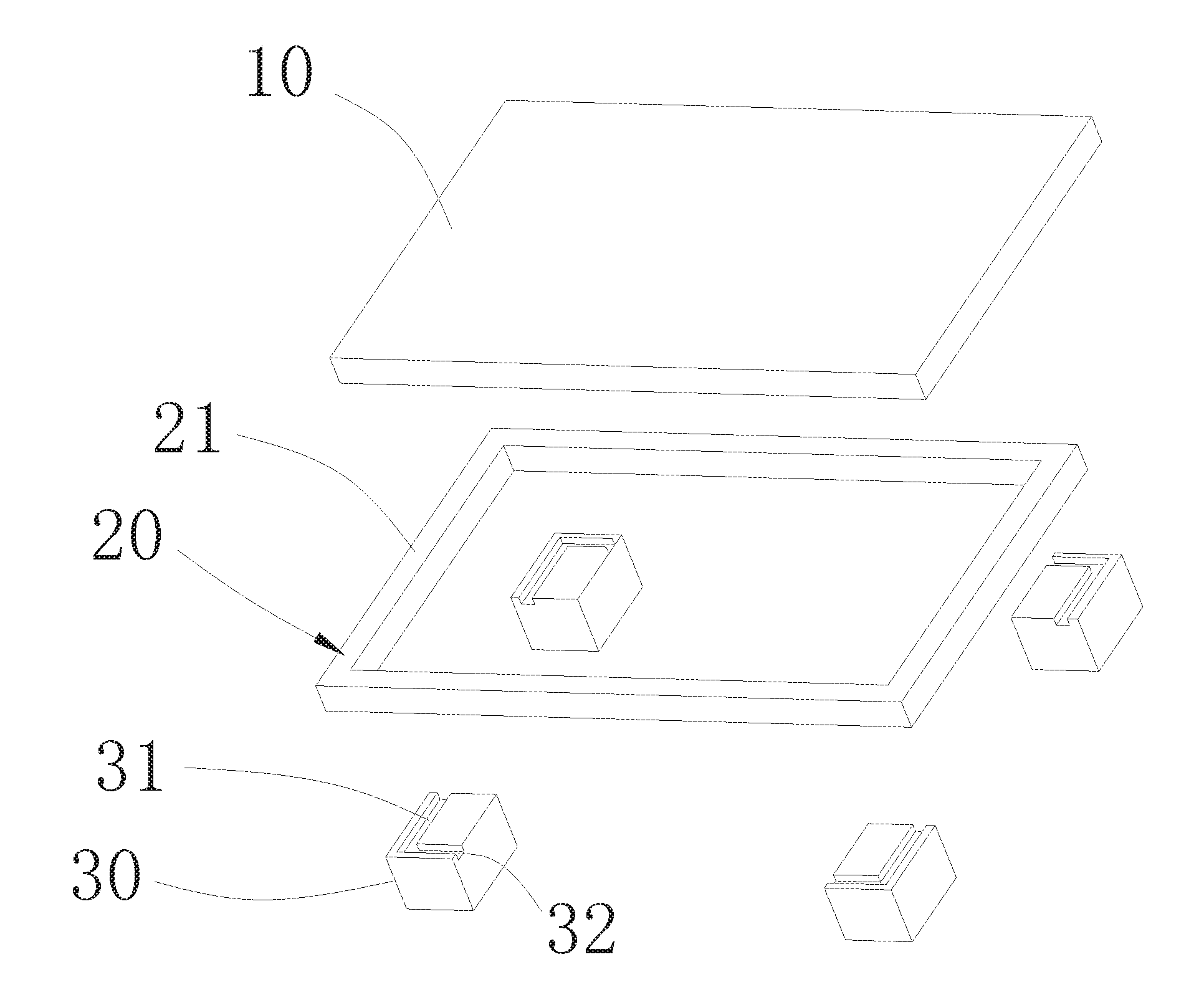
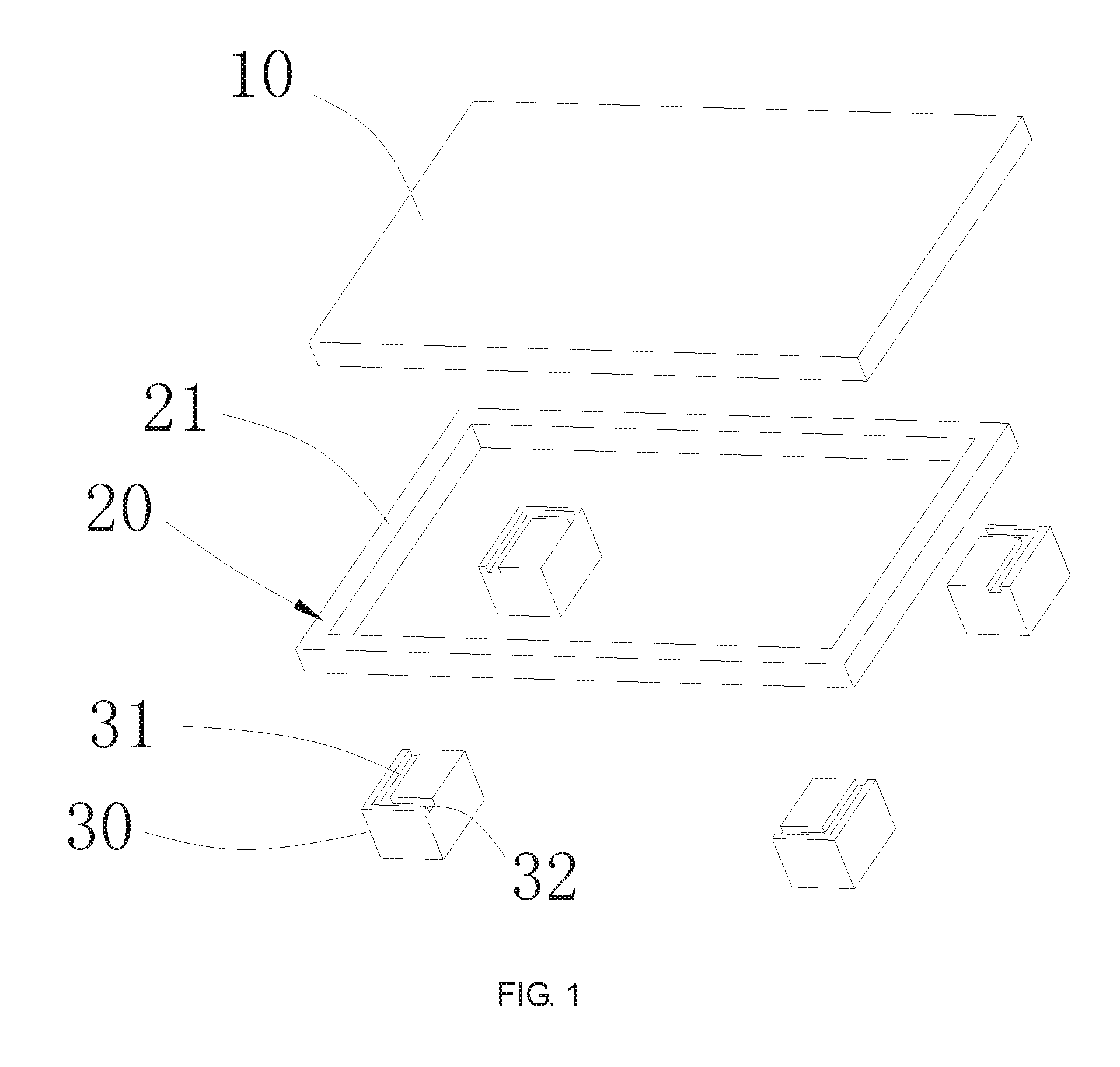
[0017] FIG. 1 is an exploded diagram of a composite pallet according to the embodiment of the present disclosure.
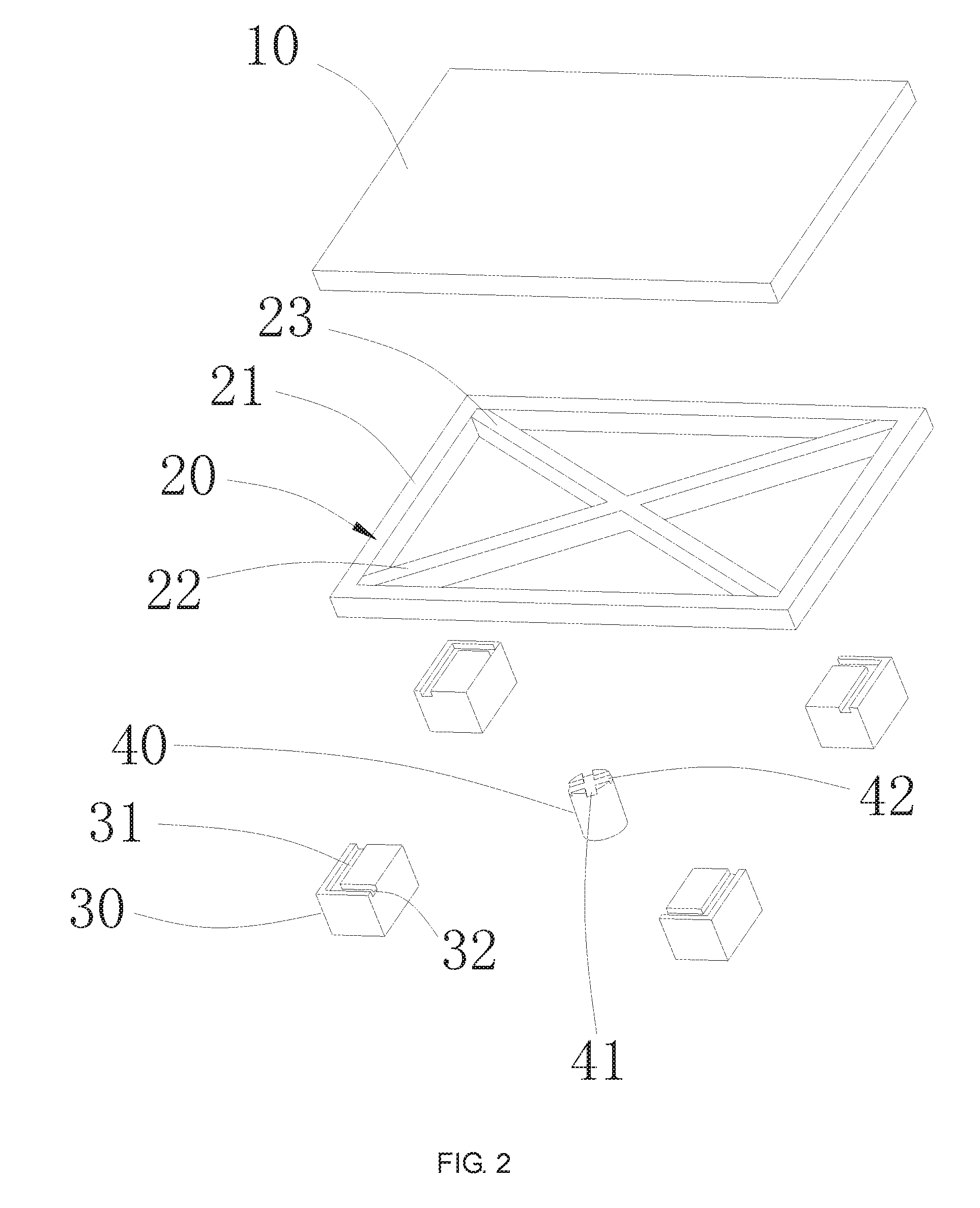
[0018] FIG. 2 is an exploded diagram of another structure of the composite pallet according to the embodiment of the present disclosure.
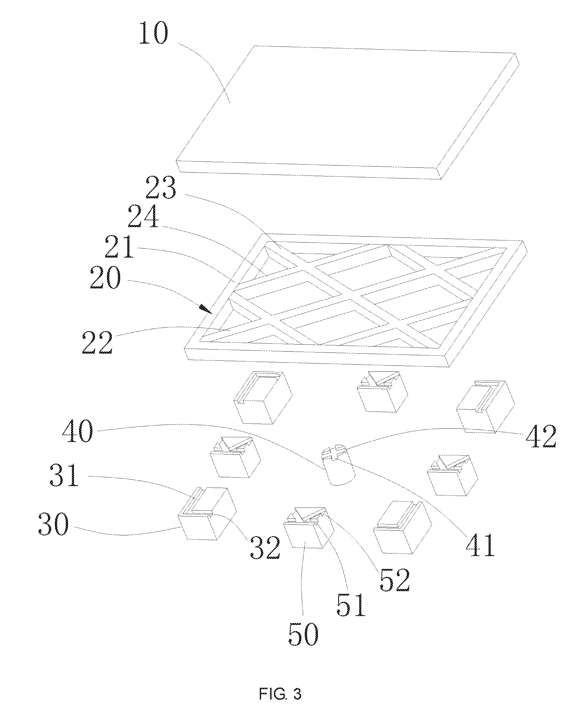
[0019] FIG. 3 is an exploded diagram of the other structure of the composite pallet according to the embodiment of the present disclosure.
DETAILED DESCRIPTION OF PREFERRED EMBODIMENTS
[0020] In order to make the objectives, technical solutions and advantages of the present disclosure more comprehensible, the present disclosure is further described in detail below with reference to the accompanying drawings and embodiments. It should be understood that the specific embodiments described herein are merely used to explain the present disclosure, and are not intended to limit the present disclosure.
[0021] Referring to FIG. 1, a composite pallet of the present embodiment includes a support plate 10, a support frame 20 and a plurality of support legs 30, wherein the support plate 10 is detachably disposed on the support frame 20, the support legs 30 are detachably disposed on the surface of the support frame 20 facing away from the support plate 10, and the plurality of support legs 30 are spaced apart from each other. As a preferred embodiment, the composite pallet further includes a first locking member and a second locking member, a first locking hole is further disposed on the support frame 20, the first locking member is inserted through the first locking hole and the first locking member locks the support frame 20 on the support leg 30; a second locking hole is formed on the support plate 10, the second locking member is inserted through the second locking hole, and the second locking member locks the support plate 10 to the support frame 20. a support plate 10, a support frame 20 and a plurality of support legs 30 are formed together to form a composite pallet.
[0022] As a preferred embodiment, the support frame 20 is a rectangular frame, and the support frame 20 includes four bezels 21 connected end to end vertically. The number of the support legs 30 is four, and the four support legs 30 are respectively fixed on the four corners of the support frame 20, so that the support frame 20 is uniformly stressed and has good stability. The shape of the support leg 30 is cylindrical or cuboid.
[0023] Further, the surface portion of the support leg 30 facing the support frame 20 is partially recessed to form a first groove 31 and a second groove 32, the first groove 31 and the second groove 32 are perpendicular and connected to each other. The two bezels 21 connecting to the same corner are respectively fixed in the first groove 31 and the second groove 32. With the use of the disposing groove, the support frame 20 can be more stably connected to the support legs 30 to prevent the support frame 20 from being displaced from the support legs 30, meanwhile, the support frame 20 partially overlaps with the support leg 30 in the height direction, reducing the overall height of the composite pallet.
[0024] As a preferred embodiment, as shown in FIG. 2, the support frame 20 further includes a first reinforcing strip 22 and a second reinforcing strip 23 that are cross-connected to each other, two ends of the first reinforcing strip 22 are respectively connected to two corners on one diagonal of the support frame 20, two ends of the second reinforcing strip 23 are respectively connected to the two corners on the other diagonal of the support frame 20. That is, the first reinforcing strip 22 and the second reinforcing strip 23 form an X-shaped structure, which enhances the overall supporting strength of the support frame 20.
[0025] Further, the composite pallet further includes a first auxiliary leg 40. The first auxiliary leg 40 is fixed on the surface of the composite pallet facing away from the support plate 10 at the intersection of the first reinforcement strip 22 and the second reinforcement strip 23. In this way, the supporting force received by the support frame 20 is more uniform, thereby improving the stability of the composite pallet. Further, the first auxiliary leg 40 is preferably fastened at the intersection of the first reinforcement strip 22 and the second reinforcement strip 23 by screwing. The shape of the first auxiliary leg 40 is cylindrical or cuboid.
[0026] Further, the surface of the first auxiliary leg 40 facing the support plate 10 is provided with a third groove 41 and a fourth groove 42 intersecting and connected to each other. The central portion of the first reinforcing strip 22 is engaged with the third groove 41, the central portion of the second reinforcing strip 23 is engaged with the fourth groove 42. The connection between the first reinforcing strip 22 and the first reinforcing strip 22 and the first auxiliary leg 40 is further stabilized and the first auxiliary leg 40 is easily detached from the first reinforcing strip 22 and the first reinforcing strip 22, which is beneficial to the recycling of the first auxiliary leg 40. It should be noted that the end face of the first auxiliary leg 40 facing away from the support plate 10 is flush with the end face of the support leg 30 facing away from the support plate 10, so as to ensure the stability of the composite pallet.
[0027] As a preferred embodiment, as shown in FIG. 3, the support frame 20 further includes four third reinforcing strips 24 connected end to end vertically and each end of each third reinforcing strip 24 is respectively connected to two adjacent bezels 11. The four third reinforcing strips 24 form a square structure, which enhances the overall supporting strength of the support frame 20, at the same time, the frame 21, the first reinforcing strip 22, the second reinforcing strip 23 and the third reinforcing strip 24 divide the support frame 20 into a plurality of small supporting areas. In this way, the supporting force received by the support plate 10 is more uniform, which enhances the overall supporting strength of the composite pallet.
[0028] Further, the composite pallet further includes four second auxiliary legs 50. The second auxiliary legs 50 are fixed on the surface of the connection portion between the third reinforcement strip 24 and the bezel 11 and facing away from the support plate 10. In this way, the supporting force received by the support frame 20 is more uniform, thereby improving the stability of the composite pallet.
[0029] Further, the surface of the second auxiliary leg 50 facing the support plate 10 is partially recessed to form a fifth groove 51 and a sixth groove 52 connected to each other, the frame 11 is partially engaged in the fifth groove 51, and the third reinforcing strip 24 is engaged in the sixth groove 52. The connection between the frame 11 and the third reinforcement bar 24 and the second auxiliary leg 50 is further stabilized, at the same time, the second auxiliary leg 50 is conveniently detached from the first reinforcing strip 22 and the first reinforcing strip 22, which facilitates the recycling of the second auxiliary leg 50. It should be noted that the end face of the second auxiliary leg 50 facing away from the support plate 10 is flush with the end face of the support leg 30 facing away from the support plate 10, so as to ensure the stability of the composite pallet. Further, the second auxiliary leg 50 is preferably fastened at the connection between the frame 11 and the third reinforcement bar 24 by screwing. The shape of the second auxiliary leg 50 is a cylinder shape or a square shape.
[0030] The material of the support frame 20 in this embodiment may be a metal material, a plastic material, a wood material, a composite material, or the like. The shapes of the respective bezels and the reinforcing strips of the support frame 20 may be tubular or strip-shaped. The material of the support leg 30, the first auxiliary leg 40 and the second auxiliary leg 50 may be metal material, plastic material, wood material or composite material.
[0031] The support plate 20 and the support frame 20 of the present embodiment can also be combined together by structural engagement.
[0032] The composite pallet disclosed in the present disclosure has a simple structure and a low cost by assembling a support plate, a support frame and a support leg detachably to form a composite pallet, and the pallet has strong supporting strength, at the same time the pallet of the various components can be disassembled, improve the recycling of various components.
[0033] While specific embodiments of the present disclosure have been described in detail, some embodiments have been shown and described. It will be understood by those skilled in the art that these embodiments may be modified and improved without departing from the spirit and scope of the present disclosure as defined by the claims and their equivalents, and such modifications and improvements should also fall within the protection scope of the present disclosure.
* * * * *
D00000
D00001
D00002
D00003
XML
uspto.report is an independent third-party trademark research tool that is not affiliated, endorsed, or sponsored by the United States Patent and Trademark Office (USPTO) or any other governmental organization. The information provided by uspto.report is based on publicly available data at the time of writing and is intended for informational purposes only.
While we strive to provide accurate and up-to-date information, we do not guarantee the accuracy, completeness, reliability, or suitability of the information displayed on this site. The use of this site is at your own risk. Any reliance you place on such information is therefore strictly at your own risk.
All official trademark data, including owner information, should be verified by visiting the official USPTO website at www.uspto.gov. This site is not intended to replace professional legal advice and should not be used as a substitute for consulting with a legal professional who is knowledgeable about trademark law.