Carrier For Robot And Robot Having The Same
Chen; Sheng-Chia ; et al.
U.S. patent application number 15/857474 was filed with the patent office on 2019-07-04 for carrier for robot and robot having the same. The applicant listed for this patent is AEOLUS ROBOTICS CORPORATION LIMITED. Invention is credited to Sheng-Chia Chen, Chia-Chun Li, Sheng-Chih Lin.
| Application Number | 20190202052 15/857474 |
| Document ID | / |
| Family ID | 64755131 |
| Filed Date | 2019-07-04 |


View All Diagrams
| United States Patent Application | 20190202052 |
| Kind Code | A1 |
| Chen; Sheng-Chia ; et al. | July 4, 2019 |
CARRIER FOR ROBOT AND ROBOT HAVING THE SAME
Abstract
The present disclosure relates to a robot, comprising: a movable base; and a torso arranged on the base. The torso comprises a first portion mounted to the base; a second portion installed to the first portion, wherein the second portion could be moved relative to the first portion; and a support substantially connected to the second portion.
| Inventors: | Chen; Sheng-Chia; (Taipei, TW) ; Lin; Sheng-Chih; (Taipei, TW) ; Li; Chia-Chun; (Taipei, TW) | ||||||||||
| Applicant: |
|
||||||||||
|---|---|---|---|---|---|---|---|---|---|---|---|
| Family ID: | 64755131 | ||||||||||
| Appl. No.: | 15/857474 | ||||||||||
| Filed: | December 28, 2017 |
| Current U.S. Class: | 1/1 |
| Current CPC Class: | B25J 9/0009 20130101; B25J 11/008 20130101; B25J 9/1697 20130101; B25J 5/007 20130101; B25J 9/1684 20130101; B25J 19/021 20130101; G05B 2219/40298 20130101; B25J 19/0029 20130101; B25J 9/162 20130101 |
| International Class: | B25J 9/16 20060101 B25J009/16; B25J 5/00 20060101 B25J005/00; B25J 9/00 20060101 B25J009/00; B25J 19/00 20060101 B25J019/00; B25J 19/02 20060101 B25J019/02 |
Claims
1. A robot, comprising: a movable base; and a torso arranged on the base, the torso comprising: a first portion mounted to the base; a second portion installed to the first portion, wherein the second portion could be moved relative to the first portion; and a support substantially connected to the second portion.
2. The robot of claim 1, wherein the support is substantially arranged at the front of the torso.
3. The robot of claim 2, wherein the support has a joint such that the support is foldable.
4. The robot of claim 3, further comprising a robotic arm connected to the second portion of the torso, wherein the robotic arm has at least one degree of freedom with respect to the second portion of the torso.
5. The robot of claim 4, wherein the robotic arm comprises a first unit and a second unit, wherein one end of the first unit is connected to the second portion of the torso and the second unit is connected to the other end of the first unit, and wherein the first unit has at least one degree of freedom with respect to the second portion of the torso and the second unit has at least one degree of freedom with respect to the first unit.
6. The robot of claim 1, wherein the support is disposed at one side of the torso.
7. The robot of claim 6, further comprising a robotic arm connected to the other side of the torso, wherein the robotic arm has at least one degree of freedom with respect to the torso.
8. The robot of claim 7, wherein the robotic arm comprises a first unit and a second unit, wherein one end of the first unit is connected to the torso and the second unit is connected to the other end of the first arm unit, and wherein the first unit has at least one degree of freedom with respect to the torso and the second unit has at least one degree of freedom with respect to the first unit.
9. The robot of claim 1, wherein the torso further comprises a linear actuator which can cause the second portion to move relative to the first portion.
10. The robot of claim 1, further comprising an inertial measurement unit (IMU) sensor.
11. The robot of claim 1, further comprising a sensor for monitoring electrical characteristic of the support.
12. The robot of claim 1, further comprising an optical sensor.
13. A robot, comprising: a movable base; a telescopic torso arranged on the base, wherein the torso has at least two portions arranged in a telescopic manner such that the torso is variable in length; and a support mounted to the torso; wherein the support moves upwardly and downwardly while a length of the torso is varied.
14. The robot according to claim 13, wherein the support is substantially arranged at the front of the torso.
15. The robot of claim 14, wherein the support has a joint such that the support is foldable.
16. The robot of claim 14, further comprising a robotic arm connected to the torso, wherein the robotic arm has at least one degree of freedom with respect to the torso and moves upwardly and downwardly while the length of the torso is varied.
17. The robot of claim 16, wherein the robotic arm comprises a first unit and a second unit, wherein the first unit is connected to the torso and the second unit is connected to the first unit, and wherein the first unit has at least one degree of freedom with respect to the torso and the second unit has at least one degree of freedom with respect to the first unit.
18. The robot of claim 13, wherein the support is disposed at one side of the torso.
19. The robot of claim 18, further comprising a robotic arm connected to the other side of the torso, wherein the robotic arm has at least one degree of freedom with respect to the torso and moves upwardly and downwardly while a length of the torso is varied.
20. The robot of claim 19, wherein the robotic arm comprises a first unit and a second unit, wherein the first unit is connected to the torso and the second unit is connected to the first arm unit, and wherein the first unit has at least one degree of freedom with respect to the torso and the second unit has at least one degree of freedom with respect to the first unit.
21. The robot of claim 13, wherein the torso further comprises a linear actuator which can cause the at least two portions of the torso to be displaced within one another in a telescopic manner.
22. The robot of claim 13, further comprising an inertial measurement unit (IMU) sensor.
23. The robot of claim 13, further comprising a sensor for monitoring electrical characteristic of the support.
24. The robot of claim 13, further comprising an optical sensor.
Description
BACKGROUND
1. Field
[0001] The instant disclosure relates to a carrier for robot and a robot having the same.
2. Description of Related Art
[0002] A robot may be designed to move and/or carry an object to save manpower and to avoid risks of injury, and such robot can perform the aforesaid operation in a factory, in a hospital, at home, etc.
[0003] However, it is challenging to lift and/or move an object having a relatively heavy weight, a relatively great size/dimension, an irregular shape, or an asymmetric structure (e.g., a chair) by arms of the robot. Challenges of the above-mentioned operation may include arms of the robot may not have sufficient power to lift and/or move a relatively heavy object. Challenges of the above-mentioned operation may include holding balance while lifting and/or moving an object having a relatively great size/dimension, an irregular shape, or an asymmetric structure.
SUMMARY
[0004] According to one exemplary embodiment of the instant disclosure, a robot comprises a movable base and a torso arranged on the base. The torso comprises a first portion mounted to the base, a second portion installed to the first portion and a support substantially connected to the second portion. The second portion could be moved along an axial direction of the first portion, and the support will be moved along with the movement of the second portion.
[0005] According to another exemplary embodiment of the instant disclosure, a robotic comprises a movable base and a torso arranged on the base. The torso comprises a first portion mounted to the base, a second portion installed to the first portion, a robotic arm connected to the second portion and a support arranged at the front of the second portion. The second portion could be moved along an axial direction of the first portion, and the support and the robotic arm will be moved along with the movement of the second portion.
[0006] According to another exemplary embodiment of the instant disclosure, a robotic comprises a movable base and a torso arranged on the base. The torso comprises a first portion mounted to the base, a second portion installed to the first portion, a support connected to one side of the second portion and a robotic arm connected to the other side of the second portion. The second portion could be moved along an axial direction of the first portion, and the support and the robotic arm will be moved along with the movement of the second portion.
[0007] According to another exemplary embodiment of the instant disclosure, a robot comprises a movable base, a telescopic torso arranged on the base and a support mounted to the torso. The torso has at least two portions arranged in a telescopic manner and thus could be variable in length. The support moves upwardly and downwardly while a length of the torso is varied.
[0008] According to another exemplary embodiment of the instant disclosure, a robot comprises a movable base, a telescopic torso arranged on the base, a support arranged at the front of the torso and a robotic arm connected to the torso. The torso has at least two portions arranged in a telescopic manner and thus could be variable in length. The support and the robotic arm move upwardly and downwardly while a length of the torso is varied.
[0009] According to another exemplary embodiment of the instant disclosure, a robot comprises a movable base, a telescopic torso arranged on the base and a support connected to one side of the torso and a robotic arm connected to the other side of the torso. The torso has at least two portions arranged in a telescopic manner and thus could be variable in length. The support and the robotic arm move upwardly and downwardly while a length of the torso is varied.
[0010] In order to further understand the instant disclosure, the following embodiments are provided along with illustrations to facilitate the appreciation of the instant disclosure; however, the appended drawings are merely provided for reference and illustration, without any intention to be used for limiting the scope of the instant disclosure.
BRIEF DESCRIPTION OF THE DRAWINGS
[0011] FIG. 1 is a perspective schematic view of a robot with a support in accordance with an embodiment of the instant disclosure.
[0012] FIG. 2 is a side schematic view of a robot with a support in accordance with an embodiment of the instant disclosure.
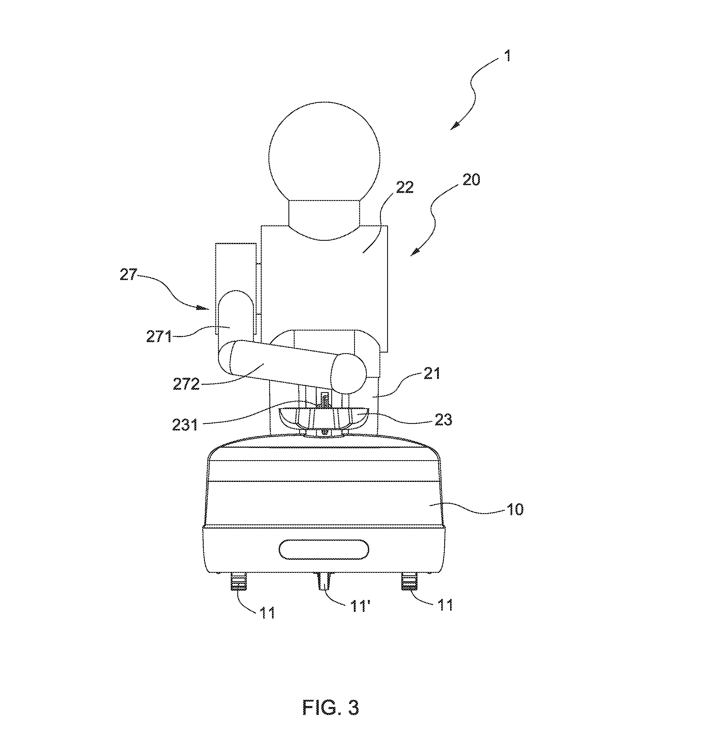
[0013] FIG. 3 is a front schematic view of a robot with a support in accordance with an embodiment of the instant disclosure.
[0014] FIG. 4 is a schematic view showing a linear actuator arranged in a robot with a support in accordance with an embodiment of the instant disclosure.
[0015] FIGS. 5A-5D are schematic views showing that a robot with a support in accordance with an embodiment of the instant disclosure moves/lifts an article.
[0016] FIG. 6 is a perspective schematic view of a robot with a support in accordance with another embodiment of the instant disclosure.
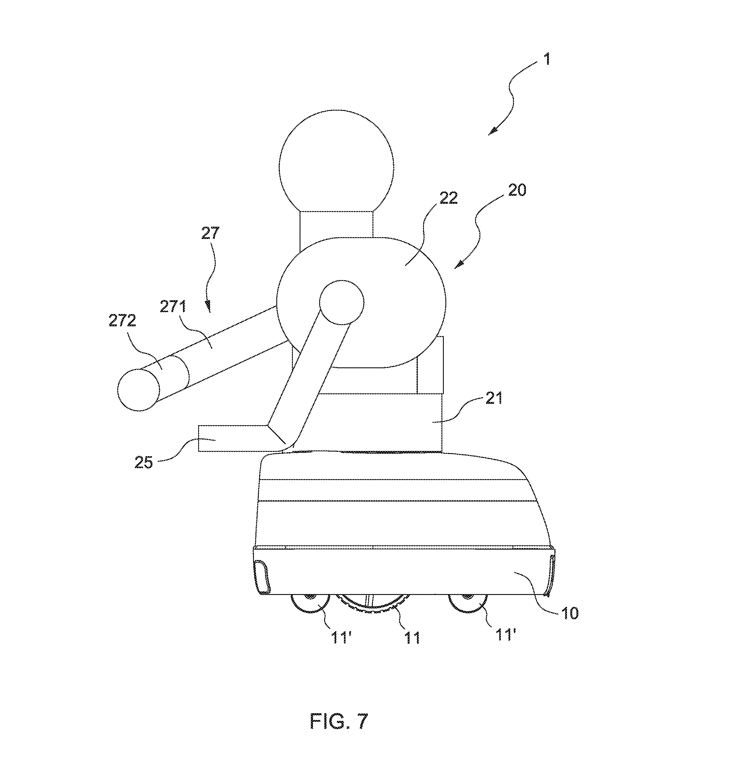
[0017] FIG. 7 is a side schematic view of a robot with a support in accordance with another embodiment of the instant disclosure.
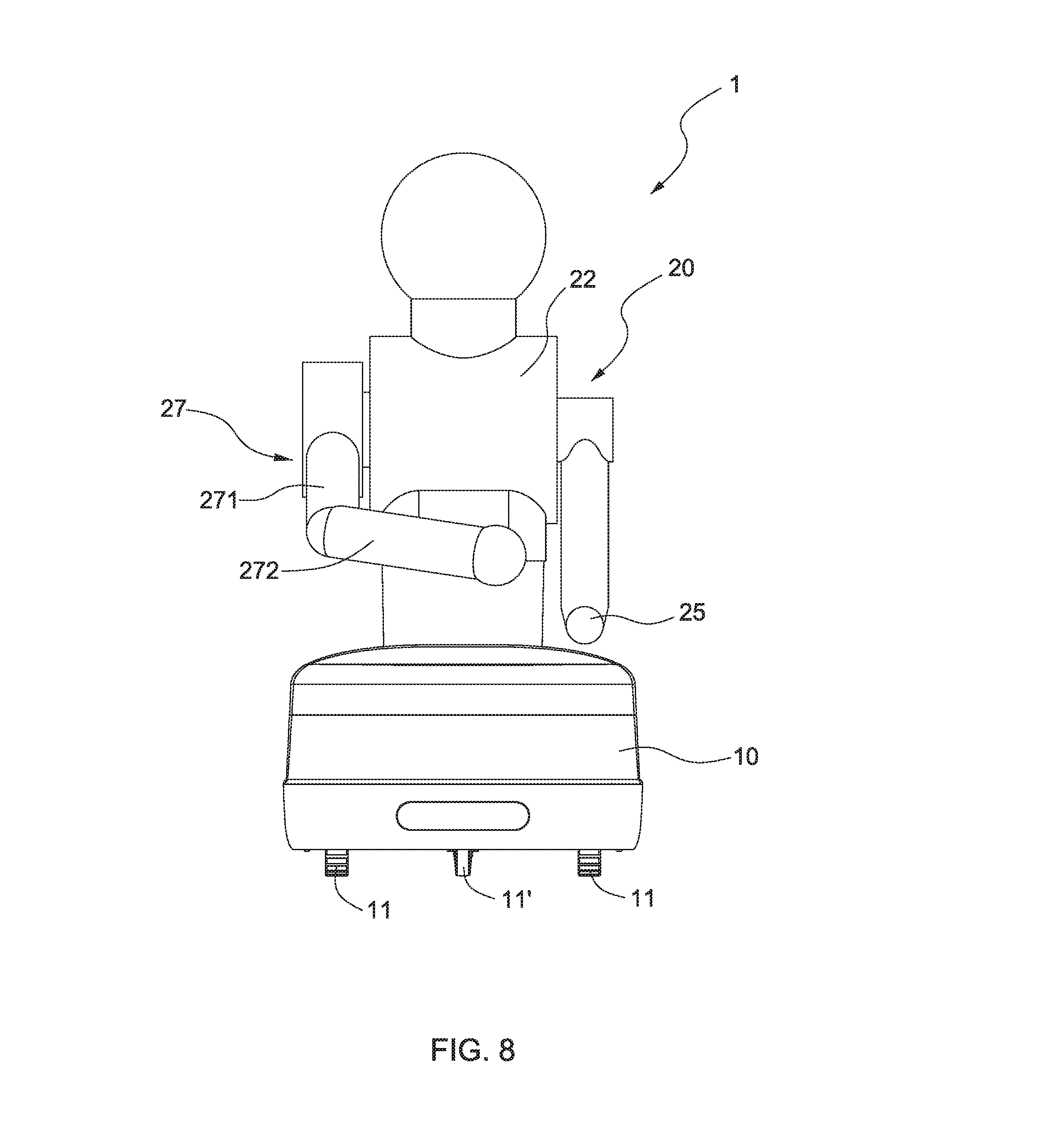
[0018] FIG. 8 is a front schematic view of a robot with a support in accordance with another embodiment of the instant disclosure.
[0019] FIG. 9 is a schematic view showing a linear actuator arranged in a robot with a support in accordance with another embodiment of the instant disclosure.
[0020] FIGS. 10A-10D are schematic views showing that a robot with a support in accordance with another embodiment of the instant disclosure moves/lifts an article.
DETAILED DESCRIPTION OF THE PREFERRED EMBODIMENTS
[0021] The aforementioned illustrations and following detailed descriptions are exemplary for the purpose of further explaining the scope of the instant disclosure. Other objectives and advantages related to the instant disclosure will be illustrated in the subsequent descriptions and appended drawings.
[0022] FIGS. 1, 2 and 3 show a robot with a support in accordance with an embodiment of the instant disclosure. The robot 1 comprises a movable base 10 and a torso 20. The movable base 10 comprises a plurality of wheels 11 and 11' such that the robot 1 could be movable. The torso 20 comprises a lower portion 21 and an upper portion 22. The lower portion 21 is fixedly mounted to the movable base 10. The upper portion 22 is substantially installed to the lower portion 21. Such combination of the lower portion 21 and the second portion causes the torso 20 to be telescopic. Further, the robot 1 comprises a liner actuator 30 (see FIG. 4). The linear actuator 30 will drive the upper portion 22 to move relative to the lower portion 21 and along an axial direction of the torso 20. That is, the torso 20 could be variable in length when the upper portion 22 and the lower portion 21 are moved axially relative to each other in a telescopic manner by the linear actuator 30.
[0023] The robot 1 further comprises a support 23. The support 23 is substantially connected to the upper portion 22 of the torso 20. That is, the support 23 will move upwardly and downwardly when the upper portion 22 moves relative to the lower portion 21. Moreover, the support 23 comprises a joint 231 such that the support 23 could be foldable.
[0024] In addition, the robot 1 further comprises a robotic arm 27. The robotic arm 27 comprises an upper unit 271 and a lower unit 272. One end of the upper unit 271 is substantially connected to one side of the upper portion 22 of the torso 20 and the other end of the upper unit 271 is connected to the lower unit 272. The upper unit 271 has at least one degree of freedom with respect to the upper portion 22 of the torso 20 and the lower unit 272 has at least one degree of freedom with respect to the upper unit 271. Moreover, since the robotic arm 27 is connected to the upper portion 22 of the torso 20, the robotic arm 27 will move upwardly and downwardly when the upper portion 22 moves relative to the lower portion 21.
[0025] FIG. 4 is a schematic view showing a linear actuator arranged in a robot with a support in accordance with an embodiment of the instant disclosure. The linear actuator 30 is arranged within the robot 1 and comprises a motor 31, a gear reducer 32, a screw rod 33 and a lifting platform 34. The motor 31 and the gear reducer 32 are substantially arranged within the movable base 10 and the motor 31 is connected to the gear reducer 32. The screw rod 33 is connected to the gear reducer 32 and axially extends into the interior of the torso 20. More precisely, the screw rod substantially extends along the longitudinal axis of the torso 20. The lifting platform 34 is screwed at the screw rod 33 and fixedly connected to the upper portion 22. Further, referring to FIG. 4, the support 23 is connected to the lifting platform 34.
[0026] When the motor 31 is started, the gear reducer 32 will drive the screw rod 33 to rotate. Once the screw rod 33 rotates, the lifting platform 34 will move along the screw rod 33. Such linear motion of the lifting platform 34 will drive the upper portion 22 and the support 23 to move upwardly or downwardly relative to the lower portion 21. That is, when the liner actuator 30 is actuated, the upper portion 22 is axially moved relative to the lower portion 21 in a telescopic manner and thus the length of the torso 20 is varied. Meanwhile, the support 23 will be moved along with the movement of the second portion 21.
[0027] FIGS. 5A-5D show that a robot with a support in accordance with an embodiment of the instant disclosure moves/lifts an article.
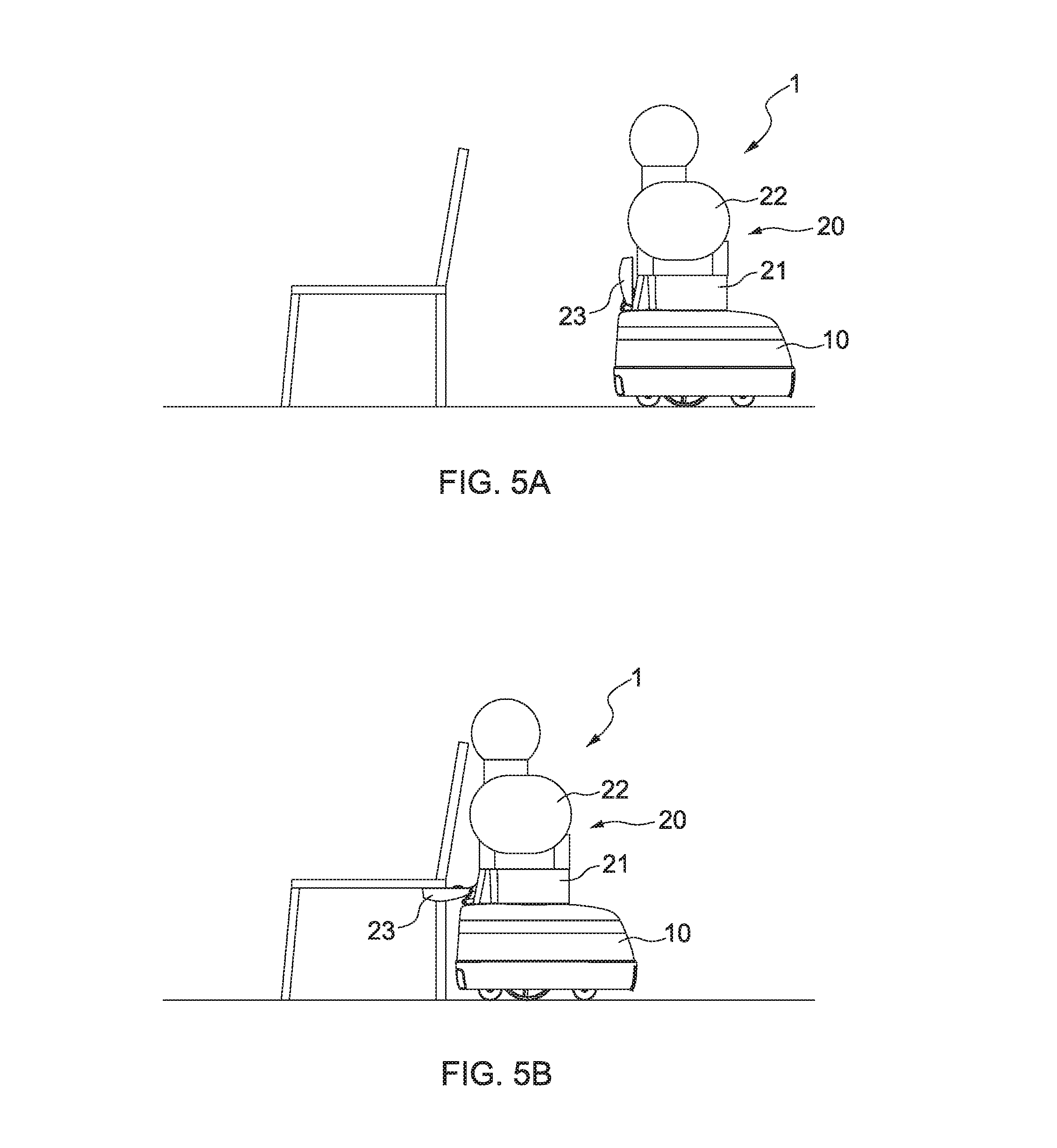
[0028] Referring to FIG. 5A, when the robot 1 will move and/or lift an article, such as a chair 9, the robot 1 will move close to the chair 9 by the movable base 10. As shown in FIG. 5A, since the robot 1 does not lift the chair 9 yet, the support 23 could be foldable so as to be close to the front face of the torso 20.
[0029] Referring to FIG. 5B, when the robot 1 moves close to the chair 9, the support 23 could be unfolded and against the underneath of the chair surface of the chair 9.
[0030] Referring to FIG. 5C, the robot 1 further moves the robotic arm 27 so as to support the chair back of the chair 9. In such a manner, the chair 9 is tightly held by the support 23 and the robotic arm 27 of the robot 1.
[0031] Referring to FIG. 5D, after the chair 9 is tightly held by the support 23 and the robotic arm 27 of the robot 1, the linear actuator 30 is actuated to drive the upper portion 22 to upwardly move relative to the lower portion 21. Meanwhile, the support 23 and the robotic arm 27 move up accordingly. Due to the upward movement of the support 23 and the robotic arm 27, the chair 9 is lifted up by the support 23 and the robotic arm 27 of the robot 1. After the chair 9 is lifted up by the support 23 and the robotic 27 of the robot 1, the robot 1 can further move the chair 9 to a desired place.
[0032] In addition, the robot 1 may further comprise an inertial measurement unit (IMU) sensor (not shown) for measuring the robot's specific force and angular rate during the handling process, or/and a sensor (not shown) for monitoring electrical characteristic of the support 23, or/and an optical sensor (not shown).
[0033] FIGS. 6, 7 and 8 show a robot with a support in accordance with another embodiment of the instant disclosure. The robot 1 comprises a movable base 10 and a torso 20. The movable base 10 comprises a plurality of wheels 11 and 11' such that the robot 1 could be movable. The torso 20 comprises a lower portion 21 and an upper portion 22. The lower portion 21 is fixedly mounted to the movable base 10. The upper portion 22 is substantially installed to the lower portion 21. Such combination of the lower portion 21 and the second portion causes the torso 20 to be telescopic. Further, the robot 1 comprises a liner actuator 30 (see FIG. 4). The linear actuator 30 will drive the upper portion 22 to move relative to the lower portion 21 and along an axial direction of the torso 20. That is, the torso 20 could be variable in length when the upper portion 22 and the lower portion 21 are moved axially relative to each other in a telescopic manner by the linear actuator 30.
[0034] The robot 1 further comprises an arm-like support 25. The support 25 is substantially connected to one side of the upper portion 22 of the torso 20. Thus, the support 25 will move upwardly and downwardly when the upper portion 22 moves relative to the lower portion 21. Further, the support 25 can slightly move relative to the upper portion 22.
[0035] In addition, the robot 1 further comprises a robotic arm 27. The robotic arm 27 comprises an upper unit 271 and a lower unit 272. One end of the upper unit 271 is substantially connected to the other side of the upper portion 22 of the torso 20 and the other end of the upper unit 271 is connected to the lower unit 272. The upper unit 271 has at least one degree of freedom with respect to the upper portion 22 of the torso 20 and the lower unit 272 has at least one degree of freedom with respect to the upper unit 271. Moreover, since the robotic arm 27 is connected to the upper portion 22 of the torso 20, the robotic arm 27 will move upwardly and downwardly when the upper portion 22 moves relative to the lower portion 21.
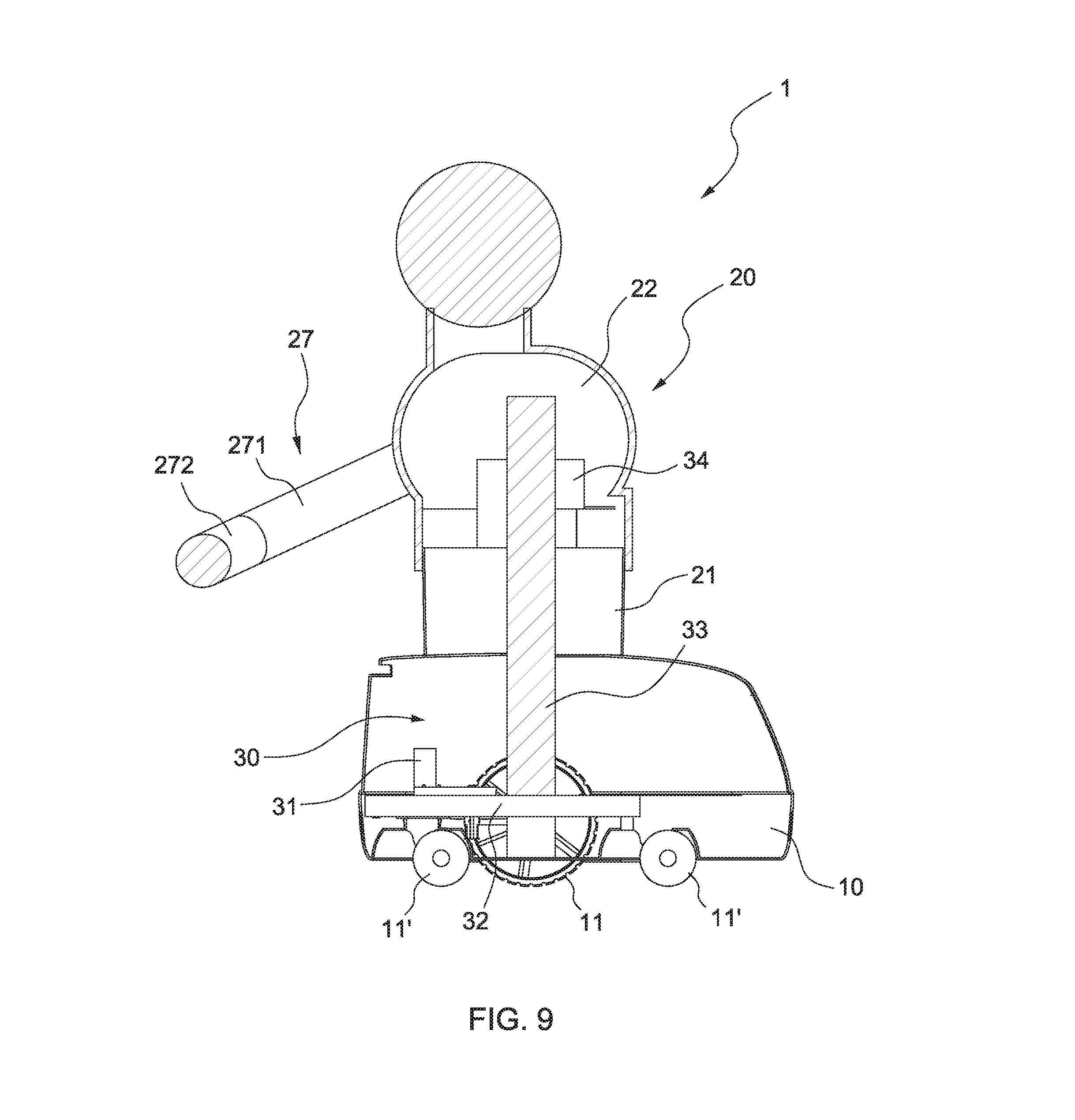
[0036] FIG. 9 is a schematic view showing a linear actuator arranged in a robot with a support in accordance with another embodiment of the instant disclosure. The liner actuator 30 is arranged within the robot 1 and comprises a motor 31, a gear reducer 32, a screw rod 33 and a lifting platform 34. The motor 31 and the gear reducer 32 are substantially arranged within the movable base 10 and the motor 31 is connected to the gear reducer 32. The screw rod 33 is connected to the gear reducer 32 and axially extends into the interior of the torso 20. More precisely, the screw rod substantially extends along the longitudinal axis of the torso 20. The lifting platform 34 is screwed at the screw rod 33 and fixedly connected to the upper portion 22.
[0037] When the motor 31 is started, the gear reducer 32 will drive the screw rod 33 to rotate. Once the screw rod 33 rotates, the lifting platform 34 will move along the screw rod 33. Such linear motion of the lifting platform 34 will drive the upper portion 22 and the support 25 to move upwardly or downwardly relative to the lower portion 21. That is, when the liner actuator 30 is actuated, the upper portion 22 is axially moved relative to the lower portion 21 in a telescopic manner and thus the length of the torso 20 is varied. Meanwhile, the support 25 will be moved along with the movement of the second portion 21.
[0038] FIGS. 10A-10D show that a robot with a support in accordance with another embodiment of the instant disclosure moves/lifts an article.
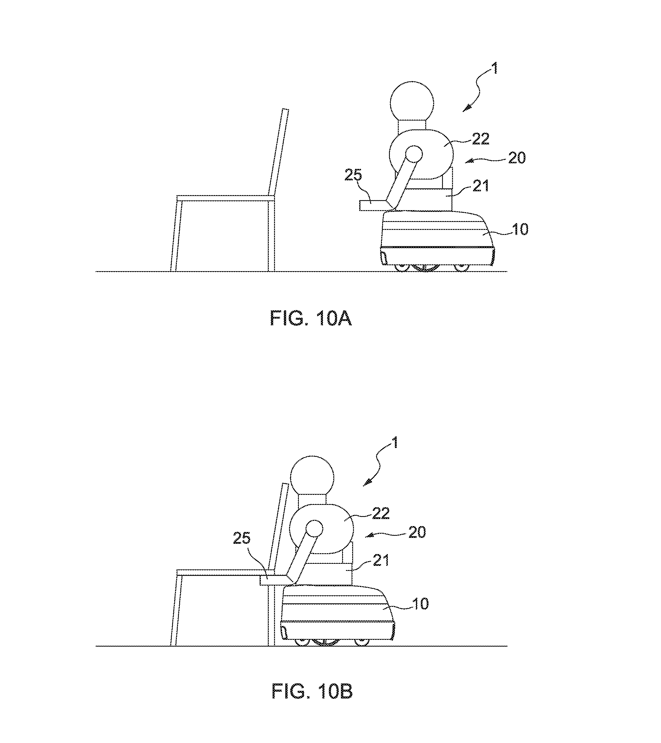
[0039] Referring to FIG. 10A, when the robot 1 will move and/or lift an article, such as a chair 9, the robot 1 will move close to the chair 9 by the movable base 10.
[0040] Referring to FIG. 10B, when the robot 1 moves close to the chair 9, the support 25 could be against the underneath of the chair surface of the chair 9.
[0041] Referring to FIG. 10C, the robot 1 further moves the robotic arm 27 so as to support the chair back of the chair 9. In such a manner, the chair 9 is tightly held by the support 25 and the robotic arm 27 of the robot 1.
[0042] Referring to FIG. 10D, after the chair 9 is tightly held by the support 25 and the robotic arm 27 of the robot 1, the linear actuator 30 is actuated to drive the upper portion 22 to upwardly move relative to the lower portion 21. Meanwhile, the support 25 and the robotic arm 27 move up accordingly. Due to the upward movement of the support 25 and the robotic arm 27, the chair 9 is lifted up by the support 25 and the robotic arm 27 of the robot 1. After the chair 9 is lifted up by the support 25 and the robotic 27 of the robot 1, the robot 1 can further move the chair 9 to a desired place.
[0043] In addition, the robot 1 may further comprise an inertial measurement unit (IMU) sensor (not shown) for measuring the robot's specific force and angular rate during the handling process, or/and a sensor (not shown) for monitoring electrical characteristic of the support 23, or/and an optical sensor (not shown).
[0044] However, the above embodiments merely describe the principle and effects of the present disclosure, instead of being used to limit the present disclosure. Therefore, persons skilled in the art can make modifications and variations to the above embodiments without departing from the spirit of the present disclosure. The scope of the present disclosure should be defined by the appended claims.
* * * * *
D00000
D00001
D00002
D00003
D00004
D00005
D00006
D00007
D00008
D00009
D00010
D00011
D00012

XML
uspto.report is an independent third-party trademark research tool that is not affiliated, endorsed, or sponsored by the United States Patent and Trademark Office (USPTO) or any other governmental organization. The information provided by uspto.report is based on publicly available data at the time of writing and is intended for informational purposes only.
While we strive to provide accurate and up-to-date information, we do not guarantee the accuracy, completeness, reliability, or suitability of the information displayed on this site. The use of this site is at your own risk. Any reliance you place on such information is therefore strictly at your own risk.
All official trademark data, including owner information, should be verified by visiting the official USPTO website at www.uspto.gov. This site is not intended to replace professional legal advice and should not be used as a substitute for consulting with a legal professional who is knowledgeable about trademark law.