Instrumentation Of A Side Wall Of A Continuous Casting Mold With Optical Waveguides
LANG; Oliver ; et al.
U.S. patent application number 16/093209 was filed with the patent office on 2019-07-04 for instrumentation of a side wall of a continuous casting mold with optical waveguides. The applicant listed for this patent is Primetals Technologies Austria GmbH. Invention is credited to Oliver LANG, Guenter LEITNER, Stefan LEITNER, Christian ORTNER, Martin SCHUSTER.
| Application Number | 20190201971 16/093209 |
| Document ID | / |
| Family ID | 58609435 |
| Filed Date | 2019-07-04 |


| United States Patent Application | 20190201971 |
| Kind Code | A1 |
| LANG; Oliver ; et al. | July 4, 2019 |
INSTRUMENTATION OF A SIDE WALL OF A CONTINUOUS CASTING MOLD WITH OPTICAL WAVEGUIDES
Abstract
First, an auxiliary cut-out (11, 16) is formed in a side wall (1) of a continuous casting mold. That cut-out extends, in the longitudinal direction, at least over the cut-out length (L) of the useful cut-out (10) and has an auxiliary cross-section orthogonal to the longitudinal direction. Then, an additional element (13, 14, 17) is inserted into the auxiliary cut-out (11, 16), and extends, in the longitudinal direction, at least over a cut-out length (L) of a later useful cut-out (10) and bounds the useful cut-out (10) orthogonally to the longitudinal direction at least over part of the periphery of the useful cut-out. The useful cut-out (10) is formed by inserting the additional element (13, 14, 17) into the auxiliary cut-out (11, 16). The useful cut-out (10) is closed all around orthogonally to the longitudinal direction. Orthogonally to the longitudinal direction, the useful cut-out has a (correspondingly small) useful cross-section and a maximum useful extent (d3). The useful cross-section is defined in such a way that an optical waveguide (9) can be reversibly inserted into the useful cut-out. The production method makes it possible that a ratio of the cut-out length (L) to the maximum useful extent (d3) is 100:1 or greater.
| Inventors: | LANG; Oliver; (Dietach, AT) ; LEITNER; Guenter; (Freistadt, AT) ; LEITNER; Stefan; (Kollerschlag, AT) ; ORTNER; Christian; (Wilhering, AT) ; SCHUSTER; Martin; (Kopfing, AT) | ||||||||||
| Applicant: |
|
||||||||||
|---|---|---|---|---|---|---|---|---|---|---|---|
| Family ID: | 58609435 | ||||||||||
| Appl. No.: | 16/093209 | ||||||||||
| Filed: | April 25, 2017 | ||||||||||
| PCT Filed: | April 25, 2017 | ||||||||||
| PCT NO: | PCT/EP2017/059766 | ||||||||||
| 371 Date: | October 12, 2018 |
| Current U.S. Class: | 1/1 |
| Current CPC Class: | B22D 11/202 20130101; B22D 11/16 20130101; B22D 2/006 20130101 |
| International Class: | B22D 11/20 20060101 B22D011/20; B22D 2/00 20060101 B22D002/00 |
Foreign Application Data
| Date | Code | Application Number |
|---|---|---|
| Apr 27, 2016 | AT | A50373/2016 |
Claims
1. A method for introducing a useful cut-out into a side wall of a continuous casting mold, wherein the useful cut-out extends over a cut-out length in a longitudinal direction of the useful cut-out, is closed all around orthogonally to the longitudinal direction and has orthogonally to the longitudinal direction a useful cross section and a maximum useful extent, wherein the useful cross section is determined so that an optical waveguide is reversibly insertable into and removable from the useful cut-out; first introducing an auxiliary cut-out into the side wall, wherein the auxiliary cut-out extends at least over the cut-out length of the useful cut-out in the longitudinal direction and the auxiliary cut-out has orthogonally to the longitudinal direction an auxiliary cross section that is greater than the useful cross section; inserting an additional element into the auxiliary cut-out, the additional element is formed as a rod with at least one groove arranged on its outer side or is formed as a tube and the rod or the tube extends at least over the cut-out length of the useful cut-out in the longitudinal direction, wherein inserting the additional element into the auxiliary cut-out, forms the useful cut-out; and wherein, seen orthogonally to the longitudinal direction, the surfaces of the rod that bound the groove also bound the useful cut-out over part of its circumference and the side wall bounds the useful cut-out over the remaining part of its circumference or the inner side of the tube bounds the useful cut-out over its entire circumference.
2. The method as claimed in claim 1, wherein the sidewall has a cold side and a warm side; the method comprising: forming the auxiliary cut-out as a groove that is open toward the cold side of the side wall, only partially filling the auxiliary cut-out toward the cold side with the additional element so that part of the auxiliary cut-out remains toward the cold side, and as seen from the additional element, filling the auxiliary cut-out from the cold side with a filling material.
3. The method as claimed in claim 1, further comprising: forming the auxiliary cut-out as a closed cut-out, seen orthogonally to the longitudinal extent.
4. The method as claimed in claim 3, further comprising the additional element substantially filling the auxiliary cut-out with the additional element.
5. The method as claimed in claim 1, wherein the additional element consists of the same material as the side wall.
6. The method as claimed in claim 1, wherein a ratio of the cut-out length to a maximum useful extent of a useful cut-out is at least 100:1.
7. A side wall of a continuous casting mold, comprising: a useful cut-out in the side wall, the useful cut-out extending over a cut-out length in a longitudinal direction of the useful cut-out, the useful cut-out is closed all around orthogonally to the longitudinal direction and has a useful cross section and a maximum useful extent; wherein the useful cross section is determined such that an optical waveguide is reversibly insertable into the useful cut-out; an additional element is arranged in the side wall, the additional element being formed as a rod with at least one groove arranged on an outer side of the additional element or as a tube that extends at least over the cut-out length of the useful cut-out in the longitudinal direction; seen orthogonally to the longitudinal direction, surfaces of the rod that bound the groove also bound the useful cut-out over part of a circumference thereof, and the side wall bounds the useful cut-out over the remaining part of the circumference thereof or the inner side of the tube bounds the useful cut-out over the entire circumference thereof; and wherein the additional element is completely surrounded by material toward the cold side of the side wall.
8. The side wall as claimed in claim 7, further comprising the additional element is coated toward the cold side with a coating material.
9. The side wall as claimed in claim 7, further comprising: the side wall has an auxiliary cut-out extending at least over the cut-out length of the useful cut-out in the longitudinal direction, the auxiliary cut-out is formed as a closed cut-out, seen orthogonally to the longitudinal extent, and has orthogonally to the longitudinal direction an auxiliary cross section that is greater than the useful cross section, and in that the additional element is inserted into the auxiliary cut-out.
10. The side wall as claimed in claim 9, wherein the auxiliary cut-out is formed as a bore.
11. The side wall as claimed in claim 9, wherein the additional element substantially fills the auxiliary cut-out.
12. The side wall as claimed in claim 7, wherein the additional element consists of the same material as the side wall.
13. The side wall as claimed in claim 7, wherein a ratio of the cut-out length to the maximum useful extent is at least 100:1.
14.-18. (canceled)
Description
CROSS-REFERENCE TO RELATED APPLICATIONS
[0001] The present application is a 35 U.S.C. .sctn..sctn. 371 national phase conversion of PCT/EP2017/059766, filed Apr. 25, 2017, which claims priority of Austrian Patent Application No. A50373/2016, filed Apr. 27, 2016, the contents of which are incorporated by reference herein. The PCT International Application was published in the German language.
TECHNICAL BACKGROUND
[0002] The present invention is based on a method for introducing a useful cut-out into a side wall of a continuous casting mold. The useful cut-out extends over a cut-out length in a longitudinal direction of the useful cut-out, is closed all around orthogonally to the longitudinal direction and has orthogonally to the longitudinal direction a useful cross section and a maximum useful extent, wherein the useful cross section is determined in such a way that an optical waveguide is reversibly insertable into the useful cut-out.
[0003] The present invention is also based on a side wall of a continuous casting mold, [0004] wherein a useful cut-out is introduced into the side wall, which useful cut-out extends over a cut-out length in a longitudinal direction of the useful cut-out, is closed all around orthogonally to the longitudinal direction and has orthogonally to the longitudinal direction a useful cross section and a maximum useful extent, [0005] wherein the useful cross section is determined in such a way that an optical waveguide is reversibly insertable into the useful cut-out.
[0006] During continuous casting, liquid metal is continuously poured into a mold and solidifies on side walls of the mold to form a metal strand comprising an already solidified strand shell and a still liquid core. Synchronously with the pouring of the liquid metal into the mold, the metal strand is drawn off out of the mold. The drawing off of the metal strand is coordinated with the pouring in such a way that a casting level, that is the level of the liquid in the mold, remains substantially constant.
[0007] At the point in time at which the metal strand leaves the mold, the strand shell must already be sufficiently thick. Otherwise, there is the risk of a shell rupture. Decisive for a stable casting process are in particular orderly cooling and a casting rate adapted to the mold. Furthermore, the strand shell must not stick to the mold walls. In particular, such sticking or catching of the shell must be detected in time, since otherwise a shell rupture occurs.
[0008] To detect such sticking, it is known to measure the temperature distribution in the mold by corresponding sensors. Generally, this involves the sensors being arranged in a two-dimensionally distributed manner. The corresponding arrangement of the sensors and their evaluation are known to those skilled in the art.
[0009] Thermocouples may be disturbed by electromagnetic fields. Such disturbing electromagnetic fields may be caused for example by electromagnetic stirrers (MEMS=mold electromagnetic stirrer) or electromagnetic brakes (EBM=electromagnetic brake). Since the use of such electromagnetic stirrers and electromagnetic brakes is increasing, there is an increasing problem of disturbances.
[0010] In order to reduce the electromagnetic disturbances in the case of thermocouples, it is known to twist and shield the lines. Furthermore, filters are often additionally installed, in order to reduce disturbing frequencies. However, both measures generally have a negative influence on the capability of detecting catching of the shell. Furthermore, the installation of many measuring points with thermocouples also quickly encounters structural design limits.
[0011] It is also known in the prior art to detect a temperature value by means of suitable optical waveguides, in particular by means of optical waveguides that are based on the fiber Bragg effect. It is also already known to use such optical waveguides in the case of continuous casting molds.
[0012] For example, reference is made to EP 2 440 883 B1. EP 2 318 162 B1 and JP 2008 043 981 A may also be mentioned in this connection.
[0013] In EP 2 440 883 B1, the optical waveguide is placed onto the side wall of the continuous casting mold. Then a coating is applied to that side of the side wall onto which the optical waveguide has been placed. The coating fixes the optical waveguide. After the fixing, the optical waveguide is undetachably connected to the side wall.
[0014] In EP 2 318 162 B1, the optical waveguide is applied to a probe. The probe is inserted into a groove, a bore or a similar opening and can also be removed from it again. In EP 2 318 162 B1, the optical waveguide is used for the purpose of detecting the height of the casting level. Only a relatively small extent of the optical waveguide in the vertical direction is required for this purpose.
[0015] In JP 2008 043 981 A1, an optical waveguide is surrounded by a metal tube and is secured, including the metal tube, in the side wall of a continuous casting mold.
[0016] WO 2015/058 911 A1 discloses in a first exemplary embodiment introducing a groove into a side wall of a continuous casting mold, placing a first foil onto the groove base, placing a cannula with an optical waveguide onto the first foil, then placing a second foil onto the first foil and the optical waveguide and finally covering or closing the groove with a filler. WO 2015/058 911 A1 also discloses in a second exemplary embodiment introducing into a side wall of a continuous casting mold a bore of a diameter that is slightly greater than the diameter of a cannula containing an optical waveguide and inserting the cannula with the optical waveguide into the bore. WO 2015/058 911 A1 also discloses a third exemplary embodiment introducing into a side wall of a continuous casting mold a bore of a diameter that is considerably greater than the diameter of a cannula containing an optical waveguide and inserting the cannula with the optical waveguide into the bore.
[0017] WO 2011/098 309 A1 discloses introducing into a side wall of a continuous casting mold grooves into which optical waveguides are placed. The grooves are then closed again. The optical waveguides are fixed by hold-down devices.
[0018] DE 10 2010 008 480 A1 discloses introducing into a side wall of a continuous casting mold a groove into which an optical waveguide is placed. The groove is then closed again. The optical waveguide is fixed in the groove.
[0019] WO 03/035 306 A1 discloses introducing into a side wall of a continuous casting mold coolant channels into which displacement rods are then inserted to reduce the cross section.
[0020] JP 2008 260 046 A discloses introducing a bore into the side wall of a mold. An optical waveguide provided with a protective casing is inserted into the bore. A guiding wire may be additionally fixed on the protective casing, and the wire can be inserted together with the optical waveguide into the bore.
SUMMARY OF THE INVENTION
[0021] The object of the present invention is to create possibilities for allowing an optical waveguide to be reversibly inserted into the side wall in an easy way. It is intended that the optical waveguide should in this case be able to extend over a great length, in particular seen in the longitudinal direction of the useful cut-out.
[0022] The object is achieved by a method disclosed herein.
[0023] According to the invention, for introducing the useful cut-out, it is provided [0024] that first an auxiliary cut-out is introduced into the side wall, which auxiliary cut-out extends at least over the cut-out length of the useful cut-out in the longitudinal direction and has orthogonally to the longitudinal direction an auxiliary cross section that is greater than the useful cross section, [0025] that an additional element is inserted into the auxiliary cut-out; the additional element is formed as a rod with at least one groove arranged on its outer side or as a tube and extends at least over the cut-out length of the useful cut-out in the longitudinal direction, [0026] that by inserting the additional element into the auxiliary cut-out, the useful cut-out is formed and [0027] that seen orthogonally to the longitudinal direction, the surfaces of the rod that bound the groove also bound the useful cut-out over part of its circumference and the side wall bounds the useful cut-out over the remaining part of its circumference or the inner side of the tube bounds the useful cut-out over its entire circumference.
[0028] The additional element remains permanently in the side wall. It is connected directly to the side wall. The additional element may alternatively be arranged irreversibly, that is fixedly and non-removably, or reversibly in the side wall. However, in both cases the useful cut-out formed by the additional element represents a remaining cavity into which the optical waveguide can later be reversibly inserted. By this procedure it is possible to create a useful cut-out with a small useful cross section (for example a diameter of about 1.5 to 3.0 mm, in particular of 1.8 to 2.5 mm), the cut-out length extends over the entire, or virtually the entire, height or width of the side wall.
[0029] For example, the auxiliary cut-out may be formed as a groove that is open toward the cold side of the side wall. In this case, the additional element only partially fills the auxiliary cut-out toward the cold side. The part of the auxiliary cut-out remaining toward the cold side, as seen from the additional element, is in this case filled from the cold side with a filling material. The filling material preferably coincides with the material of the side wall toward the hot side. Therefore, if the side wall consists for example of copper (as is regularly the case in particular when continuously casting steel), the filling material is preferably also copper. The same applies in the case a filling of another material. As a result of the filling material, the additional element is completely surrounded on the cold side by the coating material. The cold side is that side of the side wall that is facing away from the liquid metal during the operation of the continuous casting mold. Conversely, the hot side is that side of the side wall that is adjacent to the liquid metal during the operation of the continuous casting mold.
[0030] As an alternative to the auxiliary cut-out being formed as a groove that is open toward the cold side of the side wall, the auxiliary cut-out may be formed as a closed cut-out, seen orthogonally to the longitudinal extent. In particular, the cut-out may be a bore. The bore may for example have a diameter that is as a minimum 6 mm, preferably at least 8 mm, in particular at least 10 mm. As a maximum, the diameter may be up to 20 mm, preferably not exceeding a value of 15 mm, in particular of 12 mm.
[0031] For a closed cut-out, it is for example possible that the additional element substantially fills the auxiliary cut-out.
[0032] The additional element preferably consists of the same material as the side wall. As a result, on the one hand, a uniform coefficient of thermal conduction is obtained, and on the other hand, a uniform coefficient of expansion of the side wall and the additional element is obtained.
[0033] The maximum useful extent is equal to the diameter of a circle circumscribing the useful cross section, that is to say the circle with the smallest diameter that, on the one hand, completely surrounds the useful cross section, and on the other hand, touches the useful cross section, but does not intersect it. In an analogous way, a minimum useful extent is equal to the diameter of a circle inscribed in the useful cross section, that is the circle with the greatest diameter that is completely surrounded by the useful cross section and touches the useful cross section but does not intersect it. The maximum useful extent has for example a value of typically 1.5 mm to 4 mm. The minimum useful extent typically has a value of 1.5 mm to 3 mm. Depending on the type of useful cross section, the minimum useful extent typically lies in the range between 57% and 100% of the maximum useful extent. In a circular useful cross section, the ratio is, for example, 100%. In a square useful cross section, the ratio is, for example, about 71%. By contrast, the cut-out length is considerably greater than the maximum useful extent. It may, for example, be 500 to 800 mm. In particular, it is possible that a ratio of the cut-out length to the maximum useful extent is at least 100:1. Still greater ratios are also possible, for example at least 120:1, at least 150:1, at least 200:1, at least 300:1, at least 400:1 and of at least 500:1. The reason why such a great ratio is achievable is that, because of the manner in which the useful cut-out is produced, the achievable cut-out length is not limited at all in the case of an auxiliary cut-out formed as an open groove, is limited by the transverse extent of the auxiliary cut-out, but not by the transverse extent of the useful cut-out in the case of an auxiliary cut-out formed as a closed cut-out.
[0034] The object is also achieved by a side wall with the features disclosed herein.
[0035] According to the invention, a side wall of the type mentioned at the beginning is developed [0036] in that an additional element is arranged in the side wall, which additional element is formed as a rod with at least one groove arranged on its outer side or is formed as a tube and extends at least over the cut-out length of the useful cut-out in the longitudinal direction, [0037] in that, seen orthogonally to the longitudinal direction, the surfaces of the rod that bound the groove bound the useful cut-out over part of its circumference and the side wall bounds the useful cut-out over the remaining part of its circumference or the inner side of the tube bounds the useful cut-out over its entire circumference and [0038] in that the additional element is completely surrounded by material toward the cold side of the side wall.
[0039] The additional element remains permanently in the side wall. It is connected directly to the side wall. The additional element may alternatively be arranged irreversibly, that is fixedly and non-removably, or reversibly in the side wall. However, in both cases the useful cut-out formed by the additional element represents a remaining cavity into which the optical waveguide can later be reversibly inserted. As a result, the useful cut-out may, as already mentioned, in particular have a small useful cross section, which may for example correspond to a diameter of about 1.5 mm to 3.0 mm, in particular of 1.8 mm to 2.5 mm, while the cut-out length may extend over the entire height or width of the side wall.
[0040] The advantageous developments of the side wall correspond substantially to those of the method.
[0041] For instance, it is possible in particular that the additional element is coated with a coating material toward the cold side, the filling material preferably coinciding with the material of the side wall toward the hot side.
[0042] It is also possible that the side wall has an auxiliary cut-out, which extends at least over the cut-out length of the useful cut-out in the longitudinal direction, is formed as a closed cut-out, seen orthogonally to the longitudinal extent, and has orthogonally to the longitudinal direction an auxiliary cross section that is greater than the useful cross section, and that the additional element is inserted into the auxiliary cut-out. The auxiliary cut-out may in this case be formed in particular as a bore.
[0043] The additional element may substantially fill the auxiliary cut-out.
[0044] The additional element preferably consists of the same material as the side wall.
[0045] As before, it is possible that the useful cut-out has a maximum useful extent, seen orthogonally to the longitudinal direction, and a ratio of the cut-out length to the maximum useful extent is at least 100:1. Here, too, greater ratios are possible, for example at least 120:1, at least 150:1, at least 200:1, at least 300:1, of at least 400:1 and of at least 500:1.
[0046] The properties, features and advantages of this invention described above and the manner in which they are achieved will be more clearly and distinctly comprehensible in conjunction with the following description of the exemplary embodiments, which are explained in greater detail in conjunction with the schematically represented drawings, in which:
BRIEF DESCRIPTION OF THE DRAWINGS
[0047] FIG. 1 shows part of a continuous casting mold from the side,
[0048] FIG. 2 shows a continuous casting mold from above,
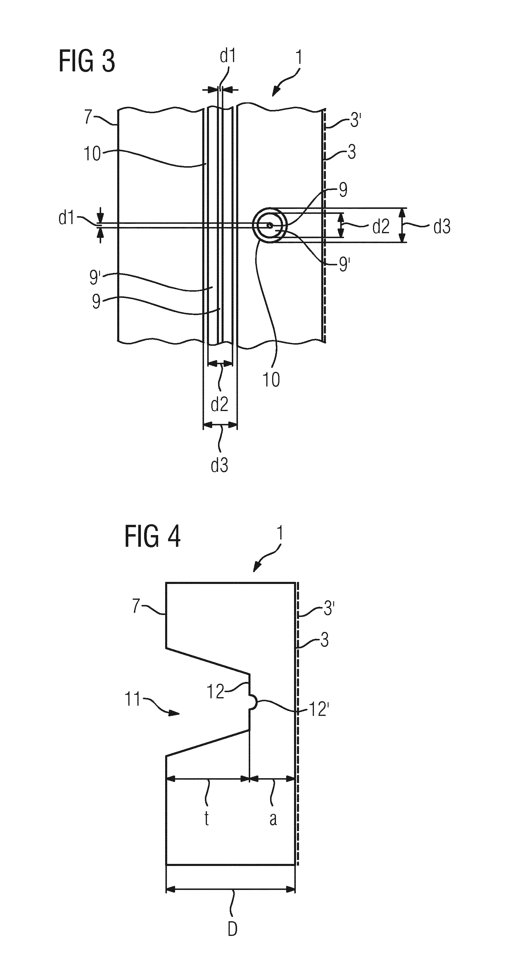
[0049] FIG. 3 shows an enlarged representation of a detail from FIG. 1,
[0050] FIG. 4 shows a side wall with a groove,
[0051] FIG. 5 shows the side wall from FIG. 4 with a tube placed into the groove,
[0052] FIG. 6 shows the side wall from FIG. 4 with a covering placed into the groove,
[0053] FIG. 7 shows a tube,
[0054] FIG. 8 shows the side wall from FIG. 5 in the finished state,
[0055] FIG. 9 shows the side wall from FIG. 6 in the finished state,
[0056] FIG. 10 shows a side wall with a bore and
[0057] FIG. 11 shows the side wall from FIG. 10 in the finished state.
DESCRIPTION OF EMBODIMENTS
[0058] Side walls 1 of a continuous casting mold are used, in a way corresponding to the representation in FIGS. 1 and 2, to bound a liquid metal 2, for example steel or aluminum, while the metal 2 is solidifying on hot sides 3 of the side walls 1 to form a strand shell 4 with a still liquid core 5. The metal strand 6, consisting of the strand shell 4 and the liquid core 5, is drawn off out of the continuous casting mold in a drawing-off direction x. The continuous casting mold may in a way corresponding to the representation in FIGS. 1 and 2, have a number of plates, which together form a rectangular cavity for receiving the liquid metal 2. Alternatively, the continuous casting mold may be formed as an individual, closed side wall 1 completely surrounding the cavity. In many cases, adjusting devices 8, which can set the size of the cavity, are arranged on cold sides 7.
[0059] Further elements of the continuous casting mold are in particular cooling devices, by means of which the side walls 1 are cooled. The cooling devices are not shown in the figures for reasons of overall clarity.
[0060] A height H of the side walls 1 often lies in the range of 50 cm to 2 m. A width B may lie in the range between 20 cm and 3 m. A thickness D usually lies in the range of a few cm, for example 20 mm to 60 mm.
[0061] For the thermal monitoring of the continuous casting mold, optical waveguides 9 are arranged in the side walls 1, as seen in the detail of FIG. 3. The corresponding use of optical waveguides 9 is generally known to those skilled in the art. It is based on the fiber Bragg effect. The optical waveguides 9 may alternatively run horizontally or vertically in the side walls 1. In FIGS. 1 and 2, a horizontally running optical waveguide 9 and a vertically running optical waveguide 9 are respectively shown. There are generally a number of optical waveguides 9, which may for example all run vertically or all run horizontally. However, mixed vertical and horizontal direction or oblique direction forms are also possible. Thus, for reasons of easier assembly and greater operational reliability, it is for example of advantage to insert the optical waveguides 9 horizontally into the side wall 1. Most of the optical waveguides 9 in this case run only horizontally within the side wall 1.
[0062] In order, for example, to be able to detect the height of a casting level exactly, there may be a single further optical waveguide 9, referred to hereinafter as the additional optical waveguide 9. Seen in the direction of the height, the additional optical waveguide 9 must overcome a certain difference in height. This may be achieved on the one hand by the additional optical waveguide 9 running vertically. In this case, the additional optical waveguide 9 is inserted into the side wall 1 from above or from below. Preferably, however, the additional optical waveguide 9 is also inserted laterally into the side wall 1, but runs within the side wall 1 at an angle to the horizontal. The angle is different from 90.degree.. It may for example lie between 10.degree. and 45.degree.. The additional optical waveguide 9 in this case extends over a length such that, with allowance for the angle that it forms with the horizontal, it overcomes the desired difference in height. The difference in height may, for example, be between 80 mm and 150 mm, in particular between 90 mm and 120 mm, for example about 100 mm.
[0063] Customary suitable optical waveguides 9 often have a diameter d1 (FIG. 3), which lies in the range well below 1 mm, for example about 150 .mu.m to 250 .mu.m. The optical waveguides 9 may be surrounded by a protective casing 9'. The protective casing 9' is often also referred to as a cannula. The protective casing 9' often consists of metal, for example high-grade steel. Including the protective casing 9', the optical waveguides 9 often have a diameter d2, which lies in the range of somewhat over 1 mm, for example 1.2 mm to 2.0 mm.
[0064] For receiving the optical waveguides 9, useful cut-outs 10 have been introduced into the side wall 1. The useful cut-outs 10 extend over a respective cut-out length L in a longitudinal direction of the respective useful cut-out 10. The cut-out length L may coincide with the height H or the width B of the respective side wall 1. In this case, it is a continuous, useful cut-out 10, which is open to both sides. Alternatively, the cut-out length L may be shorter. In this case, the useful cut-out 10 ends in the side wall 1 in a way similar to a blind bore. Orthogonally to the longitudinal direction, the useful cut-outs 10 are closed all around. They have orthogonally to the longitudinal direction a cross section and a maximum extent. The cross section and the maximum transverse extent of the useful cut-outs 10 are referred to hereinafter as the useful cross section and the maximum useful extent. This choice of words only serves for verbal differentiation from other cross sections and extents.
[0065] Because the useful cut-outs 10 are intended for receiving the optical waveguides 9, the useful cross section is determined in such a way that one optical waveguide 9 can be respectively inserted into the useful cut-out 10. The optical waveguides 9 may alternatively be inserted into useful cut-outs 10 with the protective casings 9' or without the protective casings 9'. The minimum useful extent must be slightly greater than the diameter of the optical waveguides 9 with or without the protective casings 9'. Accordingly, the minimum useful extent should be above 1.2 mm to 2.0 mm, for example 1.5 mm to 3.0 mm, depending on the optical waveguide that is used. Depending on the form of the useful cross section, the maximum useful extent either has the same value or is slightly greater. In particular, it may lie between 1.5 mm and 4.0 mm. The maximum useful extent should only assume values above 3 mm when this is required to achieve a sufficiently great minimum useful extent.
[0066] The possibility of inserting the optical waveguides 9 into the useful cut-outs 10 is reversible. The optical waveguides 9 can therefore also be removed again from the useful cut-outs 10. Therefore, for a circular useful cross section, the useful cut-outs 10 may, for example, have a diameter d3, which lies in the range between 1.5 mm and 3.0 mm, in particular between 2.0 mm and 2.5 mm. For a circular useful cross section, the diameter d3 corresponds both to the minimum useful extent and to the maximum useful extent. In the case of a square useful cross section, the indicated numerical values may apply for example to the side length of the square shape useful cross section. In the case of a square useful cross section, the maximum useful extent is determined by the diagonal of the square. For the maximum useful cross section, the numerical values are therefore to be provided with a factor of somewhat over 1.4. It is assumed hereinafter that the useful cross section is circular. However, similar circumstances also apply in the case of some other useful cross section.
[0067] As already mentioned, the height H of the side walls 1 often lies in the range from 50 cm to 2 m, and the width B lies in the range between 20 cm and 3 m. As likewise already mentioned, it is possible that the cut-out length L coincides with the height H or the width B of the respective side wall 1. A ratio of the cut-out length L to the maximum useful extent for example the quotient L/d3) can therefore become very large. Although it is possible that the ratio only assumes relatively small values, for example 50 or 80. It is however similarly possible that greater values are assumed, for example 100:1 or more, 120:1 or more, 150:1 or more, and so on. How this can be achieved is explained in more detail below in conjunction with the further FIGS. 4-6.
[0068] For producing at least one useful cut-out 10, first an auxiliary cut-out 11 is introduced into the side wall 1. For example, corresponding to the representation in FIG. 4, a groove 11 may be introduced into the side wall 1 as the auxiliary cut-out 11. The introduction of the groove 11 takes place in this case from the cold side 7 of the side wall 1. The groove 11 is therefore open toward the cold side 7 of the side wall. The groove 11 may for example be formed in a semicircular or V-shaped manner in cross-section. Other forms are also possible. The groove 11 may for example be introduced into the side wall by simple milling or the like. A groove depth t is dimensioned such that the groove base 12 (i.e. the deepest point of the groove 11) is at a predetermined distance a from the hot side 3 of the side wall 1. The auxiliary cut-out 11 extends at least over the cut-out length L of the useful cut-out 10 in the longitudinal direction of the (later) useful cut-out 10. Orthogonally to the longitudinal direction, the auxiliary cut-out 11 has a cross section. The cross section of the auxiliary cut-out 11 is greater than the useful cross section. It is referred to hereinafter as the auxiliary cross section. This choice of words only serves however for verbal differentiation from other cross sections.
[0069] Then, in a way corresponding to the representation in FIGS. 5 and 6, an additional element 13 or 14 is inserted into the auxiliary cut-out 11. The additional element 13, 14 preferably consists of the same material as the side wall 1. If, therefore, the side wall 1 consists of copper, for example, the additional element 13, 14 also consists of copper. Alternatively, the additional element 13, 14 may consist of a material that has similar properties to the material of the side wall 1. This applies in particular to the coefficient of thermal expansion and preferably also to the thermal conductivity.
[0070] The additional element 13 or 14 likewise extends at least over the cut-out length L of the useful cut-out 10 in the longitudinal direction. For example, in a way corresponding to the representation in FIG. 5, the additional element 13 may be formed as a tube 13, the inward side of which bounds the useful cut-out 10. Seen orthogonally to the longitudinal direction, in this case the useful cut-out 10 is completely surrounded or bounded by the additional element 13.
[0071] Alternatively, the additional element 14 may be formed in a way corresponding to the representation in FIG. 6 as a covering 14. In this case, the covering 14 covers the groove base 12. The region between the covering 14 and the groove base 12 corresponds in this case to the useful cut-out 10. Consequently, seen from the useful cut-out 10, the covering 14 is arranged on the cold side 7 of the side wall 1. Seen orthogonally to the longitudinal direction, it partially, but not completely, bounds the useful cut-out 10. In both cases, consequently, the useful cut-out 10 is formed by the insertion of the additional element 13, 14 into the auxiliary cut-out 11.
[0072] The additional element 13 which is developed as a tube 13 may, in a way corresponding to the representation in FIG. 7, consist of a number of portions 13', which are placed one after the other, seen in the longitudinal direction of the useful cut-out 10. The portions 13' may in this case have guiding surfaces 13'' that interact with one another, so that the useful cut-out 10 passes through continuously. Also for example, corresponding to the representation in FIG. 7, the useful cut-out 10 may be slightly widened in the end regions of the portions 13', in order to facilitate the leading in and leading through of the optical waveguide 9 through all of the portions 13'.
[0073] The additional element 13 or 14 only partially fills the auxiliary cut-out 11 or groove 11 toward the cold side 7 of the side wall 1. Depending on the form of the groove 11 and depending on the development of the additional element 13 or 14, the degree of filling may be at greater or smaller values. For example, the degree of filling may lie between 30% and 10%. Sometimes, the degree of filling is even less. In FIGS. 8 and 9, after the insertion of the additional element 13 or 14, the part of the auxiliary cut-out 11 remaining toward the cold side 7 of the side wall 1 is filled from the cold side 7 of the side wall 1 with a filling material 15. This completely surrounds the additional element 13 or 14 by the filling material 15 on the cold side 7 of the side wall 1. In particular, the filling material 15 is cohesively connected to the side wall 1 and the additional element 13 or 14. As a result, the additional element 13, 14 is arranged irreversibly, that is fixedly, permanently and non-removably, in the side wall 1 or in the auxiliary cut-out 11. As a result, the additional element 13 or 14 is connected directly to the side wall 1 without an intermediate space. The additional element 13 or 14 defines a cavity, that is a space, that is not filled with material, into which the optical waveguide 9 can later be reversibly inserted and which cavity is the useful cut-out 10.
[0074] In the ideal case, the filling material 15 coincides with the material of the side wall 1 toward the hot side 3. If the side wall 1 consists, for example, of copper, the filling material is also ideally consists of copper. This also applies whenever the side wall 1 has on the hot side 3 an additional coating 3', for example of nickel, chromium or ceramic. Also in this case, the material of the side wall 1 means the "actual" material of the side wall 1, not the material of the coating 3'. FIGS. 8 and 9 show the corresponding side walls. The filling material 15 is in this case preferably applied by coating to the cold side 7 of the side wall 1. Alternatively, some other material may be used as filling material 15. This applies in particular whenever the groove 11 is relatively narrow. In such cases, nickel, chromium, brass or a synthetic resin may be used for example as the filling material 15. Depending on the situation of the individual case, application by coating may also be possible in this case.
[0075] Any coating applied on the cold side 7 may for example be applied to a thermal spraying process or to a galvanic process. Corresponding processes are generally known to those skilled in the art. For example, as thermal processes there are wire-flame spraying, plasma spraying, powder-vapor spraying, high-velocity flame spraying and cold-gas spraying. What is important for an applied 7 coating is that the filling material 15 be applied as one. If the filling material 15 coincides with the material of the side wall 1 toward the hot side 3, a uniform side wall 1 is formed during the coating, in which a transition from the original side wall 1 to the filling material 15 is not detectable, or is scarcely detectable. Also, the resultant thermal conductivity of the side wall 1, except for the useful cut-out 10, is unchanged with respect to the thermal conductivity of the side wall 1, as it was before the introduction of the groove 11.
[0076] As mentioned above, the groove 11 may be for example be V-shaped or semicircular. Irrespective of the specific form of the groove 11 and corresponding to the representations in FIGS. 5 and 6, a further groove 12' has been introduced into the groove base 12 itself. In the development according to FIG. 5, the additional element 13 is formed as a tube 13, and the further groove 12' may in particular be formed to match the outside diameter of the tube 13. In the development according to FIG. 6, the additional element 14 is formed as a covering 14, and the further groove 12' is preferably determined by the size of the later useful cut-out 10. In particular, in this case, corresponding to the representation in FIG. 5, the covering 14 may be formed as a simple sheet-like covering, which covers the further groove 12'.
[0077] A further possibility for introducing the useful cut-out 10 into the side wall 1 is explained below in conjunction with FIGS. 10 and 11. According to FIGS. 10 and 11, an auxiliary cut-out 16 is introduced into the side wall 1. In FIG. 10, as also in FIGS. 4 to 9, the auxiliary cut-out 16 extends at least over the cut-out length L of the useful cut-out 10 in the longitudinal direction. Also, as in FIGS. 4 to 9, the auxiliary cut-out 16 has, orthogonally to the longitudinal direction, an auxiliary cross section that is greater than the useful cross section. However, in contrast to the development of FIGS. 4 to 9, the auxiliary cut-out 16 of FIGS. 10 and 11 is formed as a closed cut-out, seen orthogonally to the longitudinal extent. For example, the auxiliary cut-out 16 may be a bore with a correspondingly large diameter d4. The diameter d4 may for example lie between 6 mm and 20 mm, and in particular between 8 mm and 15 mm.
[0078] Then, an additional element 17 is inserted into the auxiliary cut-out 16. FIG. 11 shows the corresponding state. The additional element 17 preferably consists of the same material as the side wall 1. The statements made above in relation to the additional elements 13, 14 may be applied in an analogous way.
[0079] The additional element 17 extends at least over the cut-out length L of the useful cut-out 10 in the longitudinal direction. It is preferably formed, corresponding to the representation in FIG. 11, as a rod 17, which substantially fills the auxiliary cut-out 16, but has on its outer side at least one groove 18 extending in the longitudinal direction of the useful cut-out 10. Seen orthogonally to the longitudinal direction, the additional element 17 (or the surfaces of the additional element 17 that bound the groove 18) only bound(s) the useful cut-out 10 over part of its circumference. Over the remaining part of its circumference, the useful cut-out 10 is in this case bounded by the side wall 1. Alternatively, analogous to the development of the tube 13, here, too, the additional element 17 could be formed as a tube in particular, as a multipiece tube. Also in the case of the development of FIGS. 10 and 11, however, the useful cut-out 10 is formed by the insertion of the additional element 17 into the auxiliary cut-out 16.
[0080] When the auxiliary cut-out 16 is closed all around, in particular as a bore, the practically achievable length is limited by the diameter d4. In practice, generally, the depth of an achievable bore can at most be about 100 times the diameter of the bore. This is also applied in the context of the present invention. With a diameter d4 of, for example, 10 mm, a maximum bore depth of about 1000 mm is therefore achievable, with a diameter d4 of, for example 12 mm, a maximum bore depth of about 1200 mm is achievable. With a smaller or greater diameter d4, the achievable bore depth is correspondingly smaller or greater. The achievable bore depth, and consequently the cut-out length L, is limited by the diameter d4 of the auxiliary cut-out 16, but not by the diameter d3 or a dimension equivalent thereto of the useful cut-out 10. It is therefore possible to achieve a great cut-out length L of the useful cut-out 10, although the maximum useful extent of the useful cut-out 10 is small.
[0081] In the minimum case, it is adequate if the additional element has a single groove 18. Alternatively, the additional element 17 may have a plurality of such grooves 18. Various advantageous effects can be realized depending on the number and arrangement of the grooves 18 along the circumference of the additional element 17 and depending on the orientation of the additional element 17 in the auxiliary cut-out 16. For example, corresponding to FIG. 11, there may be two grooves 18 offset by 180.degree. with respect to one another along the circumference. If the additional element 17 is oriented in the auxiliary cut-out 16 such that the two grooves 18 define a plane that runs parallel to the hot side 3 of the side wall 1, a redundancy and/or a spatial resolution can be achieved in the temperature detection. If, on the other hand, the additional element 17 is oriented in the auxiliary cut-out 18 such that the two grooves 18 define a plane that is oriented orthogonally to the hot side 3 of the side wall 1, the temperature gradient can be determined. With, for example, three or four grooves 18, which are distributed uniformly over the circumference of the additional element 17, both effects can be realized.
[0082] In the side wall 1 according to FIGS. 10 and 11, a distance of the additional element 17 from the side wall 1 should be as small as possible (apart from in the region of the groove 18 or the grooves 18), in order to have as little influence as possible on the heat removal from the hot side 3 to the cold side 7 of the side wall 1. This can be achieved by appropriate matching of the diameter of the additional element 17 to the diameter d4 of the auxiliary cut-out 16. For example, a snug fit of the additional element 17 in the auxiliary cut-out 16 may be realized. In this case, after having been inserted into the auxiliary cut-out 16, the additional element 17 can also be removed again from the auxiliary cut-out 16. In this case, although the additional element 17 is not connected cohesively to the side wall 1, it is still connected directly. On account of the additional element 17, there still remains a cavity, that is a space not filled with material, into which the optical waveguide 9 can later be reversibly inserted, that is when the additional element 17 is arranged in the auxiliary cut-out 16, and which cavity is the useful cut-out 10.
[0083] Alternatively, a snug fit of the additional element 17 in the auxiliary cut-out 16 may be achieved for example by the diameter of the additional element 17 being minimally greater than the diameter d4 of the auxiliary cut-out 16, as long as the additional element 17 and the side wall 1 are at the same temperature. In this case, for example, the additional element 17 may be cooled below the temperature of the side wall 1, so that the additional element 17 has thermally shrunk slightly. In addition or as an alternative, the side wall 1 may be heated. In this state, the additional element 17 can then be readily inserted into the auxiliary cut-out 16. The subsequent thermal expansion of the additional element 17 and/or contraction of the side wall 1 has the effect that the additional element 17 comes to bear against the side wall 1 tightly and under pressure. It therefore cannot any longer be removed from the auxiliary cut-out 16. The heat transfer from the side wall 1 into the additional element 17 and vice versa is therefore very good. In particular, the good heat transfer from the side wall 1 into the additional element 17 prevents the side wall 1 from being able to be heated independently of the additional element 17, or the additional element 17 from being able to be cooled down independently of the side wall 1. Otherwise, the above statements made in relation to the case of a snug fit apply.
[0084] The additional element 17 should preferably be secured in the auxiliary cut-out 16 against twisting. In the case of a snug fit, twist prevention is obtained automatically by the pressure under which the additional element 17 lies against the side wall 1. In the case of a snug fit, corresponding securing elements may be present, for example small wedges, are known to a person skilled in the art.
[0085] The present invention has many advantages. In particular, it is possible to produce a side wall 1 of a continuous casting mold into which useful cut-outs 10 with a very small maximum useful extent (for example diameter d3), seen transversely to the longitudinal direction of the useful cut-outs 10, can be introduced over the entire height H or width B or generally over a great cut-out length L in the longitudinal direction of the useful cut-outs 10. This enables optical waveguides 9 with or without a protective casing 9' to be reversibly inserted into the useful cut-outs 10. In particular, in the case of damage to an optical waveguide 9, the damaged optical waveguide 9 can consequently be readily exchanged. This exchangeability is of importance in particular because the failure of an individual optical waveguide leads to the failure of many individual temperature measuring points. It is also possible first to introduce only the useful cut-outs 10 into the side wall 1 and only subsequently, after the forming of the useful cut-outs 10, to insert the optical waveguides, 9 with or without a protective casing 9' into the useful cut-outs 10.
[0086] Although the invention has been illustrated more specifically and described in detail by the preferred exemplary embodiment, the invention is not restricted by the examples disclosed and other variations may be derived therefrom by a person skilled in the art without departing from the scope of protection of the invention.
LIST OF DESIGNATIONS
[0087] 1 Side walls [0088] 2 Liquid metal [0089] 3 Hot sides [0090] 3' Coating [0091] 4 Strand shell [0092] 5 Liquid core [0093] 6 Metal strand [0094] 7 Cold sides [0095] 8 Adjusting devices [0096] 9 Optical waveguide [0097] 9' Protective casing [0098] 10 Useful cut-outs [0099] 11 Auxiliary cut-out (groove) [0100] 12 Groove base [0101] 12' Further groove [0102] 13 Additional element (tube) [0103] 13' Portions [0104] 13'' Guiding surfaces [0105] 14 Additional element (covering) [0106] 15 Filling material [0107] 16 Auxiliary cut-out (bore) [0108] 17 Additional element (rod) [0109] 18 Grooves of the rod [0110] a Distance [0111] B Width [0112] d1 to d4 Diameter [0113] D Thickness [0114] H Height [0115] L Cut-out length [0116] t Groove depth [0117] x Drawing-off direction
* * * * *
D00000
D00001
D00002
D00003
D00004
D00005
XML
uspto.report is an independent third-party trademark research tool that is not affiliated, endorsed, or sponsored by the United States Patent and Trademark Office (USPTO) or any other governmental organization. The information provided by uspto.report is based on publicly available data at the time of writing and is intended for informational purposes only.
While we strive to provide accurate and up-to-date information, we do not guarantee the accuracy, completeness, reliability, or suitability of the information displayed on this site. The use of this site is at your own risk. Any reliance you place on such information is therefore strictly at your own risk.
All official trademark data, including owner information, should be verified by visiting the official USPTO website at www.uspto.gov. This site is not intended to replace professional legal advice and should not be used as a substitute for consulting with a legal professional who is knowledgeable about trademark law.