Handheld Bridge Device For Providing A Communication Bridge Between An Implanted Medical Device And A Smartphone
Balczewski; Ron A. ; et al.
U.S. patent application number 16/239171 was filed with the patent office on 2019-07-04 for handheld bridge device for providing a communication bridge between an implanted medical device and a smartphone. This patent application is currently assigned to CARDIAC PACEMAKERS, INC.. The applicant listed for this patent is CARDIAC PACEMAKERS, INC.. Invention is credited to Ron A. Balczewski, William J. Linder, Keith R. Maile.
| Application Number | 20190201701 16/239171 |
| Document ID | / |
| Family ID | 67057914 |
| Filed Date | 2019-07-04 |


View All Diagrams
| United States Patent Application | 20190201701 |
| Kind Code | A1 |
| Balczewski; Ron A. ; et al. | July 4, 2019 |
HANDHELD BRIDGE DEVICE FOR PROVIDING A COMMUNICATION BRIDGE BETWEEN AN IMPLANTED MEDICAL DEVICE AND A SMARTPHONE
Abstract
A bridge device includes a housing, a plurality of electrodes exposed outside of the housing such that at least two of the plurality of electrodes can be concurrently placed in contact with a patient's skin. A controller is disposed within the housing. A first communications module is operably coupled to the controller and to the at least two of the plurality of electrodes. The first communications module is configured to allow the controller to communicate with an implantable medical device via at least two of the plurality of electrodes using conducted communication. A second communications module is operably coupled to the controller and is configured to allow the controller to communicate with a remote device external to the patient.
| Inventors: | Balczewski; Ron A.; (Bloomington, MN) ; Linder; William J.; (Golden Valley, MN) ; Maile; Keith R.; (New Brighton, MN) | ||||||||||
| Applicant: |
|
||||||||||
|---|---|---|---|---|---|---|---|---|---|---|---|
| Assignee: | CARDIAC PACEMAKERS, INC. St. Paul MN |
||||||||||
| Family ID: | 67057914 | ||||||||||
| Appl. No.: | 16/239171 | ||||||||||
| Filed: | January 3, 2019 |
Related U.S. Patent Documents
| Application Number | Filing Date | Patent Number | ||
|---|---|---|---|---|
| 62613588 | Jan 4, 2018 | |||
| Current U.S. Class: | 1/1 |
| Current CPC Class: | A61N 1/3627 20130101; A61N 1/375 20130101; A61N 1/37235 20130101; A61N 1/3956 20130101; H04M 1/72527 20130101; A61N 1/36514 20130101; A61N 1/3727 20130101; A61B 5/076 20130101; A61B 5/686 20130101; A61N 1/37217 20130101; H04W 4/80 20180201; A61B 5/0402 20130101; A61N 1/37205 20130101; A61N 1/36521 20130101; A61N 1/37223 20130101; A61N 1/37247 20130101; A61N 1/3968 20130101; H04W 84/18 20130101; A61B 5/0028 20130101; A61B 5/0031 20130101; A61N 1/3756 20130101 |
| International Class: | A61N 1/372 20060101 A61N001/372; H04W 4/80 20060101 H04W004/80; H04M 1/725 20060101 H04M001/725; A61N 1/365 20060101 A61N001/365; A61N 1/375 20060101 A61N001/375 |
Claims
1. A bridge device for providing a communication bridge between a leadless cardiac pacemaker and a smartphone, the bridge device comprising: a housing; a plurality of electrodes exposed outside of the housing such that at least two of the plurality of electrodes can be concurrently placed in contact with a patient's skin; a power source disposed within the housing; a controller disposed within the housing and operably powered by the power source; a conducted communications module disposed within the housing and operably coupled to the controller and to the at least two of the plurality of electrodes that can be concurrently placed in contact with a patient's skin, the conducted communications module configured to allow the controller to communicate with a leadless cardiac pacemaker via at least two of the plurality of electrodes that can be concurrently placed in contact with a patient's skin using conducted communication; and a RF communications module disposed within the housing and operably coupled to the controller, the RF communications module configured to allow the controller to communicate with a smartphone external to the patient using RF communication.
2. The bridge device of claim 1, further comprising a memory operably coupled to the controller such that information received from the leadless cardiac pacemaker by conducted communication via the at least two of the plurality of electrodes can be saved to the memory prior to subsequent communication of the information to the smartphone via the RF communications module.
3. The bridge device of claim 1, further comprising one or more sensors operatively coupled to the controller for sensing one or more sensed parameters, wherein the controller is configured to communicate the one or more sensed parameters to the smartphone via the RF communications module.
4. The bridge device of claim 3, wherein the one or more sensors comprise one or more of an accelerometer, a gyroscope, an impendence sensor, an electrogram sensor, a force sensor, an audio sensor and a button.
5. The bridge device of claim 1, further comprising a user interface operably coupled to the controller, wherein the controller is configured to communicate with the patient via the user interface, wherein the user interface comprises one or more of a vibrator, a speaker and a Light Emitting Diode (LED).
6. A bridge device for providing a communication bridge between an implantable medical device configured to sense cardiac electrical activity of a patient's heart and a remote device external to the patient, the bridge device comprising: a housing; a plurality of electrodes exposed outside of the housing such that at least two of the plurality of electrodes can be concurrently placed in contact with a patient's skin; a power source disposed within the housing; a controller disposed within the housing and operably powered at least in part by the power source; a first communications module disposed within the housing and operably coupled to the controller and to the at least two of the plurality of electrodes that can be concurrently placed in contact with a patient's skin, the first communications module configured to allow the controller to communicate with an implantable medical device via at least two of the plurality of electrodes that can be concurrently placed in contact with a patient's skin using conducted communication; and a second communications module disposed within the housing and operably coupled to the controller, the second communications module configured to allow the controller to communicate with a remote device external to the patient.
7. The bridge device of claim 6, wherein the implantable medical device is a leadless cardiac pacemaker and the remote device is a smartphone.
8. The bridge device of claim 6, wherein the second communications module is configured to allow the controller to communicate with the remote device external to the patient using wireless communication.
9. The bridge device of claim 8, wherein the wireless communication comprises Radio Frequency (RF) communication.
10. The bridge device of claim 8, wherein the wireless communication comprises one or more of bluetooth communication, WiFi communication, inductive communication, infrared (IR) communication and optical communication.
11. The bridge device of claim 6, wherein the second communications module is configured to allow the controller to communicate with the remote device external to the patient using wired communication.
12. The bridge device of claim 6, further comprising one or more sensors operatively coupled to the controller for sensing one or more sensed parameters, wherein the controller is configured to communicate the one or more sensed parameters to the remote device external to the patient via the second communications module.
13. The bridge device of claim 12, wherein the one or more sensors comprise one or more of an accelerometer, a gyroscope, an impendence sensor, an electrogram sensor, a force sensor, an audio sensor and a button.
14. The bridge device of claim 6, further comprising a user interface operably coupled to the controller, wherein the controller is configured to communicate with the patient via the user interface, wherein the user interface comprises one or more of a vibrator, a speaker and a Light Emitting Diode (LED).
15. The bridge device of claim 6, wherein the housing has a first side and an opposing second side, and wherein the first side has at least two of the plurality of electrodes.
16. The bridge device of claim 15, wherein the second side has at least two of the plurality of electrodes.
17. The bridge device of claim 15, wherein the housing has a side wall extending between the first side and the second side, wherein the side wall has at least one of the plurality of electrodes.
18. The bridge device of claim 15, wherein the first side has at least four electrodes arranged in a kite configuration.
19. An external bridge device configured to serve as a communications bridge between a medical device implantable within a patient and a remote device exterior to the patient, the external bridge device configured to communicate with the medical device implantable within a patient via conducted communication and to communicate with the remote device exterior to the patient using a wireless communications protocol, the external bridge device comprising: a substrate; two or more electrodes disposed on the substrate such that the two or more electrodes are configured to be temporarily disposed in contact with the patient's skin; a controller operably coupled to the two or more electrodes and configured to receive conducted communication from the medical device implantable within a patient via two of the two or more electrodes; a transceiver operable coupled to the controller; and the controller configured to receive information via conducted communication and to transmit the information to the remote device exterior to the patient via the transceiver.
20. The external bridge device of claim 20, further comprising one or more sensors operatively coupled to the controller for sensing one or more sensed parameters, wherein the controller is configured to communicate the one or more sensed parameters to the remote device via the transceiver.
Description
CROSS REFERENCE TO RELATED APPLICATIONS
[0001] This application claims the benefit of U.S. Provisional Patent Application Ser. No. 62/613,588 filed on Jan. 4, 2018, the disclosure of which is incorporated herein by reference.
TECHNICAL FIELD
[0002] The present disclosure pertains to medical devices, and more particularly to medical devices that are configured to communicate with an implanted medical device such as leadless cardiac pacemaker as well as an external device such as a smartphone.
BACKGROUND
[0003] Implantable medical devices are commonly used today to monitor physiological or other parameters of a patient and/or deliver therapy to a patient. In one example, to help patients with heart related conditions, various medical devices (e.g., pacemakers, defibrillators, sensors, etc.) can be implanted in a patient's body. Such devices may monitor and in some cases provide electrical stimulation (e.g. pacing, defibrillation, etc.) to the heart to help the heart operate in a more normal, efficient and/or safe manner. In some cases, there is a desire to obtain information from and/or provide commands to an implantable medical device.
SUMMARY
[0004] The present disclosure pertains to medical devices, and more particularly to medical devices that are configured to communicate with an implanted medical device such as leadless cardiac pacemaker as well as an external device such as a smartphone. In some cases, the present disclose provides a handheld bridge device for providing a communication bridge between the implanted medical device and the device that is external to the patient.
[0005] In a particular example of the disclosure, a handheld bridge device provides a communication bridge between a leadless cardiac pacemaker and a smartphone. The illustrative bridge device includes a housing and a plurality of electrodes that are exposed outside of the housing such that at least two of the plurality of electrodes can be concurrently placed in contact with a patient's skin. A power source is disposed within the housing. A controller is disposed within the housing and is operably powered by the power source. In some cases, the bridge device includes a conducted communications module that is disposed within the housing and is operably coupled to the controller and to the at least two of the plurality of electrodes that can be concurrently placed in contact with a patient's skin. The conducted communications module is configured to allow the controller to communicate with a leadless cardiac pacemaker via at least two of the plurality of electrodes that can be concurrently placed in contact with a patient's skin using conducted communication. The illustrative bridge device may further include a RF communications module that is disposed within the housing and operably coupled to the controller. The RF communications module may be configured to allow the controller to communicate with a smartphone external to the patient using RF communication. In some cases, the bridge device may provide a communication bridge between the leadless cardiac pacemaker and the smartphone such that the leadless cardiac pacemaker can provide information/data to the smartphone and/or the smartphone may provide commands and/or requests to the leadless cardiac pacemaker. It is contemplated that the bridge device may provide one-way or bi-directional communication.
[0006] Alternatively or additionally, the bridge device may further include a memory that is operably coupled to the controller such that information received from the leadless cardiac pacemaker by conducted communication via the at least two of the plurality of electrodes can be saved to the memory prior to subsequent communication of the information to the smartphone via the RF communications module.
[0007] Alternatively or additionally, the bridge device may further include one or more sensors operatively coupled to the controller for sensing one or more sensed parameters, wherein the controller is configured to communicate the one or more sensed parameters to the smartphone via the RF communications module.
[0008] Alternatively or additionally, the one or more sensors may include one or more of an accelerometer, a gyroscope, an impendence sensor, an electrogram sensor, a force sensor, an audio sensor and a button.
[0009] Alternatively or additionally, the bridge device may further include a user interface that is operably coupled to the controller. The controller may be configured to communicate with the patient via the user interface and the user interface may include one or more of a vibrator, a speaker and a Light Emitting Diode (LED).
[0010] In another example of the disclosure, a bridge device provides a communication bridge between an implantable medical device that is configured to sense cardiac electrical activity of a patient's heart and a remote device that is external to the patient. The bridge device includes a housing and a plurality of electrodes that are exposed outside of the housing such that at least two of the plurality of electrodes can be concurrently placed in contact with a patient's skin. A power source is disposed within the housing, as is a controller that is operably powered at least in part by the power source. The bridge device includes a first communications module that is disposed within the housing and operably coupled to the controller and to the at least two of the plurality of electrodes that can be concurrently placed in contact with a patient's skin, the first communications module being configured to allow the controller to communicate with an implantable medical device via at least two of the plurality of electrodes that can be concurrently placed in contact with a patient's skin using conducted communication. A second communications module is disposed within the housing and is operably coupled to the controller, the second communications module being configured to allow the controller to communicate with a remote device external to the patient.
[0011] Alternatively or additionally, the implantable medical device may be a leadless cardiac pacemaker and the remote device may be a smartphone.
[0012] Alternatively or additionally, the second communications module may be configured to allow the controller to communicate with the remote device external to the patient using wireless communication.
[0013] Alternatively or additionally, the wireless communication may include Radio Frequency (RF) communication.
[0014] Alternatively or additionally, the wireless communication may include one or more of bluetooth communication, WiFi communication, inductive communication, infrared (IR) communication and optical communication.
[0015] Alternatively or additionally, the second communications module may be configured to allow the controller to communicate with the remote device external to the patient using wired communication.
[0016] Alternatively or additionally, the bridge device may further include one or more sensors that are operatively coupled to the controller for sensing one or more sensed parameters, wherein the controller is configured to communicate the one or more sensed parameters to the remote device external to the patient via the second communications module.
[0017] Alternatively or additionally, the one or more sensors may include one or more of an accelerometer, a gyroscope, an impendence sensor, an electrogram sensor, a force sensor, an audio sensor and a button.
[0018] Alternatively or additionally, the bridge device may further include a user interface that is operably coupled to the controller. The controller may be configured to communicate with the patient via the user interface and the user interface may include one or more of a vibrator, a speaker and a Light Emitting Diode (LED).
[0019] Alternatively or additionally, the housing may have a first side and an opposing second side, and the first side may have at least two of the plurality of electrodes.
[0020] Alternatively or additionally, the second side may have at least two of the plurality of electrodes.
[0021] Alternatively or additionally, the housing may have a side wall extending between the first side and the second side and the side wall may have at least one of the plurality of electrodes.
[0022] Alternatively or additionally, the first side may have at least four electrodes arranged in a kite configuration.
[0023] In another example of the disclosure, an external bridge device may be configured to serve as a communications bridge between a medical device implantable within a patient and a remote device exterior to the patient, the external bridge device configured to communicate with the medical device implantable within a patient via conducted communication and to communicate with the remote device exterior to the patient using a wireless communications protocol. The external bridge device includes a substrate and two or more electrodes that are disposed on the substrate such that the two or more electrodes are configured to be temporarily disposed in contact with the patient's skin. A controller is operably coupled to the two or more electrodes and is configured to receive conducted communication from the medical device implantable within a patient via two of the two or more electrodes. A transceiver is operable coupled to the controller. The controller is configured to receive information via conducted communication and to transmit the information to the remote device exterior to the patient via the transceiver.
[0024] Alternatively or additionally, the external bridge device may further include one or more sensors that are operatively coupled to the controller for sensing one or more sensed parameters, wherein the controller is configured to communicate the one or more sensed parameters to the remote device via the transceiver.
[0025] The above summary of some illustrative embodiments is not intended to describe each disclosed embodiment or every implementation of the present disclosure. The Figures, and Description, which follow, more particularly exemplify some of these embodiments.
BRIEF DESCRIPTION OF THE DRAWINGS
[0026] The disclosure may be more completely understood in consideration of the following description in connection with the accompanying drawings, in which:
[0027] FIG. 1 is a schematic block diagram of a system including an implantable medical device (IMD), an external device and a bridge device to facilitate communication between the IMD and the external device in accordance with an example of the disclosure;
[0028] FIG. 2 is a schematic block diagram of a bridge device useable in the system of FIG. 1 in accordance with an example of the disclosure;
[0029] FIG. 3 is a schematic block diagram of a bridge device useable in the system of FIG. 1 in accordance with an example of the disclosure;
[0030] FIG. 4 is a schematic block diagram of a bridge device useable in the system of FIG. 1 in accordance with an example of the disclosure;
[0031] FIG. 5 is a perspective view of a bridge device useable in the system of FIG. 1 in accordance with an example of the disclosure;
[0032] FIG. 6 is a schematic block diagram of a bridge device useable in the system of FIG. 1 in accordance with an example of the disclosure;
[0033] FIG. 7 is a schematic block diagram of a bridge device useable in the system of FIG. 1 in accordance with an example of the disclosure;
[0034] FIG. 8 is a schematic block diagram of a bridge device useable in the system of FIG. 1 in accordance with an example of the disclosure;
[0035] FIG. 9 is a schematic view of a bridge device deployed relative to a patient's chest and touching the patient's skin;
[0036] FIG. 10 is a schematic view of a bridge device deployed in a patient's hands;
[0037] FIG. 11 is a schematic block diagram of an illustrative IMD in accordance with an example of the disclosure; and
[0038] FIG. 12 is a schematic block diagram of another illustrative medical device in accordance with an example of the disclosure.
[0039] While the disclosure is amenable to various modifications and alternative forms, specifics thereof have been shown by way of example in the drawings and will be described in detail. It should be understood, however, that the intention is not to limit the disclosure to the particular embodiments described. On the contrary, the intention is to cover all modifications, equivalents, and alternatives falling within the spirit and scope of the disclosure.
DESCRIPTION
[0040] For the following defined terms, these definitions shall be applied, unless a different definition is given in the claims or elsewhere in this specification.
[0041] All numeric values are herein assumed to be modified by the term "about," whether or not explicitly indicated. The term "about" generally refers to a range of numbers that one of skill in the art would consider equivalent to the recited value (i.e., having the same function or result). In many instances, the terms "about" may include numbers that are rounded to the nearest significant figure.
[0042] The recitation of numerical ranges by endpoints includes all numbers within that range (e.g. 1 to 5 includes 1, 1.5, 2, 2.75, 3, 3.80, 4, and 5).
[0043] As used in this specification and the appended claims, the singular forms "a", "an", and "the" include plural referents unless the content clearly dictates otherwise. As used in this specification and the appended claims, the term "or" is generally employed in its sense including "and/or" unless the content clearly dictates otherwise.
[0044] It is noted that references in the specification to "an embodiment", "some embodiments", "other embodiments", etc., indicate that the embodiment described may include one or more particular features, structures, and/or characteristics. However, such recitations do not necessarily mean that all embodiments include the particular features, structures, and/or characteristics. Additionally, when particular features, structures, and/or characteristics are described in connection with one embodiment, it should be understood that such features, structures, and/or characteristics may also be used connection with other embodiments whether or not explicitly described unless clearly stated to the contrary.
[0045] The following description should be read with reference to the drawings in which similar structures in different drawings are numbered the same. The drawings, which are not necessarily to scale, depict illustrative embodiments and are not intended to limit the scope of the disclosure. While the present disclosure is applicable to any suitable implantable medical device (IMD), the description below often uses leadless cardiac pacemakers (LCP) and implantable cardioverter-defibrillator (ICD) and/or pacemakers as particular examples.
[0046] FIG. 1 is a schematic block diagram of a system that includes an implantable medical device (IMD) 12, an external device 14 and a handheld bridge device 16 to facilitate communication between the IMD 12 and the external device 14 in accordance with an example of the disclosure. In some cases, the IMD 12 may sense and/or pace a heart H. In some cases, the IMD 12 may be configured to shock the heart H. In some cases, the IMD 12 may be a diagnostic sensor that is configured to capture and provide diagnostic data, sometimes to the external device 14 via the bridge device 16.
[0047] In the example shown, the implantable medical device (IMD) 12 may be deployed near or even within the heart H. The implanted location of the IMD 12 may be considered as being an implant site. As illustrated, the IMD 12 is shown implanted in the right ventricle LV. This is merely illustrative, as the IMD 12 may be implanted within any other chamber of the heart H, or may be implanted within the patient but external to the heart H.
[0048] In some cases, there may be a desire to communicate with the IMD 12. For example, there may be a desire to transfer sensor data and other cardiac-related information that may be sensed by the IMD 12 to an external device 14. In some cases, due to its proximity to the heart H, the IMD 12 may be in a position to obtain more accurate cardiac electrical signals than can be obtained from skin electrodes or the like. In some instances, there may be a desire to upload at least some of this information so that it can be more easily viewed and/or analyzed. In some cases, there may be a desire to transmit cardiac data from the IMD 12 so that a remote physician or monitoring service can see how the patient is doing, which may allow routine periodic reviews as well as reviews during particular situations in which the patient is not feeling well. In some cases, it may be desirable to send commands and/or requests to the IMD 12 from an external device 14. In some cases, the IMD 12 may be a Leadless Cardiac Pacemaker (LCP) that is configured to communicate with other devices using conducted communication.
[0049] The external device 14 may be any device external to the patient that is configured to receive, send and/or analyze information. In some cases, the external device 14 may be configured to display cardiac data received from the IMD 12 via the handheld bridge device 16. In some instances, the external device 14 may be used to transmit parameters and other configuration data to the IMD 12 via handheld bridge device 16 in order to control or optimize operation of the IMD 12. In some cases, the external device 14 may be a programmer. In some cases, the external device 14 may be a portable device such as a tablet or smartphone that can receive cardiac data and/or other information from the IMD 12 via handheld bridge device 16, and can then display the cardiac data and/or other information and/or communicate the cardiac data and/or other information elsewhere via a cellular network, WiFi, Bluetooth and the like. In some cases, the external device 14 may be a gateway or the like (e.g. router and/or access point) that can receive the cardiac data and/or other information from the IMD 12 via the handheld bridge device 16 and transmit the data and/or other information to a remote server or the like, such as a remote server that is accessible by a physician.
[0050] In some instances, the communication protocols used by the IMD 12 and the external device 14 may be different, and may not be compatible with each other. For example, in some cases, the IMD 12 may be configured to communicate via conducted communication while the external device 14 may use a wireless communication protocol. In conducted communication, electrical signals are transmitted or carried from the transmitter to the receiver via body tissue. While this enables communication between implanted devices, receiving conducted communication from outside the body typically requires physical contact with the patient's skin in order to pick up the electrical impulses carried by the body tissue. As illustrated, the system 10 may include a bridge device 16. As will be discussed, the bridge device 16 may be handheld and may include electrical contacts that can be presses against the patient's skin, and when so provided, communicate with the IMD 12 via conducted communication. The bridge device may also be configured to communicate with the external device 14 via a wireless or wired communication protocol (e.g. RF communication, IR communication, inductive communication).
[0051] It will be appreciated that communication between the external device 14 and the bridge device 16 may be unidirectional or bidirectional, and communication between the bridge device 16 and the IMD 12 may be unidirectional or bidirectional. In some cases, the IMD 12 may be configured to periodically transmit particular data, and if the bridge device 16 is in skin contact, the bridge device 16 may receive the transmitted data. In some instances, the IMD 12 may only transmit particular data after receiving a request for the data from the bridge device 16. In some cases, the request may originate in the external device 14 and may be transmitted via conducted communication to the IMD 12 via the bridge device 16. In some cases, the bridge device 16 may include one or more sensors, such as an ECG sensor, an accelerometer, a resistance sensor, a gyroscope, and/or any other suitable sensor or sensor combination, and may provide the sensed data to the external device 14 and/or IMD 12.
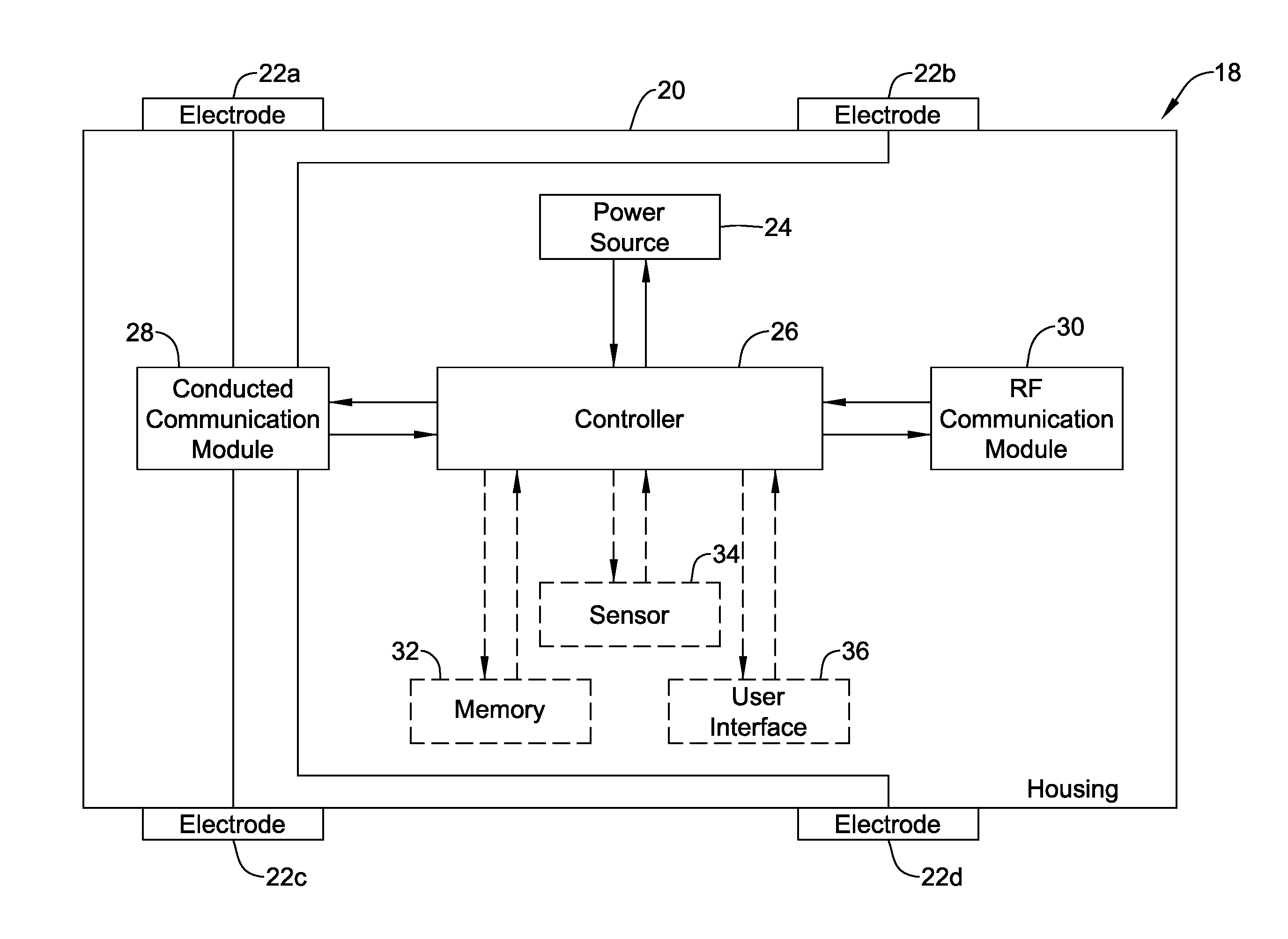
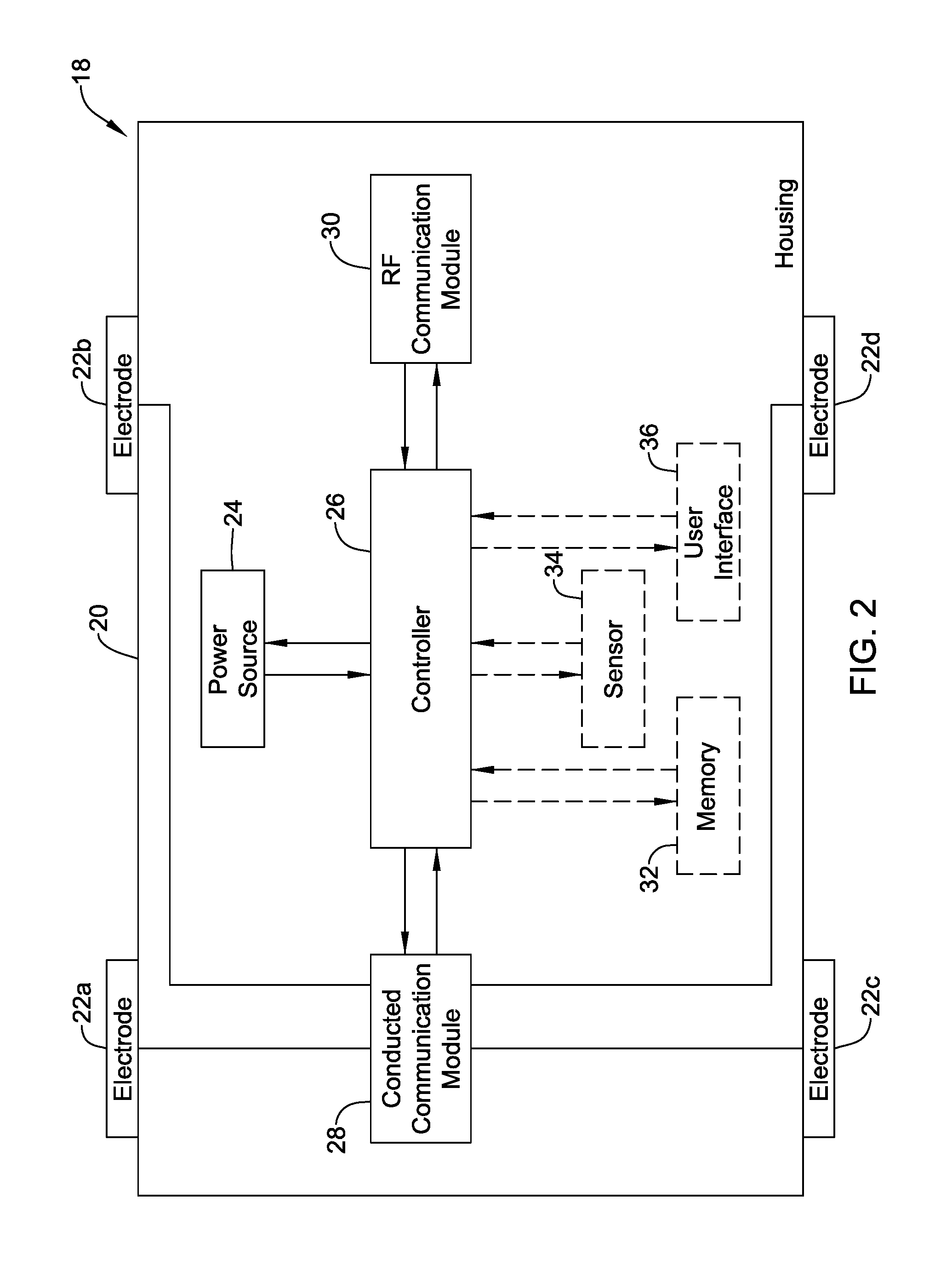
[0052] FIG. 2 is a schematic block diagram of an illustrative bridge device 18 that may be considered as being a manifestation of the bridge device 16 (FIG. 1). The bridge device 18 may be considered as providing a communication bridge between a leadless cardiac pacemaker (an example of the IMD 12) and a smartphone (an example of the external device 14). In some cases, the bridge device 18 may be handheld and may include a housing 20 and a plurality of electrodes 22a, 22b, 22c, 22d that are exposed outside of the housing 20. In some cases, at least two of the plurality of electrodes 22a, 22b, 22c, 22d are positioned so that they can be concurrently placed in contact with a patient's skin. While a total of four electrodes 22a, 22b, 22c, 22d are illustrated in FIG. 2, it will be appreciated that in some cases, there may be only two electrodes, or three electrodes. In some cases, there may be five or more electrodes on the housing 20.
[0053] In some cases, having multiple electrodes enables additional communication vectors for communicating with the IMD 12. In some instances, having multiple electrodes enables Kelvin sensing in which a first pair of electrodes is used to provide a current and a second pair of electrodes is used to sense a resulting voltage. The illustrative bridge device 18 also includes a power source 24 that is disposed within the housing 20. The power source 24 may be a rechargeable battery or a non-rechargeable battery, for example, or a capacitor. A controller 26 is also disposed within the housing 20 and is operably powered by the power source 24. In some cases, the controller 26 may be configured to sequentially test various communication vectors using various pairs of the electrodes 22a, 22b, 22c, 22d, and may select a particular communication vector that, for example provides the highest signal-to-noise ratio (SNR) for subsequent use.
[0054] In the example shown, a conducted communications module 28 is disposed within the housing 20 and is operably coupled to the controller 26 and to at least two of the plurality of electrodes 22a, 22b, 22c, 22d. In some cases, the conducted communications module 28 is configured to allow the controller 26 to communicate with a leadless cardiac pacemaker (such as the IMD 12 of FIG. 1) via at least two of the plurality of electrodes 22a, 22b, 22c, 22d using conducted communication. In the example shown, an RF communications module 30 is also disposed within the housing 20 and is operably coupled to the controller 26. In some cases, the RF communications module 30 is configured to allow the controller 26 to communicate with a smartphone (as an example of the external device 14) external to the patient using RF communication (e.g. WiFi, Bluetooth, etc.).
[0055] In some cases, the bridge device 18 may also include a memory 32 that is operably coupled to the controller 26 such that information received from the leadless cardiac pacemaker by conducted communication via the at least two of the plurality of electrodes 22a, 22b, 22c, 22d can be saved to the memory 32 prior to subsequent communication of the information to the smartphone via the RF communications module 30. In some cases, the bridge device 18 may also include one or more sensors 34 operatively coupled to the controller 26 for sensing one or more sensed parameters. The controller 26 may be configured to communicate the one or more sensed parameters to the smartphone via the RF communications module 30.
[0056] In some instances, the one or more sensors 34 (only one is illustrated) may include one or more of an accelerometer, a gyroscope, an impendence sensor, an electrogram sensor, a force sensor, an audio sensor, a user actuatable button or switch, and/or any other suitable sensor or sensor combination. In some cases, the one or more sensors 34 may enable the bridge device 18 to sense an electrocardiogram of the patient's heart independently of any electrocardiogram that may be sensed by the IMD 12 and communicated to the bridge device 18 via conducted communication from the IMD 12. In another example, the one or more sensors 34 may enable the bridge device 18 to sense respiration or other information. The one or more sensors 34 may collect and provide additional cardiac and/or other physiologic data beyond that sensed by and received from the IMD 12.
[0057] In some cases, the bridge device 18 may include a user interface 36 that is operably coupled to the controller 26 such that the controller 26 is able to communicate with the patient via the user interface 36. In some cases, the bridge device 18 may provide a visual or auditory reminder that it is time to place the bridge device 18 in position relative to the patient's skin (e.g. on the patient's chest) so that the bridge device 18 may communicate with the IMD 12 (FIG. 1). In some cases, the bridge device 18 may provide feedback to the user as to whether they have properly placed the bridge device 18. For example, the bridge device 18 may provide a first communication, sort of a "getting warmer" if the bridge device 18 is being moved closer to an optimal position, and a second communication, sort of a "getting colder" if the bridge device 18 is being moved away from an optimal or even satisfactory position. The optimal or even satisfactory position may be based at least part on, for example, an acceptable SNR for conducted communication with the IMD 12, and/or an acceptable SNR from the one or more sensors 34 when sensing desired physiologic parameter. These are just examples. The first and second communications may be different lights or colors, or different sounds, or even different vibrations. In some cases, the user interface 36 may provide an indication of remaining battery life. Accordingly, in some cases, the user interface 36 may include one or more of a vibrator, a speaker, a Light Emitting Diode (LED), and/or an LCD display, for example.
[0058] In some cases, the controller 40 may communicate information to the external device 14, and the external device 14 may use that information to provide instructions to the user via a user interface of the external device 14. For example, the external device 14 may provide a notification to the user via the user interface of the external device 14 that it is time to place the bridge device 38 in position relative to the patient's skin so that the bridge device 18 may communicate with the IMD 12 (FIG. 1). In some cases, the external device 14 may provide feedback to the user as to whether they have properly placed the bridge device 38 on the patient's skin. These are just examples.
[0059] In some cases, the external device 14 may be a smartphone and/or tablet computer running an application program. The application program may provide instruction to a user, provide trend analysis, allow a user to selectively control the IMD 12 and/or bridge device 18, provide reminders to a user, store historical data for later download and/or analysis, and/or perform other tasks. With respect to instructions, the application program may provide the user with instructions on how and/or when to apply the bridge device 18 to the patient's skin, and when and/or how to start a new session. The application program may aid in pairing the smartphone and/or tablet computer with the bridge device 18 (e.g. Bluetooth, Wifi). The application program may provide notifications to the user, such as when communication with the bridge device 18 has been lost, when the battery charge of the bridge device 18 is low, etc. With respect to trend analysis, the application program may keep track of trends in certain predetermined parameters. For example, the application program may keep track of and sometimes display a trend in heart rate, a trend in the percent of heart beats that are paced versus intrinsic beats, and/or a trend in other suitable parameter(s). These are just examples. With respect to selectively controlling the IMD 12 and/or bridge device 18, the application program may allow certain functions and/or parameters of the IMD 12 and/or bridge device 18 to be changed by the patient, and/or certain functions and/or parameters of the IMD 12 and/or bridge device 18 to be changed by a physician. For example, the application program may provide access control via user provided credentials. The user provided credentials may include passwords, finger print scans, retina scans, etc. In some cases, different users may have different permissions. For example, the patient may have very limited rights to perform certain functions and/or change certain parameters of the IMD 12 and/or bridge device 18. A physician may have additional rights to perform more functions and/or change more parameters of the IMD 12 and/or bridge device 18. A manufacturer of the IMD 12 and/or bridge may have even more rights to perform certain functions and/or change parameters of the IMD 12 and/or bridge device 18. With respect to reminders, the application program may notify the patient that it is time to start a new session, time to take certain medications, and/or provide other reminders to the patient as desired. These are just examples.
[0060] FIG. 3 is a schematic block diagram of a bridge device 38 that may, for example, be considered as being a manifestation of the bridge device 16 (FIG. 1). The bridge device 38 may be configured to provide a communication bridge between an implantable medical device (such as but not limited to the IMD 12) and a remote device external to the patient (such as but not limited to the external device 14). In some cases, the bridge device 38 may include a housing 20 and a plurality of electrodes 22a, 22b, 22c, 22d that are exposed outside of the housing 20. In some cases, at least two of the plurality of electrodes 22a, 22b, 22c, 22d are positioned so that they can be concurrently placed in contact with a patient's skin. While a total of four electrodes 22a, 22b, 22c, 22d are illustrated, it will be appreciated that in some cases, there may be only two electrodes, or three electrodes. In some cases, there may be five or more electrodes on the housing 20. The illustrative bridge device 38 also includes the power source 24 that is disposed within the housing 20. The power source 24 may be a rechargeable battery or a non-rechargeable battery, for example, or a capacitor. A controller 40 is disposed within the housing 20 and is operably powered at least in part by the power source 24.
[0061] The bridge device 38 includes a first communications module 42 that is disposed within the housing 20 and is operably coupled with the controller 40 as well as being coupled to at least two of the plurality of electrodes 22a, 22b, 22c, 22d. In some cases, the first communications module 42 may be configured to allow the controller 40 to communicate with an implantable medical device (such as the IMD 12) via at least two of the plurality of electrodes 22a, 22b, 22c, 22d using conducted communication.
[0062] The illustrative bridge device 38 also includes a second communications module 44 that is disposed within the housing 20 and is operably coupled to the controller 40. The second communications module 44 may be configured to allow the controller 40 to communicate with a remote device external to the patient (such as the external device 14). In some cases, the implantable medical device with which the first communications module 42 communicates may be a leadless cardiac pacemaker and the external device with which the second communications module 44 communicates with may be a smartphone or tablet computer.
[0063] In some cases, the second communications module 44 may be configured to allow the controller 40 to communicate with the remote device external to the patient using wireless communication. In some instances, the wireless communication may include Radio Frequency (RF) communication. Illustrative but non-limiting examples of wireless communication useable by the second communications module 44 include one or more of Bluetooth communication, WiFi communication, inductive communication, infrared (IR) communication and optical communication. These are just examples. In some cases, the second communications module 44 may be configured to allow the controller 40 to communicate with the remote device external to the patient using wired communication.
[0064] In some cases, as discussed relative to the bridge device 18 of FIG. 2, the bridge device 38 may include one or more sensors 34 operatively coupled to the controller 40 for sensing one or more sensed parameters. In some instances, the one or more sensors 34 (only one is illustrated) may include one or more of an accelerometer, a gyroscope, an impendence sensor, an electrogram sensor, a force sensor, an audio sensor, a user actuatable button or switch, and/or any other suitable sensor or sensor combination. In some cases, the one or more sensors 34 may provide additional cardiac and/or other physiologic data beyond that sensed by and received from the IMD 12. The data from the one or more sensors 34 may include one or more sensed parameters that may be communicated to the remote device external to the patient via the second communications module 44, and/or may be communicated to the IMD 12 via the first communications module 42.
[0065] In some cases, the bridge device 38 may include a user interface 36 that is operably coupled to the controller 40 such that the controller 40 is able to communicate with the patient via the user interface 36. In some cases, the bridge device 38 may provide a visual or auditory reminder that it is time to place the bridge device 38 in position relative to the patient's skin so that the bridge device 38 may communicate with the IMD 12 (FIG. 1). In some cases, the bridge device 38 may provide feedback to the user as to whether they have properly placed the bridge device 38 on the patient's skin. In some cases, the user interface 36 may include one or more of a vibrator, a speaker, a Light Emitting Diode (LED), and/or a display, for example.
[0066] In some cases, the controller 40 may communicate information to the external device 14, and the external device 14 may use that information to provide instructions to the user via a user interface of the external device 14. For example, the external device 14 may provide a notification to the user via the user interface of the external device 14 that it is time to place the bridge device 38 in position relative to the patient's skin so that the bridge device 18 may communicate with the IMD 12 (FIG. 1). In some cases, the external device 14 may provide feedback to the user as to whether they have properly placed the bridge device 38 on the patient's skin. These are just examples.
[0067] FIG. 4 is a schematic block diagram of an external bridge device 48 that may, for example, be considered as being a manifestation of the bridge device 16 (FIG. 1). The external bridge device 48 may be configured to provide a communication bridge between an implantable medical device (such as but not limited to the IMD 12) and a remote device external to the patient (such as but not limited to the external device 14). In some cases, the external bridge device 48 may include a substrate 50 and a plurality of electrodes 22a, 22b, 22c, 22d that are disposed on the substrate 50. In some cases, at least two of the plurality of electrodes 22a, 22b, 22c, 22d are positioned so that they can be concurrently placed in contact with a patient's skin. While a total of four electrodes 22a, 22b, 22c, 22d are illustrated, it will be appreciated that in some cases, there may be only two electrodes, or three electrodes. In some cases, there may be five or more electrodes on the substrate 50.
[0068] The illustrative external bridge device 48 includes a controller 52 that is operably coupled to the two or more electrodes 22a, 22b, 22c, 22d and that is configured to receive conducted communication from a medical device implantable within a patient via two of the two or more electrodes 22a, 22b, 22c, 22d. A transceiver 54 is operably coupled to the controller 52. In some cases, the controller 52 is configured to receive information from the implantable medical device via conducted communication and to transmit the information to the remote device exterior to the patient via the transceiver 54. In some case, the external bridge device 48 may include one or more sensors 34 that are operably coupled to the controller 52 for sensing one or more sensed parameters. In some instances, the controller 52 may be configured to communicate the one or more sensed parameters to the remote device via the transceiver 54.
[0069] FIGS. 5 through 8 provide illustrative but non-limiting examples of electrode arrangements for the bridge device 16. These electrode arrangements may, for example, be utilized with any of bridge device 18 (FIG. 2), the bridge device 38 (FIG. 3) or the external bridge device 48 (FIG. 4). It will be appreciated that features or portions of the electrode configurations shown in FIGS. 5 through 8 may be mixed and matched, as desired. In some cases, at least some features of the bridge device may be built into a smartphone case that may be secured to a smartphone. In some cases, the bridge device may be configured to be adhesively secured to the back of a smartphone case, with at least some of the electrodes exposed so the electrodes can be brought into engagement with the patient's skin.
[0070] FIG. 5 is a perspective view of an illustrative bridge device 56 having a housing 58. While the housing 58 is illustrated as being rectilinear, and having an overall size perhaps the size of an average smartphone and thus can be easily hand held, this is merely illustrative. In some cases, the housing 58 may be circular or ovoid, and may be of any suitable dimensions. The housing 58 defines a first surface 58a and an opposing second surface 58b, with a peripheral side wall 58c extending between the first surface 58a and the second surface 58b.
[0071] A total of four electrodes 60a, 60b, 60c, 60d are shown disposed on the first surface 58a of the housing 58. In some cases, having a plurality of electrodes 60a, 60b, 60c, 60d enable the use of various communication vectors, each using a different pair of the electrodes 60a, 60b, 60c, 60d. In some instances, as noted above, having at least four electrodes 60a, 60b, 60c, 60d enables the use of Kelvin sensing. While four electrodes 60a, 60b, 60c, 60d are shown, the bridge device 56 may include any number of electrodes 60a, 60b, 60c, 60d. In some cases, as shown, the electrodes 60a, 60b, 60c, 60d are rectilinear in shape, but this is not required, as other shapes are contemplated.
[0072] FIG. 6 is a perspective view of another illustrative bridge device 66 having a housing 68. While the housing 68 is illustrated as being rectilinear, and having an overall size perhaps the size of an average smartphone, this is merely illustrative. In some cases, the housing 68 may be circular or ovoid, and may be of any suitable dimensions. The housing 68 defines a substantially first surface 68a and an opposing second surface 68b, with a peripheral side wall 68c extending between the first surface 68a and the second surface 68b. The illustrative bridge device 66 includes a total of four electrodes, with two electrodes 60a, 60b disposed on the first surface 68a and two electrodes 60c, 60d (seen in phantom) disposed on the second opposing surface 68b. In some cases, having electrodes on both sides of the housing 68 may allow either side of the bridge device 56 to be placed against the patient's chest. The controller inside the bridge device 56 may be configured to automatically detect which side of the bridge device 56 is placed against the skin and operate accordingly. In some cases, the electrodes on one side (say the electrodes 60a, 60b) may be held against the patient's chest to support conducted communication with an IMD 12, and the electrodes on the other side (say the electrodes 60c, 60d) may make contact with the patient's fingers, which may provide another communication and/or sense vector.
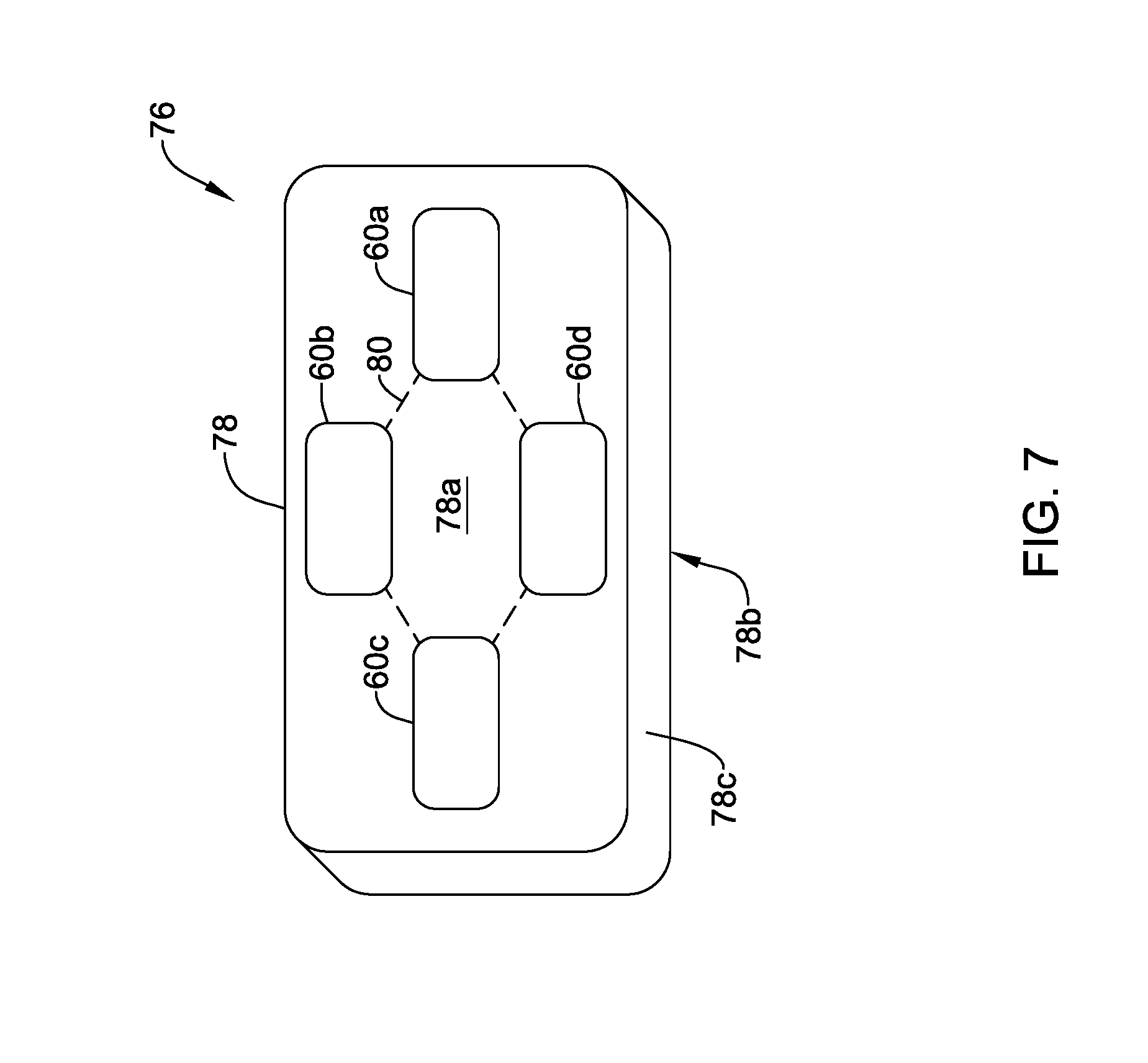
[0073] FIG. 7 is a perspective view of another illustrative bridge device 76 having a housing 78. While the housing 78 is illustrated as being rectilinear, and having an overall size perhaps the size of an average smartphone, this is merely illustrative. In some cases, the housing 78 may be circular or ovoid, and may be of any suitable dimensions. The housing 78 defines a first surface 78a and an opposing second surface 78b, with a peripheral side wall 78c extending between the first surface 78a and the second surface 78b. A total of four electrodes 60a, 60b, 60c, 60d are shown disposed on the first surface 78a. In some cases, having a plurality of electrodes 60a, 60b, 60c, 60d on the first surface 78a may provide a variety of communication vectors for communication with an IMD 12. In some cases, as illustrated, the electrodes 60a, 60b, 60c, 60d may be laid out in a kite-shape, as shown by dashed kite shape 80. In some instances, having the electrodes 60a, 60b, 60c, 60d in this "kite" configuration may provide a useful variety of communication vectors.
[0074] FIG. 8 is a perspective view of another illustrative bridge device 86 having a housing 88. While the housing 88 is illustrated as being rectilinear, and having an overall size perhaps the size of an average smartphone, this is merely illustrative. In some cases, the housing 88 may be circular or ovoid, and may be of any suitable dimensions. The housing 88 defines a first surface 88a and an opposing second surface 88b, with a peripheral side wall 88c extending between the first surface 88a and the second surface 88b. In this example, a total of four electrodes 60a, 60b, 60c, 60d are disposed on the peripheral side wall 88c. Other electrodes may be positioned on the first surface 88a and/or opposing second surface 88b, if desired. In some cases, having a plurality of electrodes 60a, 60b, 60c, 60d may provide a variety of communication and/or sense vectors. In some cases, having the electrodes 60a, 60b, 60c, 60d on the peripheral side wall 88c may facilitate contact between the electrodes 60a, 60b, 60c, 60d and the skin on the fingers/hands of the person holding the bridge device 86.
[0075] FIGS. 9 and 10 provide schematic illustrations of an example of how the remote devices described herein may be deployed. FIG. 9 shows a patient P having a bridge device 90 held against the skin of the patient P. In some cases, the bridge device 90 may be positioned on the patient, near their heart H, held in place by gravity if the patient P is prone and/or held in place by the patient's hand. In some cases, the bridge device 90 may be strapped in place. In some instances, the bridge device 90 may include an adhesive layer which holds the bridge device 90 in place, with electrodes 90a, 90b, 90c, 90d in skin contact. Including an adhesive layer or a strap may enable the patient P to be sitting or standing while the bridge device 90 is in position. In some cases, rather than being held in position on the chest of the patient P, the bridge device 90 may instead be disposed within a lanyard that the patient can wear around their neck, with the bridge device 90 hanging proximate their chest. In some cases, the bridge device 90 may be built into a wrist band, intended to be worn around the patient's wrist with the electrodes 90a, 90b, 90c, 90d in skin contact.
[0076] FIG. 10 shows a patient holding a bridge device 92 in their hands. As illustrated, this shows a view from a position looking towards the front of the patient. As can be seen, the bridge device 92 may include a four electrodes 94a, 94b, 94c, 94d that are disposed along a periphery 96 of the bridge device 92. In the example shown, several fingers of the patient's right hand RH make contact with the electrodes 94a, 94b while several fingers of the patient's left hand LH make contact with the electrodes 94c, 94d. In some cases, the back side of the bridge device 92 (not visible in FIG. 10) may include additional electrodes that can be brought into engagement with the patient's skin. These additional electrodes may be provide communication electrodes and/or additional communication vectors for communication with the IMD 12. The four electrodes 94a, 94b, 94c, 94d that are disposed along the periphery 96 may provide communication vectors for communication with the IMD 12 and/or sense electrodes/vectors for sensing one or more physiologic parameters of the patient (e.g. surface EKG).
[0077] FIG. 11 depicts an illustrative leadless cardiac pacemaker (LCP) that may be implanted into a patient and may operate to deliver appropriate therapy to the heart, such as to deliver anti-tachycardia pacing (ATP) therapy, cardiac resynchronization therapy (CRT), bradycardia therapy, and/or the like. As can be seen in FIG. 11, the LCP 100 may be a compact device with all components housed within the or directly on a housing 120. In some cases, the LCP 100 may be considered as being an example of the IMD 12 (FIG. 1). In the example shown in FIG. 11, the LCP 100 may include a communication module 102, a pulse generator module 104, an electrical sensing module 106, a mechanical sensing module 108, a processing module 110, a battery 112, and an electrode arrangement 114. The LCP 100 may also include a receive coil for receiving inductive power, and a recharge circuit for recharging the battery 112 (or capacitor) using the received inductive power. It is contemplated that the LCP 100 may include more or fewer modules, depending on the application.
[0078] The communication module 102 may be configured to communicate with devices such as sensors, other medical devices such as an SICD, another LCP, and/or the like, that are located externally to the LCP 100. Such devices may be located either external or internal to the patient's body. Irrespective of the location, external devices (i.e. external to the LCP 100 but not necessarily external to the patient's body) can communicate with the LCP 100 via communication module 102 to accomplish one or more desired functions. For example, the LCP 100 may communicate information, such as sensed electrical signals, data, instructions, messages, R-wave detection markers, etc., to an external medical device (e.g. SICD, programmer and/or bridge device 16) through the communication module 102. The external medical device may use the communicated signals, data, instructions, messages, R-wave detection markers, etc., to perform various functions, such as determining occurrences of arrhythmias, delivering electrical stimulation therapy, storing received data, and/or performing any other suitable function. The LCP 100 may additionally receive information such as signals, data, instructions and/or messages from the external medical device and/or the bridge device 16 through the communication module 102, and the LCP 100 may use the received signals, data, instructions and/or messages to perform various functions, such as determining occurrences of arrhythmias, delivering electrical stimulation therapy, storing received data, and/or performing any other suitable function. The communication module 102 may be configured to use one or more methods for communicating with external devices. For example, the communication module 102 may communicate via radiofrequency (RF) signals, inductive coupling, optical signals, acoustic signals, conducted communication signals, and/or any other signals suitable for communication.
[0079] In the example shown in FIG. 11, the pulse generator module 104 may be electrically connected to the electrode arrangement 114. In some examples, the LCP 100 may additionally include electrodes 114'. In such examples, the pulse generator 104 may also be electrically connected to the electrodes 114'. The pulse generator module 104 may be configured to generate electrical stimulation signals. For example, the pulse generator module 104 may generate and deliver electrical stimulation signals by using energy stored in the battery 112 within the LCP 100 and deliver the generated electrical stimulation signals via the electrodes 114 and/or 114'. Alternatively, or additionally, the pulse generator 104 may include one or more capacitors, and the pulse generator 104 may charge the one or more capacitors by drawing energy from the battery 112. The pulse generator 104 may then use the energy of the one or more capacitors to deliver the generated electrical stimulation signals via the electrodes 114 and/or 114'. In at least some examples, the pulse generator 104 of the LCP 100 may include switching circuitry to selectively connect one or more of the electrodes 114 and/or 114' to the pulse generator 104 in order to select which of the electrodes 114/114' (and/or other electrodes) the pulse generator 104 delivers the electrical stimulation therapy. The pulse generator module 104 may generate and deliver electrical stimulation signals with particular features or in particular sequences in order to provide one or multiple of a number of different stimulation therapies. For example, the pulse generator module 104 may be configured to generate electrical stimulation signals to provide electrical stimulation therapy to combat bradycardia, tachycardia, cardiac synchronization, bradycardia arrhythmias, tachycardia arrhythmias, fibrillation arrhythmias, cardiac synchronization arrhythmias and/or to produce any other suitable electrical stimulation therapy. Some more common electrical stimulation therapies include anti-tachycardia pacing (ATP) therapy, cardiac resynchronization therapy (CRT), and cardioversion/defibrillation therapy. In some cases, the pulse generator 104 may provide a controllable pulse energy. In some cases, the pulse generator 104 may allow the controller to control the pulse voltage, pulse width, pulse shape or morphology, and/or any other suitable pulse characteristic.
[0080] In some examples, the LCP 100 may include an electrical sensing module 106, and in some cases, a mechanical sensing module 108. The electrical sensing module 106 may be configured to sense the cardiac electrical activity of the heart. For example, the electrical sensing module 106 may be connected to the electrodes 114/114', and the electrical sensing module 106 may be configured to receive cardiac electrical signals conducted through the electrodes 114/114'. The cardiac electrical signals may represent local information from the chamber in which the LCP 100 is implanted. For instance, if the LCP 100 is implanted within a ventricle of the heart (e.g. RV, LV), cardiac electrical signals sensed by the LCP 100 through the electrodes 114/114' may represent ventricular cardiac electrical signals. In some cases, the LCP 100 may be configured to detect cardiac electrical signals from other chambers (e.g. far field), such as the P-wave from the atrium.
[0081] The mechanical sensing module 108 may include one or more sensors, such as an accelerometer, a pressure sensor, a heart sound sensor, a blood-oxygen sensor, a chemical sensor, a temperature sensor, a flow sensor and/or any other suitable sensors that are configured to measure one or more mechanical/chemical parameters of the patient. Both the electrical sensing module 106 and the mechanical sensing module 108 may be connected to a processing module 110, which may provide signals representative of the sensed mechanical parameters. Although described with respect to FIG. 11 as separate sensing modules, in some cases, the electrical sensing module 106 and the mechanical sensing module 108 may be combined into a single sensing module, as desired.
[0082] The electrodes 114/114' can be secured relative to the housing 120 but exposed to the tissue and/or blood surrounding the LCP 100. In some cases, the electrodes 114 may be generally disposed on either end of the LCP 100 and may be in electrical communication with one or more of the modules 102, 104, 106, 108, and 110. The electrodes 114/114' may be supported by the housing 120, although in some examples, the electrodes 114/114' may be connected to the housing 120 through short connecting wires such that the electrodes 114/114' are not directly secured relative to the housing 120. In examples where the LCP 100 includes one or more electrodes 114', the electrodes 114' may in some cases be disposed on the sides of the LCP 100, which may increase the number of electrodes by which the LCP 100 may sense cardiac electrical activity, deliver electrical stimulation and/or communicate with an external medical device. The electrodes 114/114' can be made up of one or more biocompatible conductive materials such as various metals or alloys that are known to be safe for implantation within a human body. In some instances, the electrodes 114/114' connected to the LCP 100 may have an insulative portion that electrically isolates the electrodes 114/114' from adjacent electrodes, the housing 120, and/or other parts of the LCP 100. In some cases, one or more of the electrodes 114/114' may be provided on a tail (not shown) that extends away from the housing 120.
[0083] The processing module 110 can be configured to control the operation of the LCP 100. For example, the processing module 110 may be configured to receive electrical signals from the electrical sensing module 106 and/or the mechanical sensing module 108. Based on the received signals, the processing module 110 may determine, for example, abnormalities in the operation of the heart H. Based on any determined abnormalities, the processing module 110 may control the pulse generator module 104 to generate and deliver electrical stimulation in accordance with one or more therapies to treat the determined abnormalities. The processing module 110 may further receive information from the communication module 102. In some examples, the processing module 110 may use such received information to help determine whether an abnormality is occurring, determine a type of abnormality, and/or to take particular action in response to the information. The processing module 110 may additionally control the communication module 102 to send/receive information to/from other devices.
[0084] In some examples, the processing module 110 may include a pre-programmed chip, such as a very-large-scale integration (VLSI) chip and/or an application specific integrated circuit (ASIC). In such embodiments, the chip may be pre-programmed with control logic in order to control the operation of the LCP 100. By using a pre-programmed chip, the processing module 110 may use less power than other programmable circuits (e.g. general purpose programmable microprocessors) while still being able to maintain basic functionality, thereby potentially increasing the battery life of the LCP 100. In other examples, the processing module 110 may include a programmable microprocessor. Such a programmable microprocessor may allow a user to modify the control logic of the LCP 100 even after implantation, thereby allowing for greater flexibility of the LCP 100 than when using a pre-programmed ASIC. In some examples, the processing module 110 may further include a memory, and the processing module 110 may store information on and read information from the memory. In other examples, the LCP 100 may include a separate memory (not shown) that is in communication with the processing module 110, such that the processing module 110 may read and write information to and from the separate memory.
[0085] The battery 112 may provide power to the LCP 100 for its operations. In some examples, the battery 112 may be a non-rechargeable lithium-based battery. In other examples, a non-rechargeable battery may be made from other suitable materials, as desired. Because the LCP 100 is an implantable device, access to the LCP 100 may be limited after implantation. Accordingly, it is desirable to have sufficient battery capacity to deliver therapy over a period of treatment such as days, weeks, months, years or even decades. In some instances, the battery 112 may a rechargeable battery, which may help increase the useable lifespan of the LCP 100. A recharge circuit may receive power from a receiving coil of the LCP 100, and use the received power to recharge the rechargeable battery. In still other examples, the battery 112 may be some other type of power source, as desired.
[0086] To implant the LCP 100 inside a patient's body, an operator (e.g., a physician, clinician, etc.), may fix the LCP 100 to the cardiac tissue of the patient's heart. To facilitate fixation, the LCP 100 may include one or more anchors 116. The anchor 116 may include any one of a number of fixation or anchoring mechanisms. For example, the anchor 116 may include one or more pins, staples, threads, screws, helix, tines, and/or the like. In some examples, although not shown, the anchor 116 may include threads on its external surface that may run along at least a partial length of the anchor 116. The threads may provide friction between the cardiac tissue and the anchor to help fix the anchor 116 within the cardiac tissue. In other examples, the anchor 116 may include other structures such as barbs, spikes, or the like to facilitate engagement with the surrounding cardiac tissue.
[0087] FIG. 12 depicts an example of another medical device (MD) 200, which may be used alone or in conjunction with the LCP 100 (FIG. 11), and may be used to detect and/or treat cardiac abnormalities. In some cases, the MD 200 may represent an implantable cardioverter defibrillator (ICD), a subcutaneous implantable cardioverter defibrillator (SICD) or a Leadless Cardiac Pacemaker (LCP) 100. In the example shown, the MD 200 may include a communication module 202, a pulse generator module 204, an electrical sensing module 206, a mechanical sensing module 208, a processing module 210, and a battery 218. Each of these modules may be similar to the modules 102, 104, 106, 108, and 110 of LCP 100. Additionally, the battery 218 may be similar to the battery 112 of the LCP 100. In some examples, however, the MD 200 may have a larger volume within the housing 220. In such examples, the MD 200 may include a larger battery and/or a larger processing module 210 capable of handling more complex operations than the processing module 110 of the LCP 100.
[0088] While it is contemplated that the MD 200 may be another leadless device such as shown in FIG. 11, in some instances the MD 200 may include leads such as leads 212. The leads 212 may include electrical wires that conduct electrical signals between the electrodes 214 and one or more modules located within the housing 220. In some cases, the leads 212 may be connected to and extend away from the housing 220 of the MD 200. In some examples, the leads 212 are implanted on, within, or adjacent to a heart of a patient. The leads 212 may contain one or more electrodes 214 positioned at various locations on the leads 212, and in some cases at various distances from the housing 220. Some leads 212 may only include a single electrode 214, while other leads 212 may include multiple electrodes 214. Generally, the electrodes 214 are positioned on the leads 212 such that when the leads 212 are implanted within the patient, one or more of the electrodes 214 are positioned to perform a desired function. In some cases, the one or more of the electrodes 214 may be in contact with the patient's cardiac tissue. In some cases, the one or more of the electrodes 214 may be positioned subcutaneously and outside of the patient's heart. In some cases, the electrodes 214 may conduct intrinsically generated electrical signals to the leads 212, e.g. signals representative of intrinsic cardiac electrical activity. The leads 212 may, in turn, conduct the received electrical signals to one or more of the modules 202, 204, 206, and 208 of the MD 200. In some cases, the MD 200 may generate electrical stimulation signals, and the leads 212 may conduct the generated electrical stimulation signals to the electrodes 214. The electrodes 214 may then conduct the electrical signals and delivery the signals to the patient's heart (either directly or indirectly). In some cases, a transmit coil may be supported by the lead, such at a location along the length of the lead that is near the receive coil of a remote implantable medical device.
[0089] The mechanical sensing module 208, as with the mechanical sensing module 108, may contain or be electrically connected to one or more sensors, such as accelerometers, acoustic sensors, blood pressure sensors, heart sound sensors, blood-oxygen sensors, and/or other sensors which are configured to measure one or more mechanical/chemical parameters of the heart and/or patient. In some examples, one or more of the sensors may be located on the leads 212, but this is not required. In some examples, one or more of the sensors may be located in the housing 220.
[0090] While not required, in some examples, the MD 200 may be an implantable medical device. In such examples, the housing 220 of the MD 200 may be implanted in, for example, a transthoracic region of the patient. The housing 220 may generally include any of a number of known materials that are safe for implantation in a human body and may, when implanted, hermetically seal the various components of the MD 200 from fluids and tissues of the patient's body.
[0091] In some cases, the MD 200 may be an implantable cardiac pacemaker (ICP). In this example, the MD 200 may have one or more leads, for example the leads 212, which are implanted on or within the patient's heart. The one or more leads 212 may include one or more electrodes 214 that are in contact with cardiac tissue and/or blood of the patient's heart. The MD 200 may be configured to sense intrinsically generated cardiac electrical signals and determine, for example, one or more cardiac arrhythmias based on analysis of the sensed signals. The MD 200 may be configured to deliver CRT, ATP therapy, bradycardia therapy, and/or other therapy types via the leads 212 implanted within the heart. In some examples, the MD 200 may additionally be configured provide defibrillation therapy.
[0092] In some instances, the MD 200 may be an implantable cardioverter-defibrillator (ICD) with the ability to pace. In such examples, the MD 200 may include one or more leads implanted within a patient's heart. The MD 200 may also be configured to sense cardiac electrical signals, determine occurrences of tachyarrhythmias based on the sensed signals, and may be configured to deliver defibrillation therapy in response to determining an occurrence of a tachyarrhythmia. In other examples, the MD 200 may be a subcutaneous implantable cardioverter-defibrillator (S-ICD) with the ability to pace. In examples where the MD 200 is an S-ICD, one of the leads 212 may be a subcutaneously implanted lead. In some instances, the lead(s) may have one or more electrodes that are placed subcutaneously and outside of the chest cavity. In other examples, the lead(s) may have one or more electrodes that are placed inside of the chest cavity, such as just interior of the sternum but outside of the heart H.
[0093] In some cases, the MD 200 may not include the pulse generator module 204, and may simply be an implantable diagnostic sensor medical device that is configured to capture and provide diagnostic data, sometimes to the external device 14 via the bridge device 16.
[0094] It should be understood that this disclosure is, in many respects, only illustrative. Changes may be made in details, particularly in matters of shape, size, and arrangement of steps without exceeding the scope of the disclosure. This may include, to the extent that it is appropriate, the use of any of the features of one example embodiment being used in other embodiments.
* * * * *
D00000
D00001
D00002
D00003
D00004
D00005
D00006
D00007
D00008
D00009
D00010
D00011
D00012

XML
uspto.report is an independent third-party trademark research tool that is not affiliated, endorsed, or sponsored by the United States Patent and Trademark Office (USPTO) or any other governmental organization. The information provided by uspto.report is based on publicly available data at the time of writing and is intended for informational purposes only.
While we strive to provide accurate and up-to-date information, we do not guarantee the accuracy, completeness, reliability, or suitability of the information displayed on this site. The use of this site is at your own risk. Any reliance you place on such information is therefore strictly at your own risk.
All official trademark data, including owner information, should be verified by visiting the official USPTO website at www.uspto.gov. This site is not intended to replace professional legal advice and should not be used as a substitute for consulting with a legal professional who is knowledgeable about trademark law.