Stationary Massage Device, System And Methods For Soft Tissue Strain Release
Su; Jason T.
U.S. patent application number 16/298194 was filed with the patent office on 2019-07-04 for stationary massage device, system and methods for soft tissue strain release. The applicant listed for this patent is Jason T. Su. Invention is credited to Jason T. Su.
| Application Number | 20190201272 16/298194 |
| Document ID | / |
| Family ID | 65137928 |
| Filed Date | 2019-07-04 |


View All Diagrams
| United States Patent Application | 20190201272 |
| Kind Code | A1 |
| Su; Jason T. | July 4, 2019 |
STATIONARY MASSAGE DEVICE, SYSTEM AND METHODS FOR SOFT TISSUE STRAIN RELEASE
Abstract
A stationary massage device, system and corresponding methods are used for self-administrated or assisted soft tissue strain release (including trigger point therapy, strain-and-counterstrain therapy and neuromuscular release). The massage device comprises a body, wherein the body may include branches, each having flat surfaces, edges, ridges or corners. The surfaces, edges and ridges may be pushed along the myofilament direction of the soft tissues to produce pressing, rubbing, stretching and pulling actions on the soft tissues as stripping massages. The system can be configured to form different geometric shapes, and made of different materials of different firmness. The system can be further configured to perform unheated, or heated massages; and cooling treatments. In addition to being used alone, the system can be mounted on a piece of wall, a standing frame, furniture or a garment.
| Inventors: | Su; Jason T.; (CUPERTINO, CA) | ||||||||||
| Applicant: |
|
||||||||||
|---|---|---|---|---|---|---|---|---|---|---|---|
| Family ID: | 65137928 | ||||||||||
| Appl. No.: | 16/298194 | ||||||||||
| Filed: | March 11, 2019 |
Related U.S. Patent Documents
| Application Number | Filing Date | Patent Number | ||
|---|---|---|---|---|
| 15658413 | Jul 25, 2017 | |||
| 16298194 | ||||
| Current U.S. Class: | 1/1 |
| Current CPC Class: | A61H 7/00 20130101; A61H 7/001 20130101; A61H 2201/0228 20130101; A61H 2201/1619 20130101; A61F 2007/0228 20130101; A61F 7/02 20130101; A61F 7/007 20130101; A61H 2201/0149 20130101; A61H 2201/0292 20130101; A61F 7/03 20130101; A61H 2201/1692 20130101; A61H 7/002 20130101; A61F 7/0097 20130101; A61H 2201/0278 20130101; A61H 2201/1671 20130101; A61H 2201/165 20130101; A61H 2201/0138 20130101; A61F 2007/0242 20130101; A61F 2007/0233 20130101; A61H 7/003 20130101; A61F 2007/0223 20130101; A61F 2007/0052 20130101; A61H 2201/0214 20130101; A61H 2201/0207 20130101; A61H 1/02 20130101; A61H 2201/1623 20130101; A61F 7/08 20130101; A61F 2007/0231 20130101; A61F 2007/0207 20130101; A61H 1/006 20130101; A61H 2201/0126 20130101; A61H 2201/169 20130101 |
| International Class: | A61H 1/02 20060101 A61H001/02; A61F 7/00 20060101 A61F007/00; A61F 7/03 20060101 A61F007/03; A61H 7/00 20060101 A61H007/00 |
Claims
1. A massage system comprising a standing mounting frame comprising a first standing member; a second standing member; one or more connection members connecting the first standing member to the second standing member; and one or more mounting bars attached to the first standing member and the second standing member; and a plurality of massage devices mounted on the one or more mounting bars of the standing mounting frame.
2. The massage system of claim 1, wherein the first standing member comprises a first floor element extending along a first direction; and a first post element attached to the first floor element, the first post element being extending along a second direction perpendicular to the first direction; and wherein the second standing member comprises a second floor element extending along the first direction; and a second post element attached to the second floor element, the second post element being extending along the second direction.
3. The massage system of claim 2, wherein the one or more connection members comprise a first connection member; and a second connection member; wherein the one or more connection members extend along a third direction perpendicular to the first direction and the second direction; and wherein the second connection member is closer to the first floor element than the first connection member.
4. The massage system of claim 3, wherein the one or more mounting bars comprises a first mounting bar; and a second mounting bar; wherein the one or more mounting bars extend along the third direction; and wherein the second mounting bar is closer to the first floor element than the first mounting bar.
5. The massage system of claim 4, wherein the plurality of massage devices comprise a first massage device directly attached to the first mounting bar; a second massage device directly attached to the first mounting bar; a third massage device directly attached to the second mounting bar; and a fourth massage device directly attached to the second mounting bar; wherein the plurality of massage devices extend along the first direction.
6. The massage system of claim 5, wherein the massage system is characterized by a first condition in which a distance between the first massage device and the second massage device is larger than a distance between the third massage device and the fourth massage device; and a second condition in which the distance between the first massage device and the second massage device is smaller than the distance between the third massage device and the fourth massage device.
7. The massage system of claim 6, wherein the massage system is further characterized by the first condition in which the third massage device and the fourth massage device are configured to be sit by a user; and the second condition in which the third massage device and the fourth massage device are configured to be contacted by a first thigh and a second thigh of the user respectively.
8. The massage system of claim 7, wherein a side massage device is directly attached to the first post element of the first standing member of the standing mounting frame and wherein the side massage device extends along the first direction.
9. The massage system of claim 8, wherein the massage system is further characterized by the second condition in which a space between the third massage device and the side massage device is configured to receive a leg of the user.
10. The massage system of claim 7, wherein a top massage device is directly attached to the first mounting bar and wherein the top massage device extends along the first direction.
11. The massage system of claim 10, wherein the massage system is further characterized by the second condition in which a space between the first massage device and the top massage device is configured to receive an arm of the user.
12. The massage system of claim 7 further comprising a first supporting massage device directly attached to the first mounting bar; a second supporting massage device directly attached to the second mounting bar; a third supporting massage device directly attached to the third massage device and the fourth massage device; and a fourth supporting massage device directly attached to the third massage device.
13. The massage system of claim 12, wherein the massage system is further characterized by the first condition in which the first supporting massage device is configured to be contacted by a neck of the user; the second supporting massage device is configured to be contacted by a back of the user; the third supporting massage device is configured to be contacted by a buttock of the user; and the fourth supporting massage device is configured to be contacted by a thigh of the user.
14. The massage system of claim 5 further comprising a supporting massage device directly attached to the first mounting bar; wherein the supporting massage device extends along the second direction; and wherein the supporting massage device is configured to be contacted by a back of a user.
Description
CROSS-REFERENCE TO RELATED APPLICATIONS
[0001] This patent application is a Divisional Application of a pending U.S. patent application Ser. No. 15/658,413 filed on Jul. 25, 2017. The Disclosure made in U.S. patent application Ser. No. 15/658,413 is hereby incorporated by reference.
FIELD OF THE INVENTION
[0002] The present invention relates to soft tissue strain release (including trigger point therapy, strain-and-counterstrain therapy and neuromuscular release) therapy devices, systems and methods. More particularly, the present invention relates to soft tissue strain release therapy which emphasizes stripping and passive stretching.
BACKGROUND
[0003] Soft tissue strain release (including trigger point, strain-and-counterstrain and neuromuscular release) therapy is a method commonly used by physical and massage therapists, osteopaths and chiropractors to treat soft tissue relate pains, and to restore physical healthiness and functions of a patient. A properly design soft tissue strain release device or system can facilitate the practice of these health care professional, and reduce the risk of their work injuries. It can also enable the patients to perform self-administrated therapies away from a clinic, and increase the frequency of the intervention as they are often time required.
[0004] Conventionally available devices for this application herein described are canes, balls, rollers and hand-held or mounted probes. They generally make contact with the body in two shapes: ball or cylinder. The rolling or probing action mainly generates forces perpendicular to the skin surface, which are called normal forces. They generate relatively low amount of forces lateral to the skin surface, which are called shear forces, compared to stripping massage as a massage therapist does with his or her hands. Therefore, the conventional massage devices don't achieve the full effectiveness of the hand massage that involves stripping actions. A massage device such as in U.S. Pat. No. 5,643,182 demonstrates a cylinder-shaped massager that rolls on the skin. Massage devices such as in U.S. Pat. No. 8,932,322 and US20130085426 demonstrate ball-shaped massagers that probe at trigger points.
[0005] In order to generate sufficient shear forces to achieve the full effectiveness of a massage therapy, the massage device must possess the following capabilities: 1) sitting still against the movement of the user's body, 2) distributes the forces in strip shape (long and narrow), moving in parallel (0 degree) along or at a small angle to the direction of the myofilaments.
[0006] Ideally, this massage device should still have pointy parts available to probe trigger points alone. It should be able to fit various locations of the body, too, stripping and probing alike. It should further address the needs of a massage with heating and cooling treatments.
SUMMARY OF THE INVENTION
[0007] Disclosed herein is the present invention "Stationary Massage Device, System and Methods for Soft Tissue Strain Release". The object of the present invention is to provide an apparatus, a system, and methods that can facilitate self-administrated as well as assisted stripping and probing massage therapies.
[0008] It is yet another objective of the invention to provide a massage device, a system, and methods which temperature can be raised or lowered to meet the requirements of certain treatments.
[0009] In one embodiment, the soft tissue strain release system comprises a tool. The tool comprises a bar-shaped body, wherein the body includes multiple surfaces. The surfaces form edges, ridges or corners: the edges defined by the joint of two surfaces; the ridges defined by a strip of flat narrower surface rising above some of other surfaces, or sitting on the top of some of its surrounding surfaces when the body lies at certain positions; and the corners defined by pointy parts that may be formed by the joint of three or more surfaces.
[0010] In another embodiment, the soft tissue strain release system comprises a tool. The tool comprises a body, wherein the body includes one or multiple sections connected together, each section constituting an embodiment of the hereinbefore mentioned embodiment.
[0011] In yet another embodiment, the soft tissue strain release system comprises a tool. The tool comprises a body, wherein the body includes one or multiple of the embodiments mentioned hereinbefore, and a heating source surrounding around or embedded inside the body.
[0012] The detailed technology and preferred embodiments implemented for the subject invention are described in the following paragraphs accompanying the appended drawings for people skilled in this field to well appreciate the features of the claimed invention. It is understood that the features mentioned hereinbefore and those to be commented on hereinafter may be used not only in the specified combinations, but also in other combinations or in isolation, without departing from the scope of the present invention.
Advantageous Effects of the Invention
[0013] The present invention "Stationary Massage Device, System and Methods for Soft Tissue Strain Release" has the following main advantageous effects: 1) having a flat and branched surface to form a stable bottom, and allowing the massage system to have a good grip on the surface where the massage system sits, producing the stability for shear force generation a stripping massage requires; 2) having the flexibility of doing any combination of stripping and probing massages through the combination of the edges and corners made in different orientations in one single system; 3) simply by rotating the system and aligning it at different angles with respect to his or her body, the user being able to press two trigger points separated by various distances; 4) having different geometric shapes formed by different ends of different sections permitting the users to fit said system in different locations of their bodies; 4) each branch or section of the system serving any of the following purposes: a contact component, a handle and an anchor.
BRIEF DESCRIPTION OF THE DRAWINGS
[0014] FIG. 1 is a perspective view of a stationary message device for soft tissue strain release according to certain embodiments.
[0015] FIG. 2 is a top view of a stationary message device for soft tissue strain release according to certain embodiments.
[0016] FIG. 3 is a perspective view of a stationary message device for soft tissue strain release according to certain embodiments.
[0017] FIG. 4 is a perspective view of a stationary message device for soft tissue strain release according to certain embodiments.
[0018] FIG. 5 is a horizontal cross section view of a stationary message device for soft tissue strain release according to certain embodiments.
[0019] FIG. 6 is a horizontal cross section view of a stationary message device for soft tissue strain release according to certain embodiments.
[0020] FIG. 7 is a perspective view of a stationary message device for soft tissue strain release according to certain embodiments.
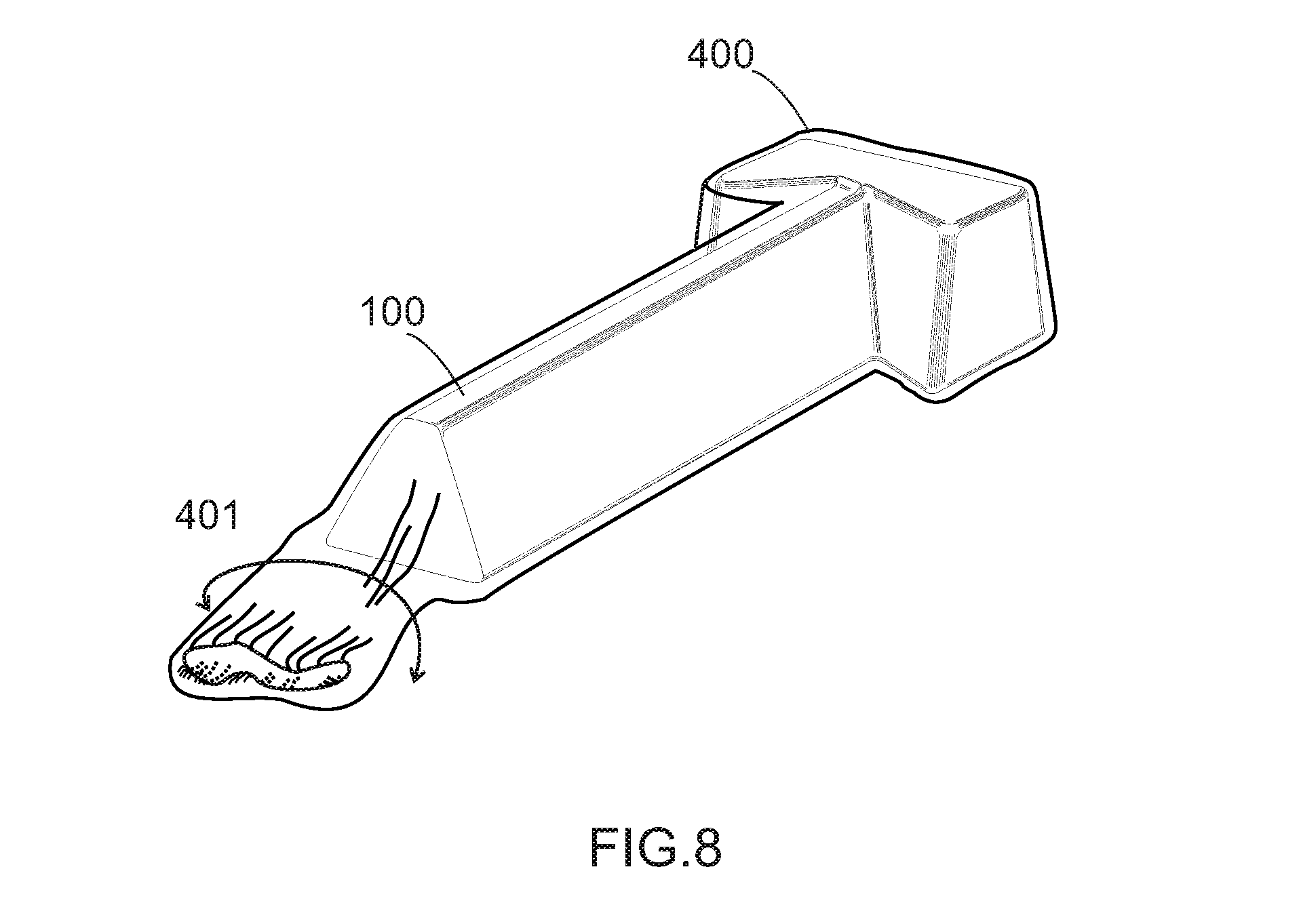
[0021] FIG. 8 is a perspective view of a stationary message device for soft tissue strain release according to certain embodiments.
[0022] FIG. 9 is a perspective view of a stationary message device for soft tissue strain release according to certain embodiments.
[0023] FIG. 10 is a perspective view of a stationary message device for soft tissue strain release according to certain embodiments.
[0024] FIG. 11 is a perspective view of a stationary message device for soft tissue strain release according to certain embodiments.
[0025] FIG. 12 is a perspective view of a stationary message device for soft tissue strain release according to certain embodiments.
[0026] FIG. 13-34 are illustrations of the use of a stationary message device for soft tissue strain release according to certain embodiments.
DETAILED DESCRIPTION
[0027] In the following descriptions, the present invention will be explained with reference to example embodiments thereof. However, these example embodiments are not intended to limit the present invention to any specific example, embodiment, environment, applications or particular implementations described in these example embodiments. Therefore, description of these embodiments is only for purpose of illustration rather than to limit the present invention. It should be appreciated that, in the following embodiments and the attached drawings, elements unrelated to the present invention are omitted from depiction; and dimensional relationships among individual elements in the attached drawings are illustrated only for ease of understanding, but not to limit the actual scale.
[0028] Referring first to FIG. 1-10, various embodiments of the present invention of stationary massage device for soft tissue strain release are shown. Referring to FIG. 1, the device comprises a body 100 including multiple surfaces 201-208, edges 211-216, and corners 221-226. The surfaces 201-208 can be of any shape, preferably a polygon such as a trapezoid, a rectangle, a triangle or a square. The edges 211-216 formed at the junction of two of the surfaces 201-208, can have curvatures of any radius, small radius for deeper stripping massage actions, and large radius for more superficial rubbing actions. The corners 221-226 are formed where 3 or more of the surfaces 201-208 join together. The corners 221-226 may have curvatures of any radius. These examples of the embodiments of the present invention are provided to facilitate the description and understanding, but not to limit the choices of implementation.
[0029] Referring to FIG. 1-4, two bodies 100 and 101 with different proportions of the top surfaces 208 and the bottom surfaces 203 are illustrated. As demonstrated, the surfaces 201-208 and edges 211-216 can be made of different proportions without departing from the scope of the invention. The body of the massage device may comprise a single section or multiple sections connected to each other. Each of the sections thereof can be made straight or curved. As illustrated in FIG. 1-2, the body of the device includes three connected sections that form together a T-shaped cross section on its horizontal planes.
[0030] FIGS. 5 and 6 illustrate embodiments having different top views, one having T shape, and the other F shape. Comprising different counts and shapes of said sections allows the user to reach different locations of his or her body.
[0031] Referring to FIG. 7, an embodiment of the present invention comprises body 104 that has a plurality of smaller components 301-310, each having pegs 311 and holes 312 to hold each other together when assembled. Components 301-310 can be arranged in any style to scale up or down the dimensions of any surface, and any edge of body 104. The sizes, the shapes and the numbers of components 301-310, and of their pegs 311 and holes 312 can be varied without departing from the scope of the invention. The methods of bonding components 301-310 is not limited to pegs 311 and holes 312 as exemplified in FIG. 7. There are presented to facilitate the illustration of the present invention, and can be replaced with other methods such as screws, Velcro or glue without departing from the scope of the invention.
[0032] The bodies 100-104 shown in FIG. 1-7 can be made of any type of natural or manmade materials, such as wood, glass, metal, plastic, rubber, and ceramic, or of a combination of two or more of them. Referring to FIG. 8, an embodiment 105 of the present invention comprising two different materials is shown. Body 105 includes body 100 made of a hard material, and wrapper 400 made of soft fabric. Wrapper 400 permits the user to change the firmness and the texture of the contacts, and, in turn, the depth of the pressing and the friction of rubbing, respectively. A tail 401 of wrapper 400 may be made as an extension to facilitate the handling and the anchoring during application.
[0033] Referring to FIGS. 9 and 10, wrapper 500 for heated massage is illustrated. In this embodiment, body 100 is wrapped by a heating wrapper 500. Heating wrapper 500 comprises pockets 501 that contain rice grains, beans or any material with practically high heat capacity that can be heated up by microwave, thereafter, hold the heat, and gradually release the heat over a reasonably long period of time. The wrapper 500 may include, but not limited to, a securing method Velcro tape 502.
[0034] Referring to FIGS. 11 and 12, another heating method is illustrated. In this embodiment, body 100 is wrapped by electrically heated blanket wrapper 600.
[0035] FIG. 13-34 demonstrate the use of one of the embodiments of the present invention of stationary massage devices for soft tissue strain release. Referring to FIG. 17-24, the user identifies the zones needed to be treated, lying face up if the zones are found on the back side, or lying face down if the zones are on the frontal side. The user thereafter puts device 100 under his or her body, and presses the soft tissues against the edges and/or corners of device 100 with his or her body weight and movement. Stationary massage device 100 sits still, stretching, rubbing or probing the soft tissues as the user moves his or her body. With some adjustment on the location and the angle of device 100 after it is placed, the user finds the optimal position to perform the massage. Simultaneous stripping, rubbing and probing at various locations in proximity are performed that yields the effects most similar to massages by the hands of a physical therapist or a masseuse. This is what a conventional cylinder-shaped roller, or a spherical or pointy probe massage device cannot do.
[0036] Referring to FIG. 25, an embodiment of stationary massage device 100 including components hooks 701 and strings is 702 is illustrated. The securing components such as 701 and 702 enable the device to be mounted on furniture. In this example, device 100 is mounted on a chair. This system can be very useful in reducing the risk of repetitive stress (strain) injury at a work place when it is made commonly available, and its self-administrated massage as a common practice is promoted.
[0037] Referring to FIG. 26, an embodiment of stationary massage device 108 is shaped and sized in such a way that the user may recline in it as a chair or a couch. Having his or her strained soft tissues in the back or in the shoulder areas, the user may sit with his or her back pressed and moved against one of the edges of device 108. Similarly, the user may lie facing downward with his or her chest leaning toward the device to treat the strained soft tissues in the chest or in abdominal areas. System including device 108 or a furniture comprising device 108 is very useful at a rehabilitation center, a nursing home, or even a work place where regular soft-tissue-strain-releasing exercise is a key component of maintaining or restoring the healthiness of its member.
[0038] Referring to FIG. 27-31, a single or multiple stationary massage devices 100 are mounted on a standing mounting frame 801-805. They provide further stability and flexibility. The mounting positions of stationary massage devices 100 can be configured differently as shown. The flexibility permits the user to access certain hard-to-reach areas that can be only exposed when the user is sitting or reclining in some unique positions the standing frame enables him or her to take. However, the systems with mounting frames 801-804 required more space, and aren't as easy to carry around as a portable counterpart. Therefore, they are suitable for clinic applications where many users may visit and share the equipment. They are also very suitable for fitness centers, sports clubs, pharmacy, shopping centers or places like these where a larger space and public access are available, and the exercises of early prevention of the sports-related injuries are beneficial.
[0039] FIG. 28 shows a massage system 802 in examples of the present disclosure. The massage system 802 comprises a standing mounting frame 2820 and a plurality of massage devices 2860. The standing mounting frame 2820 comprises a first standing member 2822, a second standing member 2824, one or more connection members 2840 connecting the first standing member 2822 to the second standing member 2824, and one or more mounting bars 2850 attached to the first standing member 2822 and the second standing member 2824. The plurality of massage devices 2860 are mounted on the one or more mounting bars 2850 of the standing mounting frame 2820.
[0040] The first standing member 2822 comprises a first floor element 2811 extending along X direction, and a first post element 2813 attached to the first floor element 2811. The first post element 2813 extends along Z direction. The second standing member 2824 comprises a second floor element 2831 extending along X direction, and a second post element 2833 attached to the second floor element 2831. The second post element 2833 extends along Z direction.
[0041] The one or more connection members 2840 comprise a first connection member 2842, and a second connection member 2844. The one or more connection members 2840 extend along Y direction. The second connection member 2844 is closer to the first floor element 2811 than the first connection member 2842.
[0042] The one or more mounting bars 2850 comprises a first mounting bar 2852, and a second mounting bar 2854. The one or more mounting bars 2850 extend along Y direction. The second mounting bar 2854 is closer to the first floor element 2811 than the first mounting bar 2852.
[0043] The plurality of massage devices 2860 comprise a first massage device 2862 directly attached to the first mounting bar 2852, a second massage device 2864 directly attached to the first mounting bar 2852, a third massage device 2866 directly attached to the second mounting bar 2854, and a fourth massage device 2868 directly attached to the second mounting bar 2854. The plurality of massage devices 2860 extend along X direction.
[0044] The massage system is characterized by a first condition (see FIG. 28) and a second condition (see FIG. 31). In the first condition (see FIG. 28), a distance between the first massage device 2862 and the second massage device 2864 is larger than a distance between the third massage device 2866 and the fourth massage device 2868. The user sits on the third massage device 2866 and the fourth massage device 2868. In the second condition (see FIG. 31), the distance between the first massage device 3162 and the second massage device 3164 is smaller than the distance between the third massage device 3166 and the fourth massage device 3168. The first thigh of the user contacts the third massage device 3166. The second thigh of the user contacts the fourth massage device 3168. A side massage device 3190 is directly attached to the first post element 2813 of the first standing member 2822 of the standing mounting frame 2820. The side massage device 3190 extends along X direction. A space 3199 between the third massage device 3166 and the side massage device 3190 is configured to receive a leg of the user. Still in the second condition (see FIG. 30), a top massage device 3097 is directly attached to the first mounting bar 2852. The top massage device 3097 extends along X direction. A space 3081 between the first massage device 2862 and the top massage device 3097 is configured to receive an arm of the user.
[0045] Referring now to FIG. 29, the massage system further comprises a first supporting massage device 2952 directly attached to the first mounting bar 2852, a second supporting massage device 2954 directly attached to the second mounting bar 2854, a third supporting massage device 2956 directly attached to the third massage device 2866 and the fourth massage device 2868, and a fourth supporting massage device 2958 directly attached to the third massage device 2866. A neck of the user contacts the first supporting massage device 2952. A back of the user contacts the second supporting massage device 2954. A buttock of the user contacts the third supporting massage device 2956. A thigh of the user contacts the fourth supporting massage device 2958.
[0046] Referring now to FIG. 27, the massage system further comprises a supporting massage device 2776 directly attached to the first mounting bar 2852. The supporting massage device 2776 extends along Z direction. A back of a user contacts the supporting massage device 2776.
[0047] Referring to FIG. 32-33, an embodiment with Velcro garment 901 comprising massage system 100 is shown. Referring to FIG. 34, similarly, an embodiment with strap or belt massage wear 902 comprising system 100 is shown. They provide further flexibilities of the use of the current invention.
[0048] The above disclosure is related to the detailed technical contents and inventive features thereof. People skilled in this field may proceed with a variety of modifications and replacements based on the disclosures and suggestions of the invention as described without departing from the characteristics thereof. Although such modifications and replacements may not be fully disclosed in the above descriptions, the following claims will further cover possible variations within the scope of the invention.
* * * * *
D00000
D00001
D00002
D00003
D00004
D00005
D00006
D00007
D00008
D00009
D00010
D00011
D00012

D00013

D00014

D00015

D00016

D00017

D00018

XML
uspto.report is an independent third-party trademark research tool that is not affiliated, endorsed, or sponsored by the United States Patent and Trademark Office (USPTO) or any other governmental organization. The information provided by uspto.report is based on publicly available data at the time of writing and is intended for informational purposes only.
While we strive to provide accurate and up-to-date information, we do not guarantee the accuracy, completeness, reliability, or suitability of the information displayed on this site. The use of this site is at your own risk. Any reliance you place on such information is therefore strictly at your own risk.
All official trademark data, including owner information, should be verified by visiting the official USPTO website at www.uspto.gov. This site is not intended to replace professional legal advice and should not be used as a substitute for consulting with a legal professional who is knowledgeable about trademark law.