Surgical Hub Spatial Awareness To Determine Devices In Operating Theater
Shelton, IV; Frederick E. ; et al.
U.S. patent application number 15/940671 was filed with the patent office on 2019-07-04 for surgical hub spatial awareness to determine devices in operating theater. The applicant listed for this patent is Ethicon LLC. Invention is credited to Daniel E. Alesi, Jason L. Harris, Frederick E. Shelton, IV, David C. Yates.
| Application Number | 20190201104 15/940671 |
| Document ID | / |
| Family ID | 63209683 |
| Filed Date | 2019-07-04 |


View All Diagrams
| United States Patent Application | 20190201104 |
| Kind Code | A1 |
| Shelton, IV; Frederick E. ; et al. | July 4, 2019 |
SURGICAL HUB SPATIAL AWARENESS TO DETERMINE DEVICES IN OPERATING THEATER
Abstract
A surgical hub is disclosed. The surgical hub includes a processor and a memory coupled to the processor. The memory stores instructions executable by the processor to receive first image data from a first image sensor, the first image data represents a first field of view, receive second image data from a second image sensor, wherein the second image data represents a second field of view, and display, on a display coupled to the processor, a first image rendered from the first image data corresponding to the first field of view and a second image rendered from the second image data corresponding to the second field of view.
| Inventors: | Shelton, IV; Frederick E.; (Hillsboro, OH) ; Yates; David C.; (West Chester, OH) ; Harris; Jason L.; (Lebanon, OH) ; Alesi; Daniel E.; (Lebanon, OH) | ||||||||||
| Applicant: |
|
||||||||||
|---|---|---|---|---|---|---|---|---|---|---|---|
| Family ID: | 63209683 | ||||||||||
| Appl. No.: | 15/940671 | ||||||||||
| Filed: | March 29, 2018 |
Related U.S. Patent Documents
| Application Number | Filing Date | Patent Number | ||
|---|---|---|---|---|
| 62649309 | Mar 28, 2018 | |||
| 62611341 | Dec 28, 2017 | |||
| 62611340 | Dec 28, 2017 | |||
| 62611339 | Dec 28, 2017 | |||
| Current U.S. Class: | 1/1 |
| Current CPC Class: | A61B 2090/3966 20160201; A61B 2017/00119 20130101; A61B 1/00009 20130101; A61B 1/00048 20130101; G16H 30/40 20180101; A61B 34/25 20160201; A61B 1/05 20130101; A61B 2017/00026 20130101; A61B 2034/2059 20160201; G16H 80/00 20180101; A61B 2017/00084 20130101; A61B 2090/0808 20160201; A61B 2217/007 20130101; A61B 2034/2063 20160201; A61B 2017/00061 20130101; A61B 2017/00809 20130101; A61B 2017/00199 20130101; A61B 2017/2927 20130101; A61B 17/02 20130101; A61B 2090/066 20160201; A61B 2017/00734 20130101; A61B 2017/00464 20130101; A61B 2217/005 20130101; A61B 2034/2057 20160201; A61B 18/20 20130101; A61B 2090/0811 20160201; A61B 1/00055 20130101; A61B 90/30 20160201; G16H 40/60 20180101; A61B 2090/378 20160201; G16H 40/67 20180101; A61B 2090/309 20160201; A61B 2017/00473 20130101; A61B 90/37 20160201; G16H 40/20 20180101; A61B 17/1155 20130101; A61B 1/00039 20130101; A61B 2017/00398 20130101; A61B 2034/254 20160201; G16H 20/40 20180101; A61B 18/12 20130101; A61B 34/20 20160201; A61B 1/0005 20130101; A61B 34/30 20160201; A61B 17/07207 20130101; A61B 90/361 20160201; A61B 2090/065 20160201; A61B 2090/372 20160201; A61B 2090/502 20160201; A61B 2017/00017 20130101; A61B 90/98 20160201; A61B 2218/008 20130101; A61B 1/00011 20130101; A61B 2017/00203 20130101; A61B 2017/00022 20130101; A61B 2017/00221 20130101; A61B 2090/0803 20160201; A61B 2017/00039 20130101; A61B 2034/2048 20160201 |
| International Class: | A61B 34/20 20060101 A61B034/20; A61B 90/00 20060101 A61B090/00; A61B 1/00 20060101 A61B001/00; G16H 40/60 20060101 G16H040/60 |
Claims
1. A surgical hub, comprising: a processor; and a memory coupled to the processor, the memory storing instructions executable by the processor to: receive first image data from a first image sensor, wherein the first image data represents a first field of view; receive second image data from a second image sensor, wherein the second image data represents a second field of view; and display, on a display coupled to the processor, a first image rendered from the first image data corresponding to the first field of view and a second image rendered from the second image data corresponding to the second field of view.
2. The surgical hub of claim 1, wherein the first field of view is a narrow angle field of view.
3. The surgical hub of claim 1, wherein the first field of view is a wide angle field of view.
4. The surgical hub of claim 1, wherein the memory stores instructions executable by the processor to augment the first image with the second image on the display.
5. The surgical hub of claim 1, wherein the memory stores instructions executable by the processor to fuse the first image and the second image into a third image and display a fused image on the display.
6. The surgical hub of claim 1, wherein the fused image data comprises status information associated with a surgical device, an image data integration landmark to interlock a plurality of images, and at least one guidance parameter.
7. The surgical hub of claim 1, wherein the first image sensor is the same as the second image sensor and wherein the first image data is captured as a first time by the first image sensor and the second image data is captured at a second time by the first image sensor.
8. The surgical hub of claim 1, wherein the memory stores instructions executable by the processor to: receive third image data from a third image sensor, wherein the third image data represents a third field of view; generate composite image data comprising the second and third image data; display the first image in a first window of the display, wherein the first image corresponds to the first image data; and display a third image in a second window of the display, wherein the third image corresponds to the composite image data.
9. The surgical hub of claim 1, wherein the memory stores instructions executable by the processor to: receive third image data from a third image sensor, wherein the third image data represents a third field of view; fuse the second and third image data to generate fused image data; display the first image in a first window of the display, wherein the first image corresponds to the first image data; and display a third image in a second window of the display, wherein the third image corresponds to the fused image data.
10. A surgical hub, comprising: a processor; and a memory coupled to the processor, the memory storing instructions executable by the processor to: detect a surgical device connection to the surgical hub; transmit a control signal to the detected surgical device to transmit to the surgical hub surgical parameter data associated with the detected surgical device; receive the surgical parameter data from the detected surgical device; receive image data from an image sensor; and display, on a display coupled to the surgical hub, an image rendered based on the image data received from the image sensor in conjunction with the surgical parameter data received from the surgical device.
11. The surgical hub of claim 10, wherein the surgical device comprises a local display that is separate from the display coupled to the surgical hub.
12. The surgical hub of claim 11, wherein the surgical device connected to the surgical hub is configured to reconfigure the local display to present information that is different from information presented when the surgical device is not connected to the surgical hub.
13. The surgical hub of claim 11, wherein a portion of information displayed on the local display is displayed on the display coupled to the surgical hub.
14. The surgical hub of claim 11, wherein information displayed on the display coupled to the surgical hub is mirrored on the local display of the surgical device.
15. A surgical hub, comprising: a control circuit configured to: detect a surgical device connection to the surgical hub; transmit a control signal to the detected surgical device to transmit to the surgical hub surgical parameter data associated with the detected surgical device; receive the surgical parameter data from the detected surgical device; receive image data from an image sensor; and display, on a display coupled to the surgical hub, an image received from the image sensor in conjunction with the surgical parameter data received from the surgical device.
16. The surgical hub of claim 15, wherein the surgical device comprises a local display that is separate from the display coupled to the surgical hub.
17. The surgical hub of claim 16, wherein the surgical device connected to the surgical hub is configured to reconfigure the local display to present information that is different from information presented when the surgical device is not connected to the surgical hub.
18. The surgical hub of claim 16, wherein a portion of information displayed on the local display is displayed on the display coupled to the surgical hub.
19. The surgical hub of claim 16, wherein information displayed on the display coupled to the surgical hub is mirrored on the local display of the surgical device.
20. A non-transitory computer readable medium storing computer readable instructions which, when executed, causes a machine to: detect a surgical device connection to the surgical hub; transmit a control signal to the detected surgical device to transmit to the surgical hub surgical parameter data associated with the detected surgical device; receive the surgical parameter data from the detected surgical device; receive image data from an image sensor; and display, on a display coupled to the surgical hub, an image received from the image sensor in conjunction with the surgical parameter data received from the surgical device.
21. A non-transitory computer readable medium storing computer readable instructions which, when executed, causes a machine to: receive first image data from a first image sensor, wherein the first image data represents a first field of view; receive second image data from a second image sensor, wherein the second image data represents a second field of view; and display, on a display coupled to the surgical hub, a first image corresponding to the first field of view and a second image corresponding to the second field of view.
Description
CROSS REFERENCE TO RELATED APPLICATIONS
[0001] This application claims the benefit of priority under 35 U.S.C. 119(e) to U.S. Provisional Patent Application Ser. No. 62/649,309, titled SURGICAL HUB SPATIAL AWARENESS TO DETERMINE DEVICES IN OPERATING THEATER, filed Mar. 28, 2018, the disclosure of which is herein incorporated by reference in its entirety.
[0002] This application also claims the benefit of priority under 35 U.S.C. 119(e) to U.S. Provisional Patent Application Ser. No. 62/611,341, titled INTERACTIVE SURGICAL PLATFORM, filed Dec. 28, 2017, of U.S. Provisional Patent Application Ser. No. 62/611,340, titled CLOUD-BASED MEDICAL ANALYTICS, filed Dec. 28, 2017, of U.S. Provisional Patent Application Ser. No. 62/611,339, titled ROBOT ASSISTED SURGICAL PLATFORM, filed Dec. 28, 2017, the disclosure of each of which is herein incorporated by reference in its entirety.
BACKGROUND
[0003] The present disclosure relates to various surgical systems. Surgical procedures are typically performed in surgical operating theaters or rooms in a healthcare facility such as, for example, a hospital. A sterile field is typically created around the patient. The sterile field may include the scrubbed team members, who are properly attired, and all furniture and fixtures in the area. Various surgical devices and systems are utilized in performance of a surgical procedure.
SUMMARY
[0004] In one general aspect, a surgical hub is provided. The general hub comprises a processor; and a memory coupled to the processor, the memory storing instructions executable by the processor to: receive first image data from a first image sensor, wherein the first image data represents a first field of view; receive second image data from a second image sensor, wherein the second image data represents a second field of view; and display, on a display coupled to the processor, a first image rendered from the first image data corresponding to the first field of view and a second image rendered from the second image data corresponding to the second field of view.
[0005] In another general aspect, a surgical hub is provided. The surgical hub comprises a processor; and a memory coupled to the processor, the memory storing instructions executable by the processor to: detect a surgical device connection to the surgical hub; transmit a control signal to the detected surgical device to transmit to the surgical hub surgical parameter data associated with the detected surgical device; receive the surgical parameter data from the detected surgical device; receive image data from an image sensor; and display, on a display coupled to the surgical hub, an image rendered based on the image data received from the image sensor in conjunction with the surgical parameter data received from the surgical device.
[0006] In another general aspect, a surgical hub is provided. The surgical hub comprises a control circuit configured to: detect a surgical device connection to the surgical hub; transmit a control signal to the detected surgical device to transmit to the surgical hub surgical parameter data associated with the detected surgical device; receive the surgical parameter data from the detected surgical device; receive image data from an image sensor; and display, on a display coupled to the surgical hub, an image received from the image sensor in conjunction with the surgical parameter data received from the surgical device.
[0007] In another general aspect, a non-transitory computer readable medium is provided. The non-transitory computer readable medium stores computer readable instructions which, when executed, causes a machine to: detect a surgical device connection to the surgical hub; transmit a control signal to the detected surgical device to transmit to the surgical hub surgical parameter data associated with the detected surgical device; receive the surgical parameter data from the detected surgical device; receive image data from an image sensor; and display, on a display coupled to the surgical hub, an image received from the image sensor in conjunction with the surgical parameter data received from the surgical device.
[0008] In another general aspect, a non-transitory computer readable medium is provided. The non-transitory computer readable medium stores computer readable instructions which, when executed, causes a machine to: receive first image data from a first image sensor, wherein the first image data represents a first field of view; receive second image data from a second image sensor, wherein the second image data represents a second field of view; and display, on a display coupled to the surgical hub, a first image corresponding to the first field of view and a second image corresponding to the second field of view.
FIGURES
[0009] The features of various aspects are set forth with particularity in the appended claims. The various aspects, however, both as to organization and methods of operation, together with further objects and advantages thereof, may best be understood by reference to the following description, taken in conjunction with the accompanying drawings as follows.
[0010] FIG. 1 is a block diagram of a computer-implemented interactive surgical system, in accordance with at least one aspect of the present disclosure.
[0011] FIG. 2 is a surgical system being used to perform a surgical procedure in an operating room, in accordance with at least one aspect of the present disclosure.
[0012] FIG. 3 is a surgical hub paired with a visualization system, a robotic system, and an intelligent instrument, in accordance with at least one aspect of the present disclosure.
[0013] FIG. 4 is a partial perspective view of a surgical hub enclosure, and of a combo generator module slidably receivable in a drawer of the surgical hub enclosure, in accordance with at least one aspect of the present disclosure.
[0014] FIG. 5 is a perspective view of a combo generator module with bipolar, ultrasonic, and monopolar contacts and a smoke evacuation component, in accordance with at least one aspect of the present disclosure.
[0015] FIG. 6 illustrates individual power bus attachments for a plurality of lateral docking ports of a lateral modular housing configured to receive a plurality of modules, in accordance with at least one aspect of the present disclosure.
[0016] FIG. 7 illustrates a vertical modular housing configured to receive a plurality of modules, in accordance with at least one aspect of the present disclosure.
[0017] FIG. 8 illustrates a surgical data network comprising a modular communication hub configured to connect modular devices located in one or more operating theaters of a healthcare facility, or any room in a healthcare facility specially equipped for surgical operations, to the cloud, in accordance with at least one aspect of the present disclosure.
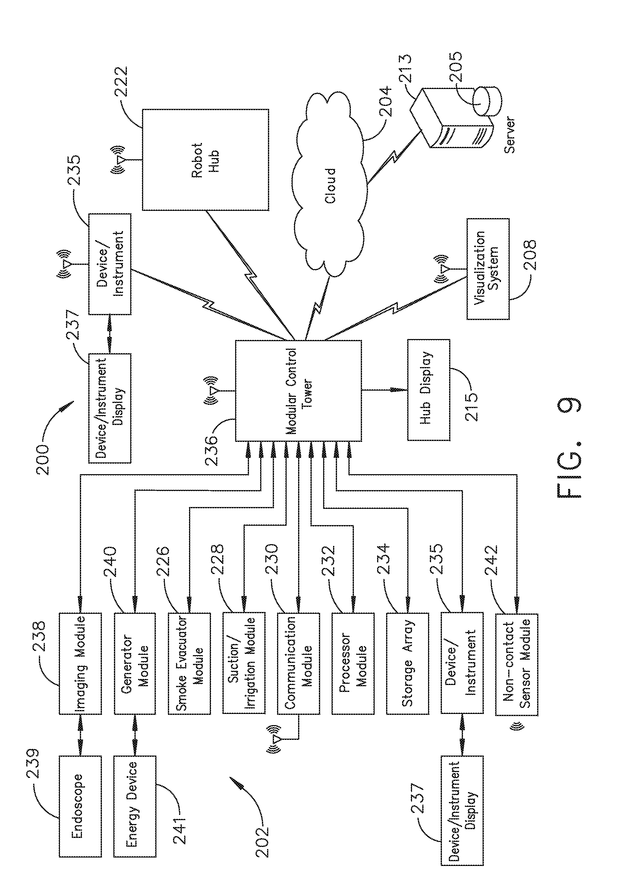
[0018] FIG. 9 illustrates a computer-implemented interactive surgical system, in accordance with at least one aspect of the present disclosure.
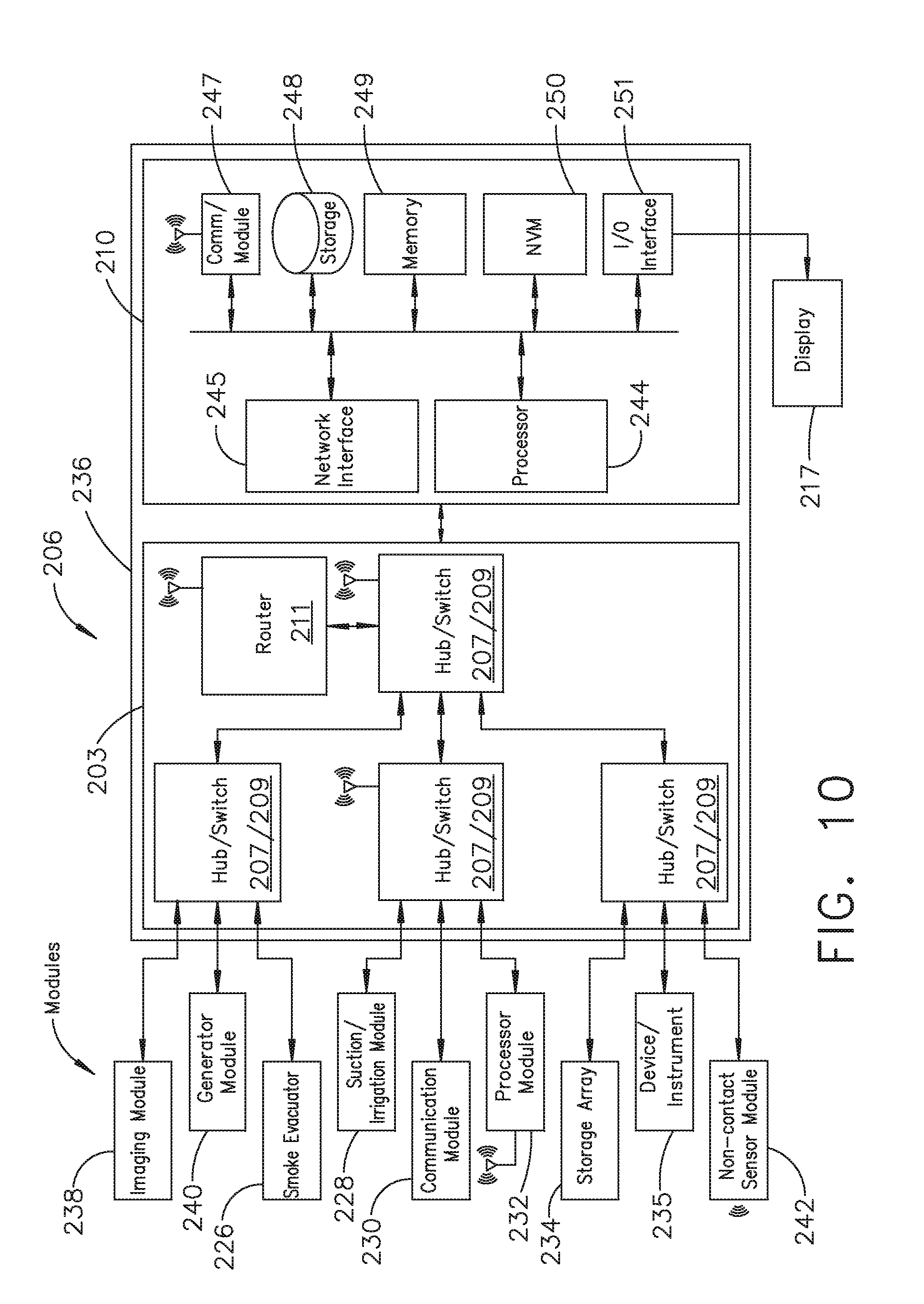
[0019] FIG. 10 illustrates a surgical hub comprising a plurality of modules coupled to the modular control tower, in accordance with at least one aspect of the present disclosure.
[0020] FIG. 11 illustrates one aspect of a Universal Serial Bus (USB) network hub device, in accordance with at least one aspect of the present disclosure.
[0021] FIG. 12 illustrates a logic diagram of a control system of a surgical instrument or tool, in accordance with at least one aspect of the present disclosure.
[0022] FIG. 13 illustrates a control circuit configured to control aspects of the surgical instrument or tool, in accordance with at least one aspect of the present disclosure.
[0023] FIG. 14 illustrates a combinational logic circuit configured to control aspects of the surgical instrument or tool, in accordance with at least one aspect of the present disclosure.
[0024] FIG. 15 illustrates a sequential logic circuit configured to control aspects of the surgical instrument or tool, in accordance with at least one aspect of the present disclosure.
[0025] FIG. 16 illustrates a surgical instrument or tool comprising a plurality of motors which can be activated to perform various functions, in accordance with at least one aspect of the present disclosure.
[0026] FIG. 17 is a schematic diagram of a robotic surgical instrument configured to operate a surgical tool described herein, in accordance with at least one aspect of the present disclosure.
[0027] FIG. 18 illustrates a block diagram of a surgical instrument programmed to control the distal translation of a displacement member, in accordance with at least one aspect of the present disclosure.
[0028] FIG. 19 is a schematic diagram of a surgical instrument configured to control various functions, in accordance with at least one aspect of the present disclosure.
[0029] FIG. 20 is a simplified block diagram of a generator configured to provide inductorless tuning, among other benefits, in accordance with at least one aspect of the present disclosure.
[0030] FIG. 21 illustrates an example of a generator, which is one form of the generator of FIG. 20, in accordance with at least one aspect of the present disclosure.
[0031] FIG. 22 illustrates a diagram of a surgical instrument centered on a linear staple transection line using the benefit of centering tools and techniques described in connection with FIGS. 23-35, in accordance with at least one aspect of the present disclosure.
[0032] FIGS. 23-25 illustrate a process of aligning an anvil trocar of a circular stapler to a staple overlap portion of a linear staple line created by a double-stapling technique, in accordance with at least one aspect of the present disclosure, where:
[0033] FIG. 23 illustrates an anvil trocar of a circular stapler that is not aligned with a staple overlap portion of a linear staple line created by a double-stapling technique;
[0034] FIG. 24 illustrates an anvil trocar of a circular stapler that is aligned with the center of the staple overlap portion of the linear staple line created by a double-stapling technique; and
[0035] FIG. 25 illustrates a centering tool displayed on a surgical hub display showing a staple overlap portion of a linear staple line created by a double-stapling technique to be cut out by a circular stapler, where the anvil trocar is not aligned with the staple overlap portion of the double staple line as shown in FIG. 23.
[0036] FIGS. 26 and 27 illustrate a before image and an after image of a centering tool, in accordance with at least one aspect of the present disclosure, where:
[0037] FIG. 26 illustrates an image of a projected cut path of an anvil trocar and circular knife before alignment with the target alignment ring circumscribing the image of the linear staple line over the image of the staple overlap portion presented on a surgical hub display; and
[0038] FIG. 27 illustrates an image of a projected cut path of an anvil trocar and circular knife after alignment with the target alignment ring circumscribing the image of the linear staple line over the image of the staple overlap portion presented on a surgical hub display.
[0039] FIGS. 28-30 illustrate a process of aligning an anvil trocar of a circular stapler to a center of a linear staple line, in accordance with at least one aspect of the present disclosure, where:
[0040] FIG. 28 illustrates the anvil trocar out of alignment with the center of the linear staple line;
[0041] FIG. 29 illustrates the anvil trocar in alignment with the center of the linear staple line; and
[0042] FIG. 30 illustrates a centering tool displayed on a surgical hub display of a linear staple line, where the anvil trocar is not aligned with the staple overlap portion of the double staple line as shown in FIG. 28.
[0043] FIG. 31 is an image of a standard reticle field view of a linear staple line transection of a surgical as viewed through a laparoscope displayed on the surgical hub display, in accordance with at least one aspect of the present disclosure.
[0044] FIG. 32 is an image of a laser-assisted reticle field of view of the surgical site shown in FIG. 31 before the anvil trocar and circular knife of the circular stapler are aligned to the center of the linear staple line, in accordance with at least one aspect of the present disclosure.
[0045] FIG. 33 is an image of a laser-assisted reticle field of view of the surgical site shown in FIG. 32 after the anvil trocar and circular knife of the circular stapler are aligned to the center of the linear staple line, in accordance with at least one aspect of the present disclosure.
[0046] FIG. 34 illustrates a non-contact inductive sensor implementation of a non-contact sensor to determine an anvil trocar location relative to the center of a staple line transection, in accordance with at least one aspect of the present disclosure.
[0047] FIGS. 35A and 35B illustrate one aspect of a non-contact capacitive sensor implementation of the non-contact sensor to determine an anvil trocar location relative to the center of a staple line transection, in accordance with at least one aspect of the present disclosure, where:
[0048] FIG. 35A shows the non-contact capacitive sensor without a nearby metal target; and
[0049] FIG. 35B shows the non-contact capacitive sensor near a metal target.
[0050] FIG. 36 is a logic flow diagram of a process depicting a control program or a logic configuration for aligning a surgical instrument, in accordance with at least one aspect of the present disclosure.
[0051] FIG. 37 illustrates a primary display of the surgical hub comprising a global and local display, in accordance with at least one aspect of the present disclosure.
[0052] FIG. 38 illustrates a primary display of the surgical hub, in accordance with at least one aspect of the present disclosure.
[0053] FIG. 39 illustrates a clamp stabilization sequence over a five second period, in accordance with at least one aspect of the present disclosure.
[0054] FIG. 40 illustrates a diagram of four separate wide angle view images of a surgical site at four separate times during the procedure, in accordance with at least one aspect of the present disclosure.
[0055] FIG. 41 is a graph of tissue creep clamp stabilization curves for two tissue types, in accordance with at least one aspect of the present disclosure.
[0056] FIG. 42 is a graph of time dependent proportionate fill of a clamp force stabilization curve, in accordance with at least one aspect of the present disclosure.
[0057] FIG. 43 is a graph of the role of tissue creep in the clamp force stabilization curve, in accordance with at least one aspect of the present disclosure.
[0058] FIGS. 44A and 44B illustrate two graphs for determining when the clamped tissue has reached creep stability, in accordance with at least one aspect of the present disclosure, where:
[0059] FIG. 44A illustrates a curve that represents a vector tangent angle d.theta. as a function of time; and
[0060] FIG. 44B illustrates a curve that represents change in force-to-close (.DELTA.FTC) as a function of time.
[0061] FIG. 45 illustrates an example of an augmented video image of a pre-operative video image augmented with data identifying displayed elements, in accordance with at least one aspect of the present disclosure.
[0062] FIG. 46 is a logic flow diagram of a process depicting a control program or a logic configuration to display images, in accordance with at least one aspect of the present disclosure.
[0063] FIG. 47 illustrates a communication system comprising an intermediate signal combiner positioned in the communication path between an imaging module and a surgical hub display, in accordance with at least one aspect of the present disclosure.
[0064] FIG. 48 illustrates an independent interactive headset worn by a surgeon to communicate data to the surgical hub, according to one aspect of the present disclosure.
[0065] FIG. 49 illustrates a method for controlling the usage of a device, in accordance with at least one aspect of the present disclosure, in accordance with at least one aspect of the present disclosure.
[0066] FIG. 50 illustrates a surgical system that includes a handle having a controller and a motor, an adapter releasably coupled to the handle, and a loading unit releasably coupled to the adapter, in accordance with at least one aspect of the present disclosure.
[0067] FIG. 51 illustrates a verbal Automated Endoscopic System for Optimal Positioning (AESOP) camera positioning system, in accordance with at least one aspect of the present disclosure.
[0068] FIG. 52 illustrates a multi-functional surgical control system and switching interface for virtual operating room integration, in accordance with at least one aspect of the present disclosure.
[0069] FIG. 53 illustrates a diagram of a beam source and combined beam detector system utilized as a device control mechanism in an operating theater, in accordance with at least one aspect of the present disclosure.
[0070] FIGS. 54A-E illustrate various types of sterile field control and data input consoles, in accordance with at least one aspect of the present disclosure, where:
[0071] FIG. 54A illustrates a single zone sterile field control and data input console;
[0072] FIG. 54B illustrates a multi zone sterile field control and data input console;
[0073] FIG. 54C illustrates a tethered sterile field control and data input console;
[0074] FIG. 54D illustrates a battery operated sterile field control and data input console; and
[0075] FIG. 54E illustrates a battery operated sterile field control and data input console.
[0076] FIGS. 55A-55B illustrate a sterile field console in use in a sterile field during a surgical procedure, in accordance with at least one aspect of the present disclosure, where:
[0077] FIG. 55A shows the sterile field console positioned in the sterile field near two surgeons engaged in an operation; and
[0078] FIG. 55B shows one of the surgeons tapping the touchscreen of the sterile field console.
[0079] FIG. 56 illustrates a process for accepting consult feeds from another operating room, in accordance with at least one aspect of the present disclosure.
[0080] FIG. 57 illustrates a standard technique for estimating vessel path and depth and device trajectory, in accordance with at least one aspect of the present disclosure.
[0081] FIGS. 58A-58D illustrate multiple real time views of images of a virtual anatomical detail for dissection, in accordance with at least one aspect of the present disclosure, where:
[0082] FIG. 58A is a perspective view of the virtual anatomical detail;
[0083] FIG. 58C is a side view of the virtual anatomical detail;
[0084] FIG. 58B is a perspective view of the virtual anatomical detail; and
[0085] FIG. 58D is a side view of the virtual anatomical detail.
[0086] FIGS. 59A-59B illustrate a touchscreen display that may be used within the sterile field, in accordance with at least one aspect of the present disclosure, where:
[0087] FIG. 59A illustrates an image of a surgical site displayed on a touchscreen display in portrait mode;
[0088] FIG. 59B shows the touchscreen display rotated in landscape mode and the surgeon uses his index finger to scroll the image in the direction of the arrows;
[0089] FIG. 59C shows the surgeon using his index finger and thumb to pinch open the image in the direction of the arrows to zoom in;
[0090] FIG. 59D shows the surgeon using his index finger and thumb to pinch close the image in the direction of the arrows to zoom out; and
[0091] FIG. 59E shows the touchscreen display rotated in two directions indicated by arrows to enable the surgeon to view the image in different orientations.
[0092] FIG. 60 illustrates a surgical site employing a smart retractor comprising a direct interface control to a surgical hub, in accordance with at least one aspect of the present disclosure.
[0093] FIG. 61 illustrates a surgical site with a smart flexible sticker display attached to the body of a patient, in accordance with at least one aspect of the present disclosure.
[0094] FIG. 62 is a logic flow diagram of a process depicting a control program or a logic configuration to communicate from inside a sterile field to a device located outside the sterile field, in accordance with at least one aspect of the present disclosure.
[0095] FIG. 63 illustrates a system for performing surgery, in accordance with at least one aspect of the present disclosure.
[0096] FIG. 64 illustrates a second layer of information overlaying a first layer of information, in accordance with at least one aspect of the present disclosure.
[0097] FIG. 65 depicts a perspective view of a surgeon using a surgical instrument that includes a handle assembly housing and a wireless circuit board during a surgical procedure, with the surgeon wearing a set of safety glasses, in accordance with at least one aspect of the present disclosure.
[0098] FIG. 66 is a schematic diagram of a feedback control system for controlling a surgical instrument, in accordance with at least one aspect of the present disclosure.
[0099] FIG. 67 illustrates a feedback controller that includes an on-screen display module and a heads up display (HUD) module, in accordance with at least one aspect of the present disclosure.
[0100] FIG. 68 is a timeline depicting situational awareness of a surgical hub, in accordance with at least one aspect of the present disclosure.
DESCRIPTION
[0101] Applicant of the present application owns the following U.S. Provisional Patent Applications, filed on Mar. 28, 2018, each of which is herein incorporated by reference in its entirety: [0102] U.S. Provisional Patent Application Ser. No. 62/649,302, titled INTERACTIVE SURGICAL SYSTEMS WITH ENCRYPTED COMMUNICATION CAPABILITIES; [0103] U.S. Provisional Patent Application Ser. No. 62/649,294, titled DATA STRIPPING METHOD TO INTERROGATE PATIENT RECORDS AND CREATE ANONYMIZED RECORD; [0104] U.S. Provisional Patent Application Ser. No. 62/649,300, titled SURGICAL HUB SITUATIONAL AWARENESS; [0105] U.S. Provisional Patent Application Ser. No. 62/649,309, titled SURGICAL HUB SPATIAL AWARENESS TO DETERMINE DEVICES IN OPERATING THEATER; [0106] U.S. Provisional Patent Application Ser. No. 62/649,310, titled COMPUTER IMPLEMENTED INTERACTIVE SURGICAL SYSTEMS; [0107] U.S. Provisional Patent Application Ser. No. 62/649,291, titled USE OF LASER LIGHT AND RED-GREEN-BLUE COLORATION TO DETERMINE PROPERTIES OF BACK SCATTERED LIGHT; [0108] U.S. Provisional Patent Application Ser. No. 62/649,296, titled ADAPTIVE CONTROL PROGRAM UPDATES FOR SURGICAL DEVICES; [0109] U.S. Provisional Patent Application Ser. No. 62/649,333, titled CLOUD-BASED MEDICAL ANALYTICS FOR CUSTOMIZATION AND RECOMMENDATIONS TO A USER; [0110] U.S. Provisional Patent Application Ser. No. 62/649,327, titled CLOUD-BASED MEDICAL ANALYTICS FOR SECURITY AND AUTHENTICATION TRENDS AND REACTIVE MEASURES; [0111] U.S. Provisional Patent Application Ser. No. 62/649,315, titled DATA HANDLING AND PRIORITIZATION IN A CLOUD ANALYTICS NETWORK; [0112] U.S. Provisional Patent Application Ser. No. 62/649,313, titled CLOUD INTERFACE FOR COUPLED SURGICAL DEVICES; [0113] U.S. Provisional Patent Application Ser. No. 62/649,320, titled DRIVE ARRANGEMENTS FOR ROBOT-ASSISTED SURGICAL PLATFORMS; [0114] U.S. Provisional Patent Application Ser. No. 62/649,307, titled AUTOMATIC TOOL ADJUSTMENTS FOR ROBOT-ASSISTED SURGICAL PLATFORMS; and [0115] U.S. Provisional Patent Application Ser. No. 62/649,323, titled SENSING ARRANGEMENTS FOR ROBOT-ASSISTED SURGICAL PLATFORMS.
[0116] Applicant of the present application owns the following U.S. Patent Applications, filed on Mar. 29, 2018, each of which is herein incorporated by reference in its entirety: [0117] U.S. patent application Ser. No. ______, titled INTERACTIVE SURGICAL SYSTEMS WITH ENCRYPTED COMMUNICATION CAPABILITIES; Attorney Docket No. END8499USNP/170766; [0118] U.S. patent application Ser. No. ______, titled INTERACTIVE SURGICAL SYSTEMS WITH CONDITION HANDLING OF DEVICES AND DATA CAPABILITIES; [0119] U.S. patent application Ser. No. ______, titled SURGICAL HUB COORDINATION OF CONTROL AND COMMUNICATION OF OPERATING ROOM DEVICES; Attorney Docket No. END8499USNP2/170766-2; [0120] U.S. patent application Ser. No. ______, titled SPATIAL AWARENESS OF SURGICAL HUBS IN OPERATING ROOMS; Attorney Docket No. END8499USNP3/170766-3; [0121] U.S. patent application Ser. No. ______, titled COOPERATIVE UTILIZATION OF DATA DERIVED FROM SECONDARY SOURCES BY INTELLIGENT SURGICAL HUBS; Attorney Docket No. END8499USNP4/170766-4; [0122] U.S. patent application Ser. No. ______, titled SURGICAL HUB CONTROL ARRANGEMENTS; Attorney Docket No. END8499USNP5/170766-5; [0123] U.S. patent application Ser. No. ______, titled DATA STRIPPING METHOD TO INTERROGATE PATIENT RECORDS AND CREATE ANONYMIZED RECORD; Attorney Docket No. END8500USNP/170767; [0124] U.S. patent application Ser. No. ______, titled COMMUNICATION HUB AND STORAGE DEVICE FOR STORING PARAMETERS AND STATUS OF A SURGICAL DEVICE TO BE SHARED WITH CLOUD BASED ANALYTICS SYSTEMS; Attorney Docket No. END8500USNP1/170767-1; [0125] U.S. patent application Ser. No. ______, titled SELF DESCRIBING DATA PACKETS GENERATED AT AN ISSUING INSTRUMENT; Attorney Docket No. END8500USNP2/170767-2; [0126] U.S. patent application Ser. No. ______, titled DATA PAIRING TO INTERCONNECT A DEVICE MEASURED PARAMETER WITH AN OUTCOME; Attorney Docket No. END8500USNP3/170767-3; [0127] U.S. patent application Ser. No. ______, titled SURGICAL HUB SITUATIONAL AWARENESS; Attorney Docket No. END8501USNP/170768; [0128] U.S. patent application Ser. No. ______, titled SURGICAL SYSTEM DISTRIBUTED PROCESSING; Attorney Docket No. END8501USNP1/170768-1; [0129] U.S. patent application Ser. No. ______, titled AGGREGATION AND REPORTING OF SURGICAL HUB DATA; Attorney Docket No. END8501USNP2/170768-2; [0130] U.S. patent application Ser. No. ______, titled DISPLAY OF ALIGNMENT OF STAPLE CARTRIDGE TO PRIOR LINEAR STAPLE LINE; Attorney Docket No. END8502USNP1/170769-1; [0131] U.S. patent application Ser. No. ______, titled STERILE FIELD INTERACTIVE CONTROL DISPLAYS; Attorney Docket No. END8502USNP2/170769-2; [0132] U.S. patent application Ser. No. ______, titled COMPUTER IMPLEMENTED INTERACTIVE SURGICAL SYSTEMS; Attorney Docket No. END8503USNP/170770; [0133] U.S. patent application Ser. No. ______, titled USE OF LASER LIGHT AND RED-GREEN-BLUE COLORATION TO DETERMINE PROPERTIES OF BACK SCATTERED LIGHT; Attorney Docket No. END8504USNP/170771; [0134] U.S. patent application Ser. No. ______, titled CHARACTERIZATION OF TISSUE IRREGULARITIES THROUGH THE USE OF MONO-CHROMATIC LIGHT REFRACTIVITY; Attorney Docket No. END8504USNP1/170771-1; and [0135] U.S. patent application Ser. No. ______, titled DUAL CMOS ARRAY IMAGING; Attorney Docket No. END8504USNP2/170771-2.
[0136] Applicant of the present application owns the following U.S. Patent Applications, filed on Mar. 29, 2018, each of which is herein incorporated by reference in its entirety: [0137] U.S. patent application Ser. No. ______, titled ADAPTIVE CONTROL PROGRAM UPDATES FOR SURGICAL DEVICES; Attorney Docket No. END8506USNP/170773; [0138] U.S. patent application Ser. No. ______, titled ADAPTIVE CONTROL PROGRAM UPDATES FOR SURGICAL HUBS; Attorney Docket No. END8506USNP1/170773-1; [0139] U.S. patent application Ser. No. ______, titled CLOUD-BASED MEDICAL ANALYTICS FOR CUSTOMIZATION AND RECOMMENDATIONS TO A USER; Attorney Docket No. END8507USNP/170774; [0140] U.S. patent application Ser. No. ______, titled CLOUD-BASED MEDICAL ANALYTICS FOR LINKING OF LOCAL USAGE TRENDS WITH THE RESOURCE ACQUISITION BEHAVIORS OF LARGER DATA SET; Attorney Docket No. END8507USNP1/170774-1; [0141] U.S. patent application Ser. No. ______, titled CLOUD-BASED MEDICAL ANALYTICS FOR MEDICAL FACILITY SEGMENTED INDIVIDUALIZATION OF INSTRUMENT FUNCTION; Attorney Docket No. END8507USNP2/170774-2; [0142] U.S. patent application Ser. No. ______, titled CLOUD-BASED MEDICAL ANALYTICS FOR SECURITY AND AUTHENTICATION TRENDS AND REACTIVE MEASURES; Attorney Docket No. END8508USNP/170775; [0143] U.S. patent application Ser. No. ______, titled DATA HANDLING AND PRIORITIZATION IN A CLOUD ANALYTICS NETWORK; Attorney Docket No. END8509USNP/170776; and [0144] U.S. patent application Ser. No. ______, titled CLOUD INTERFACE FOR COUPLED SURGICAL DEVICES; Attorney Docket No. END8510USNP/170777.
[0145] Applicant of the present application owns the following U.S. Patent Applications, filed on Mar. 29, 2018, each of which is herein incorporated by reference in its entirety: [0146] U.S. patent application Ser. No. ______, titled DRIVE ARRANGEMENTS FOR ROBOT-ASSISTED SURGICAL PLATFORMS; Attorney Docket No. END8511USNP/170778; [0147] U.S. patent application Ser. No. ______, titled COMMUNICATION ARRANGEMENTS FOR ROBOT-ASSISTED SURGICAL PLATFORMS; Attorney Docket No. END8511USNP1/170778-1; [0148] U.S. patent application Ser. No. ______, titled CONTROLS FOR ROBOT-ASSISTED SURGICAL PLATFORMS; Attorney Docket No. END8511USNP2/170778-2; [0149] U.S. patent application Ser. No. ______, titled AUTOMATIC TOOL ADJUSTMENTS FOR ROBOT-ASSISTED SURGICAL PLATFORMS; Attorney Docket No. END8512USNP/170779; [0150] U.S. patent application Ser. No. ______, titled CONTROLLERS FOR ROBOT-ASSISTED SURGICAL PLATFORMS; Attorney Docket No. END8512USNP1/170779-1; [0151] U.S. patent application Ser. No. ______, titled COOPERATIVE SURGICAL ACTIONS FOR ROBOT-ASSISTED SURGICAL PLATFORMS; Attorney Docket No. END8512USNP2/170779-2; [0152] U.S. patent application Ser. No. ______, titled DISPLAY ARRANGEMENTS FOR ROBOT-ASSISTED SURGICAL PLATFORMS; Attorney Docket No. END8512USNP3/170779-3; and [0153] U.S. patent application Ser. No. ______, titled SENSING ARRANGEMENTS FOR ROBOT-ASSISTED SURGICAL PLATFORMS; Attorney Docket No. END8513USNP/170780.
[0154] Before explaining various aspects of surgical devices and generators in detail, it should be noted that the illustrative examples are not limited in application or use to the details of construction and arrangement of parts illustrated in the accompanying drawings and description. The illustrative examples may be implemented or incorporated in other aspects, variations and modifications, and may be practiced or carried out in various ways. Further, unless otherwise indicated, the terms and expressions employed herein have been chosen for the purpose of describing the illustrative examples for the convenience of the reader and are not for the purpose of limitation thereof. Also, it will be appreciated that one or more of the following-described aspects, expressions of aspects, and/or examples, can be combined with any one or more of the other following-described aspects, expressions of aspects and/or examples.
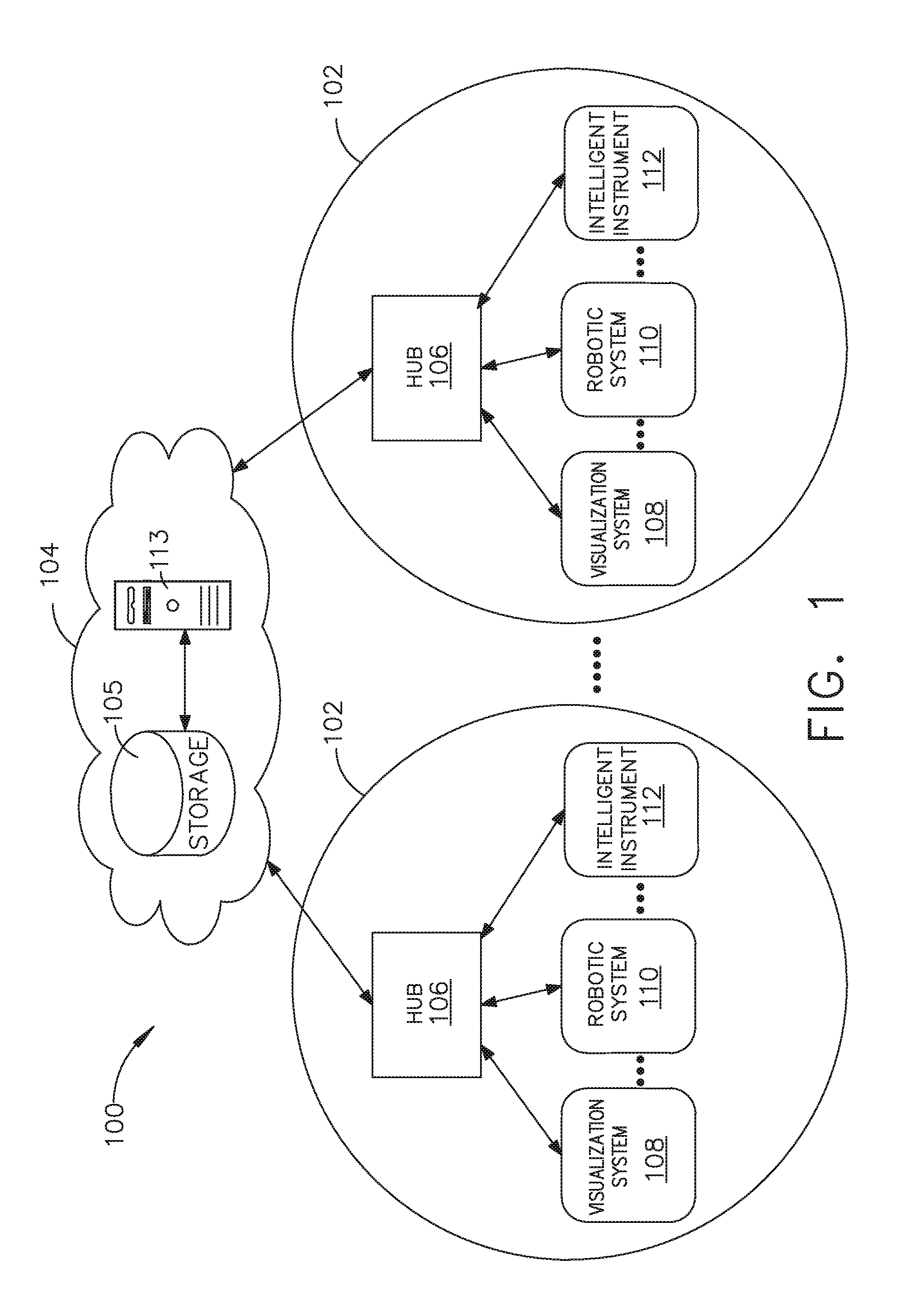
[0155] Referring to FIG. 1, a computer-implemented interactive surgical system 100 includes one or more surgical systems 102 and a cloud-based system (e.g., the cloud 104 that may include a remote server 113 coupled to a storage device 105). Each surgical system 102 includes at least one surgical hub 106 in communication with the cloud 104 that may include a remote server 113. In one example, as illustrated in FIG. 1, the surgical system 102 includes a visualization system 108, a robotic system 110, and a handheld intelligent surgical instrument 112, which are configured to communicate with one another and/or the hub 106. In some aspects, a surgical system 102 may include an M number of hubs 106, an N number of visualization systems 108, an O number of robotic systems 110, and a P number of handheld intelligent surgical instruments 112, where M, N, O, and P are integers greater than or equal to one.
[0156] FIG. 3 depicts an example of a surgical system 102 being used to perform a surgical procedure on a patient who is lying down on an operating table 114 in a surgical operating room 116. A robotic system 110 is used in the surgical procedure as a part of the surgical system 102. The robotic system 110 includes a surgeon's console 118, a patient side cart 120 (surgical robot), and a surgical robotic hub 122. The patient side cart 120 can manipulate at least one removably coupled surgical tool 117 through a minimally invasive incision in the body of the patient while the surgeon views the surgical site through the surgeon's console 118. An image of the surgical site can be obtained by a medical imaging device 124, which can be manipulated by the patient side cart 120 to orient the imaging device 124. The robotic hub 122 can be used to process the images of the surgical site for subsequent display to the surgeon through the surgeon's console 118.
[0157] Other types of robotic systems can be readily adapted for use with the surgical system 102. Various examples of robotic systems and surgical tools that are suitable for use with the present disclosure are described in U.S. Provisional Patent Application Ser. No. 62/611,339, titled ROBOT ASSISTED SURGICAL PLATFORM, filed Dec. 28, 2017, the disclosure of which is herein incorporated by reference in its entirety.
[0158] Various examples of cloud-based analytics that are performed by the cloud 104, and are suitable for use with the present disclosure, are described in U.S. Provisional Patent Application Ser. No. 62/611,340, titled CLOUD-BASED MEDICAL ANALYTICS, filed Dec. 28, 2017, the disclosure of which is herein incorporated by reference in its entirety.
[0159] In various aspects, the imaging device 124 includes at least one image sensor and one or more optical components. Suitable image sensors include, but are not limited to, Charge-Coupled Device (CCD) sensors and Complementary Metal-Oxide Semiconductor (CMOS) sensors.
[0160] The optical components of the imaging device 124 may include one or more illumination sources and/or one or more lenses. The one or more illumination sources may be directed to illuminate portions of the surgical field. The one or more image sensors may receive light reflected or refracted from the surgical field, including light reflected or refracted from tissue and/or surgical instruments.
[0161] The one or more illumination sources may be configured to radiate electromagnetic energy in the visible spectrum as well as the invisible spectrum. The visible spectrum, sometimes referred to as the optical spectrum or luminous spectrum, is that portion of the electromagnetic spectrum that is visible to (i.e., can be detected by) the human eye and may be referred to as visible light or simply light. A typical human eye will respond to wavelengths in air that are from about 380 nm to about 750 nm.
[0162] The invisible spectrum (i.e., the non-luminous spectrum) is that portion of the electromagnetic spectrum that lies below and above the visible spectrum (i.e., wavelengths below about 380 nm and above about 750 nm). The invisible spectrum is not detectable by the human eye. Wavelengths greater than about 750 nm are longer than the red visible spectrum, and they become invisible infrared (IR), microwave, and radio electromagnetic radiation. Wavelengths less than about 380 nm are shorter than the violet spectrum, and they become invisible ultraviolet, x-ray, and gamma ray electromagnetic radiation.
[0163] In various aspects, the imaging device 124 is configured for use in a minimally invasive procedure. Examples of imaging devices suitable for use with the present disclosure include, but not limited to, an arthroscope, angioscope, bronchoscope, choledochoscope, colonoscope, cytoscope, duodenoscope, enteroscope, esophagogastro-duodenoscope (gastroscope), endoscope, laryngoscope, nasopharyngo-neproscope, sigmoidoscope, thoracoscope, and ureteroscope.
[0164] In one aspect, the imaging device employs multi-spectrum monitoring to discriminate topography and underlying structures. A multi-spectral image is one that captures image data within specific wavelength ranges across the electromagnetic spectrum. The wavelengths may be separated by filters or by the use of instruments that are sensitive to particular wavelengths, including light from frequencies beyond the visible light range, e.g., IR and ultraviolet. Spectral imaging can allow extraction of additional information the human eye fails to capture with its receptors for red, green, and blue. The use of multi-spectral imaging is described in greater detail under the heading "Advanced Imaging Acquisition Module" in U.S. Provisional Patent Application Ser. No. 62/611,341, titled INTERACTIVE SURGICAL PLATFORM, filed Dec. 28, 2017, the disclosure of which is herein incorporated by reference in its entirety. Multi-spectrum monitoring can be a useful tool in relocating a surgical field after a surgical task is completed to perform one or more of the previously described tests on the treated tissue.
[0165] It is axiomatic that strict sterilization of the operating room and surgical equipment is required during any surgery. The strict hygiene and sterilization conditions required in a "surgical theater," i.e., an operating or treatment room, necessitate the highest possible sterility of all medical devices and equipment. Part of that sterilization process is the need to sterilize anything that comes in contact with the patient or penetrates the sterile field, including the imaging device 124 and its attachments and components. It will be appreciated that the sterile field may be considered a specified area, such as within a tray or on a sterile towel, that is considered free of microorganisms, or the sterile field may be considered an area, immediately around a patient, who has been prepared for a surgical procedure. The sterile field may include the scrubbed team members, who are properly attired, and all furniture and fixtures in the area.
[0166] In various aspects, the visualization system 108 includes one or more imaging sensors, one or more image processing units, one or more storage arrays, and one or more displays that are strategically arranged with respect to the sterile field, as illustrated in FIG. 2. In one aspect, the visualization system 108 includes an interface for HL7, PACS, and EMR. Various components of the visualization system 108 are described under the heading "Advanced Imaging Acquisition Module" in U.S. Provisional Patent Application Ser. No. 62/611,341, titled INTERACTIVE SURGICAL PLATFORM, filed Dec. 28, 2017, the disclosure of which is herein incorporated by reference in its entirety.
[0167] As illustrated in FIG. 2, a primary display 119 is positioned in the sterile field to be visible to an operator at the operating table 114. In addition, a visualization tower 111 is positioned outside the sterile field. The visualization tower 111 includes a first non-sterile display 107 and a second non-sterile display 109, which face away from each other. The visualization system 108, guided by the hub 106, is configured to utilize the displays 107, 109, and 119 to coordinate information flow to operators inside and outside the sterile field. For example, the hub 106 may cause the visualization system 108 to display a snap-shot of a surgical site, as recorded by an imaging device 124, on a non-sterile display 107 or 109, while maintaining a live feed of the surgical site on the primary display 119. The snap-shot on the non-sterile display 107 or 109 can permit a non-sterile operator to perform a diagnostic step relevant to the surgical procedure, for example.
[0168] In one aspect, the hub 106 is also configured to route a diagnostic input or feedback entered by a non-sterile operator at the visualization tower 111 to the primary display 119 within the sterile field, where it can be viewed by a sterile operator at the operating table. In one example, the input can be in the form of a modification to the snap-shot displayed on the non-sterile display 107 or 109, which can be routed to the primary display 119 by the hub 106.
[0169] Referring to FIG. 2, a surgical instrument 112 is being used in the surgical procedure as part of the surgical system 102. The hub 106 is also configured to coordinate information flow to a display of the surgical instrument 112. For example, in U.S. Provisional Patent Application Ser. No. 62/611,341, titled INTERACTIVE SURGICAL PLATFORM, filed Dec. 28, 2017, the disclosure of which is herein incorporated by reference in its entirety. A diagnostic input or feedback entered by a non-sterile operator at the visualization tower 111 can be routed by the hub 106 to the surgical instrument display 115 within the sterile field, where it can be viewed by the operator of the surgical instrument 112. Example surgical instruments that are suitable for use with the surgical system 102 are described under the heading "Surgical Instrument Hardware" and in U.S. Provisional Patent Application Ser. No. 62/611,341, titled INTERACTIVE SURGICAL PLATFORM, filed Dec. 28, 2017, the disclosure of which is herein incorporated by reference in its entirety, for example.
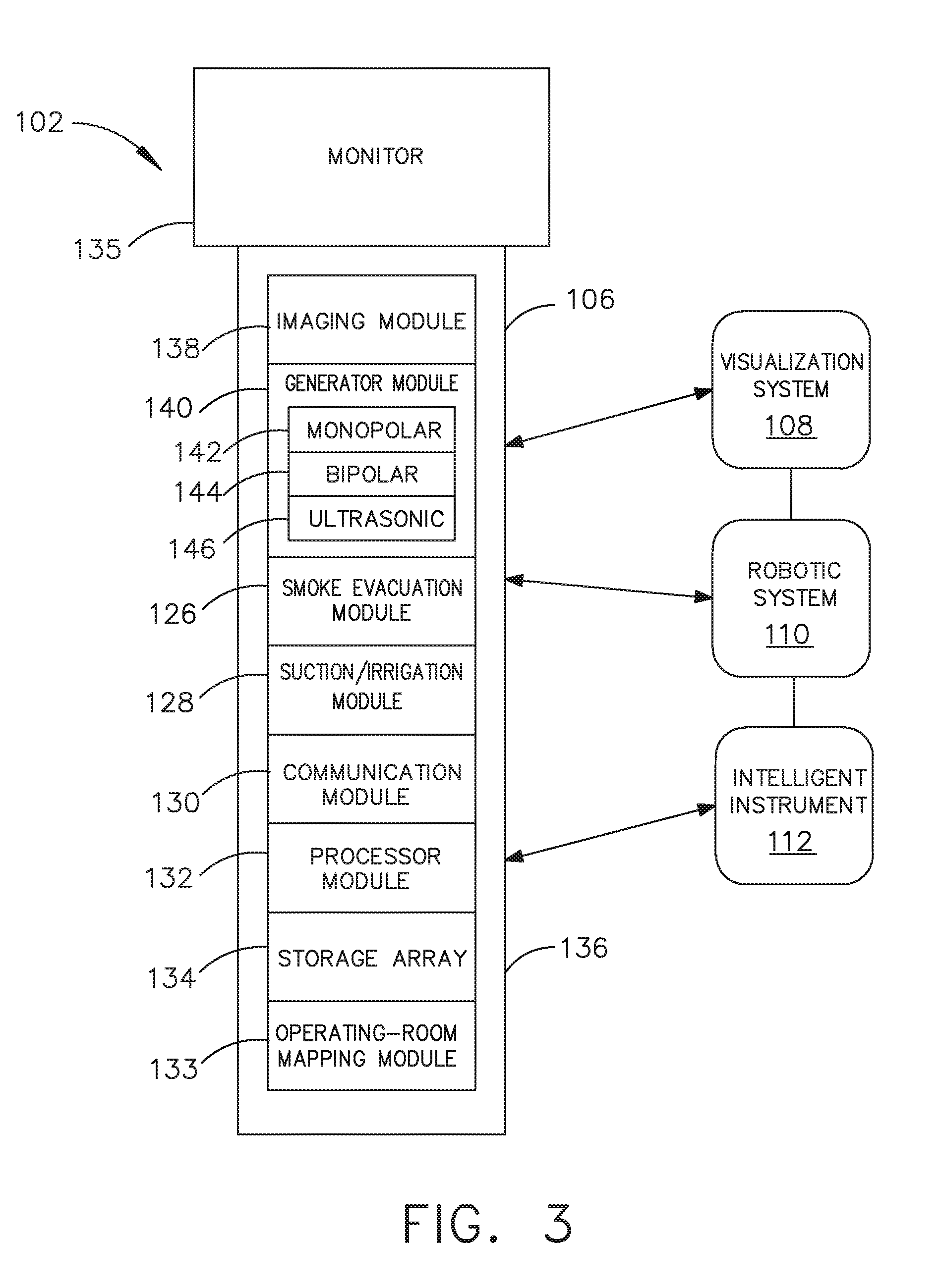
[0170] Referring now to FIG. 3, a hub 106 is depicted in communication with a visualization system 108, a robotic system 110, and a handheld intelligent surgical instrument 112. The hub 106 includes a hub display 135, an imaging module 138, a generator module 140, a communication module 130, a processor module 132, and a storage array 134. In certain aspects, as illustrated in FIG. 3, the hub 106 further includes a smoke evacuation module 126 and/or a suction/irrigation module 128.
[0171] During a surgical procedure, energy application to tissue, for sealing and/or cutting, is generally associated with smoke evacuation, suction of excess fluid, and/or irrigation of the tissue. Fluid, power, and/or data lines from different sources are often entangled during the surgical procedure. Valuable time can be lost addressing this issue during a surgical procedure. Detangling the lines may necessitate disconnecting the lines from their respective modules, which may require resetting the modules. The hub modular enclosure 136 offers a unified environment for managing the power, data, and fluid lines, which reduces the frequency of entanglement between such lines.
[0172] Aspects of the present disclosure present a surgical hub for use in a surgical procedure that involves energy application to tissue at a surgical site. The surgical hub includes a hub enclosure and a combo generator module slidably receivable in a docking station of the hub enclosure. The docking station includes data and power contacts. The combo generator module includes two or more of an ultrasonic energy generator component, a bipolar RF energy generator component, and a monopolar RF energy generator component that are housed in a single unit. In one aspect, the combo generator module also includes a smoke evacuation component, at least one energy delivery cable for connecting the combo generator module to a surgical instrument, at least one smoke evacuation component configured to evacuate smoke, fluid, and/or particulates generated by the application of therapeutic energy to the tissue, and a fluid line extending from the remote surgical site to the smoke evacuation component.
[0173] In one aspect, the fluid line is a first fluid line and a second fluid line extends from the remote surgical site to a suction and irrigation module slidably received in the hub enclosure. In one aspect, the hub enclosure comprises a fluid interface.
[0174] Certain surgical procedures may require the application of more than one energy type to the tissue. One energy type may be more beneficial for cutting the tissue, while another different energy type may be more beneficial for sealing the tissue. For example, a bipolar generator can be used to seal the tissue while an ultrasonic generator can be used to cut the sealed tissue. Aspects of the present disclosure present a solution where a hub modular enclosure 136 is configured to accommodate different generators, and facilitate an interactive communication therebetween. One of the advantages of the hub modular enclosure 136 is enabling the quick removal and/or replacement of various modules.
[0175] Aspects of the present disclosure present a modular surgical enclosure for use in a surgical procedure that involves energy application to tissue. The modular surgical enclosure includes a first energy-generator module, configured to generate a first energy for application to the tissue, and a first docking station comprising a first docking port that includes first data and power contacts, wherein the first energy-generator module is slidably movable into an electrical engagement with the power and data contacts and wherein the first energy-generator module is slidably movable out of the electrical engagement with the first power and data contacts.
[0176] Further to the above, the modular surgical enclosure also includes a second energy-generator module configured to generate a second energy, different than the first energy, for application to the tissue, and a second docking station comprising a second docking port that includes second data and power contacts, wherein the second energy-generator module is slidably movable into an electrical engagement with the power and data contacts, and wherein the second energy-generator module is slidably movable out of the electrical engagement with the second power and data contacts.
[0177] In addition, the modular surgical enclosure also includes a communication bus between the first docking port and the second docking port, configured to facilitate communication between the first energy-generator module and the second energy-generator module.
[0178] Referring to FIGS. 3-7, aspects of the present disclosure are presented for a hub modular enclosure 136 that allows the modular integration of a generator module 140, a smoke evacuation module 126, and a suction/irrigation module 128. The hub modular enclosure 136 further facilitates interactive communication between the modules 140, 126, 128. As illustrated in FIG. 5, the generator module 140 can be a generator module with integrated monopolar, bipolar, and ultrasonic components supported in a single housing unit 139 slidably insertable into the hub modular enclosure 136. As illustrated in FIG. 5, the generator module 140 can be configured to connect to a monopolar device 146, a bipolar device 147, and an ultrasonic device 148. Alternatively, the generator module 140 may comprise a series of monopolar, bipolar, and/or ultrasonic generator modules that interact through the hub modular enclosure 136. The hub modular enclosure 136 can be configured to facilitate the insertion of multiple generators and interactive communication between the generators docked into the hub modular enclosure 136 so that the generators would act as a single generator.
[0179] In one aspect, the hub modular enclosure 136 comprises a modular power and communication backplane 149 with external and wireless communication headers to enable the removable attachment of the modules 140, 126, 128 and interactive communication therebetween.
[0180] In one aspect, the hub modular enclosure 136 includes docking stations, or drawers, 151, herein also referred to as drawers, which are configured to slidably receive the modules 140, 126, 128. FIG. 4 illustrates a partial perspective view of a surgical hub enclosure 136, and a combo generator module 145 slidably receivable in a docking station 151 of the surgical hub enclosure 136. A docking port 152 with power and data contacts on a rear side of the combo generator module 145 is configured to engage a corresponding docking port 150 with power and data contacts of a corresponding docking station 151 of the hub modular enclosure 136 as the combo generator module 145 is slid into position within the corresponding docking station 151 of the hub module enclosure 136. In one aspect, the combo generator module 145 includes a bipolar, ultrasonic, and monopolar module and a smoke evacuation module integrated together into a single housing unit 139, as illustrated in FIG. 5.
[0181] In various aspects, the smoke evacuation module 126 includes a fluid line 154 that conveys captured/collected smoke and/or fluid away from a surgical site and to, for example, the smoke evacuation module 126. Vacuum suction originating from the smoke evacuation module 126 can draw the smoke into an opening of a utility conduit at the surgical site. The utility conduit, coupled to the fluid line, can be in the form of a flexible tube terminating at the smoke evacuation module 126. The utility conduit and the fluid line define a fluid path extending toward the smoke evacuation module 126 that is received in the hub enclosure 136.
[0182] In various aspects, the suction/irrigation module 128 is coupled to a surgical tool comprising an aspiration fluid line and a suction fluid line. In one example, the aspiration and suction fluid lines are in the form of flexible tubes extending from the surgical site toward the suction/irrigation module 128. One or more drive systems can be configured to cause irrigation and aspiration of fluids to and from the surgical site.
[0183] In one aspect, the surgical tool includes a shaft having an end effector at a distal end thereof and at least one energy treatment associated with the end effector, an aspiration tube, and an irrigation tube. The aspiration tube can have an inlet port at a distal end thereof and the aspiration tube extends through the shaft. Similarly, an irrigation tube can extend through the shaft and can have an inlet port in proximity to the energy deliver implement. The energy deliver implement is configured to deliver ultrasonic and/or RF energy to the surgical site and is coupled to the generator module 140 by a cable extending initially through the shaft.
[0184] The irrigation tube can be in fluid communication with a fluid source, and the aspiration tube can be in fluid communication with a vacuum source. The fluid source and/or the vacuum source can be housed in the suction/irrigation module 128. In one example, the fluid source and/or the vacuum source can be housed in the hub enclosure 136 separately from the suction/irrigation module 128. In such example, a fluid interface can be configured to connect the suction/irrigation module 128 to the fluid source and/or the vacuum source.
[0185] In one aspect, the modules 140, 126, 128 and/or their corresponding docking stations on the hub modular enclosure 136 may include alignment features that are configured to align the docking ports of the modules into engagement with their counterparts in the docking stations of the hub modular enclosure 136. For example, as illustrated in FIG. 4, the combo generator module 145 includes side brackets 155 that are configured to slidably engage with corresponding brackets 156 of the corresponding docking station 151 of the hub modular enclosure 136. The brackets cooperate to guide the docking port contacts of the combo generator module 145 into an electrical engagement with the docking port contacts of the hub modular enclosure 136.
[0186] In some aspects, the drawers 151 of the hub modular enclosure 136 are the same, or substantially the same size, and the modules are adjusted in size to be received in the drawers 151. For example, the side brackets 155 and/or 156 can be larger or smaller depending on the size of the module. In other aspects, the drawers 151 are different in size and are each designed to accommodate a particular module.
[0187] Furthermore, the contacts of a particular module can be keyed for engagement with the contacts of a particular drawer to avoid inserting a module into a drawer with mismatching contacts.
[0188] As illustrated in FIG. 4, the docking port 150 of one drawer 151 can be coupled to the docking port 150 of another drawer 151 through a communications link 157 to facilitate an interactive communication between the modules housed in the hub modular enclosure 136. The docking ports 150 of the hub modular enclosure 136 may alternatively, or additionally, facilitate a wireless interactive communication between the modules housed in the hub modular enclosure 136. Any suitable wireless communication can be employed, such as for example Air Titan-Bluetooth.
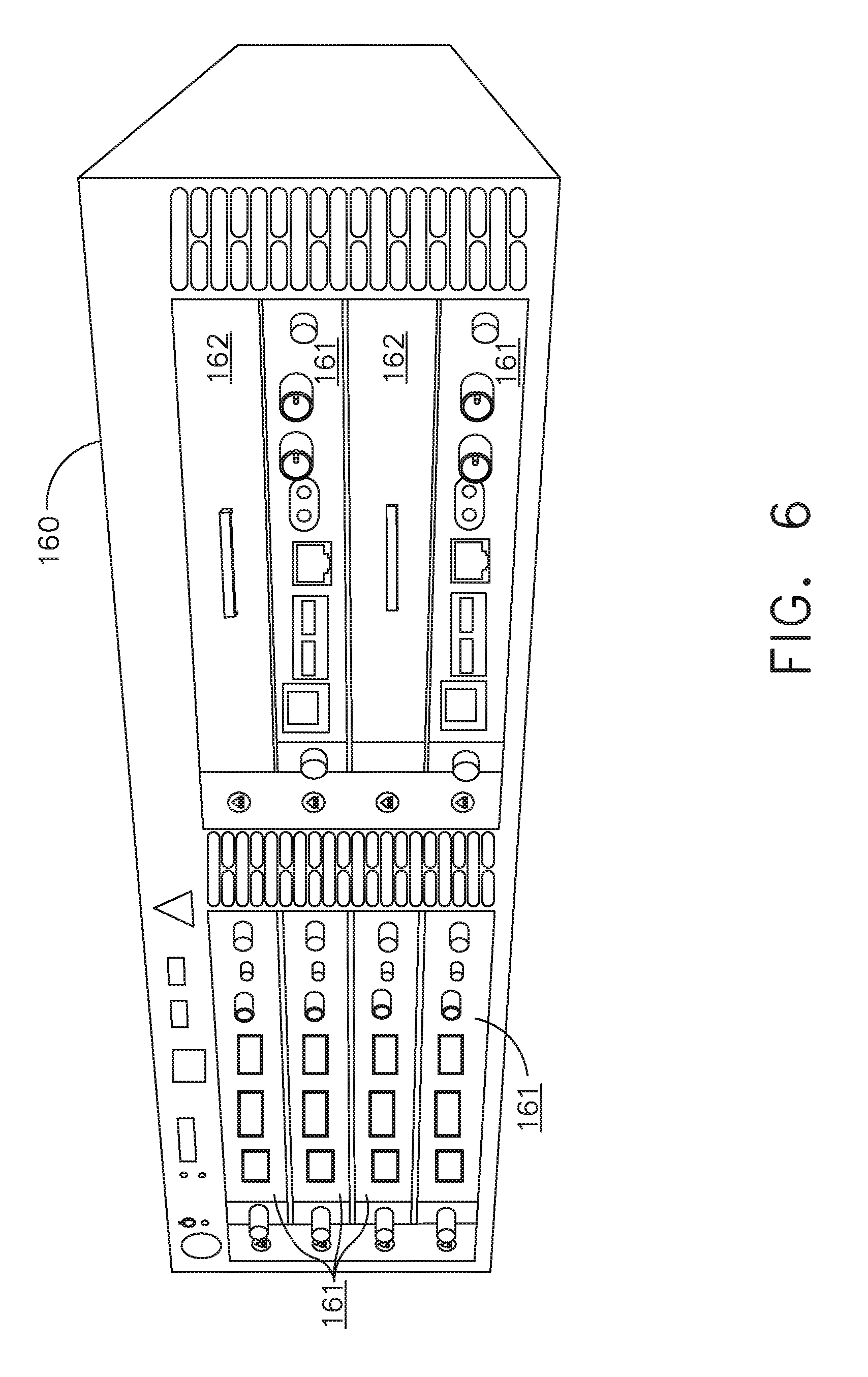
[0189] FIG. 6 illustrates individual power bus attachments for a plurality of lateral docking ports of a lateral modular housing 160 configured to receive a plurality of modules of a surgical hub 206. The lateral modular housing 160 is configured to laterally receive and interconnect the modules 161. The modules 161 are slidably inserted into docking stations 162 of lateral modular housing 160, which includes a backplane for interconnecting the modules 161. As illustrated in FIG. 6, the modules 161 are arranged laterally in the lateral modular housing 160. Alternatively, the modules 161 may be arranged vertically in a lateral modular housing.
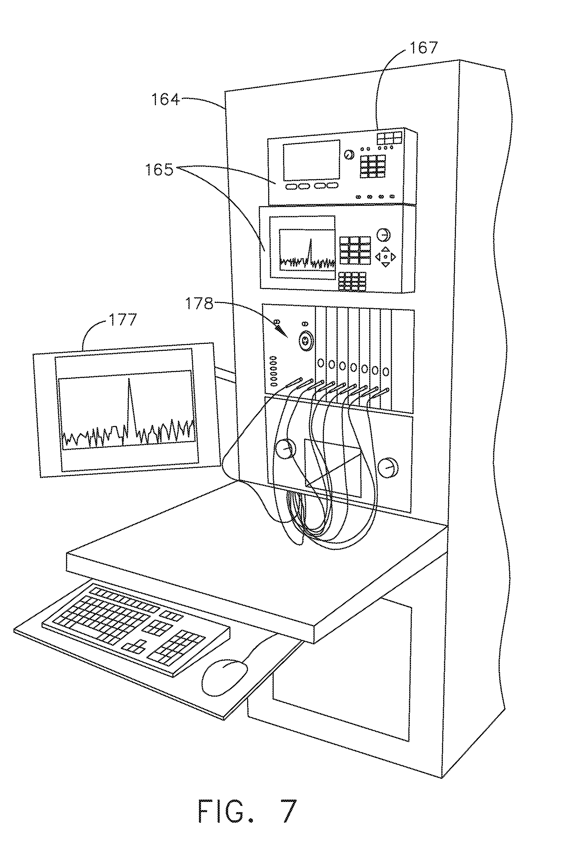
[0190] FIG. 7 illustrates a vertical modular housing 164 configured to receive a plurality of modules 165 of the surgical hub 106. The modules 165 are slidably inserted into docking stations, or drawers, 167 of vertical modular housing 164, which includes a backplane for interconnecting the modules 165. Although the drawers 167 of the vertical modular housing 164 are arranged vertically, in certain instances, a vertical modular housing 164 may include drawers that are arranged laterally. Furthermore, the modules 165 may interact with one another through the docking ports of the vertical modular housing 164. In the example of FIG. 7, a display 177 is provided for displaying data relevant to the operation of the modules 165. In addition, the vertical modular housing 164 includes a master module 178 housing a plurality of sub-modules that are slidably received in the master module 178.
[0191] In various aspects, the imaging module 138 comprises an integrated video processor and a modular light source and is adapted for use with various imaging devices. In one aspect, the imaging device is comprised of a modular housing that can be assembled with a light source module and a camera module. The housing can be a disposable housing. In at least one example, the disposable housing is removably coupled to a reusable controller, a light source module, and a camera module. The light source module and/or the camera module can be selectively chosen depending on the type of surgical procedure. In one aspect, the camera module comprises a CCD sensor. In another aspect, the camera module comprises a CMOS sensor. In another aspect, the camera module is configured for scanned beam imaging. Likewise, the light source module can be configured to deliver a white light or a different light, depending on the surgical procedure.
[0192] During a surgical procedure, removing a surgical device from the surgical field and replacing it with another surgical device that includes a different camera or a different light source can be inefficient. Temporarily losing sight of the surgical field may lead to undesirable consequences. The module imaging device of the present disclosure is configured to permit the replacement of a light source module or a camera module midstream during a surgical procedure, without having to remove the imaging device from the surgical field.
[0193] In one aspect, the imaging device comprises a tubular housing that includes a plurality of channels. A first channel is configured to slidably receive the camera module, which can be configured for a snap-fit engagement with the first channel. A second channel is configured to slidably receive the light source module, which can be configured for a snap-fit engagement with the second channel. In another example, the camera module and/or the light source module can be rotated into a final position within their respective channels. A threaded engagement can be employed in lieu of the snap-fit engagement.
[0194] In various examples, multiple imaging devices are placed at different positions in the surgical field to provide multiple views. The imaging module 138 can be configured to switch between the imaging devices to provide an optimal view. In various aspects, the imaging module 138 can be configured to integrate the images from the different imaging device.
[0195] Various image processors and imaging devices suitable for use with the present disclosure are described in U.S. Pat. No. 7,995,045, titled COMBINED SBI AND CONVENTIONAL IMAGE PROCESSOR, which issued on Aug. 9, 2011, which is herein incorporated by reference in its entirety. In addition, U.S. Pat. No. 7,982,776, titled SBI MOTION ARTIFACT REMOVAL APPARATUS AND METHOD, which issued on Jul. 19, 2011, which is herein incorporated by reference in its entirety, describes various systems for removing motion artifacts from image data. Such systems can be integrated with the imaging module 138. Furthermore, U.S. Patent Application Publication No. 2011/0306840, titled CONTROLLABLE MAGNETIC SOURCE TO FIXTURE INTRACORPOREAL APPARATUS, which published on Dec. 15, 2011, and U.S. Patent Application Publication No. 2014/0243597, titled SYSTEM FOR PERFORMING A MINIMALLY INVASIVE SURGICAL PROCEDURE, which published on Aug. 28, 2014, each of which is herein incorporated by reference in its entirety.
[0196] FIG. 8 illustrates a surgical data network 201 comprising a modular communication hub 203 configured to connect modular devices located in one or more operating theaters of a healthcare facility, or any room in a healthcare facility specially equipped for surgical operations, to a cloud-based system (e.g., the cloud 204 that may include a remote server 213 coupled to a storage device 205). In one aspect, the modular communication hub 203 comprises a network hub 207 and/or a network switch 209 in communication with a network router. The modular communication hub 203 also can be coupled to a local computer system 210 to provide local computer processing and data manipulation. The surgical data network 201 may be configured as passive, intelligent, or switching. A passive surgical data network serves as a conduit for the data, enabling it to go from one device (or segment) to another and to the cloud computing resources. An intelligent surgical data network includes additional features to enable the traffic passing through the surgical data network to be monitored and to configure each port in the network hub 207 or network switch 209. An intelligent surgical data network may be referred to as a manageable hub or switch. A switching hub reads the destination address of each packet and then forwards the packet to the correct port.
[0197] Modular devices 1a-1n located in the operating theater may be coupled to the modular communication hub 203. The network hub 207 and/or the network switch 209 may be coupled to a network router 211 to connect the devices 1a-1n to the cloud 204 or the local computer system 210. Data associated with the devices 1a-1n may be transferred to cloud-based computers via the router for remote data processing and manipulation. Data associated with the devices 1a-1n may also be transferred to the local computer system 210 for local data processing and manipulation. Modular devices 2a-2m located in the same operating theater also may be coupled to a network switch 209. The network switch 209 may be coupled to the network hub 207 and/or the network router 211 to connect to the devices 2a-2m to the cloud 204. Data associated with the devices 2a-2n may be transferred to the cloud 204 via the network router 211 for data processing and manipulation. Data associated with the devices 2a-2m may also be transferred to the local computer system 210 for local data processing and manipulation.
[0198] It will be appreciated that the surgical data network 201 may be expanded by interconnecting multiple network hubs 207 and/or multiple network switches 209 with multiple network routers 211. The modular communication hub 203 may be contained in a modular control tower configured to receive multiple devices 1a-1n/2a-2m. The local computer system 210 also may be contained in a modular control tower. The modular communication hub 203 is connected to a display 212 to display images obtained by some of the devices 1a-1n/2a-2m, for example during surgical procedures. In various aspects, the devices 1a-1n/2a-2m may include, for example, various modules such as an imaging module 138 coupled to an endoscope, a generator module 140 coupled to an energy-based surgical device, a smoke evacuation module 126, a suction/irrigation module 128, a communication module 130, a processor module 132, a storage array 134, a surgical device coupled to a display, and/or a non-contact sensor module, among other modular devices that may be connected to the modular communication hub 203 of the surgical data network 201.
[0199] In one aspect, the surgical data network 201 may comprise a combination of network hub(s), network switch(es), and network router(s) connecting the devices 1a-1n/2a-2m to the cloud. Any one of or all of the devices 1a-1n/2a-2m coupled to the network hub or network switch may collect data in real time and transfer the data to cloud computers for data processing and manipulation. It will be appreciated that cloud computing relies on sharing computing resources rather than having local servers or personal devices to handle software applications. The word "cloud" may be used as a metaphor for "the Internet," although the term is not limited as such. Accordingly, the term "cloud computing" may be used herein to refer to "a type of Internet-based computing," where different services--such as servers, storage, and applications--are delivered to the modular communication hub 203 and/or computer system 210 located in the surgical theater (e.g., a fixed, mobile, temporary, or field operating room or space) and to devices connected to the modular communication hub 203 and/or computer system 210 through the Internet. The cloud infrastructure may be maintained by a cloud service provider. In this context, the cloud service provider may be the entity that coordinates the usage and control of the devices 1a-1n/2a-2m located in one or more operating theaters. The cloud computing services can perform a large number of calculations based on the data gathered by smart surgical instruments, robots, and other computerized devices located in the operating theater. The hub hardware enables multiple devices or connections to be connected to a computer that communicates with the cloud computing resources and storage.
[0200] Applying cloud computer data processing techniques on the data collected by the devices 1a-1n/2a-2m, the surgical data network provides improved surgical outcomes, reduced costs, and improved patient satisfaction. At least some of the devices 1a-1n/2a-2m may be employed to view tissue states to assess leaks or perfusion of sealed tissue after a tissue sealing and cutting procedure. At least some of the devices 1a-1n/2a-2m may be employed to identify pathology, such as the effects of diseases, using the cloud-based computing to examine data including images of samples of body tissue for diagnostic purposes. This includes localization and margin confirmation of tissue and phenotypes. At least some of the devices 1a-1n/2a-2m may be employed to identify anatomical structures of the body using a variety of sensors integrated with imaging devices and techniques such as overlaying images captured by multiple imaging devices. The data gathered by the devices 1a-1n/2a-2m, including image data, may be transferred to the cloud 204 or the local computer system 210 or both for data processing and manipulation including image processing and manipulation. The data may be analyzed to improve surgical procedure outcomes by determining if further treatment, such as the application of endoscopic intervention, emerging technologies, a targeted radiation, targeted intervention, and precise robotics to tissue-specific sites and conditions, may be pursued. Such data analysis may further employ outcome analytics processing, and using standardized approaches may provide beneficial feedback to either confirm surgical treatments and the behavior of the surgeon or suggest modifications to surgical treatments and the behavior of the surgeon.
[0201] In one implementation, the operating theater devices 1a-1n may be connected to the modular communication hub 203 over a wired channel or a wireless channel depending on the configuration of the devices 1a-1n to a network hub. The network hub 207 may be implemented, in one aspect, as a local network broadcast device that works on the physical layer of the Open System Interconnection (OSI) model. The network hub provides connectivity to the devices 1a-1n located in the same operating theater network. The network hub 207 collects data in the form of packets and sends them to the router in half duplex mode. The network hub 207 does not store any media access control/internet protocol (MAC/IP) to transfer the device data. Only one of the devices 1a-1n can send data at a time through the network hub 207. The network hub 207 has no routing tables or intelligence regarding where to send information and broadcasts all network data across each connection and to a remote server 213 (FIG. 9) over the cloud 204. The network hub 207 can detect basic network errors such as collisions, but having all information broadcast to multiple ports can be a security risk and cause bottlenecks.
[0202] In another implementation, the operating theater devices 2a-2m may be connected to a network switch 209 over a wired channel or a wireless channel. The network switch 209 works in the data link layer of the OSI model. The network switch 209 is a multicast device for connecting the devices 2a-2m located in the same operating theater to the network. The network switch 209 sends data in the form of frames to the network router 211 and works in full duplex mode. Multiple devices 2a-2m can send data at the same time through the network switch 209. The network switch 209 stores and uses MAC addresses of the devices 2a-2m to transfer data.
[0203] The network hub 207 and/or the network switch 209 are coupled to the network router 211 for connection to the cloud 204. The network router 211 works in the network layer of the OSI model. The network router 211 creates a route for transmitting data packets received from the network hub 207 and/or network switch 211 to cloud-based computer resources for further processing and manipulation of the data collected by any one of or all the devices 1a-1n/2a-2m. The network router 211 may be employed to connect two or more different networks located in different locations, such as, for example, different operating theaters of the same healthcare facility or different networks located in different operating theaters of different healthcare facilities. The network router 211 sends data in the form of packets to the cloud 204 and works in full duplex mode. Multiple devices can send data at the same time. The network router 211 uses IP addresses to transfer data.
[0204] In one example, the network hub 207 may be implemented as a USB hub, which allows multiple USB devices to be connected to a host computer. The USB hub may expand a single USB port into several tiers so that there are more ports available to connect devices to the host system computer. The network hub 207 may include wired or wireless capabilities to receive information over a wired channel or a wireless channel. In one aspect, a wireless USB short-range, high-bandwidth wireless radio communication protocol may be employed for communication between the devices la-1n and devices 2a-2m located in the operating theater.
[0205] In other examples, the operating theater devices 1a-1n/2a-2m may communicate to the modular communication hub 203 via Bluetooth wireless technology standard for exchanging data over short distances (using short-wavelength UHF radio waves in the ISM band from 2.4 to 2.485 GHz) from fixed and mobile devices and building personal area networks (PANs). In other aspects, the operating theater devices 1a-1n/2a-2m may communicate to the modular communication hub 203 via a number of wireless or wired communication standards or protocols, including but not limited to W-Fi (IEEE 802.11 family), WiMAX (IEEE 802.16 family), IEEE 802.20, long-term evolution (LTE), and Ev-DO, HSPA+, HSDPA+, HSUPA+, EDGE, GSM, GPRS, CDMA, TDMA, DECT, and Ethernet derivatives thereof, as well as any other wireless and wired protocols that are designated as 3G, 4G, 5G, and beyond. The computing module may include a plurality of communication modules. For instance, a first communication module may be dedicated to shorter-range wireless communications such as Wi-Fi and Bluetooth, and a second communication module may be dedicated to longer-range wireless communications such as GPS, EDGE, GPRS, CDMA, WiMAX, LTE, Ev-DO, and others.
[0206] The modular communication hub 203 may serve as a central connection for one or all of the operating theater devices 1a-1n/2a-2m and handles a data type known as frames. Frames carry the data generated by the devices 1a-1n/2a-2m. When a frame is received by the modular communication hub 203, it is amplified and transmitted to the network router 211, which transfers the data to the cloud computing resources by using a number of wireless or wired communication standards or protocols, as described herein.
[0207] The modular communication hub 203 can be used as a standalone device or be connected to compatible network hubs and network switches to form a larger network. The modular communication hub 203 is generally easy to install, configure, and maintain, making it a good option for networking the operating theater devices 1 a-1n/2a-2m.
[0208] FIG. 9 illustrates a computer-implemented interactive surgical system 200. The computer-implemented interactive surgical system 200 is similar in many respects to the computer-implemented interactive surgical system 100. For example, the computer-implemented interactive surgical system 200 includes one or more surgical systems 202, which are similar in many respects to the surgical systems 102. Each surgical system 202 includes at least one surgical hub 206 in communication with a cloud 204 that may include a remote server 213. In one aspect, the computer-implemented interactive surgical system 200 comprises a modular control tower 236 connected to multiple operating theater devices such as, for example, intelligent surgical instruments, robots, and other computerized devices located in the operating theater. As shown in FIG. 10, the modular control tower 236 comprises a modular communication hub 203 coupled to a computer system 210. As illustrated in the example of FIG. 9, the modular control tower 236 is coupled to an imaging module 238 that is coupled to an endoscope 239, a generator module 240 that is coupled to an energy device 241, a smoke evacuator module 226, a suction/irrigation module 228, a communication module 230, a processor module 232, a storage array 234, a smart device/instrument 235 optionally coupled to a display 237, and a non-contact sensor module 242. The operating theater devices are coupled to cloud computing resources and data storage via the modular control tower 236. A robot hub 222 also may be connected to the modular control tower 236 and to the cloud computing resources. The devices/instruments 235, visualization systems 208, among others, may be coupled to the modular control tower 236 via wired or wireless communication standards or protocols, as described herein. The modular control tower 236 may be coupled to a hub display 215 (e.g., monitor, screen) to display and overlay images received from the imaging module, device/instrument display, and/or other visualization systems 208. The hub display also may display data received from devices connected to the modular control tower in conjunction with images and overlaid images.
[0209] FIG. 10 illustrates a surgical hub 206 comprising a plurality of modules coupled to the modular control tower 236. The modular control tower 236 comprises a modular communication hub 203, e.g., a network connectivity device, and a computer system 210 to provide local processing, visualization, and imaging, for example. As shown in FIG. 10, the modular communication hub 203 may be connected in a tiered configuration to expand the number of modules (e.g., devices) that may be connected to the modular communication hub 203 and transfer data associated with the modules to the computer system 210, cloud computing resources, or both. As shown in FIG. 10, each of the network hubs/switches in the modular communication hub 203 includes three downstream ports and one upstream port. The upstream network hub/switch is connected to a processor to provide a communication connection to the cloud computing resources and a local display 217. Communication to the cloud 204 may be made either through a wired or a wireless communication channel.
[0210] The surgical hub 206 employs a non-contact sensor module 242 to measure the dimensions of the operating theater and generate a map of the surgical theater using either ultrasonic or laser-type non-contact measurement devices. An ultrasound-based non-contact sensor module scans the operating theater by transmitting a burst of ultrasound and receiving the echo when it bounces off the perimeter walls of an operating theater as described under the heading "Surgical Hub Spatial Awareness Within an Operating Room" in U.S. Provisional Patent Application Ser. No. 62/611,341, titled INTERACTIVE SURGICAL PLATFORM, filed Dec. 28, 2017, which is herein incorporated by reference in its entirety, in which the sensor module is configured to determine the size of the operating theater and to adjust Bluetooth-pairing distance limits. A laser-based non-contact sensor module scans the operating theater by transmitting laser light pulses, receiving laser light pulses that bounce off the perimeter walls of the operating theater, and comparing the phase of the transmitted pulse to the received pulse to determine the size of the operating theater and to adjust Bluetooth pairing distance limits, for example.
[0211] The computer system 210 comprises a processor 244 and a network interface 245. The processor 244 is coupled to a communication module 247, storage 248, memory 249, non-volatile memory 250, and input/output interface 251 via a system bus. The system bus can be any of several types of bus structure(s) including the memory bus or memory controller, a peripheral bus or external bus, and/or a local bus using any variety of available bus architectures including, but not limited to, 9-bit bus, Industrial Standard Architecture (ISA), Micro-Charmel Architecture (MSA), Extended ISA (EISA), Intelligent Drive Electronics (IDE), VESA Local Bus (VLB), Peripheral Component Interconnect (PCI), USB, Advanced Graphics Port (AGP), Personal Computer Memory Card International Association bus (PCMCIA), Small Computer Systems Interface (SCSI), or any other proprietary bus.
[0212] The processor 244 may be any single-core or multicore processor such as those known under the trade name ARM Cortex by Texas Instruments. In one aspect, the processor may be an LM4F230H5QR ARM Cortex-M4F Processor Core, available from Texas Instruments, for example, comprising an on-chip memory of 256 KB single-cycle flash memory, or other non-volatile memory, up to 40 MHz, a prefetch buffer to improve performance above 40 MHz, a 32 KB single-cycle serial random access memory (SRAM), an internal read-only memory (ROM) loaded with StellarisWare.RTM. software, a 2 KB electrically erasable programmable read-only memory (EEPROM), and/or one or more pulse width modulation (PWM) modules, one or more quadrature encoder inputs (QEI) analogs, one or more 12-bit analog-to-digital converters (ADCs) with 12 analog input channels, details of which are available for the product datasheet.
[0213] In one aspect, the processor 244 may comprise a safety controller comprising two controller-based families such as TMS570 and RM4x, known under the trade name Hercules ARM Cortex R4, also by Texas Instruments. The safety controller may be configured specifically for IEC 61508 and ISO 26262 safety critical applications, among others, to provide advanced integrated safety features while delivering scalable performance, connectivity, and memory options.
[0214] The system memory includes volatile memory and non-volatile memory. The basic input/output system (BIOS), containing the basic routines to transfer information between elements within the computer system, such as during start-up, is stored in non-volatile memory. For example, the non-volatile memory can include ROM, programmable ROM (PROM), electrically programmable ROM (EPROM), EEPROM, or flash memory. Volatile memory includes random-access memory (RAM), which acts as external cache memory. Moreover, RAM is available in many forms such as SRAM, dynamic RAM (DRAM), synchronous DRAM (SDRAM), double data rate SDRAM (DDR SDRAM), enhanced SDRAM (ESDRAM), Synchlink DRAM (SLDRAM), and direct Rambus RAM (DRRAM).
[0215] The computer system 210 also includes removable/non-removable, volatile/non-volatile computer storage media, such as for example disk storage. The disk storage includes, but is not limited to, devices like a magnetic disk drive, floppy disk drive, tape drive, Jaz drive, Zip drive, LS-60 drive, flash memory card, or memory stick. In addition, the disk storage can include storage media separately or in combination with other storage media including, but not limited to, an optical disc drive such as a compact disc ROM device (CD-ROM), compact disc recordable drive (CD-R Drive), compact disc rewritable drive (CD-RW Drive), or a digital versatile disc ROM drive (DVD-ROM). To facilitate the connection of the disk storage devices to the system bus, a removable or non-removable interface may be employed.
[0216] It is to be appreciated that the computer system 210 includes software that acts as an intermediary between users and the basic computer resources described in a suitable operating environment. Such software includes an operating system. The operating system, which can be stored on the disk storage, acts to control and allocate resources of the computer system. System applications take advantage of the management of resources by the operating system through program modules and program data stored either in the system memory or on the disk storage. It is to be appreciated that various components described herein can be implemented with various operating systems or combinations of operating systems.
[0217] A user enters commands or information into the computer system 210 through input device(s) coupled to the I/O interface 251. The input devices include, but are not limited to, a pointing device such as a mouse, trackball, stylus, touch pad, keyboard, microphone, joystick, game pad, satellite dish, scanner, TV tuner card, digital camera, digital video camera, web camera, and the like. These and other input devices connect to the processor through the system bus via interface port(s). The interface port(s) include, for example, a serial port, a parallel port, a game port, and a USB. The output device(s) use some of the same types of ports as input device(s). Thus, for example, a USB port may be used to provide input to the computer system and to output information from the computer system to an output device. An output adapter is provided to illustrate that there are some output devices like monitors, displays, speakers, and printers, among other output devices that require special adapters. The output adapters include, by way of illustration and not limitation, video and sound cards that provide a means of connection between the output device and the system bus. It should be noted that other devices and/or systems of devices, such as remote computer(s), provide both input and output capabilities.
[0218] The computer system 210 can operate in a networked environment using logical connections to one or more remote computers, such as cloud computer(s), or local computers. The remote cloud computer(s) can be a personal computer, server, router, network PC, workstation, microprocessor-based appliance, peer device, or other common network node, and the like, and typically includes many or all of the elements described relative to the computer system. For purposes of brevity, only a memory storage device is illustrated with the remote computer(s). The remote computer(s) is logically connected to the computer system through a network interface and then physically connected via a communication connection. The network interface encompasses communication networks such as local area networks (LANs) and wide area networks (WANs). LAN technologies include Fiber Distributed Data Interface (FDDI), Copper Distributed Data Interface (CDDI), Ethernet/IEEE 802.3, Token Ring/IEEE 802.5 and the like. WAN technologies include, but are not limited to, point-to-point links, circuit-switching networks like Integrated Services Digital Networks (ISDN) and variations thereon, packet-switching networks, and Digital Subscriber Lines (DSL).
[0219] In various aspects, the computer system 210 of FIG. 10, the imaging module 238 and/or visualization system 208, and/or the processor module 232 of FIGS. 9-10, may comprise an image processor, image processing engine, media processor, or any specialized digital signal processor (DSP) used for the processing of digital images. The image processor may employ parallel computing with single instruction, multiple data (SIMD) or multiple instruction, multiple data (MIMD) technologies to increase speed and efficiency. The digital image processing engine can perform a range of tasks. The image processor may be a system on a chip with multicore processor architecture.
[0220] The communication connection(s) refers to the hardware/software employed to connect the network interface to the bus. While the communication connection is shown for illustrative clarity inside the computer system, it can also be external to the computer system 210. The hardware/software necessary for connection to the network interface includes, for illustrative purposes only, internal and external technologies such as modems, including regular telephone-grade modems, cable modems, and DSL modems, ISDN adapters, and Ethernet cards.
[0221] FIG. 11 illustrates a functional block diagram of one aspect of a USB network hub 300 device, according to one aspect of the present disclosure. In the illustrated aspect, the USB network hub device 300 employs a TUSB2036 integrated circuit hub by Texas Instruments. The USB network hub 300 is a CMOS device that provides an upstream USB transceiver port 302 and up to three downstream USB transceiver ports 304, 306, 308 in compliance with the USB 2.0 specification. The upstream USB transceiver port 302 is a differential root data port comprising a differential data minus (DM0) input paired with a differential data plus (DP0) input. The three downstream USB transceiver ports 304, 306, 308 are differential data ports where each port includes differential data plus (DP1-DP3) outputs paired with differential data minus (DM1-DM3) outputs.
[0222] The USB network hub 300 device is implemented with a digital state machine instead of a microcontroller, and no firmware programming is required. Fully compliant USB transceivers are integrated into the circuit for the upstream USB transceiver port 302 and all downstream USB transceiver ports 304, 306, 308. The downstream USB transceiver ports 304, 306, 308 support both full-speed and low-speed devices by automatically setting the slew rate according to the speed of the device attached to the ports. The USB network hub 300 device may be configured either in bus-powered or self-powered mode and includes a hub power logic 312 to manage power.
[0223] The USB network hub 300 device includes a serial interface engine 310 (SIE). The SIE 310 is the front end of the USB network hub 300 hardware and handles most of the protocol described in chapter 8 of the USB specification. The SIE 310 typically comprehends signaling up to the transaction level. The functions that it handles could include: packet recognition, transaction sequencing, SOP, EOP, RESET, and RESUME signal detection/generation, clock/data separation, non-return-to-zero invert (NRZI) data encoding/decoding and bit-stuffing, CRC generation and checking (token and data), packet ID (PID) generation and checking/decoding, and/or serial-parallel/parallel-serial conversion. The 310 receives a clock input 314 and is coupled to a suspend/resume logic and frame timer 316 circuit and a hub repeater circuit 318 to control communication between the upstream USB transceiver port 302 and the downstream USB transceiver ports 304, 306, 308 through port logic circuits 320, 322, 324. The SIE 310 is coupled to a command decoder 326 via interface logic to control commands from a serial EEPROM via a serial EEPROM interface 330.
[0224] In various aspects, the USB network hub 300 can connect 127 functions configured in up to six logical layers (tiers) to a single computer. Further, the USB network hub 300 can connect to all peripherals using a standardized four-wire cable that provides both communication and power distribution. The power configurations are bus-powered and self-powered modes. The USB network hub 300 may be configured to support four modes of power management: a bus-powered hub, with either individual-port power management or ganged-port power management, and the self-powered hub, with either individual-port power management or ganged-port power management. In one aspect, using a USB cable, the USB network hub 300, the upstream USB transceiver port 302 is plugged into a USB host controller, and the downstream USB transceiver ports 304, 306, 308 are exposed for connecting USB compatible devices, and so forth.
SURGICAL INSTRUMENT HARDWARE
[0225] FIG. 12 illustrates a logic diagram of a control system 470 of a surgical instrument or tool in accordance with one or more aspects of the present disclosure. The system 470 comprises a control circuit. The control circuit includes a microcontroller 461 comprising a processor 462 and a memory 468. One or more of sensors 472, 474, 476, for example, provide real-time feedback to the processor 462. A motor 482, driven by a motor driver 492, operably couples a longitudinally movable displacement member to drive the I-beam knife element. A tracking system 480 is configured to determine the position of the longitudinally movable displacement member. The position information is provided to the processor 462, which can be programmed or configured to determine the position of the longitudinally movable drive member as well as the position of a firing member, firing bar, and I-beam knife element. Additional motors may be provided at the tool driver interface to control I-beam firing, closure tube travel, shaft rotation, and articulation. A display 473 displays a variety of operating conditions of the instruments and may include touch screen functionality for data input. Information displayed on the display 473 may be overlaid with images acquired via endoscopic imaging modules.
[0226] In one aspect, the microcontroller 461 may be any single-core or multicore processor such as those known under the trade name ARM Cortex by Texas Instruments. In one aspect, the main microcontroller 461 may be an LM4F230H5QR ARM Cortex-M4F Processor Core, available from Texas Instruments, for example, comprising an on-chip memory of 256 KB single-cycle flash memory, or other non-volatile memory, up to 40 MHz, a prefetch buffer to improve performance above 40 MHz, a 32 KB single-cycle SRAM, and internal ROM loaded with StellarisWare.RTM. software, a 2 KB EEPROM, one or more PWM modules, one or more QEI analogs, and/or one or more 12-bit ADCs with 12 analog input channels, details of which are available for the product datasheet.
[0227] In one aspect, the microcontroller 461 may comprise a safety controller comprising two controller-based families such as TMS570 and RM4x, known under the trade name Hercules ARM Cortex R4, also by Texas Instruments. The safety controller may be configured specifically for IEC 61508 and ISO 26262 safety critical applications, among others, to provide advanced integrated safety features while delivering scalable performance, connectivity, and memory options.
[0228] The microcontroller 461 may be programmed to perform various functions such as precise control over the speed and position of the knife and articulation systems. In one aspect, the microcontroller 461 includes a processor 462 and a memory 468. The electric motor 482 may be a brushed direct current (DC) motor with a gearbox and mechanical links to an articulation or knife system. In one aspect, a motor driver 492 may be an A3941 available from Allegro Microsystems, Inc. Other motor drivers may be readily substituted for use in the tracking system 480 comprising an absolute positioning system. A detailed description of an absolute positioning system is described in U.S. Patent Application Publication No. 2017/0296213, titled SYSTEMS AND METHODS FOR CONTROLLING A SURGICAL STAPLING AND CUTTING INSTRUMENT, which published on Oct. 19, 2017, which is herein incorporated by reference in its entirety.
[0229] The microcontroller 461 may be programmed to provide precise control over the speed and position of displacement members and articulation systems. The microcontroller 461 may be configured to compute a response in the software of the microcontroller 461. The computed response is compared to a measured response of the actual system to obtain an "observed" response, which is used for actual feedback decisions. The observed response is a favorable, tuned value that balances the smooth, continuous nature of the simulated response with the measured response, which can detect outside influences on the system.
[0230] In one aspect, the motor 482 may be controlled by the motor driver 492 and can be employed by the firing system of the surgical instrument or tool. In various forms, the motor 482 may be a brushed DC driving motor having a maximum rotational speed of approximately 25,000 RPM. In other arrangements, the motor 482 may include a brushless motor, a cordless motor, a synchronous motor, a stepper motor, or any other suitable electric motor. The motor driver 492 may comprise an H-bridge driver comprising field-effect transistors (FETs), for example. The motor 482 can be powered by a power assembly releasably mounted to the handle assembly or tool housing for supplying control power to the surgical instrument or tool. The power assembly may comprise a battery which may include a number of battery cells connected in series that can be used as the power source to power the surgical instrument or tool. In certain circumstances, the battery cells of the power assembly may be replaceable and/or rechargeable. In at least one example, the battery cells can be lithium-ion batteries which can be couplable to and separable from the power assembly.
[0231] The motor driver 492 may be an A3941 available from Allegro Microsystems, Inc. The A3941 492 is a full-bridge controller for use with external N-channel power metal-oxide semiconductor field-effect transistors (MOSFETs) specifically designed for inductive loads, such as brush DC motors. The driver 492 comprises a unique charge pump regulator that provides full (>10 V) gate drive for battery voltages down to 7 V and allows the A3941 to operate with a reduced gate drive, down to 5.5 V. A bootstrap capacitor may be employed to provide the above battery supply voltage required for N-channel MOSFETs. An internal charge pump for the high-side drive allows DC (100% duty cycle) operation. The full bridge can be driven in fast or slow decay modes using diode or synchronous rectification. In the slow decay mode, current recirculation can be through the high-side or the lowside FETs. The power FETs are protected from shoot-through by resistor-adjustable dead time. Integrated diagnostics provide indications of undervoltage, overtemperature, and power bridge faults and can be configured to protect the power MOSFETs under most short circuit conditions. Other motor drivers may be readily substituted for use in the tracking system 480 comprising an absolute positioning system.
[0232] The tracking system 480 comprises a controlled motor drive circuit arrangement comprising a position sensor 472 according to one aspect of this disclosure. The position sensor 472 for an absolute positioning system provides a unique position signal corresponding to the location of a displacement member. In one aspect, the displacement member represents a longitudinally movable drive member comprising a rack of drive teeth for meshing engagement with a corresponding drive gear of a gear reducer assembly. In other aspects, the displacement member represents the firing member, which could be adapted and configured to include a rack of drive teeth. In yet another aspect, the displacement member represents a firing bar or the I-beam, each of which can be adapted and configured to include a rack of drive teeth. Accordingly, as used herein, the term displacement member is used generically to refer to any movable member of the surgical instrument or tool such as the drive member, the firing member, the firing bar, the I-beam, or any element that can be displaced. In one aspect, the longitudinally movable drive member is coupled to the firing member, the firing bar, and the I-beam. Accordingly, the absolute positioning system can, in effect, track the linear displacement of the I-beam by tracking the linear displacement of the longitudinally movable drive member. In various other aspects, the displacement member may be coupled to any position sensor 472 suitable for measuring linear displacement. Thus, the longitudinally movable drive member, the firing member, the firing bar, or the I-beam, or combinations thereof, may be coupled to any suitable linear displacement sensor. Linear displacement sensors may include contact or non-contact displacement sensors. Linear displacement sensors may comprise linear variable differential transformers (LVDT), differential variable reluctance transducers (DVRT), a slide potentiometer, a magnetic sensing system comprising a movable magnet and a series of linearly arranged Hall effect sensors, a magnetic sensing system comprising a fixed magnet and a series of movable, linearly arranged Hall effect sensors, an optical sensing system comprising a movable light source and a series of linearly arranged photo diodes or photo detectors, an optical sensing system comprising a fixed light source and a series of movable linearly, arranged photo diodes or photo detectors, or any combination thereof.
[0233] The electric motor 482 can include a rotatable shaft that operably interfaces with a gear assembly that is mounted in meshing engagement with a set, or rack, of drive teeth on the displacement member. A sensor element may be operably coupled to a gear assembly such that a single revolution of the position sensor 472 element corresponds to some linear longitudinal translation of the displacement member. An arrangement of gearing and sensors can be connected to the linear actuator, via a rack and pinion arrangement, or a rotary actuator, via a spur gear or other connection. A power source supplies power to the absolute positioning system and an output indicator may display the output of the absolute positioning system. The displacement member represents the longitudinally movable drive member comprising a rack of drive teeth formed thereon for meshing engagement with a corresponding drive gear of the gear reducer assembly. The displacement member represents the longitudinally movable firing member, firing bar, I-beam, or combinations thereof.
[0234] A single revolution of the sensor element associated with the position sensor 472 is equivalent to a longitudinal linear displacement d1 of the of the displacement member, where d1 is the longitudinal linear distance that the displacement member moves from point "a" to point "b" after a single revolution of the sensor element coupled to the displacement member. The sensor arrangement may be connected via a gear reduction that results in the position sensor 472 completing one or more revolutions for the full stroke of the displacement member. The position sensor 472 may complete multiple revolutions for the full stroke of the displacement member.
[0235] A series of switches, where n is an integer greater than one, may be employed alone or in combination with a gear reduction to provide a unique position signal for more than one revolution of the position sensor 472. The state of the switches are fed back to the microcontroller 461 that applies logic to determine a unique position signal corresponding to the longitudinal linear displacement d1+d2+. . . dn of the displacement member. The output of the position sensor 472 is provided to the microcontroller 461. The position sensor 472 of the sensor arrangement may comprise a magnetic sensor, an analog rotary sensor like a potentiometer, or an array of analog Hall-effect elements, which output a unique combination of position signals or values.
[0236] The position sensor 472 may comprise any number of magnetic sensing elements, such as, for example, magnetic sensors classified according to whether they measure the total magnetic field or the vector components of the magnetic field. The techniques used to produce both types of magnetic sensors encompass many aspects of physics and electronics. The technologies used for magnetic field sensing include search coil, fluxgate, optically pumped, nuclear precession, SQUID, Hall-effect, anisotropic magnetoresistance, giant magnetoresistance, magnetic tunnel junctions, giant magnetoimpedance, magnetostrictive/piezoelectric composites, magnetodiode, magnetotransistor, fiber-optic, magneto-optic, and microelectromechanical systems-based magnetic sensors, among others.
[0237] In one aspect, the position sensor 472 for the tracking system 480 comprising an absolute positioning system comprises a magnetic rotary absolute positioning system. The position sensor 472 may be implemented as an AS5055EQFT single-chip magnetic rotary position sensor available from Austria Microsystems, AG. The position sensor 472 is interfaced with the microcontroller 461 to provide an absolute positioning system. The position sensor 472 is a low-voltage and low-power component and includes four Hall-effect elements in an area of the position sensor 472 that is located above a magnet. A high-resolution ADC and a smart power management controller are also provided on the chip. A coordinate rotation digital computer (CORDIC) processor, also known as the digit-by-digit method and Volder's algorithm, is provided to implement a simple and efficient algorithm to calculate hyperbolic and trigonometric functions that require only addition, subtraction, bitshift, and table lookup operations. The angle position, alarm bits, and magnetic field information are transmitted over a standard serial communication interface, such as a serial peripheral interface (SPI) interface, to the microcontroller 461. The position sensor 472 provides 12 or 14 bits of resolution. The position sensor 472 may be an AS5055 chip provided in a small QFN 16-pin 4.times.4.times.0.85 mm package.
[0238] The tracking system 480 comprising an absolute positioning system may comprise and/or be programmed to implement a feedback controller, such as a PID, state feedback, and adaptive controller. A power source converts the signal from the feedback controller into a physical input to the system: in this case the voltage. Other examples include a PWM of the voltage, current, and force. Other sensor(s) may be provided to measure physical parameters of the physical system in addition to the position measured by the position sensor 472. In some aspects, the other sensor(s) can include sensor arrangements such as those described in U.S. Pat. No. 9,345,481, titled STAPLE CARTRIDGE TISSUE THICKNESS SENSOR SYSTEM, which issued on May 24, 2016, which is herein incorporated by reference in its entirety; U.S. Patent Application Publication No. 2014/0263552, titled STAPLE CARTRIDGE TISSUE THICKNESS SENSOR SYSTEM, which published on Sep. 18, 2014, which is herein incorporated by reference in its entirety; and U.S. patent application Ser. No. 15/628,175, titled TECHNIQUES FOR ADAPTIVE CONTROL OF MOTOR VELOCITY OF A SURGICAL STAPLING AND CUTTING INSTRUMENT, filed Jun. 20, 2017, which is herein incorporated by reference in its entirety. In a digital signal processing system, an absolute positioning system is coupled to a digital data acquisition system where the output of the absolute positioning system will have a finite resolution and sampling frequency. The absolute positioning system may comprise a compare-and-combine circuit to combine a computed response with a measured response using algorithms, such as a weighted average and a theoretical control loop, that drive the computed response towards the measured response. The computed response of the physical system takes into account properties like mass, inertial, viscous friction, inductance resistance, etc., to predict what the states and outputs of the physical system will be by knowing the input.
[0239] The absolute positioning system provides an absolute position of the displacement member upon power-up of the instrument, without retracting or advancing the displacement member to a reset (zero or home) position as may be required with conventional rotary encoders that merely count the number of steps forwards or backwards that the motor 482 has taken to infer the position of a device actuator, drive bar, knife, or the like.
[0240] A sensor 474, such as, for example, a strain gauge or a micro-strain gauge, is configured to measure one or more parameters of the end effector, such as, for example, the amplitude of the strain exerted on the anvil during a clamping operation, which can be indicative of the closure forces applied to the anvil. The measured strain is converted to a digital signal and provided to the processor 462. Alternatively, or in addition to the sensor 474, a sensor 476, such as, for example, a load sensor, can measure the closure force applied by the closure drive system to the anvil. The sensor 476, such as, for example, a load sensor, can measure the firing force applied to an I-beam in a firing stroke of the surgical instrument or tool. The I-beam is configured to engage a wedge sled, which is configured to upwardly cam staple drivers to force out staples into deforming contact with an anvil. The I-beam also includes a sharpened cutting edge that can be used to sever tissue as the I-beam is advanced distally by the firing bar. Alternatively, a current sensor 478 can be employed to measure the current drawn by the motor 482. The force required to advance the firing member can correspond to the current drawn by the motor 482, for example. The measured force is converted to a digital signal and provided to the processor 462.
[0241] In one form, the strain gauge sensor 474 can be used to measure the force applied to the tissue by the end effector. A strain gauge can be coupled to the end effector to measure the force on the tissue being treated by the end effector. A system for measuring forces applied to the tissue grasped by the end effector comprises a strain gauge sensor 474, such as, for example, a micro-strain gauge, that is configured to measure one or more parameters of the end effector, for example. In one aspect, the strain gauge sensor 474 can measure the amplitude or magnitude of the strain exerted on a jaw member of an end effector during a clamping operation, which can be indicative of the tissue compression. The measured strain is converted to a digital signal and provided to a processor 462 of the microcontroller 461. A load sensor 476 can measure the force used to operate the knife element, for example, to cut the tissue captured between the anvil and the staple cartridge. A magnetic field sensor can be employed to measure the thickness of the captured tissue. The measurement of the magnetic field sensor also may be converted to a digital signal and provided to the processor 462.
[0242] The measurements of the tissue compression, the tissue thickness, and/or the force required to close the end effector on the tissue, as respectively measured by the sensors 474, 476, can be used by the microcontroller 461 to characterize the selected position of the firing member and/or the corresponding value of the speed of the firing member. In one instance, a memory 468 may store a technique, an equation, and/or a lookup table which can be employed by the microcontroller 461 in the assessment.
[0243] The control system 470 of the surgical instrument or tool also may comprise wired or wireless communication circuits to communicate with the modular communication hub as shown in FIGS. 8-11.
[0244] FIG. 13 illustrates a control circuit 500 configured to control aspects of the surgical instrument or tool according to one aspect of this disclosure. The control circuit 500 can be configured to implement various processes described herein. The control circuit 500 may comprise a microcontroller comprising one or more processors 502 (e.g., microprocessor, microcontroller) coupled to at least one memory circuit 504. The memory circuit 504 stores machine-executable instructions that, when executed by the processor 502, cause the processor 502 to execute machine instructions to implement various processes described herein. The processor 502 may be any one of a number of single-core or multicore processors known in the art. The memory circuit 504 may comprise volatile and non-volatile storage media. The processor 502 may include an instruction processing unit 506 and an arithmetic unit 508. The instruction processing unit may be configured to receive instructions from the memory circuit 504 of this disclosure.
[0245] FIG. 14 illustrates a combinational logic circuit 510 configured to control aspects of the surgical instrument or tool according to one aspect of this disclosure. The combinational logic circuit 510 can be configured to implement various processes described herein. The combinational logic circuit 510 may comprise a finite state machine comprising a combinational logic 512 configured to receive data associated with the surgical instrument or tool at an input 514, process the data by the combinational logic 512, and provide an output 516.
[0246] FIG. 15 illustrates a sequential logic circuit 520 configured to control aspects of the surgical instrument or tool according to one aspect of this disclosure. The sequential logic circuit 520 or the combinational logic 522 can be configured to implement various processes described herein. The sequential logic circuit 520 may comprise a finite state machine. The sequential logic circuit 520 may comprise a combinational logic 522, at least one memory circuit 524, and a clock 529, for example. The at least one memory circuit 524 can store a current state of the finite state machine. In certain instances, the sequential logic circuit 520 may be synchronous or asynchronous. The combinational logic 522 is configured to receive data associated with the surgical instrument or tool from an input 526, process the data by the combinational logic 522, and provide an output 528. In other aspects, the circuit may comprise a combination of a processor (e.g., processor 502, FIG. 13) and a finite state machine to implement various processes herein. In other aspects, the finite state machine may comprise a combination of a combinational logic circuit (e.g., combinational logic circuit 510, FIG. 14) and the sequential logic circuit 520.
[0247] FIG. 16 illustrates a surgical instrument or tool comprising a plurality of motors which can be activated to perform various functions. In certain instances, a first motor can be activated to perform a first function, a second motor can be activated to perform a second function, a third motor can be activated to perform a third function, a fourth motor can be activated to perform a fourth function, and so on. In certain instances, the plurality of motors of robotic surgical instrument 600 can be individually activated to cause firing, closure, and/or articulation motions in the end effector. The firing, closure, and/or articulation motions can be transmitted to the end effector through a shaft assembly, for example.
[0248] In certain instances, the surgical instrument system or tool may include a firing motor 602. The firing motor 602 may be operably coupled to a firing motor drive assembly 604 which can be configured to transmit firing motions, generated by the motor 602 to the end effector, in particular to displace the I-beam element. In certain instances, the firing motions generated by the motor 602 may cause the staples to be deployed from the staple cartridge into tissue captured by the end effector and/or the cutting edge of the I-beam element to be advanced to cut the captured tissue, for example. The I-beam element may be retracted by reversing the direction of the motor 602.
[0249] In certain instances, the surgical instrument or tool may include a closure motor 603. The closure motor 603 may be operably coupled to a closure motor drive assembly 605 which can be configured to transmit closure motions, generated by the motor 603 to the end effector, in particular to displace a closure tube to close the anvil and compress tissue between the anvil and the staple cartridge. The closure motions may cause the end effector to transition from an open configuration to an approximated configuration to capture tissue, for example. The end effector may be transitioned to an open position by reversing the direction of the motor 603.
[0250] In certain instances, the surgical instrument or tool may include one or more articulation motors 606a, 606b, for example. The motors 606a, 606b may be operably coupled to respective articulation motor drive assemblies 608a, 608b, which can be configured to transmit articulation motions generated by the motors 606a, 606b to the end effector. In certain instances, the articulation motions may cause the end effector to articulate relative to the shaft, for example.
[0251] As described above, the surgical instrument or tool may include a plurality of motors which may be configured to perform various independent functions. In certain instances, the plurality of motors of the surgical instrument or tool can be individually or separately activated to perform one or more functions while the other motors remain inactive. For example, the articulation motors 606a, 606b can be activated to cause the end effector to be articulated while the firing motor 602 remains inactive. Alternatively, the firing motor 602 can be activated to fire the plurality of staples, and/or to advance the cutting edge, while the articulation motor 606 remains inactive. Furthermore the closure motor 603 may be activated simultaneously with the firing motor 602 to cause the closure tube and the I-beam element to advance distally as described in more detail hereinbelow.
[0252] In certain instances, the surgical instrument or tool may include a common control module 610 which can be employed with a plurality of motors of the surgical instrument or tool. In certain instances, the common control module 610 may accommodate one of the plurality of motors at a time. For example, the common control module 610 can be couplable to and separable from the plurality of motors of the robotic surgical instrument individually. In certain instances, a plurality of the motors of the surgical instrument or tool may share one or more common control modules such as the common control module 610. In certain instances, a plurality of motors of the surgical instrument or tool can be individually and selectively engaged with the common control module 610. In certain instances, the common control module 610 can be selectively switched from interfacing with one of a plurality of motors of the surgical instrument or tool to interfacing with another one of the plurality of motors of the surgical instrument or tool.
[0253] In at least one example, the common control module 610 can be selectively switched between operable engagement with the articulation motors 606a, 606b and operable engagement with either the firing motor 602 or the closure motor 603. In at least one example, as illustrated in FIG. 16, a switch 614 can be moved or transitioned between a plurality of positions and/or states. In a first position 616, the switch 614 may electrically couple the common control module 610 to the firing motor 602; in a second position 617, the switch 614 may electrically couple the common control module 610 to the closure motor 603; in a third position 618a, the switch 614 may electrically couple the common control module 610 to the first articulation motor 606a; and in a fourth position 618b, the switch 614 may electrically couple the common control module 610 to the second articulation motor 606b, for example. In certain instances, separate common control modules 610 can be electrically coupled to the firing motor 602, the closure motor 603, and the articulations motor 606a, 606b at the same time. In certain instances, the switch 614 may be a mechanical switch, an electromechanical switch, a solid-state switch, or any suitable switching mechanism.
[0254] Each of the motors 602, 603, 606a, 606b may comprise a torque sensor to measure the output torque on the shaft of the motor. The force on an end effector may be sensed in any conventional manner, such as by force sensors on the outer sides of the jaws or by a torque sensor for the motor actuating the jaws.
[0255] In various instances, as illustrated in FIG. 16, the common control module 610 may comprise a motor driver 626 which may comprise one or more H-Bridge FETs. The motor driver 626 may modulate the power transmitted from a power source 628 to a motor coupled to the common control module 610 based on input from a microcontroller 620 (the "controller"), for example. In certain instances, the microcontroller 620 can be employed to determine the current drawn by the motor, for example, while the motor is coupled to the common control module 610, as described above.
[0256] In certain instances, the microcontroller 620 may include a microprocessor 622 (the "processor") and one or more non-transitory computer-readable mediums or memory units 624 (the "memory"). In certain instances, the memory 624 may store various program instructions, which when executed may cause the processor 622 to perform a plurality of functions and/or calculations described herein. In certain instances, one or more of the memory units 624 may be coupled to the processor 622, for example.
[0257] In certain instances, the power source 628 can be employed to supply power to the microcontroller 620, for example. In certain instances, the power source 628 may comprise a battery (or "battery pack" or "power pack"), such as a lithium-ion battery, for example. In certain instances, the battery pack may be configured to be releasably mounted to a handle for supplying power to the surgical instrument 600. A number of battery cells connected in series may be used as the power source 628. In certain instances, the power source 628 may be replaceable and/or rechargeable, for example.
[0258] In various instances, the processor 622 may control the motor driver 626 to control the position, direction of rotation, and/or velocity of a motor that is coupled to the common control module 610. In certain instances, the processor 622 can signal the motor driver 626 to stop and/or disable a motor that is coupled to the common control module 610. It should be understood that the term "processor" as used herein includes any suitable microprocessor, microcontroller, or other basic computing device that incorporates the functions of a computer's central processing unit (CPU) on an integrated circuit or, at most, a few integrated circuits. The processor is a multipurpose, programmable device that accepts digital data as input, processes it according to instructions stored in its memory, and provides results as output. It is an example of sequential digital logic, as it has internal memory. Processors operate on numbers and symbols represented in the binary numeral system.
[0259] In one instance, the processor 622 may be any single-core or multicore processor such as those known under the trade name ARM Cortex by Texas Instruments. In certain instances, the microcontroller 620 may be an LM 4F230H5QR, available from Texas Instruments, for example. In at least one example, the Texas Instruments LM4F230H5QR is an ARM Cortex-M4F Processor Core comprising an on-chip memory of 256 KB single-cycle flash memory, or other non-volatile memory, up to 40 MHz, a prefetch buffer to improve performance above 40 MHz, a 32 KB single-cycle SRAM, an internal ROM loaded with StellarisWare.RTM. software, a 2 KB EEPROM, one or more PWM modules, one or more QEI analogs, one or more 12-bit ADCs with 12 analog input channels, among other features that are readily available for the product datasheet. Other microcontrollers may be readily substituted for use with the module 4410. Accordingly, the present disclosure should not be limited in this context.
[0260] In certain instances, the memory 624 may include program instructions for controlling each of the motors of the surgical instrument 600 that are couplable to the common control module 610. For example, the memory 624 may include program instructions for controlling the firing motor 602, the closure motor 603, and the articulation motors 606a, 606b. Such program instructions may cause the processor 622 to control the firing, closure, and articulation functions in accordance with inputs from algorithms or control programs of the surgical instrument or tool.
[0261] In certain instances, one or more mechanisms and/or sensors such as, for example, sensors 630 can be employed to alert the processor 622 to the program instructions that should be used in a particular setting. For example, the sensors 630 may alert the processor 622 to use the program instructions associated with firing, closing, and articulating the end effector. In certain instances, the sensors 630 may comprise position sensors which can be employed to sense the position of the switch 614, for example. Accordingly, the processor 622 may use the program instructions associated with firing the I-beam of the end effector upon detecting, through the sensors 630 for example, that the switch 614 is in the first position 616; the processor 622 may use the program instructions associated with closing the anvil upon detecting, through the sensors 630 for example, that the switch 614 is in the second position 617; and the processor 622 may use the program instructions associated with articulating the end effector upon detecting, through the sensors 630 for example, that the switch 614 is in the third or fourth position 618a, 618b.
[0262] FIG. 17 is a schematic diagram of a robotic surgical instrument 700 configured to operate a surgical tool described herein according to one aspect of this disclosure. The robotic surgical instrument 700 may be programmed or configured to control distal/proximal translation of a displacement member, distal/proximal displacement of a closure tube, shaft rotation, and articulation, either with single or multiple articulation drive links. In one aspect, the surgical instrument 700 may be programmed or configured to individually control a firing member, a closure member, a shaft member, and/or one or more articulation members. The surgical instrument 700 comprises a control circuit 710 configured to control motor-driven firing members, closure members, shaft members, and/or one or more articulation members.
[0263] In one aspect, the robotic surgical instrument 700 comprises a control circuit 710 configured to control an anvil 716 and an I-beam 714 (including a sharp cutting edge) portion of an end effector 702, a removable staple cartridge 718, a shaft 740, and one or more articulation members 742a, 742b via a plurality of motors 704a-704e. A position sensor 734 may be configured to provide position feedback of the I-beam 714 to the control circuit 710. Other sensors 738 may be configured to provide feedback to the control circuit 710. A timer/counter 731 provides timing and counting information to the control circuit 710. An energy source 712 may be provided to operate the motors 704a-704e, and a current sensor 736 provides motor current feedback to the control circuit 710. The motors 704a-704e can be operated individually by the control circuit 710 in a open-loop or closed-loop feedback control.
[0264] In one aspect, the control circuit 710 may comprise one or more microcontrollers, microprocessors, or other suitable processors for executing instructions that cause the processor or processors to perform one or more tasks. In one aspect, a timer/counter 731 provides an output signal, such as the elapsed time or a digital count, to the control circuit 710 to correlate the position of the I-beam 714 as determined by the position sensor 734 with the output of the timer/counter 731 such that the control circuit 710 can determine the position of the I-beam 714 at a specific time (t) relative to a starting position or the time (t) when the I-beam 714 is at a specific position relative to a starting position. The timer/counter 731 may be configured to measure elapsed time, count external events, or time external events.
[0265] In one aspect, the control circuit 710 may be programmed to control functions of the end effector 702 based on one or more tissue conditions. The control circuit 710 may be programmed to sense tissue conditions, such as thickness, either directly or indirectly, as described herein. The control circuit 710 may be programmed to select a firing control program or closure control program based on tissue conditions. A firing control program may describe the distal motion of the displacement member. Different firing control programs may be selected to better treat different tissue conditions. For example, when thicker tissue is present, the control circuit 710 may be programmed to translate the displacement member at a lower velocity and/or with lower power. When thinner tissue is present, the control circuit 710 may be programmed to translate the displacement member at a higher velocity and/or with higher power. A closure control program may control the closure force applied to the tissue by the anvil 716. Other control programs control the rotation of the shaft 740 and the articulation members 742a, 742b.
[0266] In one aspect, the control circuit 710 may generate motor set point signals. The motor set point signals may be provided to various motor controllers 708a-708e. The motor controllers 708a-708e may comprise one or more circuits configured to provide motor drive signals to the motors 704a-704e to drive the motors 704a-704e as described herein. In some examples, the motors 704a-704e may be brushed DC electric motors. For example, the velocity of the motors 704a-704e may be proportional to the respective motor drive signals. In some examples, the motors 704a-704e may be brushless DC electric motors, and the respective motor drive signals may comprise a PWM signal provided to one or more stator windings of the motors 704a-704e. Also, in some examples, the motor controllers 708a-708e may be omitted and the control circuit 710 may generate the motor drive signals directly.
[0267] In one aspect, the control circuit 710 may initially operate each of the motors 704a-704e in an open-loop configuration for a first open-loop portion of a stroke of the displacement member. Based on the response of the robotic surgical instrument 700 during the open-loop portion of the stroke, the control circuit 710 may select a firing control program in a closed-loop configuration. The response of the instrument may include a translation distance of the displacement member during the open-loop portion, a time elapsed during the open-loop portion, the energy provided to one of the motors 704a-704e during the open-loop portion, a sum of pulse widths of a motor drive signal, etc. After the open-loop portion, the control circuit 710 may implement the selected firing control program for a second portion of the displacement member stroke. For example, during a closed-loop portion of the stroke, the control circuit 710 may modulate one of the motors 704a-704e based on translation data describing a position of the displacement member in a closed-loop manner to translate the displacement member at a constant velocity.
[0268] In one aspect, the motors 704a-704e may receive power from an energy source 712. The energy source 712 may be a DC power supply driven by a main alternating current power source, a battery, a super capacitor, or any other suitable energy source. The motors 704a-704e may be mechanically coupled to individual movable mechanical elements such as the I-beam 714, anvil 716, shaft 740, articulation 742a, and articulation 742b via respective transmissions 706a-706e. The transmissions 706a-706e may include one or more gears or other linkage components to couple the motors 704a-704e to movable mechanical elements. A position sensor 734 may sense a position of the I-beam 714. The position sensor 734 may be or include any type of sensor that is capable of generating position data that indicate a position of the I-beam 714. In some examples, the position sensor 734 may include an encoder configured to provide a series of pulses to the control circuit 710 as the I-beam 714 translates distally and proximally. The control circuit 710 may track the pulses to determine the position of the I-beam 714. Other suitable position sensors may be used, including, for example, a proximity sensor. Other types of position sensors may provide other signals indicating motion of the I-beam 714. Also, in some examples, the position sensor 734 may be omitted. Where any of the motors 704a-704e is a stepper motor, the control circuit 710 may track the position of the I-beam 714 by aggregating the number and direction of steps that the motor 704 has been instructed to execute. The position sensor 734 may be located in the end effector 702 or at any other portion of the instrument. The outputs of each of the motors 704a-704e include a torque sensor 744a-744e to sense force and have an encoder to sense rotation of the drive shaft.
[0269] In one aspect, the control circuit 710 is configured to drive a firing member such as the I-beam 714 portion of the end effector 702. The control circuit 710 provides a motor set point to a motor control 708a, which provides a drive signal to the motor 704a. The output shaft of the motor 704a is coupled to a torque sensor 744a. The torque sensor 744a is coupled to a transmission 706a which is coupled to the I-beam 714. The transmission 706a comprises movable mechanical elements such as rotating elements and a firing member to control the movement of the I-beam 714 distally and proximally along a longitudinal axis of the end effector 702. In one aspect, the motor 704a may be coupled to the knife gear assembly, which includes a knife gear reduction set that includes a first knife drive gear and a second knife drive gear. A torque sensor 744a provides a firing force feedback signal to the control circuit 710. The firing force signal represents the force required to fire or displace the I-beam 714. A position sensor 734 may be configured to provide the position of the I-beam 714 along the firing stroke or the position of the firing member as a feedback signal to the control circuit 710. The end effector 702 may include additional sensors 738 configured to provide feedback signals to the control circuit 710. When ready to use, the control circuit 710 may provide a firing signal to the motor control 708a. In response to the firing signal, the motor 704a may drive the firing member distally along the longitudinal axis of the end effector 702 from a proximal stroke start position to a stroke end position distal to the stroke start position. As the firing member translates distally, an I-beam 714, with a cutting element positioned at a distal end, advances distally to cut tissue located between the staple cartridge 718 and the anvil 716.
[0270] In one aspect, the control circuit 710 is configured to drive a closure member such as the anvil 716 portion of the end effector 702. The control circuit 710 provides a motor set point to a motor control 708b, which provides a drive signal to the motor 704b. The output shaft of the motor 704b is coupled to a torque sensor 744b. The torque sensor 744b is coupled to a transmission 706b which is coupled to the anvil 716. The transmission 706b comprises movable mechanical elements such as rotating elements and a closure member to control the movement of the anvil 716 from the open and closed positions. In one aspect, the motor 704b is coupled to a closure gear assembly, which includes a closure reduction gear set that is supported in meshing engagement with the closure spur gear. The torque sensor 744b provides a closure force feedback signal to the control circuit 710. The closure force feedback signal represents the closure force applied to the anvil 716. The position sensor 734 may be configured to provide the position of the closure member as a feedback signal to the control circuit 710. Additional sensors 738 in the end effector 702 may provide the closure force feedback signal to the control circuit 710. The pivotable anvil 716 is positioned opposite the staple cartridge 718. When ready to use, the control circuit 710 may provide a closure signal to the motor control 708b. In response to the closure signal, the motor 704b advances a closure member to grasp tissue between the anvil 716 and the staple cartridge 718.
[0271] In one aspect, the control circuit 710 is configured to rotate a shaft member such as the shaft 740 to rotate the end effector 702. The control circuit 710 provides a motor set point to a motor control 708c, which provides a drive signal to the motor 704c. The output shaft of the motor 704c is coupled to a torque sensor 744c. The torque sensor 744c is coupled to a transmission 706c which is coupled to the shaft 740. The transmission 706c comprises movable mechanical elements such as rotating elements to control the rotation of the shaft 740 clockwise or counterclockwise up to and over 360.degree.. In one aspect, the motor 704c is coupled to the rotational transmission assembly, which includes a tube gear segment that is formed on (or attached to) the proximal end of the proximal closure tube for operable engagement by a rotational gear assembly that is operably supported on the tool mounting plate. The torque sensor 744c provides a rotation force feedback signal to the control circuit 710. The rotation force feedback signal represents the rotation force applied to the shaft 740. The position sensor 734 may be configured to provide the position of the closure member as a feedback signal to the control circuit 710. Additional sensors 738 such as a shaft encoder may provide the rotational position of the shaft 740 to the control circuit 710.
[0272] In one aspect, the control circuit 710 is configured to articulate the end effector 702. The control circuit 710 provides a motor set point to a motor control 708d, which provides a drive signal to the motor 704d. The output shaft of the motor 704d is coupled to a torque sensor 744d. The torque sensor 744d is coupled to a transmission 706d which is coupled to an articulation member 742a. The transmission 706d comprises movable mechanical elements such as articulation elements to control the articulation of the end effector 702 .+-.65.degree.. In one aspect, the motor 704d is coupled to an articulation nut, which is rotatably journaled on the proximal end portion of the distal spine portion and is rotatably driven thereon by an articulation gear assembly. The torque sensor 744d provides an articulation force feedback signal to the control circuit 710. The articulation force feedback signal represents the articulation force applied to the end effector 702. Sensors 738, such as an articulation encoder, may provide the articulation position of the end effector 702 to the control circuit 710.
[0273] In another aspect, the articulation function of the robotic surgical system 700 may comprise two articulation members, or links, 742a, 742b. These articulation members 742a, 742b are driven by separate disks on the robot interface (the rack) which are driven by the two motors 708d, 708e. When the separate firing motor 704a is provided, each of articulation links 742a, 742b can be antagonistically driven with respect to the other link in order to provide a resistive holding motion and a load to the head when it is not moving and to provide an articulation motion as the head is articulated. The articulation members 742a, 742b attach to the head at a fixed radius as the head is rotated. Accordingly, the mechanical advantage of the push-and-pull link changes as the head is rotated. This change in the mechanical advantage may be more pronounced with other articulation link drive systems.
[0274] In one aspect, the one or more motors 704a-704e may comprise a brushed DC motor with a gearbox and mechanical links to a firing member, closure member, or articulation member. Another example includes electric motors 704a-704e that operate the movable mechanical elements such as the displacement member, articulation links, closure tube, and shaft. An outside influence is an unmeasured, unpredictable influence of things like tissue, surrounding bodies, and friction on the physical system. Such outside influence can be referred to as drag, which acts in opposition to one of electric motors 704a-704e. The outside influence, such as drag, may cause the operation of the physical system to deviate from a desired operation of the physical system.
[0275] In one aspect, the position sensor 734 may be implemented as an absolute positioning system. In one aspect, the position sensor 734 may comprise a magnetic rotary absolute positioning system implemented as an AS5055EQFT single-chip magnetic rotary position sensor available from Austria Microsystems, AG. The position sensor 734 may interface with the control circuit 710 to provide an absolute positioning system. The position may include multiple Hall-effect elements located above a magnet and coupled to a CORDIC processor, also known as the digit-by-digit method and Volder's algorithm, that is provided to implement a simple and efficient algorithm to calculate hyperbolic and trigonometric functions that require only addition, subtraction, bitshift, and table lookup operations.
[0276] In one aspect, the control circuit 710 may be in communication with one or more sensors 738. The sensors 738 may be positioned on the end effector 702 and adapted to operate with the robotic surgical instrument 700 to measure the various derived parameters such as the gap distance versus time, tissue compression versus time, and anvil strain versus time. The sensors 738 may comprise a magnetic sensor, a magnetic field sensor, a strain gauge, a load cell, a pressure sensor, a force sensor, a torque sensor, an inductive sensor such as an eddy current sensor, a resistive sensor, a capacitive sensor, an optical sensor, and/or any other suitable sensor for measuring one or more parameters of the end effector 702. The sensors 738 may include one or more sensors. The sensors 738 may be located on the staple cartridge 718 deck to determine tissue location using segmented electrodes. The torque sensors 744a-744e may be configured to sense force such as firing force, closure force, and/or articulation force, among others. Accordingly, the control circuit 710 can sense (1) the closure load experienced by the distal closure tube and its position, (2) the firing member at the rack and its position, (3) what portion of the staple cartridge 718 has tissue on it, and (4) the load and position on both articulation rods.
[0277] In one aspect, the one or more sensors 738 may comprise a strain gauge, such as a micro-strain gauge, configured to measure the magnitude of the strain in the anvil 716 during a clamped condition. The strain gauge provides an electrical signal whose amplitude varies with the magnitude of the strain. The sensors 738 may comprise a pressure sensor configured to detect a pressure generated by the presence of compressed tissue between the anvil 716 and the staple cartridge 718. The sensors 738 may be configured to detect impedance of a tissue section located between the anvil 716 and the staple cartridge 718 that is indicative of the thickness and/or fullness of tissue located therebetween.
[0278] In one aspect, the sensors 738 may be implemented as one or more limit switches, electromechanical devices, solid-state switches, Hall-effect devices, magneto-resistive (MR) devices, giant magneto-resistive (GMR) devices, magnetometers, among others. In other implementations, the sensors 738 may be implemented as solid-state switches that operate under the influence of light, such as optical sensors, IR sensors, ultraviolet sensors, among others. Still, the switches may be solid-state devices such as transistors (e.g., FET, junction FET, MOSFET, bipolar, and the like). In other implementations, the sensors 738 may include electrical conductorless switches, ultrasonic switches, accelerometers, and inertial sensors, among others.
[0279] In one aspect, the sensors 738 may be configured to measure forces exerted on the anvil 716 by the closure drive system. For example, one or more sensors 738 can be at an interaction point between the closure tube and the anvil 716 to detect the closure forces applied by the closure tube to the anvil 716. The forces exerted on the anvil 716 can be representative of the tissue compression experienced by the tissue section captured between the anvil 716 and the staple cartridge 718. The one or more sensors 738 can be positioned at various interaction points along the closure drive system to detect the closure forces applied to the anvil 716 by the closure drive system. The one or more sensors 738 may be sampled in real time during a clamping operation by the processor of the control circuit 710. The control circuit 710 receives real-time sample measurements to provide and analyze time-based information and assess, in real time, closure forces applied to the anvil 716.
[0280] In one aspect, a current sensor 736 can be employed to measure the current drawn by each of the motors 704a-704e. The force required to advance any of the movable mechanical elements such as the I-beam 714 corresponds to the current drawn by one of the motors 704a-704e. The force is converted to a digital signal and provided to the control circuit 710. The control circuit 710 can be configured to simulate the response of the actual system of the instrument in the software of the controller. A displacement member can be actuated to move an I-beam 714 in the end effector 702 at or near a target velocity. The robotic surgical instrument 700 can include a feedback controller, which can be one of any feedback controllers, including, but not limited to a PID, a state feedback, a linear-quadratic (LQR), and/or an adaptive controller, for example. The robotic surgical instrument 700 can include a power source to convert the signal from the feedback controller into a physical input such as case voltage, PWM voltage, frequency modulated voltage, current, torque, and/or force, for example. Additional details are disclosed in U.S. patent application Ser. No. 15/636,829, titled CLOSED LOOP VELOCITY CONTROL TECHNIQUES FOR ROBOTIC SURGICAL INSTRUMENT, filed Jun. 29, 2017, which is herein incorporated by reference in its entirety.
[0281] FIG. 18 illustrates a block diagram of a surgical instrument 750 programmed to control the distal translation of a displacement member according to one aspect of this disclosure. In one aspect, the surgical instrument 750 is programmed to control the distal translation of a displacement member such as the I-beam 764. The surgical instrument 750 comprises an end effector 752 that may comprise an anvil 766, an I-beam 764 (including a sharp cutting edge), and a removable staple cartridge 768.
[0282] The position, movement, displacement, and/or translation of a linear displacement member, such as the I-beam 764, can be measured by an absolute positioning system, sensor arrangement, and position sensor 784. Because the I-beam 764 is coupled to a longitudinally movable drive member, the position of the I-beam 764 can be determined by measuring the position of the longitudinally movable drive member employing the position sensor 784. Accordingly, in the following description, the position, displacement, and/or translation of the I-beam 764 can be achieved by the position sensor 784 as described herein. A control circuit 760 may be programmed to control the translation of the displacement member, such as the I-beam 764. The control circuit 760, in some examples, may comprise one or more microcontrollers, microprocessors, or other suitable processors for executing instructions that cause the processor or processors to control the displacement member, e.g., the I-beam 764, in the manner described. In one aspect, a timer/counter 781 provides an output signal, such as the elapsed time or a digital count, to the control circuit 760 to correlate the position of the I-beam 764 as determined by the position sensor 784 with the output of the timer/counter 781 such that the control circuit 760 can determine the position of the I-beam 764 at a specific time (t) relative to a starting position. The timer/counter 781 may be configured to measure elapsed time, count external events, or time external events.
[0283] The control circuit 760 may generate a motor set point signal 772. The motor set point signal 772 may be provided to a motor controller 758. The motor controller 758 may comprise one or more circuits configured to provide a motor drive signal 774 to the motor 754 to drive the motor 754 as described herein. In some examples, the motor 754 may be a brushed DC electric motor. For example, the velocity of the motor 754 may be proportional to the motor drive signal 774. In some examples, the motor 754 may be a brushless DC electric motor and the motor drive signal 774 may comprise a PWM signal provided to one or more stator windings of the motor 754. Also, in some examples, the motor controller 758 may be omitted, and the control circuit 760 may generate the motor drive signal 774 directly.
[0284] The motor 754 may receive power from an energy source 762. The energy source 762 may be or include a battery, a super capacitor, or any other suitable energy source. The motor 754 may be mechanically coupled to the I-beam 764 via a transmission 756. The transmission 756 may include one or more gears or other linkage components to couple the motor 754 to the I-beam 764. A position sensor 784 may sense a position of the I-beam 764. The position sensor 784 may be or include any type of sensor that is capable of generating position data that indicate a position of the I-beam 764. In some examples, the position sensor 784 may include an encoder configured to provide a series of pulses to the control circuit 760 as the I-beam 764 translates distally and proximally. The control circuit 760 may track the pulses to determine the position of the I-beam 764. Other suitable position sensors may be used, including, for example, a proximity sensor. Other types of position sensors may provide other signals indicating motion of the I-beam 764. Also, in some examples, the position sensor 784 may be omitted. Where the motor 754 is a stepper motor, the control circuit 760 may track the position of the I-beam 764 by aggregating the number and direction of steps that the motor 754 has been instructed to execute. The position sensor 784 may be located in the end effector 752 or at any other portion of the instrument.
[0285] The control circuit 760 may be in communication with one or more sensors 788. The sensors 788 may be positioned on the end effector 752 and adapted to operate with the surgical instrument 750 to measure the various derived parameters such as gap distance versus time, tissue compression versus time, and anvil strain versus time. The sensors 788 may comprise a magnetic sensor, a magnetic field sensor, a strain gauge, a pressure sensor, a force sensor, an inductive sensor such as an eddy current sensor, a resistive sensor, a capacitive sensor, an optical sensor, and/or any other suitable sensor for measuring one or more parameters of the end effector 752. The sensors 788 may include one or more sensors.
[0286] The one or more sensors 788 may comprise a strain gauge, such as a micro-strain gauge, configured to measure the magnitude of the strain in the anvil 766 during a clamped condition. The strain gauge provides an electrical signal whose amplitude varies with the magnitude of the strain. The sensors 788 may comprise a pressure sensor configured to detect a pressure generated by the presence of compressed tissue between the anvil 766 and the staple cartridge 768. The sensors 788 may be configured to detect impedance of a tissue section located between the anvil 766 and the staple cartridge 768 that is indicative of the thickness and/or fullness of tissue located therebetween.
[0287] The sensors 788 may be is configured to measure forces exerted on the anvil 766 by a closure drive system. For example, one or more sensors 788 can be at an interaction point between a closure tube and the anvil 766 to detect the closure forces applied by a closure tube to the anvil 766. The forces exerted on the anvil 766 can be representative of the tissue compression experienced by the tissue section captured between the anvil 766 and the staple cartridge 768. The one or more sensors 788 can be positioned at various interaction points along the closure drive system to detect the closure forces applied to the anvil 766 by the closure drive system. The one or more sensors 788 may be sampled in real time during a clamping operation by a processor of the control circuit 760. The control circuit 760 receives real-time sample measurements to provide and analyze time-based information and assess, in real time, closure forces applied to the anvil 766.
[0288] A current sensor 786 can be employed to measure the current drawn by the motor 754. The force required to advance the I-beam 764 corresponds to the current drawn by the motor 754. The force is converted to a digital signal and provided to the control circuit 760.
[0289] The control circuit 760 can be configured to simulate the response of the actual system of the instrument in the software of the controller. A displacement member can be actuated to move an I-beam 764 in the end effector 752 at or near a target velocity. The surgical instrument 750 can include a feedback controller, which can be one of any feedback controllers, including, but not limited to a PID, a state feedback, LQR, and/or an adaptive controller, for example. The surgical instrument 750 can include a power source to convert the signal from the feedback controller into a physical input such as case voltage, PWM voltage, frequency modulated voltage, current, torque, and/or force, for example.
[0290] The actual drive system of the surgical instrument 750 is configured to drive the displacement member, cutting member, or I-beam 764, by a brushed DC motor with gearbox and mechanical links to an articulation and/or knife system. Another example is the electric motor 754 that operates the displacement member and the articulation driver, for example, of an interchangeable shaft assembly. An outside influence is an unmeasured, unpredictable influence of things like tissue, surrounding bodies and friction on the physical system. Such outside influence can be referred to as drag which acts in opposition to the electric motor 754. The outside influence, such as drag, may cause the operation of the physical system to deviate from a desired operation of the physical system.
[0291] Various example aspects are directed to a surgical instrument 750 comprising an end effector 752 with motor-driven surgical stapling and cutting implements. For example, a motor 754 may drive a displacement member distally and proximally along a longitudinal axis of the end effector 752. The end effector 752 may comprise a pivotable anvil 766 and, when configured for use, a staple cartridge 768 positioned opposite the anvil 766. A clinician may grasp tissue between the anvil 766 and the staple cartridge 768, as described herein. When ready to use the instrument 750, the clinician may provide a firing signal, for example by depressing a trigger of the instrument 750. In response to the firing signal, the motor 754 may drive the displacement member distally along the longitudinal axis of the end effector 752 from a proximal stroke begin position to a stroke end position distal of the stroke begin position. As the displacement member translates distally, an I-beam 764 with a cutting element positioned at a distal end, may cut the tissue between the staple cartridge 768 and the anvil 766.
[0292] In various examples, the surgical instrument 750 may comprise a control circuit 760 programmed to control the distal translation of the displacement member, such as the I-beam 764, for example, based on one or more tissue conditions. The control circuit 760 may be programmed to sense tissue conditions, such as thickness, either directly or indirectly, as described herein. The control circuit 760 may be programmed to select a firing control program based on tissue conditions. A firing control program may describe the distal motion of the displacement member. Different firing control programs may be selected to better treat different tissue conditions. For example, when thicker tissue is present, the control circuit 760 may be programmed to translate the displacement member at a lower velocity and/or with lower power. When thinner tissue is present, the control circuit 760 may be programmed to translate the displacement member at a higher velocity and/or with higher power.
[0293] In some examples, the control circuit 760 may initially operate the motor 754 in an open loop configuration for a first open loop portion of a stroke of the displacement member. Based on a response of the instrument 750 during the open loop portion of the stroke, the control circuit 760 may select a firing control program. The response of the instrument may include, a translation distance of the displacement member during the open loop portion, a time elapsed during the open loop portion, energy provided to the motor 754 during the open loop portion, a sum of pulse widths of a motor drive signal, etc. After the open loop portion, the control circuit 760 may implement the selected firing control program for a second portion of the displacement member stroke. For example, during the closed loop portion of the stroke, the control circuit 760 may modulate the motor 754 based on translation data describing a position of the displacement member in a closed loop manner to translate the displacement member at a constant velocity. Additional details are disclosed in U.S. patent application Ser. No. 15/720,852, titled SYSTEM AND METHODS FOR CONTROLLING A DISPLAY OF A SURGICAL INSTRUMENT, filed Sep. 29, 2017, which is herein incorporated by reference in its entirety.
[0294] FIG. 19 is a schematic diagram of a surgical instrument 790 configured to control various functions according to one aspect of this disclosure. In one aspect, the surgical instrument 790 is programmed to control distal translation of a displacement member such as the I-beam 764. The surgical instrument 790 comprises an end effector 792 that may comprise an anvil 766, an I-beam 764, and a removable staple cartridge 768 which may be interchanged with an RF cartridge 796 (shown in dashed line).
[0295] In one aspect, sensors 788 may be implemented as a limit switch, electromechanical device, solid-state switches, Hall-effect devices, MR devices, GMR devices, magnetometers, among others. In other implementations, the sensors 638 may be solid-state switches that operate under the influence of light, such as optical sensors, IR sensors, ultraviolet sensors, among others. Still, the switches may be solid-state devices such as transistors (e.g., FET, junction FET, MOSFET, bipolar, and the like). In other implementations, the sensors 788 may include electrical conductorless switches, ultrasonic switches, accelerometers, and inertial sensors, among others.
[0296] In one aspect, the position sensor 784 may be implemented as an absolute positioning system comprising a magnetic rotary absolute positioning system implemented as an AS5055EQFT single-chip magnetic rotary position sensor available from Austria Microsystems, AG. The position sensor 784 may interface with the control circuit 760 to provide an absolute positioning system. The position may include multiple Hall-effect elements located above a magnet and coupled to a CORDIC processor, also known as the digit-by-digit method and Volder's algorithm, that is provided to implement a simple and efficient algorithm to calculate hyperbolic and trigonometric functions that require only addition, subtraction, bitshift, and table lookup operations.
[0297] In one aspect, the I-beam 764 may be implemented as a knife member comprising a knife body that operably supports a tissue cutting blade thereon and may further include anvil engagement tabs or features and channel engagement features or a foot. In one aspect, the staple cartridge 768 may be implemented as a standard (mechanical) surgical fastener cartridge. In one aspect, the RF cartridge 796 may be implemented as an RF cartridge. These and other sensors arrangements are described in commonly owned U.S. patent application Ser. No. 15/628,175, titled TECHNIQUES FOR ADAPTIVE CONTROL OF MOTOR VELOCITY OF A SURGICAL STAPLING AND CUTTING INSTRUMENT, filed Jun. 20, 2017, which is herein incorporated by reference in its entirety.
[0298] The position, movement, displacement, and/or translation of a linear displacement member, such as the I-beam 764, can be measured by an absolute positioning system, sensor arrangement, and position sensor represented as position sensor 784. Because the I-beam 764 is coupled to the longitudinally movable drive member, the position of the I-beam 764 can be determined by measuring the position of the longitudinally movable drive member employing the position sensor 784. Accordingly, in the following description, the position, displacement, and/or translation of the I-beam 764 can be achieved by the position sensor 784 as described herein. A control circuit 760 may be programmed to control the translation of the displacement member, such as the I-beam 764, as described herein. The control circuit 760, in some examples, may comprise one or more microcontrollers, microprocessors, or other suitable processors for executing instructions that cause the processor or processors to control the displacement member, e.g., the I-beam 764, in the manner described. In one aspect, a timer/counter 781 provides an output signal, such as the elapsed time or a digital count, to the control circuit 760 to correlate the position of the I-beam 764 as determined by the position sensor 784 with the output of the timer/counter 781 such that the control circuit 760 can determine the position of the I-beam 764 at a specific time (t) relative to a starting position. The timer/counter 781 may be configured to measure elapsed time, count external events, or time external events.
[0299] The control circuit 760 may generate a motor set point signal 772. The motor set point signal 772 may be provided to a motor controller 758. The motor controller 758 may comprise one or more circuits configured to provide a motor drive signal 774 to the motor 754 to drive the motor 754 as described herein. In some examples, the motor 754 may be a brushed DC electric motor. For example, the velocity of the motor 754 may be proportional to the motor drive signal 774. In some examples, the motor 754 may be a brushless DC electric motor and the motor drive signal 774 may comprise a PWM signal provided to one or more stator windings of the motor 754. Also, in some examples, the motor controller 758 may be omitted, and the control circuit 760 may generate the motor drive signal 774 directly.
[0300] The motor 754 may receive power from an energy source 762. The energy source 762 may be or include a battery, a super capacitor, or any other suitable energy source. The motor 754 may be mechanically coupled to the I-beam 764 via a transmission 756. The transmission 756 may include one or more gears or other linkage components to couple the motor 754 to the I-beam 764. A position sensor 784 may sense a position of the I-beam 764. The position sensor 784 may be or include any type of sensor that is capable of generating position data that indicate a position of the I-beam 764. In some examples, the position sensor 784 may include an encoder configured to provide a series of pulses to the control circuit 760 as the I-beam 764 translates distally and proximally. The control circuit 760 may track the pulses to determine the position of the I-beam 764. Other suitable position sensors may be used, including, for example, a proximity sensor. Other types of position sensors may provide other signals indicating motion of the I-beam 764. Also, in some examples, the position sensor 784 may be omitted. Where the motor 754 is a stepper motor, the control circuit 760 may track the position of the I-beam 764 by aggregating the number and direction of steps that the motor has been instructed to execute. The position sensor 784 may be located in the end effector 792 or at any other portion of the instrument.
[0301] The control circuit 760 may be in communication with one or more sensors 788. The sensors 788 may be positioned on the end effector 792 and adapted to operate with the surgical instrument 790 to measure the various derived parameters such as gap distance versus time, tissue compression versus time, and anvil strain versus time. The sensors 788 may comprise a magnetic sensor, a magnetic field sensor, a strain gauge, a pressure sensor, a force sensor, an inductive sensor such as an eddy current sensor, a resistive sensor, a capacitive sensor, an optical sensor, and/or any other suitable sensor for measuring one or more parameters of the end effector 792. The sensors 788 may include one or more sensors.
[0302] The one or more sensors 788 may comprise a strain gauge, such as a micro-strain gauge, configured to measure the magnitude of the strain in the anvil 766 during a clamped condition. The strain gauge provides an electrical signal whose amplitude varies with the magnitude of the strain. The sensors 788 may comprise a pressure sensor configured to detect a pressure generated by the presence of compressed tissue between the anvil 766 and the staple cartridge 768. The sensors 788 may be configured to detect impedance of a tissue section located between the anvil 766 and the staple cartridge 768 that is indicative of the thickness and/or fullness of tissue located therebetween.
[0303] The sensors 788 may be is configured to measure forces exerted on the anvil 766 by the closure drive system. For example, one or more sensors 788 can be at an interaction point between a closure tube and the anvil 766 to detect the closure forces applied by a closure tube to the anvil 766. The forces exerted on the anvil 766 can be representative of the tissue compression experienced by the tissue section captured between the anvil 766 and the staple cartridge 768. The one or more sensors 788 can be positioned at various interaction points along the closure drive system to detect the closure forces applied to the anvil 766 by the closure drive system. The one or more sensors 788 may be sampled in real time during a clamping operation by a processor portion of the control circuit 760. The control circuit 760 receives real-time sample measurements to provide and analyze time-based information and assess, in real time, closure forces applied to the anvil 766.
[0304] A current sensor 786 can be employed to measure the current drawn by the motor 754. The force required to advance the I-beam 764 corresponds to the current drawn by the motor 754. The force is converted to a digital signal and provided to the control circuit 760.
[0305] An RF energy source 794 is coupled to the end effector 792 and is applied to the RF cartridge 796 when the RF cartridge 796 is loaded in the end effector 792 in place of the staple cartridge 768. The control circuit 760 controls the delivery of the RF energy to the RF cartridge 796.
[0306] Additional details are disclosed in U.S. patent application Ser. No. 15/636,096, titled SURGICAL SYSTEM COUPLABLE WITH STAPLE CARTRIDGE AND RADIO FREQUENCY CARTRIDGE, AND METHOD OF USING SAME, filed Jun. 28, 2017, which is herein incorporated by reference in its entirety.
Generator Hardware
[0307] FIG. 20 is a simplified block diagram of a generator 800 configured to provide inductorless tuning, among other benefits. Additional details of the generator 800 are described in U.S. Pat. No. 9,060,775, titled SURGICAL GENERATOR FOR ULTRASONIC AND ELECTROSURGICAL DEVICES, which issued on Jun. 23, 2015, which is herein incorporated by reference in its entirety. The generator 800 may comprise a patient isolated stage 802 in communication with a non-isolated stage 804 via a power transformer 806. A secondary winding 808 of the power transformer 806 is contained in the isolated stage 802 and may comprise a tapped configuration (e.g., a center-tapped or a non-center-tapped configuration) to define drive signal outputs 810a, 810b, 810c for delivering drive signals to different surgical instruments, such as, for example, an ultrasonic surgical instrument, an RF electrosurgical instrument, and a multifunction surgical instrument which includes ultrasonic and RF energy modes that can be delivered alone or simultaneously. In particular, drive signal outputs 810a, 810c may output an ultrasonic drive signal (e.g., a 420V root-mean-square (RMS) drive signal) to an ultrasonic surgical instrument, and drive signal outputs 810b, 810c may output an RF electrosurgical drive signal (e.g., a 100V RMS drive signal) to an RF electrosurgical instrument, with the drive signal output 810b corresponding to the center tap of the power transformer 806.
[0308] In certain forms, the ultrasonic and electrosurgical drive signals may be provided simultaneously to distinct surgical instruments and/or to a single surgical instrument, such as the multifunction surgical instrument, having the capability to deliver both ultrasonic and electrosurgical energy to tissue. It will be appreciated that the electrosurgical signal, provided either to a dedicated electrosurgical instrument and/or to a combined multifunction ultrasonic/electrosurgical instrument may be either a therapeutic or sub-therapeutic level signal where the sub-therapeutic signal can be used, for example, to monitor tissue or instrument conditions and provide feedback to the generator. For example, the ultrasonic and RF signals can be delivered separately or simultaneously from a generator with a single output port in order to provide the desired output signal to the surgical instrument, as will be discussed in more detail below. Accordingly, the generator can combine the ultrasonic and electrosurgical RF energies and deliver the combined energies to the multifunction ultrasonic/electrosurgical instrument. Bipolar electrodes can be placed on one or both jaws of the end effector. One jaw may be driven by ultrasonic energy in addition to electrosurgical RF energy, working simultaneously. The ultrasonic energy may be employed to dissect tissue, while the electrosurgical RF energy may be employed for vessel sealing.
[0309] The non-isolated stage 804 may comprise a power amplifier 812 having an output connected to a primary winding 814 of the power transformer 806. In certain forms, the power amplifier 812 may comprise a push-pull amplifier. For example, the non-isolated stage 804 may further comprise a logic device 816 for supplying a digital output to a digital-to-analog converter (DAC) circuit 818, which in turn supplies a corresponding analog signal to an input of the power amplifier 812. In certain forms, the logic device 816 may comprise a programmable gate array (PGA), a FPGA, programmable logic device (PLD), among other logic circuits, for example. The logic device 816, by virtue of controlling the input of the power amplifier 812 via the DAC circuit 818, may therefore control any of a number of parameters (e.g., frequency, waveform shape, waveform amplitude) of drive signals appearing at the drive signal outputs 810a, 810b, 810c. In certain forms and as discussed below, the logic device 816, in conjunction with a processor (e.g., a DSP discussed below), may implement a number of DSP-based and/or other control algorithms to control parameters of the drive signals output by the generator 800.
[0310] Power may be supplied to a power rail of the power amplifier 812 by a switch-mode regulator 820, e.g., a power converter. In certain forms, the switch-mode regulator 820 may comprise an adjustable buck regulator, for example. The non-isolated stage 804 may further comprise a first processor 822, which in one form may comprise a DSP processor such as an Analog Devices ADSP-21469 SHARC DSP, available from Analog Devices, Norwood, Mass., for example, although in various forms any suitable processor may be employed. In certain forms the DSP processor 822 may control the operation of the switch-mode regulator 820 responsive to voltage feedback data received from the power amplifier 812 by the DSP processor 822 via an ADC circuit 824. In one form, for example, the DSP processor 822 may receive as input, via the ADC circuit 824, the waveform envelope of a signal (e.g., an RF signal) being amplified by the power amplifier 812. The DSP processor 822 may then control the switch-mode regulator 820 (e.g., via a PWM output) such that the rail voltage supplied to the power amplifier 812 tracks the waveform envelope of the amplified signal. By dynamically modulating the rail voltage of the power amplifier 812 based on the waveform envelope, the efficiency of the power amplifier 812 may be significantly improved relative to a fixed rail voltage amplifier schemes.
[0311] In certain forms, the logic device 816, in conjunction with the DSP processor 822, may implement a digital synthesis circuit such as a direct digital synthesizer control scheme to control the waveform shape, frequency, and/or amplitude of drive signals output by the generator 800. In one form, for example, the logic device 816 may implement a DDS control algorithm by recalling waveform samples stored in a dynamically updated lookup table (LUT), such as a RAM LUT, which may be embedded in an FPGA. This control algorithm is particularly useful for ultrasonic applications in which an ultrasonic transducer, such as an ultrasonic transducer, may be driven by a clean sinusoidal current at its resonant frequency. Because other frequencies may excite parasitic resonances, minimizing or reducing the total distortion of the motional branch current may correspondingly minimize or reduce undesirable resonance effects. Because the waveform shape of a drive signal output by the generator 800 is impacted by various sources of distortion present in the output drive circuit (e.g., the power transformer 806, the power amplifier 812), voltage and current feedback data based on the drive signal may be input into an algorithm, such as an error control algorithm implemented by the DSP processor 822, which compensates for distortion by suitably pre-distorting or modifying the waveform samples stored in the LUT on a dynamic, ongoing basis (e.g., in real time). In one form, the amount or degree of pre-distortion applied to the LUT samples may be based on the error between a computed motional branch current and a desired current waveform shape, with the error being determined on a sample-by-sample basis. In this way, the pre-distorted LUT samples, when processed through the drive circuit, may result in a motional branch drive signal having the desired waveform shape (e.g., sinusoidal) for optimally driving the ultrasonic transducer. In such forms, the LUT waveform samples will therefore not represent the desired waveform shape of the drive signal, but rather the waveform shape that is required to ultimately produce the desired waveform shape of the motional branch drive signal when distortion effects are taken into account.
[0312] The non-isolated stage 804 may further comprise a first ADC circuit 826 and a second ADC circuit 828 coupled to the output of the power transformer 806 via respective isolation transformers 830, 832 for respectively sampling the voltage and current of drive signals output by the generator 800. In certain forms, the ADC circuits 826, 828 may be configured to sample at high speeds (e.g., 80 mega samples per second (MSPS)) to enable oversampling of the drive signals. In one form, for example, the sampling speed of the ADC circuits 826, 828 may enable approximately 200.times. (depending on frequency) oversampling of the drive signals. In certain forms, the sampling operations of the ADC circuit 826, 828 may be performed by a single ADC circuit receiving input voltage and current signals via a two-way multiplexer. The use of high-speed sampling in forms of the generator 800 may enable, among other things, calculation of the complex current flowing through the motional branch (which may be used in certain forms to implement DDS-based waveform shape control described above), accurate digital filtering of the sampled signals, and calculation of real power consumption with a high degree of precision. Voltage and current feedback data output by the ADC circuits 826, 828 may be received and processed (e.g., first-in-first-out (FIFO) buffer, multiplexer) by the logic device 816 and stored in data memory for subsequent retrieval by, for example, the DSP processor 822. As noted above, voltage and current feedback data may be used as input to an algorithm for pre-distorting or modifying LUT waveform samples on a dynamic and ongoing basis. In certain forms, this may require each stored voltage and current feedback data pair to be indexed based on, or otherwise associated with, a corresponding LUT sample that was output by the logic device 816 when the voltage and current feedback data pair was acquired. Synchronization of the LUT samples and the voltage and current feedback data in this manner contributes to the correct timing and stability of the pre-distortion algorithm.
[0313] In certain forms, the voltage and current feedback data may be used to control the frequency and/or amplitude (e.g., current amplitude) of the drive signals. In one form, for example, voltage and current feedback data may be used to determine impedance phase. The frequency of the drive signal may then be controlled to minimize or reduce the difference between the determined impedance phase and an impedance phase setpoint (e.g., 0.degree.), thereby minimizing or reducing the effects of harmonic distortion and correspondingly enhancing impedance phase measurement accuracy. The determination of phase impedance and a frequency control signal may be implemented in the DSP processor 822, for example, with the frequency control signal being supplied as input to a DDS control algorithm implemented by the logic device 816.
[0314] In another form, for example, the current feedback data may be monitored in order to maintain the current amplitude of the drive signal at a current amplitude setpoint. The current amplitude setpoint may be specified directly or determined indirectly based on specified voltage amplitude and power setpoints. In certain forms, control of the current amplitude may be implemented by control algorithm, such as, for example, a proportional-integral-derivative (PID) control algorithm, in the DSP processor 822. Variables controlled by the control algorithm to suitably control the current amplitude of the drive signal may include, for example, the scaling of the LUT waveform samples stored in the logic device 816 and/or the full-scale output voltage of the DAC circuit 818 (which supplies the input to the power amplifier 812) via a DAC circuit 834.
[0315] The non-isolated stage 804 may further comprise a second processor 836 for providing, among other things user interface (UI) functionality. In one form, the UI processor 836 may comprise an Atmel AT91SAM9263 processor having an ARM 926EJ-S core, available from Atmel Corporation, San Jose, Calif., for example. Examples of UI functionality supported by the UI processor 836 may include audible and visual user feedback, communication with peripheral devices (e.g., via a USB interface), communication with a foot switch, communication with an input device (e.g., a touch screen display) and communication with an output device (e.g., a speaker). The UI processor 836 may communicate with the DSP processor 822 and the logic device 816 (e.g., via SPI buses). Although the UI processor 836 may primarily support UI functionality, it may also coordinate with the DSP processor 822 to implement hazard mitigation in certain forms. For example, the UI processor 836 may be programmed to monitor various aspects of user input and/or other inputs (e.g., touch screen inputs, foot switch inputs, temperature sensor inputs) and may disable the drive output of the generator 800 when an erroneous condition is detected.
[0316] In certain forms, both the DSP processor 822 and the UI processor 836, for example, may determine and monitor the operating state of the generator 800. For the DSP processor 822, the operating state of the generator 800 may dictate, for example, which control and/or diagnostic processes are implemented by the DSP processor 822. For the UI processor 836, the operating state of the generator 800 may dictate, for example, which elements of a UI (e.g., display screens, sounds) are presented to a user. The respective DSP and UI processors 822, 836 may independently maintain the current operating state of the generator 800 and recognize and evaluate possible transitions out of the current operating state. The DSP processor 822 may function as the master in this relationship and determine when transitions between operating states are to occur. The UI processor 836 may be aware of valid transitions between operating states and may confirm if a particular transition is appropriate. For example, when the DSP processor 822 instructs the UI processor 836 to transition to a specific state, the UI processor 836 may verify that requested transition is valid. In the event that a requested transition between states is determined to be invalid by the UI processor 836, the UI processor 836 may cause the generator 800 to enter a failure mode.
[0317] The non-isolated stage 804 may further comprise a controller 838 for monitoring input devices (e.g., a capacitive touch sensor used for turning the generator 800 on and off, a capacitive touch screen). In certain forms, the controller 838 may comprise at least one processor and/or other controller device in communication with the UI processor 836. In one form, for example, the controller 838 may comprise a processor (e.g., a Meg168 8-bit controller available from Atmel) configured to monitor user input provided via one or more capacitive touch sensors. In one form, the controller 838 may comprise a touch screen controller (e.g., a QT5480 touch screen controller available from Atmel) to control and manage the acquisition of touch data from a capacitive touch screen.
[0318] In certain forms, when the generator 800 is in a "power off" state, the controller 838 may continue to receive operating power (e.g., via a line from a power supply of the generator 800, such as the power supply 854 discussed below). In this way, the controller 838 may continue to monitor an input device (e.g., a capacitive touch sensor located on a front panel of the generator 800) for turning the generator 800 on and off. When the generator 800 is in the power off state, the controller 838 may wake the power supply (e.g., enable operation of one or more DC/DC voltage converters 856 of the power supply 854) if activation of the "on/off" input device by a user is detected. The controller 838 may therefore initiate a sequence for transitioning the generator 800 to a "power on" state. Conversely, the controller 838 may initiate a sequence for transitioning the generator 800 to the power off state if activation of the "on/off" input device is detected when the generator 800 is in the power on state. In certain forms, for example, the controller 838 may report activation of the "on/off" input device to the UI processor 836, which in turn implements the necessary process sequence for transitioning the generator 800 to the power off state. In such forms, the controller 838 may have no independent ability for causing the removal of power from the generator 800 after its power on state has been established.
[0319] In certain forms, the controller 838 may cause the generator 800 to provide audible or other sensory feedback for alerting the user that a power on or power off sequence has been initiated. Such an alert may be provided at the beginning of a power on or power off sequence and prior to the commencement of other processes associated with the sequence.
[0320] In certain forms, the isolated stage 802 may comprise an instrument interface circuit 840 to, for example, provide a communication interface between a control circuit of a surgical instrument (e.g., a control circuit comprising handpiece switches) and components of the non-isolated stage 804, such as, for example, the logic device 816, the DSP processor 822, and/or the UI processor 836. The instrument interface circuit 840 may exchange information with components of the non-isolated stage 804 via a communication link that maintains a suitable degree of electrical isolation between the isolated and non-isolated stages 802, 804, such as, for example, an IR-based communication link. Power may be supplied to the instrument interface circuit 840 using, for example, a low-dropout voltage regulator powered by an isolation transformer driven from the non-isolated stage 804.
[0321] In one form, the instrument interface circuit 840 may comprise a logic circuit 842 (e.g., logic circuit, programmable logic circuit, PGA, FPGA, PLD) in communication with a signal conditioning circuit 844. The signal conditioning circuit 844 may be configured to receive a periodic signal from the logic circuit 842 (e.g., a 2 kHz square wave) to generate a bipolar interrogation signal having an identical frequency. The interrogation signal may be generated, for example, using a bipolar current source fed by a differential amplifier. The interrogation signal may be communicated to a surgical instrument control circuit (e.g., by using a conductive pair in a cable that connects the generator 800 to the surgical instrument) and monitored to determine a state or configuration of the control circuit. The control circuit may comprise a number of switches, resistors, and/or diodes to modify one or more characteristics (e.g., amplitude, rectification) of the interrogation signal such that a state or configuration of the control circuit is uniquely discernable based on the one or more characteristics. In one form, for example, the signal conditioning circuit 844 may comprise an ADC circuit for generating samples of a voltage signal appearing across inputs of the control circuit resulting from passage of interrogation signal therethrough. The logic circuit 842 (or a component of the non-isolated stage 804) may then determine the state or configuration of the control circuit based on the ADC circuit samples.
[0322] In one form, the instrument interface circuit 840 may comprise a first data circuit interface 846 to enable information exchange between the logic circuit 842 (or other element of the instrument interface circuit 840) and a first data circuit disposed in or otherwise associated with a surgical instrument. In certain forms, for example, a first data circuit may be disposed in a cable integrally attached to a surgical instrument handpiece or in an adaptor for interfacing a specific surgical instrument type or model with the generator 800. The first data circuit may be implemented in any suitable manner and may communicate with the generator according to any suitable protocol, including, for example, as described herein with respect to the first data circuit. In certain forms, the first data circuit may comprise a non-volatile storage device, such as an EEPROM device. In certain forms, the first data circuit interface 846 may be implemented separately from the logic circuit 842 and comprise suitable circuitry (e.g., discrete logic devices, a processor) to enable communication between the logic circuit 842 and the first data circuit. In other forms, the first data circuit interface 846 may be integral with the logic circuit 842.
[0323] In certain forms, the first data circuit may store information pertaining to the particular surgical instrument with which it is associated. Such information may include, for example, a model number, a serial number, a number of operations in which the surgical instrument has been used, and/or any other type of information. This information may be read by the instrument interface circuit 840 (e.g., by the logic circuit 842), transferred to a component of the non-isolated stage 804 (e.g., to logic device 816, DSP processor 822, and/or UI processor 836) for presentation to a user via an output device and/or for controlling a function or operation of the generator 800. Additionally, any type of information may be communicated to the first data circuit for storage therein via the first data circuit interface 846 (e.g., using the logic circuit 842). Such information may comprise, for example, an updated number of operations in which the surgical instrument has been used and/or dates and/or times of its usage.
[0324] As discussed previously, a surgical instrument may be detachable from a handpiece (e.g., the multifunction surgical instrument may be detachable from the handpiece) to promote instrument interchangeability and/or disposability. In such cases, conventional generators may be limited in their ability to recognize particular instrument configurations being used and to optimize control and diagnostic processes accordingly. The addition of readable data circuits to surgical instruments to address this issue is problematic from a compatibility standpoint, however. For example, designing a surgical instrument to remain backwardly compatible with generators that lack the requisite data reading functionality may be impractical due to, for example, differing signal schemes, design complexity, and cost. Forms of instruments discussed herein address these concerns by using data circuits that may be implemented in existing surgical instruments economically and with minimal design changes to preserve compatibility of the surgical instruments with current generator platforms.
[0325] Additionally, forms of the generator 800 may enable communication with instrument-based data circuits. For example, the generator 800 may be configured to communicate with a second data circuit contained in an instrument (e.g., the multifunction surgical instrument). In some forms, the second data circuit may be implemented in a many similar to that of the first data circuit described herein. The instrument interface circuit 840 may comprise a second data circuit interface 848 to enable this communication. In one form, the second data circuit interface 848 may comprise a tri-state digital interface, although other interfaces may also be used. In certain forms, the second data circuit may generally be any circuit for transmitting and/or receiving data. In one form, for example, the second data circuit may store information pertaining to the particular surgical instrument with which it is associated. Such information may include, for example, a model number, a serial number, a number of operations in which the surgical instrument has been used, and/or any other type of information.
[0326] In some forms, the second data circuit may store information about the electrical and/or ultrasonic properties of an associated ultrasonic transducer, end effector, or ultrasonic drive system. For example, the first data circuit may indicate a burn-in frequency slope, as described herein. Additionally or alternatively, any type of information may be communicated to second data circuit for storage therein via the second data circuit interface 848 (e.g., using the logic circuit 842). Such information may comprise, for example, an updated number of operations in which the instrument has been used and/or dates and/or times of its usage. In certain forms, the second data circuit may transmit data acquired by one or more sensors (e.g., an instrument-based temperature sensor). In certain forms, the second data circuit may receive data from the generator 800 and provide an indication to a user (e.g., a light emitting diode indication or other visible indication) based on the received data.
[0327] In certain forms, the second data circuit and the second data circuit interface 848 may be configured such that communication between the logic circuit 842 and the second data circuit can be effected without the need to provide additional conductors for this purpose (e.g., dedicated conductors of a cable connecting a handpiece to the generator 800). In one form, for example, information may be communicated to and from the second data circuit using a one-wire bus communication scheme implemented on existing cabling, such as one of the conductors used transmit interrogation signals from the signal conditioning circuit 844 to a control circuit in a handpiece. In this way, design changes or modifications to the surgical instrument that might otherwise be necessary are minimized or reduced. Moreover, because different types of communications implemented over a common physical channel can be frequency-band separated, the presence of a second data circuit may be "invisible" to generators that do not have the requisite data reading functionality, thus enabling backward compatibility of the surgical instrument.
[0328] In certain forms, the isolated stage 802 may comprise at least one blocking capacitor 850-1 connected to the drive signal output 810b to prevent passage of DC current to a patient. A single blocking capacitor may be required to comply with medical regulations or standards, for example. While failure in single-capacitor designs is relatively uncommon, such failure may nonetheless have negative consequences. In one form, a second blocking capacitor 850-2 may be provided in series with the blocking capacitor 850-1, with current leakage from a point between the blocking capacitors 850-1, 850-2 being monitored by, for example, an ADC circuit 852 for sampling a voltage induced by leakage current. The samples may be received by the logic circuit 842, for example. Based changes in the leakage current (as indicated by the voltage samples), the generator 800 may determine when at least one of the blocking capacitors 850-1, 850-2 has failed, thus providing a benefit over single-capacitor designs having a single point of failure.
[0329] In certain forms, the non-isolated stage 804 may comprise a power supply 854 for delivering DC power at a suitable voltage and current. The power supply may comprise, for example, a 400 W power supply for delivering a 48 VDC system voltage. The power supply 854 may further comprise one or more DC/DC voltage converters 856 for receiving the output of the power supply to generate DC outputs at the voltages and currents required by the various components of the generator 800. As discussed above in connection with the controller 838, one or more of the DC/DC voltage converters 856 may receive an input from the controller 838 when activation of the "on/off" input device by a user is detected by the controller 838 to enable operation of, or wake, the DC/DC voltage converters 856.
[0330] FIG. 21 illustrates an example of a generator 900, which is one form of the generator 800 (FIG. 20). The generator 900 is configured to deliver multiple energy modalities to a surgical instrument. The generator 900 provides RF and ultrasonic signals for delivering energy to a surgical instrument either independently or simultaneously. The RF and ultrasonic signals may be provided alone or in combination and may be provided simultaneously. As noted above, at least one generator output can deliver multiple energy modalities (e.g., ultrasonic, bipolar or monopolar RF, irreversible and/or reversible electroporation, and/or microwave energy, among others) through a single port, and these signals can be delivered separately or simultaneously to the end effector to treat tissue.
[0331] The generator 900 comprises a processor 902 coupled to a waveform generator 904. The processor 902 and waveform generator 904 are configured to generate a variety of signal waveforms based on information stored in a memory coupled to the processor 902, not shown for clarity of disclosure. The digital information associated with a waveform is provided to the waveform generator 904 which includes one or more DAC circuits to convert the digital input into an analog output. The analog output is fed to an amplifier 1106 for signal conditioning and amplification. The conditioned and amplified output of the amplifier 906 is coupled to a power transformer 908. The signals are coupled across the power transformer 908 to the secondary side, which is in the patient isolation side. A first signal of a first energy modality is provided to the surgical instrument between the terminals labeled ENERGY1 and RETURN. A second signal of a second energy modality is coupled across a capacitor 910 and is provided to the surgical instrument between the terminals labeled ENERGY2 and RETURN. It will be appreciated that more than two energy modalities may be output and thus the subscript "n" may be used to designate that up to n ENERGYn terminals may be provided, where n is a positive integer greater than 1. It also will be appreciated that up to "n" return paths RETURNn may be provided without departing from the scope of the present disclosure.
[0332] A first voltage sensing circuit 912 is coupled across the terminals labeled ENERGY1 and the RETURN path to measure the output voltage therebetween. A second voltage sensing circuit 924 is coupled across the terminals labeled ENERGY2 and the RETURN path to measure the output voltage therebetween. A current sensing circuit 914 is disposed in series with the RETURN leg of the secondary side of the power transformer 908 as shown to measure the output current for either energy modality. If different return paths are provided for each energy modality, then a separate current sensing circuit should be provided in each return leg. The outputs of the first and second voltage sensing circuits 912, 924 are provided to respective isolation transformers 916, 922 and the output of the current sensing circuit 914 is provided to another isolation transformer 918. The outputs of the isolation transformers 916, 928, 922 in the on the primary side of the power transformer 908 (non-patient isolated side) are provided to a one or more ADC circuit 926. The digitized output of the ADC circuit 926 is provided to the processor 902 for further processing and computation. The output voltages and output current feedback information can be employed to adjust the output voltage and current provided to the surgical instrument and to compute output impedance, among other parameters. Input/output communications between the processor 902 and patient isolated circuits is provided through an interface circuit 920. Sensors also may be in electrical communication with the processor 902 by way of the interface circuit 920.
[0333] In one aspect, the impedance may be determined by the processor 902 by dividing the output of either the first voltage sensing circuit 912 coupled across the terminals labeled ENERGY1/RETURN or the second voltage sensing circuit 924 coupled across the terminals labeled ENERGY2/RETURN by the output of the current sensing circuit 914 disposed in series with the RETURN leg of the secondary side of the power transformer 908. The outputs of the first and second voltage sensing circuits 912, 924 are provided to separate isolations transformers 916, 922 and the output of the current sensing circuit 914 is provided to another isolation transformer 916. The digitized voltage and current sensing measurements from the ADC circuit 926 are provided the processor 902 for computing impedance. As an example, the first energy modality ENERGY1 may be ultrasonic energy and the second energy modality ENERGY2 may be RF energy. Nevertheless, in addition to ultrasonic and bipolar or monopolar RF energy modalities, other energy modalities include irreversible and/or reversible electroporation and/or microwave energy, among others. Also, although the example illustrated in FIG. 21 shows a single return path RETURN may be provided for two or more energy modalities, in other aspects, multiple return paths RETURNn may be provided for each energy modality ENERGYn. Thus, as described herein, the ultrasonic transducer impedance may be measured by dividing the output of the first voltage sensing circuit 912 by the current sensing circuit 914 and the tissue impedance may be measured by dividing the output of the second voltage sensing circuit 924 by the current sensing circuit 914.
[0334] As shown in FIG. 21, the generator 900 comprising at least one output port can include a power transformer 908 with a single output and with multiple taps to provide power in the form of one or more energy modalities, such as ultrasonic, bipolar or monopolar RF, irreversible and/or reversible electroporation, and/or microwave energy, among others, for example, to the end effector depending on the type of treatment of tissue being performed. For example, the generator 900 can deliver energy with higher voltage and lower current to drive an ultrasonic transducer, with lower voltage and higher current to drive RF electrodes for sealing tissue, or with a coagulation waveform for spot coagulation using either monopolar or bipolar RF electrosurgical electrodes. The output waveform from the generator 900 can be steered, switched, or filtered to provide the frequency to the end effector of the surgical instrument. The connection of an ultrasonic transducer to the generator 900 output would be preferably located between the output labeled ENERGY1 and RETURN as shown in FIG. 21. In one example, a connection of RF bipolar electrodes to the generator 900 output would be preferably located between the output labeled ENERGY2 and RETURN. In the case of monopolar output, the preferred connections would be active electrode (e.g., pencil or other probe) to the ENERGY2 output and a suitable return pad connected to the RETURN output.
[0335] Additional details are disclosed in U.S. Patent Application Publication No. 2017/0086914, titled TECHNIQUES FOR OPERATING GENERATOR FOR DIGITALLY GENERATING ELECTRICAL SIGNAL WAVEFORMS AND SURGICAL INSTRUMENTS, which published on Mar. 30, 2017, which is herein incorporated by reference in its entirety.
[0336] As used throughout this description, the term "wireless" and its derivatives may be used to describe circuits, devices, systems, methods, techniques, communications channels, etc., that may communicate data through the use of modulated electromagnetic radiation through a non-solid medium. The term does not imply that the associated devices do not contain any wires, although in some aspects they might not. The communication module may implement any of a number of wireless or wired communication standards or protocols, including but not limited to W-Fi (IEEE 802.11 family), WiMAX (IEEE 802.16 family), IEEE 802.20, long term evolution (LTE), Ev-DO, HSPA+, HSDPA+, HSUPA+, EDGE, GSM, GPRS, CDMA, TDMA, DECT, Bluetooth, Ethernet derivatives thereof, as well as any other wireless and wired protocols that are designated as 3G, 4G, 5G, and beyond. The computing module may include a plurality of communication modules. For instance, a first communication module may be dedicated to shorter range wireless communications such as Wi-Fi and Bluetooth and a second communication module may be dedicated to longer range wireless communications such as GPS, EDGE, GPRS, CDMA, WiMAX, LTE, Ev-DO, and others.
[0337] As used herein a processor or processing unit is an electronic circuit which performs operations on some external data source, usually memory or some other data stream. The term is used herein to refer to the central processor (central processing unit) in a system or computer systems (especially systems on a chip (SoCs)) that combine a number of specialized "processors."
[0338] As used herein, a system on a chip or system on chip (SoC or SOC) is an integrated circuit (also known as an "IC" or "chip") that integrates all components of a computer or other electronic systems. It may contain digital, analog, mixed-signal, and often radio-frequency functions--all on a single substrate. A SoC integrates a microcontroller (or microprocessor) with advanced peripherals like graphics processing unit (GPU), Wi-Fi module, or coprocessor. A SoC may or may not contain built-in memory.
[0339] As used herein, a microcontroller or controller is a system that integrates a microprocessor with peripheral circuits and memory. A microcontroller (or MCU for microcontroller unit) may be implemented as a small computer on a single integrated circuit. It may be similar to a SoC; an SoC may include a microcontroller as one of its components. A microcontroller may contain one or more core processing units (CPUs) along with memory and programmable input/output peripherals. Program memory in the form of Ferroelectric RAM, NOR flash or OTP ROM is also often included on chip, as well as a small amount of RAM. Microcontrollers may be employed for embedded applications, in contrast to the microprocessors used in personal computers or other general purpose applications consisting of various discrete chips.
[0340] As used herein, the term controller or microcontroller may be a stand-alone IC or chip device that interfaces with a peripheral device. This may be a link between two parts of a computer or a controller on an external device that manages the operation of (and connection with) that device.
[0341] Any of the processors or microcontrollers described herein, may be implemented by any single core or multicore processor such as those known under the trade name ARM Cortex by Texas Instruments. In one aspect, the processor may be an LM4F230H5QR ARM Cortex-M4F Processor Core, available from Texas Instruments, for example, comprising on-chip memory of 256 KB single-cycle flash memory, or other non-volatile memory, up to 40 MHz, a prefetch buffer to improve performance above 40 MHz, a 32 KB single-cycle serial random access memory (SRAM), internal read-only memory (ROM) loaded with StellarisWare.RTM. software, 2 KB electrically erasable programmable read-only memory (EEPROM), one or more pulse width modulation (PWM) modules, one or more quadrature encoder inputs (QEI) analog, one or more 12-bit Analog-to-Digital Converters (ADC) with 12 analog input channels, details of which are available for the product datasheet.
[0342] In one aspect, the processor may comprise a safety controller comprising two controller-based families such as TMS570 and RM4x known under the trade name Hercules ARM Cortex R4, also by Texas Instruments. The safety controller may be configured specifically for IEC 61508 and ISO 26262 safety critical applications, among others, to provide advanced integrated safety features while delivering scalable performance, connectivity, and memory options.
[0343] Modular devices include the modules (as described in connection with FIGS. 3 and 9, for example) that are receivable within a surgical hub and the surgical devices or instruments that can be connected to the various modules in order to connect or pair with the corresponding surgical hub. The modular devices include, for example, intelligent surgical instruments, medical imaging devices, suction/irrigation devices, smoke evacuators, energy generators, ventilators, insufflators, and displays. The modular devices described herein can be controlled by control algorithms. The control algorithms can be executed on the modular device itself, on the surgical hub to which the particular modular device is paired, or on both the modular device and the surgical hub (e.g., via a distributed computing architecture). In some exemplifications, the modular devices' control algorithms control the devices based on data sensed by the modular device itself (i.e., by sensors in, on, or connected to the modular device). This data can be related to the patient being operated on (e.g., tissue properties or insufflation pressure) or the modular device itself (e.g., the rate at which a knife is being advanced, motor current, or energy levels). For example, a control algorithm for a surgical stapling and cutting instrument can control the rate at which the instrument's motor drives its knife through tissue according to resistance encountered by the knife as it advances.
USER FEEDBACK METHODS
[0344] The present disclosure provides user feedback techniques. In one aspect, the present disclosure provides a display of images through a medical imaging device (e.g., laparoscope, endoscope, thoracoscope, and the like). A medical imaging device comprises an optical component and an image sensor. The optical component may comprise a lens and a light source, for example. The image sensor may be implemented as a charge coupled device (CCD) or complementary oxide semiconductor (CMOS). The image sensor provides image data to electronic components in the surgical hub. The data representing the images may be transmitted by wired or wireless communication to display instrument status, feedback data, imaging data, and highlight tissue irregularities and underlining structures. In another aspect, the present disclosure provides wired or wireless communication techniques for communicating user feedback from a device (e.g., instrument, robot, or tool) to the surgical hub. In another aspect, the present disclosure provides identification and usage recording and enabling. Finally, in another aspect, the surgical hub may have a direct interface control between the device and the surgical hub.
Through Laparoscope Monitor Display of Data
[0345] In various aspects, the present disclosure provides through laparoscope monitor display of data. The through laparoscope monitor display of data may comprise displaying a current instrument alignment to adjacent previous operations, cooperation between local instrument displays and paired laparoscope display, and display of instrument specific data needed for efficient use of an end-effector portion of a surgical instrument. Each of these techniques is described hereinbelow.
Display of Current Instrument Alignment to Adjacent Previous Operations
[0346] In one aspect, the present disclosure provides alignment guidance display elements that provide the user information about the location of a previous firing or actuation and allow them to align the next instrument use to the proper position without the need for seeing the instrument directly. In another aspect, the first device and second device and are separate; the first device is within the sterile field and the second is used from outside the sterile field.
[0347] During a colorectal transection using a double-stapling technique it is difficult to align the location of an anvil trocar of a circular stapler with the center of an overlapping staple line. During the procedure, the anvil trocar of the circular stapler is inserted in the rectum below the staple line and a laparoscope is inserted in the peritoneal cavity above the staple line. Because the staple line seals off the colon, there is no light of sight to align the anvil trocar using the laparoscope to optically align the anvil trocar insertion location relative to the center of the staple line overlap.
[0348] One solution provides a non-contact sensor located on the anvil trocar of the circular stapler and a target located at the distal end of the laparoscope. Another solution provides a non-contact sensor located at the distal end of the laparoscope and a target located on the anvil trocar of the circular stapler.
[0349] A surgical hub computer processor receives signals from the non-contact sensor and displays a centering tool on a screen indicating the alignment of the anvil trocar of the circular stapler and the overlap portion at the center of staple line. The screen displays a first image of the target staple line with a radius around the staple line overlap portion and a second image of the projected anvil trocar location. The anvil trocar and the overlap portion at the center of staple line are aligned when the first and second images overlap.
[0350] In one aspect, the present disclosure provides a surgical hub for aligning a surgical instrument. The surgical hub comprises a processor and a memory coupled to the processor. The memory stores instructions executable by the processor to receive image data from an image sensor, generate a first image based on the image data, display the first image on a monitor coupled to the processor, receive a signal from a non-contact sensor, generate a second image based on the position of the surgical device, and display the second image on the monitor. The first image data represents a center of a staple line seal. The first image represents a target corresponding to the center of the staple line. The signal is indicative of a position of a surgical device relative to the center of the staple line. The second image represents the position of the surgical device along a projected path of the surgical device toward the center of the staple line.
[0351] In one aspect, the center of the staple line is a double-staple overlap portion zone. In another aspect, the image sensor receives an image from a laparoscope. In another aspect, the surgical device is a circular stapler comprising an anvil trocar and the non-contact sensor is configured to detect the location of the anvil trocar relative to the center of the staple line seal. In another aspect, the non-contact sensor is an inductive sensor. In another aspect, the non-contact sensor is a capacitive sensor.
[0352] In various aspects, the present disclosure provides a control circuit to align the surgical instrument as described above. In various aspects, the present disclosure provides a non-transitory computer readable medium storing computer readable instructions which, when executed, causes a machine to align the surgical instrument as described above.
[0353] This technique provides better alignment of a surgical instrument such as a circular stapler about the overlap portion of the staple line to produce a better seal and cut after the circular stapler is fired.
[0354] In one aspect, the present disclosure provides a system for displaying the current instrument alignment relative to prior adjacent operations. The instrument alignment information may be displayed on a monitor or any suitable electronic device suitable for the visual presentation of data whether located locally on the instrument or remotely from the instrument through the modular communication hub. The system may display the current alignment of a circular staple cartridge to an overlapping staple line, display the current alignment of a circular staple cartridge relative to a prior linear staple line, and/or show the existing staple line of the linear transection and an alignment circle indicating an appropriately centered circular staple cartridge. Each of these techniques is described hereinbelow.
[0355] In one aspect, the present disclosure provides alignment guidance display elements that provide the user information about the location of a previous firing or actuation of a surgical instrument (e.g., surgical stapler) and allows the user to align the next instrument use (e.g., firing or actuation of the surgical stapler) to the proper position without the need for seeing the instrument directly. In another aspect, the present disclosure provides a first device and a second device that is separate from the first device. The first device is located within a sterile field and the second is located outside the sterile field. The techniques described herein may be applied to surgical staplers, ultrasonic instruments, electrosurgical instruments, combination ultrasonic/electrosurgical instruments, and/or combination surgical stapler/electrosurgical instruments.
[0356] FIG. 22 illustrates a diagram 6000 of a surgical instrument 6002 centered on a staple line 6003 using the benefit of centering tools and techniques described in connection with FIGS. 23-33, according to one aspect of the present disclosure. As used in the following description of FIGS. 23-33 a staple line may include multiple rows of staggered staples and typically includes two or three rows of staggered staples, without limitation. The staple line may be a double staple line 6004 formed using a double-stapling technique as described in connection with FIGS. 23-27 or may be a linear staple line 6052 formed using a linear transection technique as described in connection with FIGS. 28-33. The centering tools and techniques described herein can be used to align the instrument 6002 located in one part of the anatomy with either the staple line 6003 or with another instrument located in another part of the anatomy without the benefit of a line of sight. The centering tools and techniques include displaying the current alignment of the instrument 6002 adjacent to previous operations. The centering tool is useful, for example, during laparoscopic-assisted rectal surgery that employ a double-stapling technique, also referred to as an overlapping stapling technique. In the illustrated example, during a laparoscopic-assisted rectal surgical procedure, a circular stapler 6002 is positioned in the rectum 6006 of a patient within the pelvic cavity 6008 and a laparoscope is positioned in the peritoneal cavity.
[0357] During the laparoscopic-assisted rectal surgery, the colon is transected and sealed by the staple line 6003 having a length "l." The double-stapling technique uses the circular stapler 6002 to create an end-to-end anastomosis and is currently used widely in laparoscopic-assisted rectal surgery. For a successful formation of an anastomosis using a circular stapler 6002, the anvil trocar 6010 of the circular stapler 6002 should be aligned with the center "l/2" of the staple line 6003 transection before puncturing through the center "l/2" of the staple line 6003 and/or fully clamping on the tissue before firing the circular stapler 6002 to cut out the staple overlap portion 6012 and forming the anastomosis. Misalignment of the anvil trocar 6010 to the center of the staple line 6003 transection may result in a high rate of anastomotic failures. This technique may be applied to ultrasonic instruments, electrosurgical instruments, combination ultrasonic/electrosurgical instruments, and/or combination surgical stapler/electrosurgical instruments. Several techniques are now described for aligning the anvil trocar 6010 of the circular stapler 6002 to the center "l/2" of the staple line 6003.
[0358] In one aspect, as described in FIGS. 23-25 and with reference also to FIGS. 1-11 to show interaction with an interactive surgical system 100 environment including a surgical hub 106, 206, the present disclosure provides an apparatus and method for detecting the overlapping portion of the double staple line 6004 in a laparoscopic-assisted rectal surgery colorectal transection using a double stapling technique. The overlapping portion of the double staple line 6004 is detected and the current location of the anvil trocar 6010 of the circular stapler 6002 is displayed on a surgical hub display 215 coupled to the surgical hub 206. The surgical hub display 215 displays the alignment of a circular stapler 6002 cartridge relative to the overlapping portion of the double staple line 6004, which is located at the center of the double staple line 6004. The surgical hub display 215 displays a circular image centered around the overlapping double staple line 6004 region to ensure that the overlapping portion of the double staple line 6004 is contained within the knife of the circular stapler 6002 and therefore removed following the circular firing. Using the display, the surgeon aligns the anvil trocar 6010 with the center of the double staple line 6004 before puncturing through the center of the double staple line 6004 and/or fully clamping on the tissue before firing the circular stapler 6002 to cut out the staple overlap portion 6012 and form the anastomosis.
[0359] FIGS. 23-25 illustrate a process of aligning an anvil trocar 6010 of a circular stapler 6022 to a staple overlap portion 6012 of a double staple line 6004 created by a double-stapling technique, according to one aspect of the present disclosure. The staple overlap portion 6012 is centered on the double staple line 6004 formed by a double-stapling technique. The circular stapler 6002 is inserted into the colon 6020 below the double staple line 6004 and a laparoscope 6014 is inserted through the abdomen above the double staple line 6004. A laparoscope 6014 and a non-contact sensor 6022 are used to determine an anvil trocar 6010 location relative to the staple overlap portion 6012 of the double staple line 6004. The laparoscope 6014 includes an image sensor to generate an image of the double staple line 6004. The image sensor image is transmitted to the surgical hub 206 via the imaging module 238. The sensor 6022 generates a signal 6024 that detects the metal staples using inductive or capacitive metal sensing technology. The signal 6024 varies based on the position of the anvil trocar 6010 relative to the staple overlap portion 6004. A centering tool 6030 presents an image 6038 of the double staple line 6004 and a target alignment ring 6032 circumscribing the image 6038 of the double staple line 6004 centered about an image 6040 of the staple overlap portion 6012 on the surgical hub display 215. The centering tool 6030 also presents a projected cut path 6034 of an anvil knife of the circular stapler 6002. The alignment process includes displaying an image 6038 of the double staple line 6004 and a target alignment ring 6032 circumscribing the image 6038 of the double staple line 6004 centered on the image 6040 of the staple overlap portion 6012 to be cut out by the circular knife of the circular stapler 6002. Also displayed is an image of a crosshair 6036 (X) relative to the image 6040 of the staple overlap portion 6012.
[0360] FIG. 23 illustrates an anvil trocar 6010 of a circular stapler 6002 that is not aligned with a staple overlap portion 6012 of a double staple line 6004 created by a double-stapling technique. The double staple line 6004 has a length "l" and the staple overlap portion 6012 is located midway along the double staple line 6004 at "l/2." As shown in FIG. 23, the circular stapler 6002 is inserted into a section of the colon 6020 and is positioned just below the double staple line 6004 transection. A laparoscope 6014 is positioned above the double staple line 6004 transection and feeds an image of the double staple line 6004 and staple overlap portion 6012 within the field of view 6016 of the laparoscope 6014 to the surgical hub display 215. The position of the anvil trocar 6010 relative to the staple overlap portion 6012 is detected by a sensor 6022 located on the circular stapler 6002. The sensor 6022 also provides the position of the anvil trocar 6010 relative to the staple overlap portion 6012 to the surgical hub display 215.
[0361] As shown in In FIG. 23, the projected path 6018 of the anvil trocar 6010 is shown along a broken line to a position marked by an X. As shown in FIG. 23, the projected path 6018 of the anvil trocar 6010 is not aligned with the staple overlap portion 6012. Puncturing the anvil trocar 6010 through the double staple line 6004 at a point off the staple overlap portion 6012 could lead to an anastomotic failure. Using the anvil trocar 6010 centering tool 6030 described in FIG. 25, the surgeon can align the anvil trocar 6010 with the staple overlap portion 6012 using the images displayed by the centering tool 6030. For example, in one implementation, the sensor 6022 is an inductive sensor. Since the staple overlap portion 6012 contains more metal than the rest of the lateral portions of the double staple line 6004, the signal 6024 is maximum when the sensor 6022 is aligned with and proximate to the staple overlap portion 6012. The sensor 6022 provides a signal to the surgical hub 206 that indicates the location of the anvil trocar 6010 relative to the staple overlap portion 6012. The output signal is converted to a visualization of the location of the anvil trocar 6010 relative to the staple overlap portion 6012 that is displayed on the surgical hub display 215.
[0362] As shown in FIG. 24, the anvil trocar 6010 is aligned with the staple overlap portion 6012 at the center of the double staple line 6004 created by a double-stapling technique. The surgeon can now puncture the anvil trocar 6010 through the staple overlap portion 6012 of the double staple line 6004 and/or fully clamp on the tissue before firing the circular stapler 6002 to cut out the staple overlap portion 6012 and form an anastomosis.
[0363] FIG. 25 illustrates a centering tool 6030 displayed on a surgical hub display 215, the centering tool providing a display of a staple overlap portion 6012 of a double staple line 6004 created by a double-stapling technique, where the anvil trocar 6010 is not aligned with the staple overlap portion 6012 of the double staple line 6004 as shown in FIG. 23. The centering tool 6030 presents an image 6038 on the surgical hub display 215 of the double staple line 6004 and an image 6040 of the staple overlap portion 6012 received from the laparoscope 6014. A target alignment ring 6032 centered about the image 6040 of the staple overlap portion 6012 circumscribes the image 6038 of the double staple line 6004 to ensure that the staple overlap portion 6012 is located within the circumference of the projected cut path 6034 of the circular stapler 6002 knife when the projected cut path 6034 is aligned to the target alignment ring 6032. The crosshair 6036 (X) represents the location of the anvil trocar 6010 relative to the staple overlap portion 6012. The crosshair 6036 (X) indicates the point through the double staple line 6004 where the anvil trocar 6010 would puncture if it were advanced from its current location.
[0364] As shown in FIG. 25, the anvil trocar 6010 is not aligned with the desired puncture through location designated by the image 6040 of the staple overlap portion 6012. To align the anvil trocar 6010 with the staple overlap portion 6012 the surgeon manipulates the circular stapler 6002 until the projected cut path 6034 overlaps the target alignment ring 6032 and the crosshair 6036 (X) is centered on the image 6040 of the staple overlap portion 6012. Once alignment is complete, the surgeon punctures the anvil trocar 6010 through the staple overlap portion 6012 of the double staple line 6004 and/or fully clamps on the tissue before firing the circular stapler 6002 to cut out the staple overlap portion 6012 and form the anastomosis.
[0365] As discussed above, the sensor 6022 is configured to detect the position of the anvil trocar 6010 relative to the staple overlap portion 6012. Accordingly, the location of the crosshair 6036 (X) presented on the surgical hub display 215 is determined by the surgical stapler sensor 6022. In another aspect, the sensor 6022 may be located on the laparoscope 6014, where the sensor 6022 is configured to detect the tip of the anvil trocar 6010. In other aspects, the sensor 6022 may be located either on the circular stapler 6022 or the laparoscope 6014, or both, to determine the location of the anvil trocar 6010 relative to the staple overlap portion 6012 and provide the information to the surgical hub display 215 via the surgical hub 206.
[0366] FIGS. 26 and 27 illustrate a before image 6042 and an after image 6043 of a centering tool 6030, according to one aspect of the present disclosure. FIG. 26 illustrates an image of a projected cut path 6034 of an anvil trocar 6010 and circular knife before alignment with the target alignment ring 6032 circumscribing the image 6038 of the double staple line 6004 over the image 6040 of the staple overlap portion 6040 presented on a surgical hub display 215. FIG. 27 illustrates an image of a projected cut path 6034 of an anvil trocar 6010 and circular knife after alignment with the target alignment ring 6032 circumscribing the image 6038 of the double staple line 6004 over the image 6040 of the staple overlap portion 6040 presented on a surgical hub display 215. The current location of the anvil trocar 6010 is marked by the crosshair 6036 (X), which as shown in FIG. 26, is positioned below and to the left of center of the image 6040 of the staple overlap portion 6040. As shown in FIG. 27, as the surgeon moves the anvil trocar 6010 of the along the projected path 6046, the projected cut path 6034 aligns with the target alignment ring 6032. The target alignment ring 6032 may be displayed as a greyed out alignment circle overlaid over the current position of the anvil trocar 6010 relative to the center of the double staple line 6004, for example. The image may include indication marks to assist the alignment process by indication which direction to move the anvil trocar 6010. The target alignment ring 6032 may be shown in bold, change color or may be highlighted when it is located within a predetermined distance of center within acceptable limits.
[0367] In another aspect, the sensor 6022 may be configured to detect the beginning and end of a linear staple line in a colorectal transection and to provide the position of the current location of the anvil trocar 6010 of the circular stapler 6002. In another aspect, the present disclosure provides a surgical hub display 215 to present the circular stapler 6002 centered on the linear staple line, which would create even dog ears, and to provide the current position of the anvil trocar 6010 to allow the surgeon to center or align the anvil trocar 6010 as desired before puncturing and/or fully clamping on tissue prior to firing the circular stapler 6002.
[0368] In another aspect, as described in FIGS. 28-30 and with reference also to FIGS. 1-11 to show interaction with an interactive surgical system 100 environment including a surgical hub 106, 206, in a laparoscopic-assisted rectal surgery colorectal transection using a linear stapling technique, the beginning and end of the linear staple line 6052 is detected and the current location of the anvil trocar 6010 of the circular stapler 6002 is displayed on a surgical hub display 215 coupled to the surgical hub 206. The surgical hub display 215 displays a circular image centered on the double staple line 6004, which would create even dog ears and the current position of the anvil trocar 6002 is displayed to allow the surgeon to center or align the anvil trocar 6010 before puncturing through the linear staple line 6052 and/or fully clamping on the tissue before firing the circular stapler 6002 to cut out the center 6050 of the linear staple line 6052 to form an anastomosis.
[0369] FIGS. 28-30 illustrate a process of aligning an anvil trocar 6010 of a circular stapler 6022 to a center 6050 of a linear staple line 6052 created by a linear stapling technique, according to one aspect of the present disclosure. FIGS. 28 and 29 illustrate a laparoscope 6014 and a sensor 6022 located on the circular stapler 6022 to determine the location of the anvil trocar 6010 relative to the center 6050 of the linear staple line 6052. The anvil trocar 6010 and the sensor 6022 is inserted into the colon 6020 below the linear staple line 6052 and the laparoscope 6014 is inserted through the abdomen above the linear staple line 6052.
[0370] FIG. 28 illustrates the anvil trocar 6010 out of alignment with the center 6050 of the linear staple line 6052 and FIG. 29 illustrates the anvil trocar 6010 in alignment with the center 6050 of the linear staple line 6052. The sensor 6022 is used to detect the center 6050 of the linear staple line 6052 to align the anvil trocar 6010 with the center of the staple line 6052. In one aspect, the center 6050 of the linear staple line 6052 may be located by moving the circular stapler 6002 until one end of the linear staple line 6052 is detected. An end may be detected when there are no more staples in the path of the sensor 6022. Once one of the ends is reached, the circular stapler 6002 is moved along the linear staple line 6053 until the opposite end is detected and the length "" of the linear staple line 6052 is determined by measurement or by counting individual staples by the sensor 6022. Once the length of the linear staple line 6052 is determined, the center 6050 of the linear staple line 6052 can be determined by dividing the length by two "/2."
[0371] FIG. 30 illustrates a centering tool 6054 displayed on a surgical hub display 215, the centering tool providing a display of a linear staple line 6052, where the anvil trocar 6010 is not aligned with the staple overlap portion 6012 of the double staple line 6004 as shown in FIG. 28. The surgical hub display 215 presents a standard reticle field of view 6056 of the laparoscopic field of view 6016 of the linear staple line 6052 and a portion of the colon 6020. The surgical hub display 215 also presents a target ring 6062 circumscribing the image center of the linear staple line and a projected cut path 6064 of the anvil trocar and circular knife. The crosshair 6066 (X) represents the location of the anvil trocar 6010 relative to the center 6050 of the linear staple line 6052. The crosshair 6036 (X) indicates the point through the linear staple line 6052 where the anvil trocar 6010 would puncture if it were advanced from its current location.
[0372] As shown in FIG. 30, the anvil trocar 6010 is not aligned with the desired puncture through location designated by the offset between the target ring 6062 and the projected cut path 6064. To align the anvil trocar 6010 with the center 6050 of the linear staple line 6052 the surgeon manipulates the circular stapler 6002 until the projected cut path 6064 overlaps the target alignment ring 6062 and the crosshair 6066 (X) is centered on the image 6040 of the staple overlap portion 6012. Once alignment is complete, the surgeon punctures the anvil trocar 6010 through the center 6050 of the linear staple line 6052 and/or fully clamps on the tissue before firing the circular stapler 6002 to cut out the staple overlap portion 6012 and forming the anastomosis.
[0373] In one aspect, the present disclosure provides an apparatus and method for displaying an image of an linear staple line 6052 using a linear transection technique and an alignment ring or bullseye positioned as if the anvil trocar 6010 of the circular stapler 6022 were centered appropriately along the linear staple line 6052. The apparatus displays a greyed out alignment ring overlaid over the current position of the anvil trocar 6010 relative to the center 6050 of the linear staple line 6052. The image may include indication marks to assist the alignment process by indication which direction to move the anvil trocar 6010. The alignment ring may be bold, change color or highlight when it is located within a predetermined distance of centered.
[0374] With reference now to FIGS. 28-31, FIG. 31 is an image 6080 of a standard reticle field view 6080 of a linear staple line 6052 transection of a surgical as viewed through a laparoscope 6014 displayed on the surgical hub display 215, according to one aspect of the present disclosure. In a standard reticle view 6080, it is difficult to see the linear staple line 6052 in the standard reticle field of view 6056. Further, there are no alignment aids to assist with alignment and introduction of the anvil trocar 6010 to the center 6050 of the linear staple line. This view does not show an alignment circle or alignment mark to indicate if the circular stapler is centered appropriately and does not show the projected trocar path. In this view it also difficult to see the staples because there is no contrast with the background image.
[0375] With reference now to FIGS. 28-32, FIG. 32 is an image 6082 of a laser-assisted reticle field of view 6072 of the surgical site shown in FIG. 31 before the anvil trocar 6010 and circular knife of the circular stapler 6002 are aligned to the center 6050 of the linear staple line 6052, according to one aspect of the present disclosure. The laser-assisted reticle field of view 6072 provides an alignment mark or crosshair 6066 (X), currently positioned below and to the left of center of the linear staple line 6052 showing the projected path of the anvil trocar 6010 to assist positioning of the anvil trocar 6010. In addition to the projected path marked by the crosshair 6066 (X) of the anvil trocar 6010, the image 6082 displays the staples of the linear staple line 6052 in a contrast color to make them more visible against the background. The linear staple line 6052 is highlighted and a bullseye target 6070 is displayed over the center 6050 of the linear staple line 6052. Outside of the laser-assisted reticle field of view 6072, the image 6082 displays a status warning box 6068, a suggestion box 6074, a target ring 6062, and the current alignment position of the anvil trocar 6010 marked by the crosshair 6066 (X) relative to the center 6050 of the linear staple line 6052. As shown in FIG. 32, the status warning box 6068 indicates that the trocar is "MISALIGNED" and the suggestion box 6074 states "Adjust trocar to center staple line."
[0376] With reference now to FIGS. 28-33, FIG. 33 is an image 6084 of a laser-assisted reticle field of view 6072 of the surgical site shown in FIG. 32 after the anvil trocar 6010 and circular knife of the circular stapler 6002 are aligned to the center 6050 of the linear staple line 6052, according to one aspect of the present disclosure. The laser-assisted reticle field of view 6072 provides an alignment mark or crosshair 6066 (X), currently positioned below and to the left of center of the linear staple line 6052 showing the projected path of the anvil trocar 6010 to assist positioning of the anvil trocar 6010. In addition to the projected path marked by the crosshair 6066 (X) of the anvil trocar 6010, the image 6082 displays the staples of the linear staple line 6052 in a contrast color to make them more visible against the background. The linear staple line 6052 is highlighted and a bullseye target 6070 is displayed over the center 6050 of the linear staple line 6052. Outside of the laser-assisted reticle field of view 6072, the image 6082 displays a status warning box 6068, a suggestion box 6074, a target ring 6062, and the current alignment position of the anvil trocar 6010 marked by the crosshair 6066 (X) relative to the center 6050 of the linear staple line 6052. As shown in FIG. 32, the status warning box 6068 indicates that the trocar is "MISALIGNED" and the suggestion box 6074 states "Adjust trocar to center staple line."
[0377] FIG. 33 is a laser assisted view of the surgical site shown in FIG. 32 after the anvil trocar 6010 and circular knife are aligned to the center of the staple line 6052. In this view, inside the field of view 6072 of the laser-assisted reticle, the alignment mark crosshair 6066 (X) is positioned over the center of the staple line 6052 and the highlighted bullseye target to indicate alignment of the trocar to the center of the staple line. Outside the field of view 6072 of the laser-assisted reticle, the status warning box indicates that the trocar is "ALIGNED" and the suggestion is "Proceed trocar introduction."
[0378] FIG. 34 illustrates a non-contact inductive sensor 6090 implementation of the non-contact sensor 6022 to determine an anvil trocar 6010 location relative to the center of a staple line transection (the staple overlap portion 6012 of the double staple line 6004 shown in FIGS. 23-24 or the center 6050 of the linear staple line 6052 shown in FIGS. 28-29, for example), according to one aspect of the present disclosure. The non-contact inductive sensor 6090 includes an oscillator 6092 that drives an inductive coil 6094 to generate an electromagnetic field 6096. As a metal target 6098, such as a metal staple, is introduced into the electromagnetic field 6096, eddy currents 6100 induced in the target 6098 oppose the electromagnetic field 6096 and the reluctance shifts and the amplitude of the oscillator voltage 6102 drops. An amplifier 6104 amplifies the oscillator voltage 6102 amplitude as it changes.
[0379] With reference now to FIGS. 1-11 to show interaction with an interactive surgical system 100 environment including a surgical hub 106, 206 and also to FIGS. 22-33, the inductive sensor 6090 is a non-contact electronic sensor. It can be used for positioning and detecting metal objects such as the metal staples in the staple lines 6003, 6004, 6052 described above. The sensing range of the inductive sensor 6090 is dependent on the type of metal being detected. Because the inductive sensor 6090 is a non-contact sensor, it can detect metal objects across a stapled tissue barrier. The inductive sensor 6090 can be located either on the circular stapler 6002 to detect staples in the staple lines 6003, 6004, 6052, detect the location of the distal end of the laparoscope 6014, or it may be located on the laparoscope 6014 to detect the location of the anvil trocar 6010. A processor or control circuit located either in the circular stapler 6002, laparoscope 6014, or coupled to the surgical hub 206 receives signals from the inductive sensors 6090 and can be employed to display the centering tool on the surgical hub display 215 to determine the location of the anvil trocar 6010 relative to either staple overlap portion 6012 of a double staple line 6004 or the center 6050 of a linear staple line 6052.
[0380] In one aspect, the distal end of the laparoscope 6014 may be detected by the inductive sensor 6090 located on the circular stapler 6002. The inductive sensor 6090 may detect a metal target 6098 positioned on the distal end of the laparoscope 6014. Once the laparoscope 6014 is aligned with the center 6050 of the linear staple line 6052 or the staple overlap portion 6012 of the double staple line 6004, a signal from the inductive sensor 6090 is transmitted to circuits that convert the signals from the inductive sensor 6090 to present an image of the relative alignment of the laparoscope 6014 with the anvil trocar 6010 of the circular stapler 6002.
[0381] FIGS. 35A and 35B illustrate one aspect of a non-contact capacitive sensor 6110 implementation of the non-contact sensor 6022 to determine an anvil trocar 6010 location relative to the center of a staple line transection (the staple overlap portion 6012 of the double staple line 6004 shown in FIGS. 23-24 or the center 6050 of the linear staple line 6052 shown in FIGS. 28-29, for example), according to one aspect of the present disclosure. FIG. 35A shows the non-contact capacitive sensor 6110 without a nearby metal target and FIG. 35B shows the non-contact capacitive sensor 6110 near a metal target 6112. The non-contact capacitive sensor 6110 includes capacitor plates 6114, 6116 housed in a sensing head and establishes field lines 6118 when energized by an oscillator waveform to define a sensing zone. FIG. 35A shows the field lines 6118 when no target is present proximal to the capacitor plates 6114, 6116. FIG. 35B shows a ferrous or nonferrous metal target 6120 in the sensing zone. As the metal target 6120 enters the sensing zone, the capacitance increases causing the natural frequency to shift towards the oscillation frequency causing amplitude gain. Because the capacitive sensor 6110 is a non-contact sensor, it can detect metal objects across a stapled tissue barrier. The capacitive sensor 6110 can be located either on the circular stapler 6002 to detect the staple lines 6004, 6052 or the location of the distal end of the laparoscope 6014 or the capacitive sensor 6110 may be located on the laparoscope 6014 to detect the location of the anvil trocar 6010. A processor or control circuit located either in the circular stapler 6002, the laparoscope 6014, or coupled to the surgical hub 206 receives signals from the capacitive sensor 6110 to present an image of the relative alignment of the laparoscope 6014 with the anvil trocar 6010 of the circular stapler 6002.
[0382] FIG. 36 is a logic flow diagram 6130 of a process depicting a control program or a logic configuration for aligning a surgical instrument, according to one aspect of the present disclosure. With reference to FIGS. 1-11 to show interaction with an interactive surgical system 100 environment including a surgical hub 106, 206 and also to FIGS. 22-35, the surgical hub 206 comprises a processor 244 and a memory 249 coupled to the processor 244. The memory 249 stores instructions executable by the processor 244 to receive 6132 image data from a laparoscope image sensor, generate 6134 a first image based on the image data, display 6136 the first image on a surgical hub display 215 coupled to the processor 244, receive 6138 a signal from a non-contact sensor 6022, the signal indicative of a position of a surgical device, generate a second image based on the signal indicative of the position of the surgical device, e.g., the anvil trocar 6010 and display 6140 the second image on the surgical hub display 215. The first image data represents a center 6044, 6050 of a staple line 6004, 6052 seal. The first image represents a target corresponding to the center 6044, 6050 of the staple line 6004, 6052 seal. The signal is indicative of a position of a surgical device, e.g., an anvil trocar 6010, relative to the center 6044, 6050 of the staple line 6004, 6052 seal. The second image represents the position of the surgical device, e.g., an anvil trocar 6010, along a projected path 6018 of the surgical device, e.g., an anvil trocar 6010, toward the center 6044, 6050 of the staple line 6004, 6052 seal.
[0383] In one aspect, the center 6044 of the double staple line 6004 seal defines a staple overlap portion 6012. In another aspect, an image sensor receives an image from a medical imaging device. In another aspect, the surgical device is a circular stapler 6002 comprising an anvil trocar 6010 and the non-contact sensor 6022 is configured to detect the location of the anvil trocar 6010 relative to the center 6044 of the double staple line 6004 seal. In another aspect, the non-contact sensor 6022 is an inductive sensor 6090. In another aspect, the non-contact sensor 6022 is a capacitive sensor 6110. In one aspect, the staple line may be a linear staple line 6052 formed using a linear transection technique.
Cooperation Between Local Instrument Displays and Paired Imaging Device Display
[0384] In one aspect, the present disclosure provides an instrument including a local display, a hub having an operating room (OR), or operating theater, display separate from the instrument display. When the instrument is linked to the surgical hub, the secondary display on the device reconfigures to display different information than when it is independent of the surgical hub connection. In another aspect, some portion of the information on the secondary display of the instrument is then displayed on the primary display of the surgical hub. In another aspect, image fusion allowing the overlay of the status of a device, the integration landmarks being used to interlock several images and at least one guidance feature are provided on the surgical hub and/or instrument display. Techniques for overlaying or augmenting images and/or text from multiple image/text sources to present composite images on a single display are described hereinbelow in connection with FIGS. 45-53 and FIGS. 63-67.
[0385] In another aspect, the present disclosure provides cooperation between local instrument displays and a paired laparoscope display. In one aspect, the behavior of a local display of an instrument changes when it senses the connectable presence of a global display coupled to the surgical hub. In another aspect, the present disclosure provides 360.degree. composite top visual field of view of a surgical site to avoid collateral structures. Each of these techniques is described hereinbelow.
[0386] During a surgical procedure, the surgical site is displayed on a remote "primary" surgical hub display. During a surgical procedure, surgical devices track and record surgical data and variables (e.g., surgical parameters) that are stored in the instrument (see FIGS. 12-19 for instrument architectures comprising processors, memory, control circuits, storage, etc.). The surgical parameters include force-to-fire (FTF), force-to-close (FTC), firing progress, tissue gap, power level, impedance, tissue compression stability (creep), and the like. Using conventional techniques during the procedure the surgeon needs to watch two separate displays. Providing image/text overlay is thus advantageous because during the procedure the surgeon can watch a single display presenting the overlaid image/text information.
[0387] One solution detects when the surgical device (e.g., instrument) is connected to the surgical hub and then display a composite image on the primary display that includes a field of view of the surgical site received from a first instrument (e.g., medical imaging device such as, e.g., laparoscope, endoscope, thoracoscope, and the like) augmented by surgical data and variables received from a second instrument (e.g., a surgical stapler) to provide pertinent images and data on the primary display.
[0388] During a surgical procedure the surgical site is displayed as a narrow field of view of a medical imaging device on the primary surgical hub display. Items outside the current field of view, collateral structures, cannot be viewed without moving the medical imaging device.
[0389] One solution provides a narrow field of view of the surgical site in a first window of the display augmented by a wide field of view of the surgical site in a separate window of the display. This provides a composite over head field of view mapped using two or more imaging arrays to provide an augmented image of multiple perspective views of the surgical site.
[0390] In one aspect, the present disclosure provides a surgical hub, comprising a processor and a memory coupled to the processor. The memory stores instructions executable by the processor to detect a surgical device connection to the surgical hub, transmit a control signal to the detected surgical device to transmit to the surgical hub surgical parameter data associated with the detected device, receive the surgical parameter data, receive image data from an image sensor, and display, on a display coupled to the surgical hub, an image received from the image sensor in conjunction with the surgical parameter data received from the surgical device.
[0391] In another aspect, the present disclosure provides a surgical hub, comprising a processor and a memory coupled to the processor. The memory stores instructions executable by the processor to receive first image data from a first image sensor, receive second image data from a second image sensor, and display, on a display coupled to the surgical hub, a first image corresponding to the first field of view and a second image corresponding to the second field of view. The first image data represents a first field of view and the second image data represents a second field of view.
[0392] In one aspect, the first field of view is a narrow angle field of view and the second field of view is a wide angle field of view. In another aspect, the memory stores instructions executable by the processor to augment the first image with the second image on the display. In another aspect, the memory stores instructions executable by the processor to fuse the first image and the second image into a third image and display a fused image on the display. In another aspect, the fused image data comprises status information associated with a surgical device, an image data integration landmark to interlock a plurality of images, and at least one guidance parameter. In another aspect, the first image sensor is the same as the same image sensor and wherein the first image data is captured as a first time and the second image data is captured at a second time.
[0393] In another aspect, the memory stores instructions executable by the processor to receive third image data from a third image sensor, wherein the third image data represents a third field of view, generate composite image data comprising the second and third image data, display the first image in a first window of the display, wherein the first image corresponds to the first image data, and display a third image in a second window of the display, wherein the third image corresponds to the composite image data.
[0394] In another aspect, the memory stores instructions executable by the processor to receive third image data from a third image sensor, wherein the third image data represents a third field of view, fuse the second and third image data to generate fused image data, display the first image in a first window of the display, wherein the first image corresponds to the first image data, and display a third image in a second window of the display, wherein the third image corresponds to the fused image data.
[0395] In various aspects, the present disclosure provides a control circuit to perform the functions described above. In various aspects, the present disclosure provides a non-transitory computer readable medium storing computer readable instructions, which when executed, causes a machine to perform the functions described above.
[0396] By displaying endoscope images augmented with surgical device images on one primary surgical hub display, enables the surgeon to focus on one display to obtain a field of view of the surgical site augmented with surgical device data associated with the surgical procedure such as force-to-fire, force-to-close, firing progress, tissue gap, power level, impedance, tissue compression stability (creep), and the like.
[0397] Displaying a narrow field of view image in a first window of a display and a composite image of several other perspectives such as wider fields of view enables the surgeon to view a magnified image of the surgical site simultaneously with wider fields of view of the surgical site without moving the scope.
[0398] In one aspect, the present disclosure provides both global and local display of a device, e.g., a surgical instrument, coupled to the surgical hub. The device displays all of its relevant menus and displays on a local display until it senses a connection to the surgical hub at which point a sub-set of the information is displayed only on the monitor through the surgical hub and that information is either mirrored on the device display or is no longer accessible on the device detonated screen. This technique frees up the device display to show different information or display larger font information on the surgical hub display.
[0399] In one aspect, the present disclosure provides an instrument having a local display, a surgical hub having an operating theater (e.g., operating room or OR) display that is separate from the instrument display. When the instrument is linked to the surgical hub, the instrument local display becomes a secondary display and the instrument reconfigures to display different information than when it is operating independent of the surgical hub connection. In another aspect, some portion of the information on the secondary display is then displayed on the primary display in the operating theater through the surgical hub.
[0400] FIG. 37 illustrates a primary display 6200 of the surgical hub 206 comprising a global display 6202 and a local instrument display 6204, according to one aspect of the present disclosure. With continued reference to FIGS. 1-11 to show interaction with an interactive surgical system 100 environment including a surgical hub 106, 206 and FIGS. 12-21 for surgical hub connected instruments together with FIG. 37, the local instrument display 6204 behavior is displayed when the instrument 235 senses the connectable presence of a global display 6202 through the surgical hub 206. The global display 6202 shows a field of view 6206 of a surgical site 6208, as viewed through a medical imaging device such as, for example, a laparoscope/endoscope 219 coupled to an imaging module 238, at the center of the surgical hub display 215, referred to herein also as a monitor, for example. The end effector 6218 portion of the connected instrument 235 is shown in the field of view 6206 of the surgical site 6208 in the global display 6202. The images shown on the display 237 located on an instrument 235 coupled to the surgical hub 206 is shown, or mirrored, on the local instrument display 6204 located in the lower right corner of the monitor 6200 as shown in FIG. 37, for example. During operation, all relevant instrument and information and menus are displayed on the display 237 located on the instrument 235 until the instrument 235 senses a connection of the instrument 235 to the surgical hub 206 at which point all or some sub-set of the information presented on the instrument display 237 is displayed only on the local instrument display 6204 portion of the surgical hub display 6200 through the surgical hub 206. The information displayed on the local instrument display 6204 may be mirrored on the display 237 located on the instrument 235 or may be no longer accessible on the instrument display 237 detonated screen. This technique frees up the instrument 235 to show different information or to show larger font information on the surgical hub display 6200. Several techniques for overlaying or augmenting images and/or text from multiple image/text sources to present composite images on a single display are described hereinbelow in connection with FIGS. 45-53 and FIGS. 63-67.
[0401] The surgical hub display 6200 provides perioperative visualization of the surgical site 6208. Advanced imaging identifies and visually highlights 6222 critical structures such as the ureter 6220 (or nerves, etc.) and also tracks instrument proximity displays 6210 and shown on the left side of the display 6200. In the illustrated example, the instrument proximity displays 6210 show instrument specific settings. For example the top instrument proximity display 6212 shows settings for a monopolar instrument, the middle instrument proximity display 6214 shows settings for a bipolar instrument, and the bottom instrument proximity display 6212 shows settings for an ultrasonic instrument.
[0402] In another aspect, independent secondary displays or dedicated local displays can be linked to the surgical hub 206 to provide both an interaction portal via a touchscreen display and/or a secondary screen that can display any number of surgical hub 206 tracked data feeds to provide a clear non-confusing status. The secondary screen may display force to fire (FTF), tissue gap, power level, impedance, tissue compression stability (creep), etc., while the primary screen may display only key variables to keep the feed free of clutter. The interactive display may be used to move the display of specific information to the primary display to a desired location, size, color, etc. In the illustrated example, the secondary screen displays the instrument proximity displays 6210 on the left side of the display 6200 and the local instrument display 6204 on the bottom right side of the display 6200. The local instrument display 6204 presented on the surgical hub display 6200 displays an icon of the end effector 6218, such as the icon of a staple cartridge 6224 currently in use, the size 6226 of the staple cartridge 6224 (e.g., 60 mm), and an icon of the current position of the knife 6228 of the end effector.
[0403] In another aspect, the display 237 located on the instrument 235 displays the wireless or wired attachment of the instrument 235 to the surgical hub 206 and the instrument's communication/recording on the surgical hub 206. A setting may be provided on the instrument 235 to enable the user to select mirroring or extending the display to both monitoring devices. The instrument controls may be used to interact with the surgical hub display of the information being sourced on the instrument. As previously discussed, the instrument 235 may comprise wireless communication circuits to communicate wirelessly with the surgical hub 206.
[0404] In another aspect, a first instrument coupled to the surgical hub 206 can pair to a screen of a second instrument coupled to the surgical hub 206 allowing both instruments to display some hybrid combination of information from the two devices of both becoming mirrors of portions of the primary display. In yet another aspect, the primary display 6200 of the surgical hub 206 provides a 360.degree. composite top visual view of the surgical site 6208 to avoid collateral structures. For example, a secondary display of the end-effector surgical stapler may be provided within the primary display 6200 of the surgical hub 206 or on another display in order to provide better perspective around the areas within a current the field of view 6206. These aspects are described hereinbelow in connection with FIGS. 38-40.
[0405] FIGS. 38-40 illustrate a composite overhead views of an end-effector 6234 portion of a surgical stapler mapped using two or more imaging arrays or one array and time to provide multiple perspective views of the end-effector 6234 to enable the composite imaging of an overhead field of view. The techniques described herein may be applied to ultrasonic instruments, electrosurgical instruments, combination ultrasonic/electrosurgical instruments, and/or combination surgical stapler/electrosurgical instruments. Several techniques for overlaying or augmenting images and/or text from multiple image/text sources to present composite images on a single display are described hereinbelow in connection with FIGS. 45-53 and FIGS. 63-67.
[0406] FIG. 38 illustrates a primary display 6200 of the surgical hub 206, according to one aspect of the present disclosure. A primary window 6230 is located at the center of the screen shows a magnified or exploded narrow angle view of a surgical field of view 6232. The primary window 6230 located in the center of the screen shows a magnified or narrow angle view of an end-effector 6234 of the surgical stapler grasping a vessel 6236. The primary window 6230 displays knitted images to produce a composite image that enables visualization of structures adjacent to the surgical field of view 6232. A second window 6240 is shown in the lower left corner of the primary display 6200. The second window 6240 displays a knitted image in a wide angle view at standard focus of the image shown in the primary window 6230 in an overhead view. The overhead view provided in the second window 6240 enables the viewer to easily see items that are out of the narrow field surgical field of view 6232 without moving the laparoscope, or other imaging device 239 coupled to the imaging module 238 of the surgical hub 206. A third window 6242 is shown in the lower right corner of the primary display 6200 shows an icon 6244 representative of the staple cartridge of the end-effector 6234 (e.g., a staple cartridge in this instance) and additional information such as "4 Row" indicating the number of staple rows 6246 and "35 mm" indicating the distance 6248 traversed by the knife along the length of the staple cartridge. Below the third window 6242 is displayed an icon 6258 of a frame of the current state of a clamp stabilization sequence 6250 (FIG. 39) that indicates clamp stabilization.
[0407] FIG. 39 illustrates a clamp stabilization sequence 6250 over a five second period, according to one aspect of the present disclosure. The clamp stabilization sequence 6250 is shown over a five second period with intermittent displays 6252, 6254, 6256, 6258, 6260 spaced apart at one second intervals 6268 in addition to providing the real time 6266 (e.g., 09:35:10), which may be a pseudo real time to preserve anonymity of the patient. The intermittent displays 6252, 6254, 6256, 6258, 6260 show elapsed by filling in the circle until the clamp stabilization period is complete. At that point, the last display 6260 is shown in solid color. Clamp stabilization after the end effector 6234 clamps the vessel 6236 enables the formation of a better seal.
[0408] FIG. 40 illustrates a diagram 6270 of four separate wide angle view images 6272, 6274, 6276, 6278 of a surgical site at four separate times during the procedure, according to one aspect of the present disclosure. The sequence of images shows the creation of an overhead composite image in wide and narrow focus over time. A first image 6272 is a wide angle view of the end-effector 6234 clamping the vessel 6236 taken at an earlier time t.sub.o (e.g., 09:35:09). A second image 6274 is another wide angle view of the end-effector 6234 clamping the vessel 6236 taken at the present time t.sub.1 (e.g., 09:35:13). A third image 6276 is a composite image of an overhead view of the end-effector 6234 clamping the vessel 6236 taken at present time t.sub.1. The third image 6276 is displayed in the second window 6240 of the primary display 6200 of the surgical hub 206 as shown in FIG. 38. A fourth image 6278 is a narrow angle view of the end-effector 6234 clamping the vessel 6236 at present time t.sub.1 (e.g., 09:35:13). The fourth image 6278 is the narrow angle view of the surgical site shown in the primary window 6230 of the primary display 6200 of the surgical hub 206 as shown in FIG. 38.
Display of Instrument Specific Data Needed for Efficient Use of the End-Effector
[0409] In one aspect, the present disclosure provides a surgical hub display of instrument specific data needed for efficient use of a surgical instrument, such as a surgical stapler. The techniques described herein may be applied to ultrasonic instruments, electrosurgical instruments, combination ultrasonic/electrosurgical instruments, and/or combination surgical stapler/electrosurgical instruments. In one aspect, a clamp time indicator based on tissue properties is shown on the display. In another aspect, a 360.degree. composite top visual view is shown on the display to avoid collateral structures as shown and described in connection with FIGS. 37-40 is incorporated herein by reference and, for conciseness and clarity of disclosure, the description of FIGS. 37-40 will not be repeated here.
[0410] In one aspect, the present disclosure provides a display of tissue creep to provide the user with in-tissue compression/tissue stability data and to guide the user making an appropriate choice of when to conduct the next instrument action. In one aspect, an algorithm calculates a constant advancement of a progressive time based feedback system related to the viscoelastic response of tissue. These and other aspects are described hereinbelow.
[0411] FIG. 41 is a graph 6280 of tissue creep clamp stabilization curves 6282, 6284 for two tissue types, according to one aspect of the present disclosure. The clamp stabilization curves 6284, 6284 are plotted as force-to-close (FTC) as a function of time, where FTC (N) is displayed along the vertical axis and Time, t, (Sec) is displayed along the horizontal axis. The FTC is the amount of force exerted to close the clamp arm on the tissue. The first clamp stabilization curve 6282 represents stomach tissue and the second clamp stabilization curve 6284 represents lung tissue. In one aspect, the FTC along the vertical axis is scaled from 0-180 N. and the horizontal axis is scaled from 0-5 Sec. As shown, the FTC as a different profile over a five second clamp stabilization period (e.g., as shown in FIG. 39).
[0412] With reference to the first clamp stabilization curve 6282, as the stomach tissue is clamped by the end-effector 6234, the force-to-close (FTC) applied by the end-effector 6234 increases from 0 N to a peak force-to-close of .about.180 N after .about.1 Sec. While the end-effector 6234 remains clamped on the stomach tissue, the force-to-close decays and stabilizes to .about.150 N over time due to tissue creep.
[0413] Similarly, with reference to the second clamp stabilization curve 6284, as the lung tissue is clamped by the end-effector 6234, the force-to-close applied by the end-effector 6234 increases from 0 N to a peak force-to-close of .about.90 N after just less than .about.1 Sec. While the end-effector 6234 remains clamped on the lung tissue, the force-to-close decays and stabilizes to .about.60 N over time due to tissue creep.
[0414] The end-effector 6234 clamp stabilization is monitored as described above in connection with FIGS. 38-40 and is displayed every second corresponding the sampling times t.sub.1, t.sub.2, t.sub.3, t.sub.4, t.sub.5 of the force-to-close to provide user feedback regarding the state of the clamped tissue. FIG. 41 shows an example of monitoring tissue stabilization for the lung tissue by sampling the force-to-close every second over a 5 seconds period. At each sample time t.sub.1, t.sub.2, t.sub.3, t.sub.4, t.sub.5, the instrument 235 or the surgical hub 206 calculates a corresponding vector tangent 6288, 6292, 6294, 6298, 6302 to the second clamp stabilization curve 6284. The vector tangent 6288, 6292, 6294, 6298, 6302 is monitored until its slope drops below a threshold to indicate that the tissue creep is complete and the tissue is ready to sealed and cut. As shown in FIG. 41, the lung tissue is ready to be sealed and cut after .about.5 Sec. clamp stabilization period, where a solid gray circle is shown at sample time 6300. As shown, the vector tangent 6302 is less than a predetermined threshold.
[0415] The equation of a vector tangent 6288, 6292, 6294, 6298, 6302 to the clamp stabilization curve 6284 may be calculated using differential calculus techniques, for example. In one aspect, at a given point on the clamp stabilization curve 6284, the gradient of the curve 6284 is equal to the gradient of the tangent to the curve 6284. The derivative (or gradient function) describes the gradient of the curve 6284 at any point on the curve 6284. Similarly, it also describes the gradient of a tangent to the curve 6284 at any point on the curve 6284. The normal to the curve 6284 is a line perpendicular to the tangent to the curve 6284 at any given point. To determine the equation of a tangent to a curve find the derivative using the rules of differentiation. Substitute the x coordinate (independent variable) of the given point into the derivative to calculate the gradient of the tangent. Substitute the gradient of the tangent and the coordinates of the given point into an appropriate form of the straight line equation. Make the y coordinate (dependent variable) the subject of the formula.
[0416] FIG. 42 is a graph 6310 of time dependent proportionate fill of a clamp force stabilization curve, according to one aspect of the present disclosure. The graph 6310 includes clamp stabilization curves 6312, 6314, 6316 for standard thick stomach tissue, thin stomach tissue, and standard lung tissue. The vertical axis represents FTC (N) scaled from 0-240 N and the horizontal axis represents Time, t, (Sec) scaled from 0-15 Sec. As shown, the standard thick stomach tissue curve 6316 is the default force decay stability curve. All three clamp stabilization curves 6312, 6314, 6316 FTC profiles reach a maximum force shortly after clamping on the tissue and then the FTC decreases over time until it eventually stabilizes due to the viscoelastic response of the tissue. As shown the standard lung tissue clamp stabilization curve 6312 stabilizes after a period of .about.5 Sec., the thin stomach tissue clamp stabilization curve 6314 stabilizes after a period of .about.10 Sec., and the thick stomach tissue clamp stabilization curve 6316 stabilizes after a period of .about.15 Sec.
[0417] FIG. 43 is a graph 6320 of the role of tissue creep in the clamp force stabilization curve 6322, according to one aspect of the present disclosure. The vertical axis represents force-to-close FTC (N) and the horizontal axis represents Time, t, (Sec) in seconds. Vector tangent angles d.theta..sub.1, d.theta..sub.2 . . . d.theta..sub.n are measured at each force-to-close sampling (t.sub.0, t.sub.1, t.sub.2, t.sub.3, t.sub.4, etc.) times. The vector tangent angle d.theta..sub.n is used to determine when the tissue has reached the creep termination threshold, which indicates that the tissue has reached creep stability.
[0418] FIGS. 44A and 44B illustrate two graphs 6330, 6340 for determining when the clamped tissue has reached creep stability, according to one aspect of the present disclosure. The graph 6330 in FIG. 44A illustrates a curve 6332 that represents a vector tangent angle d.theta. as a function of time. The vector tangent angle d.theta. is calculated as discussed in FIG. 43. The horizontal line 6334 is the tissue creep termination threshold. The tissue creep is deemed to be stable at the intersection 6336 of the vector tangent angle d.theta. curve 6332 and the tissue creep termination threshold 6334. The graph 6340 in FIG. 44B illustrates a .DELTA.FTC curve 6342 that represents .DELTA.FTC as a function of time. The .DELTA.FTC curve 6342 illustrates the threshold 6344 to 100% complete tissue creep stability meter. The tissue creep is deemed to be stable at the intersection 6346 of the .DELTA.FTC curve 6342 and the threshold 6344.
COMMUNICATION TECHNIQUES
[0419] With reference to FIGS. 1-11 to show interaction with an interactive surgical system 100 environment including a surgical hub 106, 206, and in particular, FIGS. 9-10, in various aspects, the present disclosure provides communications techniques for exchanging information between an instrument 235, or other modules, and the surgical hub 206. In one aspect, the communications techniques include image fusion to place instrument status and analysis over a laparoscope image, such as a screen overlay of data, within and around the perimeter of an image presented on a surgical hub display 215, 217. In another aspect, the communication techniques include combining an intermediate short range wireless, e.g., Bluetooth, signal with the image, and in another aspect, the communication techniques include applying security and identification of requested pairing. In yet another aspect, the communication techniques include an independent interactive headset worn by a surgeon that links to the hub with audio and visual information that avoids the need for overlays, but allows customization of displayed information around periphery of view. Each of these communication techniques is discussed hereinbelow.
Screen Overlay of Data within and Around the Perimeter of the Displayed Image
[0420] In one aspect, the present disclosure provides image fusion allowing the overlay of the status of a device, the integration landmarks being used to interlock several images, and at least one guidance feature. In another aspect, the present disclosure provides a technique for screen overlay of data within and around the perimeter of displayed image. Radiographic integration may be employed for live internal sensing and pre-procedure overlay. Image fusion of one source may be superimposed over another. Image fusion may be employed to place instrument status and analysis on a medical imaging device (e.g., laparoscope, endoscope, thoracoscope, etc.) image. Image fusion allows the overlay of the status of a device or instrument, integration landmarks to interlock several images, and at least one guidance feature.
[0421] FIG. 45 illustrates an example of an augmented video image 6350 comprising a pre-operative video image 6352 augmented with data 6354, 6356, 6358 identifying displayed elements. An augmented reality vision system may be employed in surgical procedures to implement a method for augmenting data onto a pre-operative image 6352. The method includes generating a pre-operative image 6352 of an anatomical section of a patient and generating an augmented video image of a surgical site within the patient. The augmented video image 6350 includes an image of at least a portion of a surgical tool 6354 operated by a user 6456. The method further includes processing the pre-operative image 6352 to generate data about the anatomical section of the patient. The data includes a label 6358 for the anatomical section and a peripheral margin of at least a portion of the anatomical section. The peripheral margin is configured to guide a surgeon to a cutting location relative to the anatomical section, embedding the data and an identity of the user 6356 within the pre-operative image 6350 to display an augmented video image 6350 to the user about the anatomical section of the patient. The method further includes sensing a loading condition on the surgical tool 6354, generating a feedback signal based on the sensed loading condition, and updating, in real time, the data and a location of the identity of the user operating the surgical tool 6354 embedded within the augmented video image 6350 in response to a change in a location of the surgical tool 6354 within the augmented video image 6350. Further examples are disclosed in U.S. Pat. No. 9,123,155, titled APPARATUS AND METHOD FOR USING AUGMENTED REALITY VISION SYSTEM IN SURGICAL PROCEDURES, which issued on Sep. 1, 2015, which is herein incorporated by reference in its entirety.
[0422] In another aspect, radiographic integration techniques may be employed to overlay the pre-operative image 6352 with data obtained through live internal sensing or pre-procedure techniques. Radiographic integration may include marker and landmark identification using surgical landmarks, radiographic markers placed in or outside the patient, identification of radio-opaque staples, clips or other tissue-fixated items. Digital radiography techniques may be employed to generate digital images for overlaying with a pre-operative image 6352. Digital radiography is a form of X-ray imaging that employs a digital image capture device with digital X-ray sensors instead of traditional photographic film. Digital radiography techniques provide immediate image preview and availability for overlaying with the pre-operative image 6352. In addition, special image processing techniques can be applied to the digital X-ray mages to enhance the overall display quality of the image.
[0423] Digital radiography techniques employ image detectors that include flat panel detectors (FPDs), which are classified in two main categories indirect FPDs and direct FPDs. Indirect FPDs include amorphous silicon (a-Si) combined with a scintillator in the detector's outer layer, which is made from cesium iodide (CsI) or gadolinium oxy-sulfide (Gd2O2S), converts X-rays to light. The light is channeled through the a-Si photodiode layer where it is converted to a digital output signal. The digital signal is then read out by thin film transistors (TFTs) or fiber-coupled charge coupled devices (CODs). Direct FPDs include amorphous selenium (a-Se) FPDs that convert X-ray photons directly into charge. The outer layer of a flat panel in this design is typically a high-voltage bias electrode. X-ray photons create electron-hole pairs in a-Se, and the transit of these electrons and holes depends on the potential of the bias voltage charge. As the holes are replaced with electrons, the resultant charge pattern in the selenium layer is read out by a TFT array, active matrix array, electrometer probes or micro plasma line addressing. Other direct digital detectors are based on CMOS and CCD technology. Phosphor detectors also may be employed to record the X-ray energy during exposure and is scanned by a laser diode to excite the stored energy which is released and read out by a digital image capture array of a CCD.
[0424] FIG. 46 is a logic flow diagram 6360 of a process depicting a control program or a logic configuration to display images, according to one aspect of the present disclosure. With reference also to FIGS. 1-11 to show interaction with an interactive surgical system 100 environment including a surgical hub 106, 206, the present disclosure provides, in one aspect, a surgical hub 206, comprising a processor 244 and a memory 249 coupled to the processor 244. The memory 249 stores instructions executable by the processor 244 to receive 6362 first image data from a first image sensor, receive 6364 second image data from a second image sensor, and display 6366, on a display 217 coupled to the surgical hub 206, a first image corresponding to the first field of view and a second image corresponding to the second field of view. The first image data represents a first field of view and the second image data represents a second field of view.
[0425] In one aspect, the first field of view is a narrow angle field of view and the second field of view is a wide angle field of view. In another aspect, the memory 249 stores instructions executable by the processor 244 to augment the first image with the second image on the display. In another aspect, the memory 249 stores instructions executable by the processor 244 to fuse the first image and the second image into a third image and display a fused image on the display 217. In another aspect, the fused image data comprises status information associated with a surgical device 235, an image data integration landmark to interlock a plurality of images, and at least one guidance parameter. In another aspect, the first image sensor is the same as the same image sensor and wherein the first image data is captured as a first time and the second image data is captured at a second time.
[0426] In another aspect, the memory 249 stores instructions executable by the processor 244 to receive third image data from a third image sensor, wherein the third image data represents a third field of view, generate composite image data comprising the second and third image data, display the first image in a first window of the display, wherein the first image corresponds to the first image data, and display a third image in a second window of the display 215, wherein the third image corresponds to the composite image data.
[0427] In another aspect, the memory 249 stores instructions executable by the processor 244 to receive third image data from a third image sensor, wherein the third image data represents a third field of view, fuse the second and third image data to generate fused image data, display the first image in a first window of the display 217, wherein the first image corresponds to the first image data, and display a third image in a second window of the display 217, wherein the third image corresponds to the fused image data.
Intermediate Short Range Wireless (e.g., Bluetooth) Signal Combiner
[0428] An intermediate short range wireless, e.g., Bluetooth, signal combiner may comprise a wireless heads-up display adapter placed into the communication path of the monitor to a laparoscope console allowing the surgical hub to overlay data onto the screen. Security and identification of requested pairing may augment the communication techniques.
[0429] FIG. 47 illustrates a communication system 6370 comprising an intermediate signal combiner 6372 positioned in the communication path between an imaging module 238 and a surgical hub display 217, according to one aspect of the present disclosure. The signal combiner 6372 receives image data from an imaging module 238 in the form of short range wireless or wired signals. The signal combiner 6372 also receives audio and image data form a headset 6374 and combines the image data from the imaging module 238 with the audio and image data from the headset 6374. The surgical hub 206 receives the combined data from the combiner 6372 and overlays the data provided to the display 217, where the overlaid data is displayed. The signal combiner 6372 may communicate with the surgical hub 206 via wired or wireless signals. The headset 6374 receives image data from an imaging device 6376 coupled to the headset 6374 and receives audio data from an audio device 6378 coupled to the headset 6374. The imaging device 6376 may be a digital video camera and the audio device 6378 may be a microphone. In one aspect, the signal combiner 6372 may be an intermediate short range wireless, e.g., Bluetooth, signal combiner. The signal combiner 6374 may comprise a wireless heads-up display adapter to couple to the headset 6374 placed into the communication path of the display 217 to a console allowing the surgical hub 206 to overlay data onto the screen of the display 217. Security and identification of requested pairing may augment the communication techniques. The imaging module 238 may be coupled to a variety if imaging devices such as an endoscope 239, laparoscope, etc., for example.
Independent Interactive Headset
[0430] FIG. 48 illustrates an independent interactive headset 6380 worn by a surgeon 6382 to communicate data to the surgical hub, according to one aspect of the present disclosure. Peripheral information of the independent interactive headset 6380 does not include active video. Rather, the peripheral information includes only device settings, or signals that do not have same demands of refresh rates. Interaction may augment the surgeon's 6382 information based on linkage with preoperative computerized tomography (CT) or other data linked in the surgical hub 206. The independent interactive headset 6380 can identify structure--ask whether instrument is touching a nerve, vessel, or adhesion, for example. The independent interactive headset 6380 may include pre-operative scan data, an optical view, tissue interrogation properties acquired throughout procedure, and/or processing in the surgical hub 206 used to provide an answer. The surgeon 6382 can dictate notes to the independent interactive headset 6380 to be saved with patient data in the hub storage 248 for later use in report or in follow up.
[0431] In one aspect, the independent interactive headset 6380 worn by the surgeon 6382 links to the surgical hub 206 with audio and visual information to avoid the need for overlays, and allows customization of displayed information around periphery of view. The independent interactive headset 6380 provides signals from devices (e.g., instruments), answers queries about device settings, or positional information linked with video to identify quadrant or position. The independent interactive headset 6380 has audio control and audio feedback from the headset 6380. The independent interactive headset 6380 is still able to interact with all other systems in the operating theater (e.g., operating room), and have feedback and interaction available wherever the surgeon 6382 is viewing.
Identification and Usage Recording
[0432] In one aspect, the present disclosure provides a display of the authenticity of reloads, modular components, or loading units. FIG. 49 illustrates a method 6390 for controlling the usage of a device 6392. A device 6392 is connected to an energy source 6394. The device 6392 includes a memory device 6396 that includes storage 6398 and communication 6400 devices. The storage 6398 includes data 6402 that may be locked data 6404 or unlocked data 6406. Additionally, the storage 6398 includes an error-detecting code 6408 such as a cyclic redundancy check (CRC) value and a sterilization indicator 6410. The energy source 6394 includes a reader 6412, display 6414, a processor 6416, and a data port 6418 that couples the energy source 6394 to a network 6420. The network 6420 is coupled to a central server 6422, which is coupled to a central database 6424. The network 6420 also is coupled to a reprocessing facility 6426. The reprocessing facility 6426 includes a reprocessing data reader/writer 6428 and a sterilizing device 6430.
[0433] The method comprises connecting the device to an energy source 6394. Data is read from a memory device 6396 incorporated in the device 6392. The data including one or more of a unique identifier (UID), a usage value, an activation value, a reprocessing value, or a sterilization indicator. The usage value is incremented when the device 6392 is connected to the energy source 6394. The activation value is incremented when the device 6392 is activated permitting energy to flow from the energy source 6394 to an energy consuming component of the device 6392. Usage of the device 6392 may be prevented if: the UID is on a list of prohibited UIDs, the usage value is not lower than a usage limitation value, the reprocessing value is equal to a reprocessing limitation value, the activation value is equal to an activation limitation value, and/or the sterilization indicator does not indicate that the device has been sterilized since its previous usage. Further examples are disclosed in U.S. Patent Application Publication No. 2015/0317899, titled SYSTEM AND METHOD FOR USING RFID TAGS TO DETERMINE STERILIZATION OF DEVICES, which published on Nov. 5, 2015, which is herein incorporated by reference in its entirety.
[0434] FIG. 50 provides a surgical system 6500 in accordance with the present disclosure and includes a surgical instrument 6502 that is in communication with a console 6522 or a portable device 6526 through a local area network 6518 or a cloud network 6520 via a wired or wireless connection. In various aspects, the console 6522 and the portable device 6526 may be any suitable computing device. The surgical instrument 6502 includes a handle 6504, an adapter 6508, and a loading unit 6514. The adapter 6508 releasably couples to the handle 6504 and the loading unit 6514 releasably couples to the adapter 6508 such that the adapter 6508 transmits a force from a drive shaft to the loading unit 6514. The adapter 6508 or the loading unit 6514 may include a force gauge (not explicitly shown) disposed therein to measure a force exerted on the loading unit 6514. The loading unit 6514 includes an end effector 6530 having a first jaw 6532 and a second jaw 6534. The loading unit 6514 may be an in-situ loaded or multi-firing loading unit (MFLU) that allows a clinician to fire a plurality of fasteners multiple times without requiring the loading unit 6514 to be removed from a surgical site to reload the loading unit 6514.
[0435] The first and second jaws 6532, 6534 are configured to clamp tissue therebetween, fire fasteners through the clamped tissue, and sever the clamped tissue. The first jaw 6532 may be configured to fire at least one fastener a plurality of times, or may be configured to include a replaceable multi-fire fastener cartridge including a plurality of fasteners (e.g., staples, clips, etc.) that may be fired more that one time prior to being replaced. The second jaw 6534 may include an anvil that deforms or otherwise secures the fasteners about tissue as the fasteners are ejected from the multi-fire fastener cartridge.
[0436] The handle 6504 includes a motor that is coupled to the drive shaft to affect rotation of the drive shaft. The handle 6504 includes a control interface to selectively activate the motor. The control interface may include buttons, switches, levers, sliders, touchscreen, and any other suitable input mechanisms or user interfaces, which can be engaged by a clinician to activate the motor.
[0437] The control interface of the handle 6504 is in communication with a controller 6528 of the handle 6504 to selectively activate the motor to affect rotation of the drive shafts. The controller 6528 is disposed within the handle 6504 and is configured to receive input from the control interface and adapter data from the adapter 6508 or loading unit data from the loading unit 6514. The controller 6528 analyzes the input from the control interface and the data received from the adapter 6508 and/or loading unit 6514 to selectively activate the motor. The handle 6504 may also include a display that is viewable by a clinician during use of the handle 6504. The display is configured to display portions of the adapter or loading unit data before, during, or after firing of the instrument 6502.
[0438] The adapter 6508 includes an adapter identification device 6510 disposed therein and the loading unit 6514 includes a loading unit identification device 6516 disposed therein. The adapter identification device 6510 is in communication with the controller 6528, and the loading unit identification device 6516 is in communication with the controller 6528. It will be appreciated that the loading unit identification device 6516 may be in communication with the adapter identification device 6510, which relays or passes communication from the loading unit identification device 6516 to the controller 6528.
[0439] The adapter 6508 may also include a plurality of sensors 6512 (one shown) disposed thereabout to detect various conditions of the adapter 6508 or of the environment (e.g., if the adapter 6508 is connected to a loading unit, if the adapter 6508 is connected to a handle, if the drive shafts are rotating, the torque of the drive shafts, the strain of the drive shafts, the temperature within the adapter 6508, a number of firings of the adapter 6508, a peak force of the adapter 6508 during firing, a total amount of force applied to the adapter 6508, a peak retraction force of the adapter 6508, a number of pauses of the adapter 6508 during firing, etc.). The plurality of sensors 6512 provides an input to the adapter identification device 6510 in the form of data signals. The data signals of the plurality of sensors 6512 may be stored within, or be used to update the adapter data stored within, the adapter identification device 6510. The data signals of the plurality of sensors 6512 may be analog or digital. The plurality of sensors 6512 may include a force gauge to measure a force exerted on the loading unit 6514 during firing.
[0440] The handle 6504 and the adapter 6508 are configured to interconnect the adapter identification device 6510 and the loading unit identification device 6516 with the controller 6528 via an electrical interface. The electrical interface may be a direct electrical interface (i.e., include electrical contacts that engage one another to transmit energy and signals therebetween). Additionally or alternatively, the electrical interface may be a non-contact electrical interface to wirelessly transmit energy and signals therebetween (e.g., inductively transfer). It is also contemplated that the adapter identification device 6510 and the controller 6528 may be in wireless communication with one another via a wireless connection separate from the electrical interface.
[0441] The handle 6504 includes a transmitter 6506 that is configured to transmit instrument data from the controller 6528 to other components of the system 6500 (e.g., the LAN 6518, the cloud 6520, the console 6522, or the portable device 6526). The transmitter 6506 also may receive data (e.g., cartridge data, loading unit data, or adapter data) from the other components of the system 6500. For example, the controller 6528 may transmit instrument data including a serial number of an attached adapter (e.g., adapter 6508) attached to the handle 6504, a serial number of a loading unit (e.g., loading unit 6514) attached to the adapter, and a serial number of a multi-fire fastener cartridge (e.g., multi-fire fastener cartridge), loaded into the loading unit, to the console 6528. Thereafter, the console 6522 may transmit data (e.g., cartridge data, loading unit data, or adapter data) associated with the attached cartridge, loading unit, and adapter, respectively, back to the controller 6528. The controller 6528 can display messages on the local instrument display or transmit the message, via transmitter 6506, to the console 6522 or the portable device 6526 to display the message on the display 6524 or portable device screen, respectively.
Multi-Functional Surgical Control System and Switching Interface for Verbal Control of Imaging Device
[0442] FIG. 51 illustrates a verbal AESOP camera positioning system. Further examples are disclosed in U.S. Pat. No. 7,097,640, titled MULTI-FUNCTIONAL SURGICAL CONTROL SYSTEM AND SWITCHING INTERFACE, which issued on Aug. 29, 2006, which is herein incorporated by reference in its entirety. FIG. 51 shows a surgical system 6550 that may be coupled to surgical hub 206, described in connection with FIGS. 1-11. The system 6550 allows a surgeon to operate a number of different surgical devices 6552, 6554, 6556, and 6558 from a single input device 6560. Providing a single input device reduces the complexity of operating the various devices and improves the efficiency of a surgical procedure performed by a surgeon. The system 6550 may be adapted and configured to operate a positioning system for an imaging device such as a camera or endoscope using verbal commands.
[0443] The surgical device 6552 may be a robotic arm which can hold and move a surgical instrument. The arm 6552 may be a device such as that sold by Computer Motion, Inc. of Goleta, Calif. under the trademark AESOP, which is an acronym for Automated Endoscopic System for Optimal Positioning. The arm 6552 is commonly used to hold and move an endoscope within a patient. The system 6550 allows the surgeon to control the operation of the robotic arm 6552 through the input device 6560.
[0444] The surgical device 6554 may be an electrocautery device. Electrocautery devices typically have a bi-polar tip which carries a current that heats and denatures tissue. The device is typically coupled to an on-off switch to actuate the device and heat the tissue. The electrocautery device may also receive control signals to vary its power output. The system 6550 allows the surgeon to control the operation of the electrocautery device through the input device 6560.
[0445] The surgical device 6556 may be a laser. The laser 6556 may be actuated through an on-off switch. Additionally, the power of the laser 6556 may be controlled by control signals. The system 6550 allows the surgeon to control the operation of the laser 6556 through the input device 6560.
[0446] The device 6558 may be an operating table. The operating table 6558 may contain motors and mechanisms which adjust the position of the table. The present invention allows the surgeon to control the position of the table 6558 through the input device 6560. Although four surgical devices 6552, 6554, 6556, and 6558 are described, it is to be understood that other functions within the operating room may be controlled through the input device 6560. By way of example, the system 6560 may allow the surgeon to control the lighting and temperature of the operating room through the input device 6560.
[0447] The input device 6560 may be a foot pedal which has a plurality of buttons 6562, 6564, 6565, 6566, and 6568 that can be depressed by the surgeon. Each button is typically associated with a specific control command of a surgical device. For example, when the input device 6560 is controlling the robotic arm 6552, depressing the button 6562 may move the arm in one direction and depressing the button 6566 may move the arm in an opposite direction. Likewise, when the electrocautery device 6554 or the laser 6556 is coupled to the input device 6560, depressing the button 6568 may energize the devices, and so forth and so on. Although a foot pedal is shown and described, it is to be understood that the input device 6560 may be a hand controller, a speech interface which accepts voice commands from the surgeon, a cantilever pedal or other input devices which may be well known in the art of surgical device control. Using the speech interface, the surgeon is able to position a camera or endoscope connected to the robotic arm 6552 using verbal commands. The imaging device, such as a camera or endoscope, may be coupled to the robotic arm 6552 positioning system that be controlled through the system 6550 using verbal commands.
[0448] The system 6550 has a switching interface 6570 which couples the input device 6560 to the surgical devices 6552, 6554, 6556, and 6558. The interface 6570 has an input channel 6572 which is connected to the input device 6560 by a bus 6574. The interface 6570 also has a plurality of output channels 6576, 6578, 6580, and 6582 that are coupled to the surgical devices by busses 6584, 6586, 6588, 6590, 6624, 6626, 6628 and which may have adapters or controllers disposed in electrical communication therewith and therebetween. Such adapters and controllers will be discussed in more detail hereinbelow.
[0449] Because each device 6552, 6554, 6556, 6558 may require specifically configured control signals for proper operation, adapters 6620, 6622 or a controller 6618 may be placed intermediate and in electrical communication with a specific output channel and a specific surgical device. In the case of the robotic arm system 6552, no adapter is necessary and as such, the robotic arm system 6552 may be in direct connection with a specific output channel. The interface 6570 couples the input channel 6572 to one of the output channels 6576, 6578, 6580, and 6582.
[0450] The interface 6570 has a select channel 6592 which can switch the input channel 6572 to a different output channel 6576, 6578, 6580, or 6582 so that the input device 6560 can control any of the surgical devices. The interface 6570 may be a multiplexor circuit constructed as an integrated circuit and placed on an ASIC. Alternatively, the interface 6570 may be a plurality of solenoid actuated relays coupled to the select channel by a logic circuit. The interface 6570 switches to a specific output channel in response to an input signal or switching signal applied on the select channel 6592.
[0451] As depicted in FIG. 51, there may be several inputs to the select channel 6592. Such inputs originate from the foot pedal 6560, the speech interface 6600 and the CPU 6662. The interface 6570 may have a multiplexing unit such that only one switching signal may be received at the select channel 6592 at any one time, thus ensuring no substantial hardware conflicts. The prioritization of the input devices may be configured so the foot pedal has highest priority followed by the voice interface and the CPU. This is intended for example as the prioritization scheme may be employed to ensure the most efficient system. As such other prioritization schemes may be employed. The select channel 6592 may sequentially connect the input channel to one of the output channels each time a switching signal is provided to the select channel 6592. Alternatively, the select channel 6592 may be addressable so that the interface 6570 connects the input channel to a specific output channel when an address is provided to the select channel 6592. Such addressing is known in the art of electrical switches.
[0452] The select channel 6592 may be connected by line 6594 to a dedicated button 6596 on the foot pedal 6560. The surgeon can switch surgical devices by depressing the button 6596. Alternatively, the select channel 6592 may be coupled by line 6598 to a speech interface 6600 which allows the surgeon to switch surgical devices with voice commands.
[0453] The system 6550 may have a central processing unit (CPU) 6602 which receives input signals from the input device 6560 through the interface 6570 and a bus 6585. The CPU 6602 receives the input signals, and can ensure that no improper commands are being input at the controller. If this occurs, the CPU 6602 may respond accordingly, either by sending a different switching signal to select channel 6592, or by alerting the surgeon via a video monitor or speaker.
[0454] The CPU 6602 can also provide output commands for the select channel 6592 on the bus 6608 and receives input commands from the speech interface 6600 on the same bi-directional bus 6608. The CPU 6602 may be coupled to a monitor 6610 and/or a speaker 6612 by buses 6614 and 6616, respectively. The monitor 6610 may provide a visual indication of which surgical device is coupled to the input device 6560. The monitor may also provide a menu of commands which can be selected by the surgeon either through the speech interface 6600 or button 6596. Alternatively, the surgeon could switch to a surgical device by selecting a command through a graphic user interface. The monitor 6610 may also provide information regarding improper control signals sent to a specific surgical device 6552, 6554, 6556, 6558 and recognized by the CPU 6602. Each device 6552, 6554, 6556, 6558 has a specific appropriate operating range, which is well known to the skilled artisan. As such, the CPU 6602 may be programmed to recognize when the requested operation from the input device 6560 is inappropriate and will then alert the surgeon either visually via the monitor 6610 or audibly via the speaker 6612. The speaker 6612 may also provide an audio indication of which surgical device is coupled to the input device 6560.
[0455] The system 6550 may include a controller 6618 which receives the input signals from the input device 6560 and provides corresponding output signals to control the operating table 6558. Likewise, the system may have adapters 6620, 6622 which provide an interface between the input device 6560 and the specific surgical instruments connected to the system.
[0456] In operation, the interface 6570 initially couples the input device 6560 to one of the surgical devices. The surgeon can control a different surgical device by generating an input command that is provided to the select channel 6592. The input command switches the interface 6570 so that the input device 6560 is coupled to a different output channel and corresponding surgical device or adapter. What is thus provided is an interface 6570 that allows a surgeon to select, operate and control a plurality of different surgical devices through a common input device 6560.
[0457] FIG. 52 illustrates a multi-functional surgical control system 6650 and switching interface for virtual operating room integration. A virtual control system for controlling surgical equipment in an operating room while a surgeon performs a surgical procedure on a patient, comprising: a virtual control device including an image of a control device located on a surface and a sensor for interrogating contact interaction of an object with the image on the surface, the virtual control device delivering an interaction signal indicative of the contact interaction of the object with the image; and a system controller connected to receive the interaction signal from the virtual control device and to deliver a control signal to the surgical equipment in response to the interaction signal to control the surgical equipment in response to the contact interaction of the object with the image. Further examples are disclosed in U.S. Pat. No. 7,317,955, titled VIRTUAL OPERATING ROOM INTEGRATION, which issued on Jan. 8, 2008, which is herein incorporated by reference in its entirety.
[0458] As shown in FIG. 52, communication links 6674 are established between the system controller 6676 and the various components and functions of the virtual control system 6650. The communication links 6674 are preferably optical paths, but the communication links may also be formed by radio frequency transmission and reception paths, hardwired electrical connections, or combinations of optical, radio frequency and hardwired connection paths as may be appropriate for the type of components and functions obtained by those components. The arrows at the ends of the links 6674 represent the direction of primary information flow.
[0459] The communication links 6674 with the surgical equipment 6652, a virtual control panel 6556, a virtual foot switch 6654 and patient monitoring equipment 6660 are bidirectional, meaning that the information flows in both directions through the links 6674 connecting those components and functions. For example, the system controller 6676 supplies signals which are used to create a control panel image from the virtual control panel 6656 and a foot switch image from the virtual foot switch 6654. The virtual control panel 6656 and the virtual foot switch 6654 supply information to the system controller 6676 describing the physical interaction of the surgeon's finger and foot relative to a projected control panel image and the projected foot switch image. The system controller 6676 responds to the information describing the physical interaction with the projected image, and supplies control signals to the surgical equipment 6652 and patient monitoring equipment 6660 to control functionality of those components in response to the physical interaction information. The control, status and functionality information describing the surgical equipment 6652 and patient monitoring equipment 6660 flows to the system controller 6676, and after that information is interpreted by the system controller 6676, it is delivered to a system display 6670, a monitor 6666, and/or a heads up display 6668 for presentation.
[0460] The communication links 6674 between the system controller 6676 and the system display 6670, the heads up display 6668, the monitor 6666, a tag printer 6658 and output devices 6664 are all uni-directional, meaning that the information flows from the system controller 6676 to those components and functions. In a similar manner, the communication links 6674 between the system controller 6676 and a scanner 6672 and the input devices 6662 are also unidirectional, but the information flows from the components 6662, 6672 to the system controller 6676. In certain circumstances, certain control and status information may flow between the system controller 6676 and the components 6658, 6660, 6662, 6664, 6666, 6668, 6670, 6672 in order to control the functionality of the those components.
[0461] Each communication link 6674 preferably has a unique identity so that the system controller 6676 can individually communicate with each of the components of the virtual control system 6650. The unique identity of each communication link is preferable when some or all of the communication links 6674 are through the same medium, as would be the case of optical and radio frequency communications. The unique identity of each communication link 6674 assures that the system controller 6676 has the ability to exercise individual control over each of the components and functions on a very rapid and almost simultaneous manner. The unique identity of each communication link 6674 can be achieved by using different frequencies for each communication link 6674 or by using unique address and identification codes associated with the communications transferred over each communication link 6674.
[0462] In one aspect, the present disclosure provides illustrates a surgical communication and control headset that interfaces with the surgical hub 206 described in connection with FIGS. 1-11. Further examples are disclosed in U.S. Patent Application Publication No. 2009/0046146, titled SURGICAL COMMUNICATION AND CONTROL SYSTEM, which published on Feb. 19, 2009, which is herein incorporated by reference in its entirety. FIG. 53 illustrates a diagram 6680 of a beam source and combined beam detector system utilized as a device control mechanism in an operating theater. The system 6680 is configured and wired to allow for device control with the overlay generated on the primary procedural display. The footswitch shows a method to allow the user to click on command icons that would appear on the screen while the beam source is used to aim at the particular desired command icon to be clicked. The control system graphic user interface (GUI) and device control processor communicate and parameters are changed using the system. The system 6680 includes a display 6684 coupled to a beam detecting sensor 6682 and a head mounted source 6686. The beam detecting sensor 6682 is in communication with a control system GUI overlay processor and beam source processor 6688. The surgeon operates a footswitch 6692 or other adjunctive switch, which provides a signal to a device control interface unit 6694.
[0463] The system 6680 will provide a means for a sterile clinician to control procedural devices in an easy and quick, yet hands free and centralized fashion. The ability to maximize the efficiency of the operation and minimize the time a patient is under anesthesia is important to the best patient outcomes. It is common for surgeons, cardiologists or radiologists to verbally request adjustments be made to certain medical devices and electronic equipment used in the procedure outside the sterile field. It is typical that he or she must rely on another staff member to make the adjustments he or she needs to settings on devices such as cameras, bovies, surgical beds, shavers, insufflators, injectors, to name a few. In many circumstances, having to command a staff member to make a change to a setting can slow down a procedure because the non-sterile staff member is busy with another task. The sterile physician cannot adjust non-sterile equipment without compromising sterility, so he or she must often wait for the non-sterile staff member to make the requested adjustment to a certain device before resuming the procedure.
[0464] The system 6680 allows a user to use a beam source and beam detector to regenerate a pointer overlay coupled with a GUI and a concurrent switching method (i.e., a foot switch, etc.) to allow the clinician to click through commands on the primary display. In one aspect, a GUI could appear on the procedural video display when activated, such as when the user tilts his or her head twice to awaken it or steps on a foot switch provided with the system. Or it is possible that a right head tilt wakes up the system, and a left head tilt simply activates the beam source. When the overlay (called device control GUI overlay) appears on the screen it shows button icons representing various surgical devices and the user can use the beam source, in this case a laser beam, to aim at the button icons. Once the laser is over the proper button icon, a foot switch, or other simultaneous switch method can be activated, effectively acting like a mouse click on a computer. For example a user can "wake up" the system, causing a the device control GUI overlay to pop up that lists button icons on the screen, each one labeled as a corresponding procedural medical device. The user can point the laser at the correct box or device and click a foot pedal (or some other concurrent control--like voice control, waistband button, etc.) to make a selection, much like clicking a mouse on a computer. The sterile physician can then select "insufflator, for example" The subsequent screen shows arrow icons that can be clicked for various settings for the device that need to be adjusted (pressure, rate, etc.). In one iteration, the user can then can point the laser at the up arrow and click the foot pedal repeatedly until the desired setting is attained.
[0465] In one aspect, components of the system 6680 could be coupled with existing robotic endoscope holders to "steer" a rigid surgical endoscopic camera by sending movement commands to the robotic endoscope holding arm (provided separately, i.e., AESOP by Computer Motion). The endoscope is normally held by an assistant nurse or resident physician. There are robotic and mechanical scope holders currently on the market and some have even had been introduced with voice control. However, voice control systems have often proven cumbersome, slow and inaccurate. This aspect would employ a series of software and hardware components to allow the overlay to appear as a crosshair on the primary procedural video screen. The user could point the beam source at any part of the quadrant and click a simultaneous switch, such as a foot pedal, to send movement commands to the existing robotic arm, which, when coupled with the secondary trigger (i.e., a foot switch, waist band switch, etc.) would send a command to adjust the arm in minute increments in the direction of the beam source. It could be directed by holding down the secondary trigger until the desired camera angle and position is achieved and then released. This same concept could be employed for surgical bed adjustments by having the overlay resemble the controls of a surgical bed. The surgical bed is commonly adjusted during surgery to allow better access to the anatomy. Using the combination of the beam source, in this case a laser, a beam detecting sensor such as a camera, a control system GUI overlay processing unit and beam source processor, and a device control interface unit, virtually any medical device could be controlled through this system. Control codes would be programmed into the device control interface unit, and most devices can be connected using an RS-232 interface, which is a standard for serial binary data signals connecting between a DTE (Data Terminal Equipment) and a DCE (Data Circuit-terminating Equipment). The present invention while described with reference to application in the medical field can be expanded/modified for use in other fields. Another use of this invention could be in helping those who are without use of their hands due to injury or handicap or for professions where the hands are occupied and hands free interface is desired.
Surgical Hub with Direct Interface Control with Secondary Surgeon Display Units Designed to be within the Sterile Field and Accessible for Input and Display by the Surgeon
[0466] In one aspect, the surgical hub 206 provides a secondary user interface that enables display and control of surgical hub 206 functions from with the sterile field. The secondary display could be used to change display locations, what information is displayed where, pass off control of specific functions or devices.
[0467] During a surgical procedure, the surgeon may not have a user interface device accessible for interactive input by the surgeon and display within the sterile field. Thus, the surgeon cannot interface with the user interface device and the surgical hub from within the sterile field and cannot control other surgical devices through the surgical hub from within the sterile field.
[0468] One solution provides a display unit designed to be used within the sterile field and accessible for input and display by the surgeon to allow the surgeon to have interactive input control from the sterile field to control other surgical devices coupled to the surgical hub. The display unit is sterile and located within the sterile field to allow the surgeons to interface with the display unit and the surgical hub to directly interface and configure instruments as necessary without leaving the sterile field. The display unit is a master device and may be used for display, control, interchanges of tool control, allowing feeds from other surgical hubs without the surgeon leaving the sterile field.
[0469] In one aspect, the present disclosure provides a control unit, comprising an interactive touchscreen display, an interface configured to couple the interactive touchscreen display to a surgical hub, a processor, and a memory coupled to the processor. The memory stores instructions executable by the processor to receive input commands from the interactive touchscreen display located inside a sterile field and transmits the input commands to a surgical hub to control devices coupled to the surgical hub located outside the sterile field.
[0470] In another aspect, the present disclosure provides a control unit, comprising an interactive touchscreen display, an interface configured to couple the interactive touchscreen display to a surgical hub, and a control circuit configured to receive input commands from the interactive touchscreen display located inside a sterile field and transmit the input commands to a surgical hub to control devices coupled to the surgical hub located outside the sterile field.
[0471] In another aspect, the present disclosure provides a non-transitory computer readable medium storing computer readable instructions which, when executed, causes a machine to receive input commands from an interactive touchscreen display located inside a sterile field and transmit the input commands to a surgical hub through an interface configured to couple the interactive touchscreen display to the surgical hub to control devices coupled to the surgical hub located outside the sterile field.
[0472] Providing a display unit designed to be used within the sterile field and accessible for input and display by the surgeon provides the surgeon interactive input control from the sterile field to control other surgical devices coupled to the surgical hub.
[0473] This display unit within the sterile field is sterile and allows the surgeons to interface with it and the surgical hub. This gives the surgeon control of the instruments coupled to the surgical hub and allows the surgeon to directly interface and configure the instruments as necessary without leaving the sterile field. The display unit is a master device and may be used for display, control, interchanges of tool control, allowing feeds from other surgical hubs without the surgeon leaving the sterile field.
[0474] In various aspects, the present disclosure provides a secondary user interface to enable display and control of surgical hub functions from within a sterile field. This control could be a display device like an I-pad, e.g., a portable interactive touchscreen display device configured to be introduced into the operating theater in a sterile manner. It could be paired like any other device or it could be location sensitive. The display device would be allowed to function in this manner whenever the display device is placed over a specific location of the draped abdomen of the patient during a surgical procedure. In other aspects, the present disclosure provides a smart retractor and a smart sticker. These and other aspects are described hereinbelow.
[0475] In one aspect, the present disclosure provides a secondary user interface to enable display and control of surgical hub functions from within the sterile field. In another aspect, the secondary display could be used to change display locations, determine what information and where the information is displayed, and pass off control of specific functions or devices.
[0476] There are four types of secondary surgeon displays in two categories. One type of secondary surgeon display units is designed to be used within the sterile field and accessible for input and display by the surgeon within the sterile field interactive control displays. Sterile field interactive control displays may be shared or common sterile field input control displays.
[0477] A sterile field display may be mounted on the operating table, on a stand, or merely laying on the abdomen or chest of the patient. The sterile field display is sterile and allows the surgeons to interface with the sterile field display and the surgical hub. This gives the surgeon control of the system and allows them to directly interface and configure the sterile field display as necessary. The sterile field display may be configured as a master device and may be used for display, control, interchanges of tool control, allowing feeds from other surgical hubs, etc.
[0478] In one aspect, the sterile field display may be employed to re-configure the wireless activation devices within the operating theater (OR) and their paired energy device if a surgeon hands the device to another. FIGS. 54A-54E illustrate various types of sterile field control and data input consoles 6700, 6702, 6708, 6712, 6714 according to various aspects of the present disclosure. Each of the disclosed sterile field control and data input consoles 6700, 6702, 6708, 6712, 6714 comprise at least one touchscreen 6701, 6704/6706, 6709, 6713, 6716 input/output device layered on the top of an electronic visual display of an information processing system. The sterile field control and data input consoles 6700, 6702, 6708, 6712, 6714 may include batteries as a power source. Some include a cable 6710 to connect to a separate power source or to recharge the batteries. A user can give input or control the information processing system through simple or multi-touch gestures by touching the touchscreen 6701, 6704/6706, 6709, 6713, 6716 with a stylus, one or more fingers, or a surgical tool. The sterile field control and data input consoles 6700, 6702, 6708, 6712, 6714 may be used to re-configure wireless activation devices within the operating theater and a paired energy device if a surgeon hands the device to another surgeon. The sterile field control and data input consoles 6700, 6702, 6708, 6712, 6714 may be used to accept consult feeds from another operating theater where it would then configure a portion of the operating theater screens or all of them to mirror the other operating theater so the surgeon is able to see what is needed to help. The sterile field control and data input consoles 6700, 6702, 6708, 6712, 6714 are configured to communicate with the surgical hub 206. Accordingly, the description of the surgical hub 206 discussed in connection with FIGS. 1-11 is incorporated in this section by reference.
[0479] FIG. 54A illustrates a single zone sterile field control and data input console 6700, according to one aspect of the present disclosure. The single zone console 6700 is configured for use in a single zone within a sterile field. Once deployed in a sterile field, the single zone console 6700 can receive touchscreen inputs from a user in the sterile field. The touchscreen 6701 enables the user to interact directly with what is displayed, rather than using a mouse, touchpad, or other such devices (other than a stylus or surgical tool). The single zone console 6700 includes wireless communication circuits to communicate wirelessly to the surgical hub 206.
[0480] FIG. 54B illustrates a multi zone sterile field control and data input console 6702, according to one aspect of the present disclosure. The multi zone console 6702 comprises a first touchscreen 6704 to receive an input from a first zone of a sterile field and a second touchscreen 6706 to receive an input from a second zone of a sterile field. The multi zone console 6702 is configured to receive inputs from multiple users in a sterile field. The multi zone console 6702 includes wireless communication circuits to communicate wirelessly to the surgical hub 206. Accordingly, the multi zone sterile field control and data input console 6702 comprises an interactive touchscreen display with multiple input and output zones.
[0481] FIG. 54C illustrates a tethered sterile field control and data input console 6708, according to one aspect of the present disclosure. The tethered console 6708 includes a cable 6710 to connect the tethered console 6708 to the surgical hub 206 via a wired connection. The cable 6710 enables the tethered console 6708 to communicate over a wired link in addition to a wireless link. The cable 6710 also enables the tethered console 6708 to connect to a power source for powering the console 6708 and/or recharging the batteries in the console 6708.
[0482] FIG. 54D illustrates a battery operated sterile field control and data input console 6712, according to one aspect of the present disclosure. The sterile field console 6712 is battery operated and includes wireless communication circuits to communicate wirelessly with the surgical hub 206. In particular, in one aspect, the sterile field console 6712 is configured to communicate with any of the modules coupled to the hub 206 such as the generator module 240. Through the sterile field console 6712, the surgeon can adjust the power output level of a generator using the touchscreen 6713 interface. One example is described below in connection with FIG. 54E.
[0483] FIG. 54E illustrates a battery operated sterile field control and data input console 6714, according to one aspect of the present disclosure. The sterile field console 6714 includes a user interface displayed on the touchscreen of a generator. The surgeon can thus control the output of the generator by touching the up/down arrow icons 6718A, 6718B that increase/decrease the power output of the generator module 240. Additional icons 6719 enable access to the generator module settings 6174, volume 6178 using the +/- icons, among other features directly from the sterile field console 6714. The sterile field console 6714 may be employed to adjust the settings or reconfigure other wireless activations devices or modules coupled to the hub 206 within the operating theater and their paired energy device when the surgeon hands the sterile field console 6714 to another.
[0484] FIGS. 55A-55B illustrate a sterile field console 6700 in use in a sterile field during a surgical procedure, according to one aspect of the present disclosure. FIG. 55A shows the sterile field console 6714 positioned in the sterile field near two surgeons engaged in an operation. In FIG. 55B, one of the surgeons is shown tapping the touchscreen 6701 of the sterile field console with a surgical tool 6722 to adjust the output of a modular device coupled to the surgical hub 206, reconfigure the modular device, or an energy device paired with the modular device coupled to the surgical hub 206.
[0485] In another aspect, the sterile field display may be employed to accept consult feeds from another operating room (OR), such as another operating theater or surgical hub 206, where it would then configure a portion of the OR screens or all of them to mirror the other ORs so the surgeon could see what is needed to help. FIG. 56 illustrates a process 6750 for accepting consult feeds from another operating room, according to one aspect of the present disclosure. The sterile field control and data input consoles 6700, 6702, 6708, 6712, 6714 shown in FIGS. 54A-54E, 55A-55B may be used as an interact-able scalable secondary display allowing the surgeon to overlay other feeds or images from laser Doppler image scanning arrays or other image sources. The sterile field control and data input consoles 6700, 6702, 6708, 6712, 6714 may be used to call up a pre-operative scan or image to review. Laser Doppler techniques are described in U.S. Provisional Patent Application No. 62/611,341, filed Dec. 28, 2017, and titled INTERACTIVE SURGICAL PLATFORM, which is incorporated herein by reference in its entirety.
[0486] It is recognized that the tissue penetration depth of light is dependent on the wavelength of the light used. Thus, the wavelength of the laser source light may be chosen to detect particle motion (such a blood cells) at a specific range of tissue depth. A laser Doppler employs means for detecting moving particles such as blood cells based at a variety of tissue depths based on the laser light wavelength. A laser source may be directed to a surface of a surgical site. A blood vessel (such as a vein or artery) may be disposed within the tissue at some depth .delta. from the tissue surface. Red laser light (having a wavelength in the range of about 635 nm to about 660 nm) may penetrate the tissue to a depth of about 1 mm. Green laser light (having a wavelength in the range of about 520 nm to about 532 nm) may penetrate the tissue to a depth of about 2-3 mm. Blue laser light (having a wavelength in the range of about 405 nm to about 445 nm) may penetrate the tissue to a depth of about 4 mm or greater. A blood vessel may be located at a depth of about 2-3 mm below the tissue surface. Red laser light will not penetrate to this depth and thus will not detect blood cells flowing within this vessel. However, both green and blue laser light can penetrate this depth. Therefore, scattered green and blue laser light from the blood cells will result in an observed Doppler shift in both the green and blue.
[0487] In some aspects, a tissue may be probed by red, green, and blue laser illumination in a sequential manner and the effect of such illumination may be detected by a CMOS imaging sensor over time. It may be recognized that sequential illumination of the tissue by laser illumination at differing wavelengths may permit a Doppler analysis at varying tissue depths over time. Although red, green, and blue laser sources may be used to illuminate the surgical site, it may be recognized that other wavelengths outside of visible light (such as in the infra red or ultraviolet regions) may be used to illuminate the surgical site for Doppler analysis. The imaging sensor information may be provided to the sterile field control and data input consoles 6700, 6702, 6708, 6712, 6714.
[0488] The sterile field control and data input consoles 6700, 6702, 6708, 6712, 6714 provide access to past recorded data. In one operating theater designated as OR1, the sterile field control and data input consoles 6700, 6702, 6708, 6712, 6714 may be configured as "consultants" and to erase all data when the consultation is complete. In another operating theater designated as OR3 (operating room 3), the sterile field control and data input consoles 6700, 6702, 6708, 6712, 6714 may be configured as a "consultees" and are configured to record all data received from operating theater OR1 (operating room 1) sterile field control and data input consoles 6700, 6702, 6708, 6712, 6714. These configurations are summarized in TABLE 1 below:
TABLE-US-00001 TABLE 1 Sterile Field Control And Sterile Field Control And Data Input Console In OR1 Data Input Console In OR3 Access to past recorded data OR1 Consultant OR 3 Consultee Erase data when done Record all data
[0489] In one implementation of the process 6750, operating theater OR1 receives 6752 a consult request from OR3. Data is transferred to the OR1 sterile field control and data input console 6700, for example. The data is temporarily stored 6754. The data is backed up in time and the OR1 view 6756 of the temporary data begins on the OR1 sterile field control and data input console 6700 touchscreen 6701. When the view is complete, the data is erased 6758 and control returns 6760 to OR1. The data is then erased 6762 from the OR1 sterile field control and data input console 6700 memory.
[0490] In yet another aspect, the sterile field display may be employed as an interactable scalable secondary display allowing the surgeon to overlay other feeds or images like laser Doppler scanning arrays. In yet another aspect, the sterile field display may be employed to call up a pre-operative scan or image to review. Once vessel path and depth and device trajectory are estimated, the surgeon employs a sterile field interactable scalable secondary display allowing the surgeon to overlay other feeds or images.
[0491] FIG. 57 is a diagram 6770 that illustrates a technique for estimating vessel path, depth, and device trajectory. Prior to dissecting a vessel 6772, 6774 located below the surface of the tissue 6775 using a standard approach, the surgeon estimates the path and depth of the vessel 6772, 6774 and a trajectory 6776 of a surgical device 6778 will take to reach the vessel 6772, 6774. It is often difficult to estimate the path and depth 6776 of a vessel 6772, 6774 located below the surface of the tissue 6775 because the surgeon cannot accurately visualize the location of the vessel 6772, 6774 path and depth 6776.
[0492] FIGS. 58A-58D illustrate multiple real time views of images of a virtual anatomical detail for dissection including perspective views (FIGS. 58A, 58C) and side views (FIGS. 58B, 58D). The images are displayed on a sterile field display of tablet computer or sterile field control and data input console employed as an interactable scalable secondary display allowing the surgeon to overlay other feeds or images, according to one aspect of the present disclosure. The images of the virtual anatomy enable the surgeon to more accurately predict the path and depth of a vessel 6772, 6774 located below the surface of the tissue 6775 as shown in FIG. 57 and the best trajectory 6776 of the surgical device 6778.
[0493] FIG. 58A is a perspective view of a virtual anatomy 6780 displayed on a tablet computer or sterile field control and data input console. FIG. 58B is a side view of the virtual anatomy 6780 shown in FIG. 58A, according to one aspect of the present disclosure. With reference to FIGS. 58A-58B, in one aspect, the surgeon uses a smart surgical device 6778 and a tablet computer to visualize the virtual anatomy 6780 in real time and in multiple views. The three dimensional perspective view includes a portion of tissue 6775 in which the vessels 6772, 6774 are located below surface. The portion of tissue is overlaid with a grid 6786 to enable the surgeon to visualize a scale and gauge the path and depth of the vessels 6772, 6774 at target locations 6782, 6784 each marked by an X. The grid 6786 also assists the surgeon determine the best trajectory 6776 of the surgical device 6778. As illustrated, the vessels 6772, 6774 have an unusual vessel path.
[0494] FIG. 58C illustrates a perspective view of the virtual anatomy 6780 for dissection, according to one aspect of the present disclosure. FIG. 58D is a side view of the virtual anatomy 6780 for dissection, according to one aspect of the present disclosure. With reference to FIGS. 58C-58D, using the tablet computer, the surgeon can zoom and pan 360.degree. to obtain an optimal view of the virtual anatomy 6780 for dissection. The surgeon then determines the best path or trajectory 6776 to insert the surgical device 6778 (e.g., a dissector in this example). The surgeon may view the anatomy in a three-dimensional perspective view or any one of six views. See for example the side view of the virtual anatomy in FIG. 58D and the insertion of the surgical device 6778 (e.g., the dissector).
[0495] In another aspect, a sterile field control and data input console may allow live chatting between different departments, such as, for example, with the oncology or pathology department, to discuss margins or other particulars associated with imaging. The sterile field control and data input console may allow the pathology department to tell the surgeon about relationships of the margins within a specimen and show them to the surgeon in real time using the sterile field console.
[0496] In another aspect, a sterile field control and data input console may be used to change the focus and field of view of its own image or control that of any of the other monitors coupled to the surgical hub.
[0497] In another aspect, a sterile field control and data input console may be used to display the status of any of the equipment or modules coupled to the surgical hub 206. Knowledge of which device coupled to the surgical hub 206 is being used may be obtained via information such as the device is not on the instrument pad or on-device sensors. Based on this information, the sterile field control and data input console may change display, configurations, switch power to drive one device, and not another, one cord from capital to instrument pad and multiple cords from there. Device diagnostics may obtain knowledge that the device is inactive or not being used. Device diagnostics may be based on information such as the device is not on the instrument pad or based on-device sensors.
[0498] In another aspect, a sterile field control and data input console may be used as a learning tool. The console may display checklists, procedure steps, and/or sequence of steps. A timer/clock may be displayed to measure time to complete steps and/or procedures. The console may display room sound pressure level as indicator for activity, stress, etc.
[0499] FIGS. 59A-59B illustrate a touchscreen display 6890 that may be used within the sterile field, according to one aspect of the present disclosure. Using the touchscreen display 6890, a surgeon can manipulate images 6892 displayed on the touchscreen display 6890 using a variety of gestures such as, for example, drag and drop, scroll, zoom, rotate, tap, double tap, flick, drag, swipe, pinch open, pinch close, touch and hold, two-finger scroll, among others.
[0500] FIG. 59A illustrates an image 6892 of a surgical site displayed on a touchscreen display 6890 in portrait mode. FIG. 59B shows the touchscreen display 6890 rotated 6894 to landscape mode and the surgeon uses his index finger 6896 to scroll the image 6892 in the direction of the arrows. FIG. 59C shows the surgeon using his index finger 6896 and thumb 6898 to pinch open the image 6892 in the direction of the arrows 6899 to zoom in. FIG. 59D shows the surgeon using his index finger 6896 and thumb 6898 to pinch close the image 6892 in the direction of the arrows 6897 to zoom out. FIG. 59E shows the touchscreen display 6890 rotated in two directions indicated by arrows 6894, 6896 to enable the surgeon to view the image 6892 in different orientations.
[0501] Outside the sterile field, control and static displays are used that are different from the control and static displays used inside the sterile field. The control and static displays located outside the sterile field provide interactive and static displays for operating theater (OR) and device control. The control and static displays located outside the sterile field may include secondary static displays and secondary touchscreens for input and output.
[0502] Secondary static non-sterile displays 107, 109, 119 (FIG. 2) for used outside the sterile field include monitors placed on the wall of the operating theater, on a rolling stand, or on capital equipment. A static display is presented with a feed from the control device to which they are attached and merely displays what is presented to it.
[0503] Secondary touch input screens located outside the sterile field may be part of the visualization system 108 (FIG. 2), part of the surgical hub 108 (FIG. 2), or may be fixed placement touch monitors on the walls or rolling stands. One difference between secondary touch input screens and static displays is that a user can interact with a secondary touch input screen by changing what is displayed on that specific monitor or others. For capital equipment applications, it could be the interface to control the setting of the connected capital equipment. The secondary touch input screens and the static displays outside the sterile field can be used to preload the surgeon's preferences (instrumentation settings and modes, lighting, procedure and preferred steps and sequence, music, etc.)
[0504] Secondary surgeon displays may include personal input displays with a personal input device that functions similarly to the common sterile field input display device but it is controlled by a specific surgeon. Personal secondary displays may be implemented in many form factors such as, for example, a watch, a small display pad, interface glasses, etc. A personal secondary display may include control capabilities of a common display device and since it is located on or controlled by a specific surgeon, the personal secondary display would be keyed to him/her specifically and would indicate that to others and itself. Generally speaking, a personal secondary display would normally not be useful to exchanging paired devices because they are not accessible to more than one surgeon. Nevertheless, a personal secondary display could be used to grant permission for release of a device.
[0505] A personal secondary display may be used to provide dedicated data to one of several surgical personnel that wants to monitor something that the others typically would not want to monitor. In addition, a personal secondary display may be used as the command module. Further, a personal secondary display may be held by the chief surgeon in the operating theater and would give the surgeon the control to override any of the other inputs from anyone else. A personal secondary display may be coupled to a short range wireless, e.g., Bluetooth, microphone and earpiece allowing the surgeon to have discrete conversations or calls or the personal secondary display may be used to broadcast to all the others in the operating theater or other department.
[0506] FIG. 60 illustrates a surgical site 6900 employing a smart surgical retractor 6902 comprising a direct interface control to a surgical hub 206 (FIGS. 1-11), according to one aspect of the present disclosure. The smart surgical retractor 6902 helps the surgeon and operating room professionals hold an incision or wound open during surgical procedures. The smart surgical retractor 6902 aids in holding back underlying organs or tissues, allowing doctors/nurses better visibility and access to the exposed area. With reference also to FIGS. 1-11, the smart surgical retractor 6902 may comprise an input display 6904 operated by the smart surgical retractor 6902. The smart surgical retractor 6902 may comprise a wireless communication device to communicate with a device connected to a generator module 240 coupled to the surgical hub 206. Using the input display 6904 of the smart surgical retractor 6902, the surgeon can adjust power level or mode of the generator module 240 to cut and/or coagulate tissue. If using automatic on/off for energy delivery on closure of an end effector on the tissue, the status of automatic on/off may be indicated by a light, screen, or other device located on the smart retractor 6902 housing. Power being used may be changed and displayed.
[0507] In one aspect, the smart surgical retractor 6902 can sense or know what device/instrument 235 the surgeon is using, either through the surgical hub 206 or RFID or other device placed on the device/instrument 235 or the smart surgical retractor 6902, and provide an appropriate display. Alarm and alerts may be activated when conditions require. Other features include displaying the temperature of the ultrasonic blade, nerve monitoring, light source 6906 or fluorescence. The light source 6906 may be employed to illuminate the surgical field of view 6908 and to charge photocells 6918 on single use sticker display that stick onto the smart retractor 6902 (see FIG. 61, for example). In another aspect, the smart surgical retractor 6902 may include an augmented reality projected on the patient's anatomy (e.g., like a vein viewer).
[0508] FIG. 61 illustrates a surgical site 6910 with a smart flexible sticker display 6912 attached to the body/skin 6914 of a patient, according to one aspect of the present disclosure. As shown, the smart flexible sticker display 6912 is applied to the body/skin 6914 of a patient between the area exposed by the surgical retractors 6916. In one aspect, the smart flexible sticker display 6912 may be powered by light, an on board battery, or a ground pad. The flexible sticker display 6912 may communicate via short range wireless (e.g., Bluetooth) to a device, may provide readouts, lock power, or change power. The smart flexible sticker display 6912 also comprises photocells 6918 to power the smart flexible sticker display 6912 using ambient light energy. The flexible sticker display 6912 includes a display of a control panel 6920 user interface to enable the surgeon to control devices 235 or other modules coupled to the surgical hub 206 (FIGS. 1-11).
[0509] FIG. 62 is a logic flow diagram 6920 of a process depicting a control program or a logic configuration to communicate from inside a sterile field to a device located outside the sterile field, according to one aspect of the present disclosure. In one aspect, a control unit comprises an interactive touchscreen display, an interface configured to couple the interactive touchscreen display to a surgical hub, a processor, and a memory coupled to the processor. The memory stores instructions executable by the processor to receive 6922 input commands from the interactive touchscreen display located inside a sterile field and transmits 6924 the input commands to a surgical hub to control devices coupled to the surgical hub located outside the sterile field.
[0510] FIG. 63 illustrates a system for performing surgery. The system comprises a control box which includes internal circuitry; a surgical instrument including a distal element and techniques for sensing a position or condition of said distal element; techniques associated with said surgical instrument for transmitting said sensed position or condition to said internal circuitry of said control box; and for transmitting said sensed position or condition from said internal circuitry of said control box to a video monitor for display thereon, wherein said sensed position or condition is displayed on said video monitor as an icon or symbol, further comprising a voltage source for generating a voltage contained entirely within said surgical instrument. Further examples are disclosed in U.S. Pat. No. 5,503,320, titled SURGICAL APPARATUS WITH INDICATOR, which issued on Apr. 2, 1996, which is herein incorporated by reference in its entirety.
[0511] FIG. 63 shows schematically a system whereby data is transmitted to a video monitor for display, such data relating to the position and/or condition of one or more surgical instruments. As shown in FIG. 63, a laparoscopic surgical procedure is being performed wherein a plurality of trocar sleeves 6930 are inserted through a body wall 6931 to provide access to a body cavity 6932. A laparoscope 6933 is inserted through one of the trocar sleeves 6930 to provide illumination (light cable 6934 is shown leading toward a light source, not pictured) to the surgical site and to obtain an image thereof. A camera adapter 6935 is attached at the proximal end of laparoscope 6933 and image cable 6936 extends therefrom to a control box 6937 discussed in more detail below. Image cable inputs to image receiving port 416 on control box 6937.
[0512] Additional surgical instruments 6939, 6940 are inserted through additional trocar sleeves 6900 which extend through body wall 6931. In FIG. 63, instrument 6939 schematically illustrates an endoscopic stapling device, e.g., an Endo GIA* instrument manufactured by the assignee of this application, and instrument 6940 schematically illustrates a hand instrument, e.g., an Endo Grasp* device also manufactured by the present assignee. Additional and/or alternative instruments may also be utilized according to the present invention; the illustrated instruments are merely exemplary of surgical instruments which may be utilized according to the present invention.
[0513] Instruments 6939, 6940 include adapters 6941, 6942 associated with their respective handle portions. The adapters electronically communicate with conductive mechanisms (not pictured). These mechanisms, which include electrically conductive contact members electrically connected by wires, cables and the like, are associated with the distal elements of the respective instruments, e.g., the anvil 6943 and cartridge 6944 of the Endo GIA* instrument, the jaws 6945, 6946 of the Endo Grasp* device, and the like. The mechanisms are adapted to interrupt an electronic circuit when the distal elements are in a first position or condition and to complete the electronic circuit when the distal elements are in a second position or condition. A voltage source for the electronic circuit may be provided in the surgical instrument, e.g., in the form of a battery, or supplied from control box 6937 through cables 6947, 6948.
[0514] Control box 6937 includes a plurality of jacks 6949 which are adapted to receive cables 6947, 6948 and the like. Control box 6937 further includes an outgoing adapter 6950 which is adapted to cooperate with a cable 6951 for transmitting the laparoscopic image obtained by the laparoscope 6933 together with data concerning surgical instruments 6939, 6940 to video monitor 6952. Circuitry within control box 6937 is provided for converting the presence of an interrupted circuit, e.g., for the electronics within cable 6947 and the mechanism associated with the distal elements of instrument 6939, to an icon or symbol for display on video monitor 6952. Similarly, the circuitry within control box 6937 is adapted to provide a second icon or symbol to video monitor 6952 when a completed circuit exists for cable 6947 and the associated mechanism.
[0515] Illustrative icons/symbols 6953, 6954 are shown on video monitor 6952. Icon 6953 shows a surgical staple and could be used to communicate to the surgeon that the cartridge 6944 and anvil 6943 of instrument 6939 are properly positioned to form staples in tissue 6955. Icon 6953 could take another form when the cartridge 6944 and anvil 6943 are not properly positioned for forming staples, thereby interrupting the circuit. Icon 6954 shows a hand instrument with jaws spread apart, thereby communicating to the surgeon that the jaws 6945, 6946 of instrument 6940 are open. Icon 6954 could take another form when jaws 6945, 6946 are closed, thereby completing the circuit.
[0516] FIG. 64 illustrates a second layer of information overlaying a first layer of information. The second layer of information includes a symbolic representation of the knife overlapping the detected position of the knife in the DLU depicted in the first layer of information. Further examples are disclosed in U.S. Pat. No. 9,283,054, titled SURGICAL APPARATUS WITH INDICATOR, which issued on Mar. 15, 2016, which is herein incorporated by reference in its entirety.
[0517] Referring to FIG. 64, the second layer of information 6963 can overlay at least a portion of the first layer of information 6962 on the display 6960. Furthermore, the touch screen 6961 can allow a user to manipulate the second layer of information 6963 relative to the video feedback in the underlying first layer of information 6962 on the display 6960. For example, a user can operate the touch screen 6961 to select, manipulate, reformat, resize, and/or otherwise modify the information displayed in the second layer of information 6963. In certain aspects, the user can use the touch screen 6961 to manipulate the second layer of information 6963 relative to the surgical instrument 6964 depicted in the first layer of information 6962 on the display 6960. A user can select a menu, category and/or classification of the control panel 6967 thereof, for example, and the second layer of information 6963 and/or the control panel 6967 can be adjusted to reflect the user's selection. In various aspects, a user may select a category from the instrument feedback category 6969 that corresponds to a specific feature or features of the surgical instrument 6964 depicted in the first layer of information 6962. Feedback corresponding to the user-selected category can move, locate itself, and/or "snap" to a position on the display 6960 relative to the specific feature or features of the surgical instrument 6964. For example, the selected feedback can move to a position near and/or overlapping the specific feature or features of the surgical instrument 6964 depicted in the first layer of information 6962.
[0518] The instrument feedback menu 6969 can include a plurality of feedback categories, and can relate to the feedback data measured and/or detected by the surgical instrument 6964 during a surgical procedure. As described herein, the surgical instrument 6964 can detect and/or measure the position 6970 of a moveable jaw between an open orientation and a closed orientation, the thickness 6973 of clamped tissue, the clamping force 6976 on the clamped tissue, the articulation 6974 of the DLU 6965, and/or the position 6971, velocity 6972, and/or force 6975 of the firing element, for example. Furthermore, the feedback controller in signal communication with the surgical instrument 6964 can provide the sensed feedback to the display 6960, which can display the feedback in the second layer of information 6963. As described herein, the selection, placement, and/or form of the feedback data displayed in the second layer of information 6963 can be modified based on the user's input to the touch screen 6961, for example.
[0519] When the knife of the DLU 6965 is blocked from view by the end effector jaws 6966 and/or tissue T, for example, the operator can track and/or approximate the position of the knife in the DLU 6964 based on the changing value of the feedback data and/or the shifting position of the feedback data relative to the DLU 6965 depicted in the underlying first layer of information 6962.
[0520] In various aspects, the display menu 6977 of the control panel 6967 can relate to a plurality of categories, such as unit systems 6978 and/or data modes 6979, for example. In certain aspects, a user can select the unit systems category 6978 to switch between unit systems, such as between metric and U.S. customary units, for example. Additionally, a user can select the data mode category 6979 to switch between types of numerical representations of the feedback data and/or types of graphical representations of the feedback data, for example. The numerical representations of the feedback data can be displayed as numerical values and/or percentages, for example. Furthermore, the graphical representations of the feedback data can be displayed as a function of time and/or distance, for example. As described herein, a user can select the instrument controller menu 6980 from the control panel 6967 to input directives for the surgical instrument 6964, which can be implemented via the instrument controller and/or the microcontroller, for example. A user can minimize or collapse the control panel 6967 by selecting the minimize/maximize icon 6968, and can maximize or un-collapse the control panel 6967 by re-selecting the minimize/maximize icon 6968.
[0521] FIG. 65 depicts a perspective view of a surgeon using a surgical instrument that includes a handle assembly housing and a wireless circuit board during a surgical procedure, with the surgeon wearing a set of safety glasses. The wireless circuit board transmits a signal to a set of safety glasses worn by a surgeon using the surgical instrument during a procedure. The signal is received by a wireless port on the safety glasses. One or more lighting devices on a front lens of the safety glasses change color, fade, or glow in response to the received signal to indicate information to the surgeon about the status of the surgical instrument. The lighting devices are disposable on peripheral edges of the front lens to not distract the direct line of vision of the surgeon. Further examples are disclosed in U.S. Pat. No. 9,011,427, titled SURGICAL INSTRUMENT WITH SAFETY GLASSES, which issued on Apr. 21, 2015, which is herein incorporated by reference in its entirety.
[0522] FIG. 65 shows a version of safety glasses 6991 that may be worn by a surgeon 6992 during a surgical procedure while using a medical device. In use, a wireless communications board housed in a surgical instrument 6993 may communicate with a wireless port 6994 on safety glasses 6991. Exemplary surgical instrument 6993 is a battery-operated device, though instrument 6993 could be powered by a cable or otherwise. Instrument 6993 includes an end effector. Particularly, wireless communications board 6995 transmits one or more wireless signals indicated by arrows (B, C) to wireless port 6994 of safety glasses 6991. Safety glasses 6991 receive the signal, analyze the received signal, and display indicated status information received by the signal on lenses 6996 to a user, such as surgeon 6992, wearing safety glasses 6991. Additionally or alternatively, wireless communications board 6995 transmits a wireless signal to surgical monitor 6997 such that surgical monitor 6997 may display received indicated status information to surgeon 6992, as described above.
[0523] A version of the safety glasses 6991 may include lighting device on peripheral edges of the safety glasses 6991. A lighting device provides peripheral-vision sensory feedback of instrument 6993, with which the safety glasses 6991 communicate to a user wearing the safety glasses 6991. The lighting device may be, for example, a light-emitted diode ("LED"), a series of LEDs, or any other suitable lighting device known to those of ordinary skill in the art and apparent in view of the teachings herein.
[0524] LEDs may be located at edges or sides of a front lens of the safety glasses 6991 so not to distract from a user's center of vision while still being positioned within the user's field of view such that the user does not need to look away from the surgical site to see the lighting device. Displayed lights may pulse and/or change color to communicate to the wearer of the safety glasses 6991 various aspects of information retrieved from instrument 6993, such as system status information or tissue sensing information (i.e., whether the end effector has sufficiently severed and sealed tissue). Feedback from housed wireless communications board 6995 may cause a lighting device to activate, blink, or change color to indicate information about the use of instrument 6993 to a user. For example, a device may incorporate a feedback mechanism based on one or more sensed tissue parameters. In this case, a change in the device output(s) based on this feedback in synch with a tone change may submit a signal through wireless communications board 6995 to the safety glasses 6991 to trigger activation of the lighting device. Such described means of activation of the lighting device should not be considered limiting as other means of indicating status information of instrument 6993 to the user via the safety glasses 6991 are contemplated. Further, the safety glasses 6991 may be single-use or reusable eyewear. Button-cell power supplies such as button-cell batteries may be used to power wireless receivers and LEDs of versions of safety glasses 6991, which may also include a housed wireless board and tri-color LEDs. Such button-cell power supplies may provide a low-cost means of providing sensory feedback of information about instrument 6993 when in use to surgeon 6992 wearing safety glasses 6991.
[0525] FIG. 66 is a schematic diagram of a feedback control system for controlling a surgical instrument. The surgical instrument includes a housing and an elongated shaft that extends distally from the housing and defines a first longitudinal axis. The surgical instrument also includes a firing rod disposed in the elongated shaft and a drive mechanism disposed at least partially within the housing. The drive mechanism mechanically cooperates with the firing rod to move the firing rod. A motion sensor senses a change in the electric field (e.g., capacitance, impedance, or admittance) between the firing rod and the elongated shaft. The measurement unit determines a parameter of the motion of the firing rod, such as the position, speed, and direction of the firing rod, based on the sensed change in the electric field. A controller uses the measured parameter of the motion of the firing rod to control the drive mechanism. Further examples are disclosed in U.S. Pat. No. 8,960,520, titled METHOD AND APPARATUS FOR DETERMINING PARAMETERS OF LINEAR MOTION IN A SURGICAL INSTRUMENT, which issued on Feb. 24, 2015, which is herein incorporated by reference in its entirety.
[0526] With reference to FIG. 66, aspects of the present disclosure may include a feedback control system 6150. The system 6150 includes a feedback controller 6152. The surgical instrument 6154 is connected to the feedback controller 6152 via a data port, which may be either wired (e.g., FireWire.RTM., USB, Serial RS232, Serial RS485, USART, Ethernet, etc.) or wireless (e.g., Bluetooth.RTM., ANT3.RTM., KNX.RTM., Z-Wave X10.RTM., Wireless USB.RTM., IrDA.RTM., nanoNET.RTM., TinyOS.RTM., ZigBee.RTM., 802.11 IEEE, and other radio, infrared, UHF, VHF communications and the like). The feedback controller 6152 is configured to store the data transmitted to it by the surgical instrument 6154 as well as process and analyze the data. The feedback controller 6152 is also connected to other devices, such as a video display 6154, a video processor 6156 and a computing device 6158 (e.g., a personal computer, a PDA, a smartphone, a storage device, etc.). The video processor 6156 is used for processing output data generated by the feedback controller 6152 for output on the video display 6154. The computing device 6158 is used for additional processing of the feedback data. In one aspect, the results of the sensor feedback analysis performed by a microcontroller may be stored internally for later retrieval by the computing device 6158.
[0527] FIG. 67 illustrates a feedback controller 6152 including an on-screen display (OSD) module and a heads-up-display (HUD) module. The modules process the output of a microcontroller for display on various displays. More specifically, the OSD module overlays text and/or graphical information from the feedback controller 6152 over other video images received from the surgical site via cameras disposed therein. The modified video signal having overlaid text is transmitted to the video display allowing the user to visualize useful feedback information from the surgical instrument 6154 and/or feedback controller 6152 while still observing the surgical site. The feedback controller 6152 includes a data port 6160 coupled to a microcontroller which allows the feedback controller 6152 to be connected to the computing device 6158 (FIG. 66). The data port 6160 may provide for wired and/or wireless communication with the computing device 6158 providing for an interface between the computing device 6158 and the feedback controller 6152 for retrieval of stored feedback data, configuration of operating parameters of the feedback controller 6152 and upgrade of firmware and/or other software of the feedback controller 6152.
[0528] The feedback controller 6152 includes a housing 6162 and a plurality of input and output ports, such as a video input 6164, a video output 6166, and a HUD display output 6168. The feedback controller 6152 also includes a screen for displaying status information concerning the feedback controller 6152.Further examples are disclosed in U.S. Pat. No. 8,960,520, titled METHOD AND APPARATUS FOR DETERMINING PARAMETERS OF LINEAR MOTION IN A SURGICAL INSTRUMENT, which issued on Feb. 24, 2015, which is herein incorporated by reference in its entirety.
Situational Awareness
[0529] Situational awareness is the ability of some aspects of a surgical system to determine or infer information related to a surgical procedure from data received from databases and/or instruments. The information can include the type of procedure being undertaken, the type of tissue being operated on, or the body cavity that is the subject of the procedure. With the contextual information related to the surgical procedure, the surgical system can, for example, improve the manner in which it controls the modular devices (e.g. a robotic arm and/or robotic surgical tool) that are connected to it and provide contextualized information or suggestions to the surgeon during the course of the surgical procedure.
[0530] Referring now to FIG. 68, a timeline 5200 depicting situational awareness of a hub, such as the surgical hub 106 or 206, for example, is depicted. The timeline 5200 is an illustrative surgical procedure and the contextual information that the surgical hub 106, 206 can derive from the data received from the data sources at each step in the surgical procedure. The timeline 5200 depicts the typical steps that would be taken by the nurses, surgeons, and other medical personnel during the course of a lung segmentectomy procedure, beginning with setting up the operating theater and ending with transferring the patient to a post-operative recovery room.
[0531] The situationally aware surgical hub 106, 206 receives data from the data sources throughout the course of the surgical procedure, including data generated each time medical personnel utilize a modular device that is paired with the surgical hub 106, 206. The surgical hub 106, 206 can receive this data from the paired modular devices and other data sources and continually derive inferences (i.e., contextual information) about the ongoing procedure as new data is received, such as which step of the procedure is being performed at any given time. The situational awareness system of the surgical hub 106, 206 is able to, for example, record data pertaining to the procedure for generating reports, verify the steps being taken by the medical personnel, provide data or prompts (e.g., via a display screen) that may be pertinent for the particular procedural step, adjust modular devices based on the context (e.g., activate monitors, adjust the field of view (FOV) of the medical imaging device, or change the energy level of an ultrasonic surgical instrument or RF electrosurgical instrument), and take any other such action described above.
[0532] As the first step 5202 in this illustrative procedure, the hospital staff members retrieve the patient's EMR from the hospital's EMR database. Based on select patient data in the EMR, the surgical hub 106, 206 determines that the procedure to be performed is a thoracic procedure.
[0533] Second step 5204, the staff members scan the incoming medical supplies for the procedure. The surgical hub 106, 206 cross-references the scanned supplies with a list of supplies that are utilized in various types of procedures and confirms that the mix of supplies corresponds to a thoracic procedure. Further, the surgical hub 106, 206 is also able to determine that the procedure is not a wedge procedure (because the incoming supplies either lack certain supplies that are necessary for a thoracic wedge procedure or do not otherwise correspond to a thoracic wedge procedure).
[0534] Third step 5206, the medical personnel scan the patient band via a scanner that is communicably connected to the surgical hub 106, 206. The surgical hub 106, 206 can then confirm the patient's identity based on the scanned data.
[0535] Fourth step 5208, the medical staff turns on the auxiliary equipment. The auxiliary equipment being utilized can vary according to the type of surgical procedure and the techniques to be used by the surgeon, but in this illustrative case they include a smoke evacuator, insufflator, and medical imaging device. When activated, the auxiliary equipment that are modular devices can automatically pair with the surgical hub 106, 206 that is located within a particular vicinity of the modular devices as part of their initialization process. The surgical hub 106, 206 can then derive contextual information about the surgical procedure by detecting the types of modular devices that pair with it during this pre-operative or initialization phase. In this particular example, the surgical hub 106, 206 determines that the surgical procedure is a VATS procedure based on this particular combination of paired modular devices. Based on the combination of the data from the patient's EMR, the list of medical supplies to be used in the procedure, and the type of modular devices that connect to the hub, the surgical hub 106, 206 can generally infer the specific procedure that the surgical team will be performing. Once the surgical hub 106, 206 knows what specific procedure is being performed, the surgical hub 106, 206 can then retrieve the steps of that procedure from a memory or from the cloud and then cross-reference the data it subsequently receives from the connected data sources (e.g., modular devices and patient monitoring devices) to infer what step of the surgical procedure the surgical team is performing.
[0536] Fifth step 5210, the staff members attach the EKG electrodes and other patient monitoring devices to the patient. The EKG electrodes and other patient monitoring devices are able to pair with the surgical hub 106, 206. As the surgical hub 106, 206 begins receiving data from the patient monitoring devices, the surgical hub 106, 206 thus confirms that the patient is in the operating theater.
[0537] Sixth step 5212, the medical personnel induce anesthesia in the patient. The surgical hub 106, 206 can infer that the patient is under anesthesia based on data from the modular devices and/or patient monitoring devices, including EKG data, blood pressure data, ventilator data, or combinations thereof, for example. Upon completion of the sixth step 5212, the pre-operative portion of the lung segmentectomy procedure is completed and the operative portion begins.
[0538] Seventh step 5214, the patient's lung that is being operated on is collapsed (while ventilation is switched to the contralateral lung). The surgical hub 106, 206 can infer from the ventilator data that the patient's lung has been collapsed, for example. The surgical hub 106, 206 can infer that the operative portion of the procedure has commenced as it can compare the detection of the patient's lung collapsing to the expected steps of the procedure (which can be accessed or retrieved previously) and thereby determine that collapsing the lung is the first operative step in this particular procedure.
[0539] Eighth step 5216, the medical imaging device (e.g., a scope) is inserted and video from the medical imaging device is initiated. The surgical hub 106, 206 receives the medical imaging device data (i.e., video or image data) through its connection to the medical imaging device. Upon receipt of the medical imaging device data, the surgical hub 106, 206 can determine that the laparoscopic portion of the surgical procedure has commenced. Further, the surgical hub 106, 206 can determine that the particular procedure being performed is a segmentectomy, as opposed to a lobectomy (note that a wedge procedure has already been discounted by the surgical hub 106, 206 based on data received at the second step 5204 of the procedure). The data from the medical imaging device 124 (FIG. 2) can be utilized to determine contextual information regarding the type of procedure being performed in a number of different ways, including by determining the angle at which the medical imaging device is oriented with respect to the visualization of the patient's anatomy, monitoring the number or medical imaging devices being utilized (i.e., that are activated and paired with the surgical hub 106, 206), and monitoring the types of visualization devices utilized. For example, one technique for performing a VATS lobectomy places the camera in the lower anterior corner of the patient's chest cavity above the diaphragm, whereas one technique for performing a VATS segmentectomy places the camera in an anterior intercostal position relative to the segmental fissure. Using pattern recognition or machine learning techniques, for example, the situational awareness system can be trained to recognize the positioning of the medical imaging device according to the visualization of the patient's anatomy. As another example, one technique for performing a VATS lobectomy utilizes a single medical imaging device, whereas another technique for performing a VATS segmentectomy utilizes multiple cameras. As yet another example, one technique for performing a VATS segmentectomy utilizes an infrared light source (which can be communicably coupled to the surgical hub as part of the visualization system) to visualize the segmental fissure, which is not utilized in a VATS lobectomy. By tracking any or all of this data from the medical imaging device, the surgical hub 106, 206 can thereby determine the specific type of surgical procedure being performed and/or the technique being used for a particular type of surgical procedure.
[0540] Ninth step 5218, the surgical team begins the dissection step of the procedure. The surgical hub 106, 206 can infer that the surgeon is in the process of dissecting to mobilize the patient's lung because it receives data from the RF or ultrasonic generator indicating that an energy instrument is being fired. The surgical hub 106, 206 can cross-reference the received data with the retrieved steps of the surgical procedure to determine that an energy instrument being fired at this point in the process (i.e., after the completion of the previously discussed steps of the procedure) corresponds to the dissection step. In certain instances, the energy instrument can be an energy tool mounted to a robotic arm of a robotic surgical system.
[0541] Tenth step 5220, the surgical team proceeds to the ligation step of the procedure. The surgical hub 106, 206 can infer that the surgeon is ligating arteries and veins because it receives data from the surgical stapling and cutting instrument indicating that the instrument is being fired. Similarly to the prior step, the surgical hub 106, 206 can derive this inference by cross-referencing the receipt of data from the surgical stapling and cutting instrument with the retrieved steps in the process. In certain instances, the surgical instrument can be a surgical tool mounted to a robotic arm of a robotic surgical system.
[0542] Eleventh step 5222, the segmentectomy portion of the procedure is performed. The surgical hub 106, 206 can infer that the surgeon is transecting the parenchyma based on data from the surgical stapling and cutting instrument, including data from its cartridge. The cartridge data can correspond to the size or type of staple being fired by the instrument, for example. As different types of staples are utilized for different types of tissues, the cartridge data can thus indicate the type of tissue being stapled and/or transected. In this case, the type of staple being fired is utilized for parenchyma (or other similar tissue types), which allows the surgical hub 106, 206 to infer that the segmentectomy portion of the procedure is being performed.
[0543] Twelfth step 5224, the node dissection step is then performed. The surgical hub 106, 206 can infer that the surgical team is dissecting the node and performing a leak test based on data received from the generator indicating that an RF or ultrasonic instrument is being fired. For this particular procedure, an RF or ultrasonic instrument being utilized after parenchyma was transected corresponds to the node dissection step, which allows the surgical hub 106, 206 to make this inference. It should be noted that surgeons regularly switch back and forth between surgical stapling/cutting instruments and surgical energy (i.e., RF or ultrasonic) instruments depending upon the particular step in the procedure because different instruments are better adapted for particular tasks. Therefore, the particular sequence in which the stapling/cutting instruments and surgical energy instruments are used can indicate what step of the procedure the surgeon is performing. Moreover, in certain instances, robotic tools can be utilized for one or more steps in a surgical procedure and/or handheld surgical instruments can be utilized for one or more steps in the surgical procedure. The surgeon(s) can alternate between robotic tools and handheld surgical instruments and/or can use the devices concurrently, for example. Upon completion of the twelfth step 5224, the incisions are closed up and the post-operative portion of the procedure begins.
[0544] Thirteenth step 5226, the patient's anesthesia is reversed. The surgical hub 106, 206 can infer that the patient is emerging from the anesthesia based on the ventilator data (i.e., the patient's breathing rate begins increasing), for example.
[0545] Lastly, the fourteenth step 5228 is that the medical personnel remove the various patient monitoring devices from the patient. The surgical hub 106, 206 can thus infer that the patient is being transferred to a recovery room when the hub loses EKG, BP, and other data from the patient monitoring devices. As can be seen from the description of this illustrative procedure, the surgical hub 106, 206 can determine or infer when each step of a given surgical procedure is taking place according to data received from the various data sources that are communicably coupled to the surgical hub 106, 206.
[0546] Situational awareness is further described in U.S. Provisional Patent Application Ser. No. 62/611,341, titled INTERACTIVE SURGICAL PLATFORM, filed Dec. 28, 2017, which is herein incorporated by reference in its entirety. In certain instances, operation of a robotic surgical system, including the various robotic surgical systems disclosed herein, for example, can be controlled by the hub 106, 206 based on its situational awareness and/or feedback from the components thereof and/or based on information from the cloud 102.
[0547] Various aspects of the subject matter described herein are set out in the following numbered examples.
[0548] Example 1. A surgical hub, comprising: a processor; and a memory coupled to the processor, the memory storing instructions executable by the processor to: receive first image data from a first image sensor, wherein the first image data represents a first field of view; receive second image data from a second image sensor, wherein the second image data represents a second field of view; and display, on a display coupled to the processor, a first image rendered from the first image data corresponding to the first field of view and a second image rendered from the second image data corresponding to the second field of view.
[0549] Example 2. The surgical hub of Example 1, wherein the first field of view is a narrow angle field of view.
[0550] Example 3. The surgical hub of any one of Examples 1-2, wherein the first field of view is a wide angle field of view.
[0551] Example 4. The surgical hub of any one of Examples 1-3, wherein the memory stores instructions executable by the processor to augment the first image with the second image on the display.
[0552] Example 5. The surgical hub of any one of Examples 1-4, wherein the memory stores instructions executable by the processor to fuse the first image and the second image into a third image and display a fused image on the display.
[0553] Example 6. The surgical hub of any one of Examples 1-5, wherein the fused image data comprises status information associated with a surgical device, an image data integration landmark to interlock a plurality of images, and at least one guidance parameter.
[0554] Example 7. The surgical hub of any one of Examples 1-6, wherein the first image sensor is the same as the second image sensor and wherein the first image data is captured as a first time by the first image sensor and the second image data is captured at a second time by the first image sensor.
[0555] Example 8. The surgical hub of any one of Examples 1-7, wherein the memory stores instructions executable by the processor to: receive third image data from a third image sensor, wherein the third image data represents a third field of view; generate composite image data comprising the second and third image data; display the first image in a first window of the display, wherein the first image corresponds to the first image data; and display a third image in a second window of the display, wherein the third image corresponds to the composite image data.
[0556] Example 9. The surgical hub of any one of Examples 1-8, wherein the memory stores instructions executable by the processor to: receive third image data from a third image sensor, wherein the third image data represents a third field of view; fuse the second and third image data to generate fused image data; display the first image in a first window of the display, wherein the first image corresponds to the first image data; and display a third image in a second window of the display, wherein the third image corresponds to the fused image data.
[0557] Example 10. A surgical hub, comprising: a processor; and a memory coupled to the processor, the memory storing instructions executable by the processor to: detect a surgical device connection to the surgical hub; transmit a control signal to the detected surgical device to transmit to the surgical hub surgical parameter data associated with the detected surgical device; receive the surgical parameter data from the detected surgical device; receive image data from an image sensor; and display, on a display coupled to the surgical hub, an image rendered based on the image data received from the image sensor in conjunction with the surgical parameter data received from the surgical device.
[0558] Example 11. The surgical hub of Example 10, wherein the surgical device comprises a local display that is separate from the display coupled to the surgical hub.
[0559] Example 12. The surgical hub of any one of Examples 10-11, wherein the surgical device connected to the surgical hub is configured to reconfigure the local display to present information that is different from information presented when the surgical device is not connected to the surgical hub.
[0560] Example 13. The surgical hub of any one of Examples 10-12, wherein a portion of information displayed on the local display is displayed on the display coupled to the surgical hub.
[0561] Example 14. The surgical hub of any one of Examples 10-13, wherein information displayed on the display coupled to the surgical hub is mirrored on the local display of the surgical device.
[0562] Example 15. A surgical hub, comprising: a control circuit configured to: detect a surgical device connection to the surgical hub; transmit a control signal to the detected surgical device to transmit to the surgical hub surgical parameter data associated with the detected surgical device; receive the surgical parameter data from the detected surgical device; receive image data from an image sensor; and display, on a display coupled to the surgical hub, an image received from the image sensor in conjunction with the surgical parameter data received from the surgical device.
[0563] Example 16. The surgical hub of Example 15, wherein the surgical device comprises a local display that is separate from the display coupled to the surgical hub.
[0564] Example 17. The surgical hub of any one of Examples 15-16, wherein the surgical device connected to the surgical hub is configured to reconfigure the local display to present information that is different from information presented when the surgical device is not connected to the surgical hub.
[0565] Example 18. The surgical hub of any one of Examples 15-17, wherein a portion of information displayed on the local display is displayed on the display coupled to the surgical hub.
[0566] Example 19. The surgical hub of any one of Examples 15-18, wherein information displayed on the display coupled to the surgical hub is mirrored on the local display of the surgical device.
[0567] Example 20. A non-transitory computer readable medium storing computer readable instructions which, when executed, causes a machine to: detect a surgical device connection to the surgical hub; transmit a control signal to the detected surgical device to transmit to the surgical hub surgical parameter data associated with the detected surgical device; receive the surgical parameter data from the detected surgical device; receive image data from an image sensor; and display, on a display coupled to the surgical hub, an image received from the image sensor in conjunction with the surgical parameter data received from the surgical device.
[0568] Example 21. A non-transitory computer readable medium storing computer readable instructions which, when executed, causes a machine to: receive first image data from a first image sensor, wherein the first image data represents a first field of view; receive second image data from a second image sensor, wherein the second image data represents a second field of view; and display, on a display coupled to the surgical hub, a first image corresponding to the first field of view and a second image corresponding to the second field of view.
[0569] While several forms have been illustrated and described, it is not the intention of the applicant to restrict or limit the scope of the appended claims to such detail. Numerous modifications, variations, changes, substitutions, combinations, and equivalents to those forms may be implemented and will occur to those skilled in the art without departing from the scope of the present disclosure. Moreover, the structure of each element associated with the described forms can be alternatively described as a means for providing the function performed by the element. Also, where materials are disclosed for certain components, other materials may be used. It is therefore to be understood that the foregoing description and the appended claims are intended to cover all such modifications, combinations, and variations as falling within the scope of the disclosed forms. The appended claims are intended to cover all such modifications, variations, changes, substitutions, modifications, and equivalents.
[0570] The foregoing detailed description has set forth various forms of the devices and/or processes via the use of block diagrams, flowcharts, and/or examples. Insofar as such block diagrams, flowcharts, and/or examples contain one or more functions and/or operations, it will be understood by those within the art that each function and/or operation within such block diagrams, flowcharts, and/or examples can be implemented, individually and/or collectively, by a wide range of hardware, software, firmware, or virtually any combination thereof. Those skilled in the art will recognize that some aspects of the forms disclosed herein, in whole or in part, can be equivalently implemented in integrated circuits, as one or more computer programs running on one or more computers (e.g., as one or more programs running on one or more computer systems), as one or more programs running on one or more processors (e.g., as one or more programs running on one or more microprocessors), as firmware, or as virtually any combination thereof, and that designing the circuitry and/or writing the code for the software and or firmware would be well within the skill of one of skill in the art in light of this disclosure. In addition, those skilled in the art will appreciate that the mechanisms of the subject matter described herein are capable of being distributed as one or more program products in a variety of forms, and that an illustrative form of the subject matter described herein applies regardless of the particular type of signal bearing medium used to actually carry out the distribution.
[0571] Instructions used to program logic to perform various disclosed aspects can be stored within a memory in the system, such as dynamic random access memory (DRAM), cache, flash memory, or other storage. Furthermore, the instructions can be distributed via a network or by way of other computer readable media. Thus a machine-readable medium may include any mechanism for storing or transmitting information in a form readable by a machine (e.g., a computer), but is not limited to, floppy diskettes, optical disks, compact disc, read-only memory (CD-ROMs), and magneto-optical disks, read-only memory (ROMs), random access memory (RAM), erasable programmable read-only memory (EPROM), electrically erasable programmable read-only memory (EEPROM), magnetic or optical cards, flash memory, or a tangible, machine-readable storage used in the transmission of information over the Internet via electrical, optical, acoustical or other forms of propagated signals (e.g., carrier waves, infrared signals, digital signals, etc.). Accordingly, the non-transitory computer-readable medium includes any type of tangible machine-readable medium suitable for storing or transmitting electronic instructions or information in a form readable by a machine (e.g., a computer).
[0572] As used in any aspect herein, the term "control circuit" may refer to, for example, hardwired circuitry, programmable circuitry (e.g., a computer processor comprising one or more individual instruction processing cores, processing unit, processor, microcontroller, microcontroller unit, controller, digital signal processor (DSP), programmable logic device (PLD), programmable logic array (PLA), or field programmable gate array (FPGA)), state machine circuitry, firmware that stores instructions executed by programmable circuitry, and any combination thereof. The control circuit may, collectively or individually, be embodied as circuitry that forms part of a larger system, for example, an integrated circuit (IC), an application-specific integrated circuit (ASIC), a system on-chip (SoC), desktop computers, laptop computers, tablet computers, servers, smart phones, etc. Accordingly, as used herein "control circuit" includes, but is not limited to, electrical circuitry having at least one discrete electrical circuit, electrical circuitry having at least one integrated circuit, electrical circuitry having at least one application specific integrated circuit, electrical circuitry forming a general purpose computing device configured by a computer program (e.g., a general purpose computer configured by a computer program which at least partially carries out processes and/or devices described herein, or a microprocessor configured by a computer program which at least partially carries out processes and/or devices described herein), electrical circuitry forming a memory device (e.g., forms of random access memory), and/or electrical circuitry forming a communications device (e.g., a modem, communications switch, or optical-electrical equipment). Those having skill in the art will recognize that the subject matter described herein may be implemented in an analog or digital fashion or some combination thereof.
[0573] As used in any aspect herein, the term "logic" may refer to an app, software, firmware and/or circuitry configured to perform any of the aforementioned operations. Software may be embodied as a software package, code, instructions, instruction sets and/or data recorded on non-transitory computer readable storage medium. Firmware may be embodied as code, instructions or instruction sets and/or data that are hard-coded (e.g., nonvolatile) in memory devices.
[0574] As used in any aspect herein, the terms "component," "system," "module" and the like can refer to a computer-related entity, either hardware, a combination of hardware and software, software, or software in execution.
[0575] As used in any aspect herein, an "algorithm" refers to a self-consistent sequence of steps leading to a desired result, where a "step" refers to a manipulation of physical quantities and/or logic states which may, though need not necessarily, take the form of electrical or magnetic signals capable of being stored, transferred, combined, compared, and otherwise manipulated. It is common usage to refer to these signals as bits, values, elements, symbols, characters, terms, numbers, or the like. These and similar terms may be associated with the appropriate physical quantities and are merely convenient labels applied to these quantities and/or states.
[0576] A network may include a packet switched network. The communication devices may be capable of communicating with each other using a selected packet switched network communications protocol. One example communications protocol may include an Ethernet communications protocol which may be capable permitting communication using a Transmission Control Protocol/Internet Protocol (TCP/IP). The Ethernet protocol may comply or be compatible with the Ethernet standard published by the Institute of Electrical and Electronics Engineers (IEEE) titled "IEEE 802.3 Standard", published in December, 2008 and/or later versions of this standard. Alternatively or additionally, the communication devices may be capable of communicating with each other using an X.25 communications protocol. The X.25 communications protocol may comply or be compatible with a standard promulgated by the International Telecommunication Union-Telecommunication Standardization Sector (ITU-T). Alternatively or additionally, the communication devices may be capable of communicating with each other using a frame relay communications protocol. The frame relay communications protocol may comply or be compatible with a standard promulgated by Consultative Committee for International Telegraph and Telephone (CCITT) and/or the American National Standards Institute (ANSI). Alternatively or additionally, the transceivers may be capable of communicating with each other using an Asynchronous Transfer Mode (ATM) communications protocol. The ATM communications protocol may comply or be compatible with an ATM standard published by the ATM Forum titled "ATM-MPLS Network Interworking 2.0" published August 2001, and/or later versions of this standard. Of course, different and/or after-developed connection-oriented network communication protocols are equally contemplated herein.
[0577] Unless specifically stated otherwise as apparent from the foregoing disclosure, it is appreciated that, throughout the foregoing disclosure, discussions using terms such as "processing," "computing," "calculating," "determining," "displaying," or the like, refer to the action and processes of a computer system, or similar electronic computing device, that manipulates and transforms data represented as physical (electronic) quantities within the computer system's registers and memories into other data similarly represented as physical quantities within the computer system memories or registers or other such information storage, transmission or display devices.
[0578] One or more components may be referred to herein as "configured to," "configurable to," "operable/operative to," "adapted/adaptable," "able to," "conformable/conformed to," etc. Those skilled in the art will recognize that "configured to" can generally encompass active-state components and/or inactive-state components and/or standby-state components, unless context requires otherwise.
[0579] The terms "proximal" and "distal" are used herein with reference to a clinician manipulating the handle portion of the surgical instrument. The term "proximal" refers to the portion closest to the clinician and the term "distal" refers to the portion located away from the clinician. It will be further appreciated that, for convenience and clarity, spatial terms such as "vertical", "horizontal", "up", and "down" may be used herein with respect to the drawings. However, surgical instruments are used in many orientations and positions, and these terms are not intended to be limiting and/or absolute.
[0580] Those skilled in the art will recognize that, in general, terms used herein, and especially in the appended claims (e.g., bodies of the appended claims) are generally intended as "open" terms (e.g., the term "including" should be interpreted as "including but not limited to," the term "having" should be interpreted as "having at least," the term "includes" should be interpreted as "includes but is not limited to," etc.). It will be further understood by those within the art that if a specific number of an introduced claim recitation is intended, such an intent will be explicitly recited in the claim, and in the absence of such recitation no such intent is present. For example, as an aid to understanding, the following appended claims may contain usage of the introductory phrases "at least one" and "one or more" to introduce claim recitations. However, the use of such phrases should not be construed to imply that the introduction of a claim recitation by the indefinite articles "a" or "an" limits any particular claim containing such introduced claim recitation to claims containing only one such recitation, even when the same claim includes the introductory phrases "one or more" or "at least one" and indefinite articles such as "a" or "an" (e.g., "a" and/or "an" should typically be interpreted to mean "at least one" or "one or more"); the same holds true for the use of definite articles used to introduce claim recitations.
[0581] In addition, even if a specific number of an introduced claim recitation is explicitly recited, those skilled in the art will recognize that such recitation should typically be interpreted to mean at least the recited number (e.g., the bare recitation of "two recitations," without other modifiers, typically means at least two recitations, or two or more recitations). Furthermore, in those instances where a convention analogous to "at least one of A, B, and C, etc." is used, in general such a construction is intended in the sense one having skill in the art would understand the convention (e.g., "a system having at least one of A, B, and C" would include but not be limited to systems that have A alone, B alone, C alone, A and B together, A and C together, B and C together, and/or A, B, and C together, etc.). In those instances where a convention analogous to "at least one of A, B, or C, etc." is used, in general such a construction is intended in the sense one having skill in the art would understand the convention (e.g., "a system having at least one of A, B, or C" would include but not be limited to systems that have A alone, B alone, C alone, A and B together, A and C together, B and C together, and/or A, B, and C together, etc.). It will be further understood by those within the art that typically a disjunctive word and/or phrase presenting two or more alternative terms, whether in the description, claims, or drawings, should be understood to contemplate the possibilities of including one of the terms, either of the terms, or both terms unless context dictates otherwise. For example, the phrase "A or B" will be typically understood to include the possibilities of "A" or "B" or "A and B."
[0582] With respect to the appended claims, those skilled in the art will appreciate that recited operations therein may generally be performed in any order. Also, although various operational flow diagrams are presented in a sequence(s), it should be understood that the various operations may be performed in other orders than those which are illustrated, or may be performed concurrently. Examples of such alternate orderings may include overlapping, interleaved, interrupted, reordered, incremental, preparatory, supplemental, simultaneous, reverse, or other variant orderings, unless context dictates otherwise. Furthermore, terms like "responsive to," "related to," or other past-tense adjectives are generally not intended to exclude such variants, unless context dictates otherwise.
[0583] It is worthy to note that any reference to "one aspect," "an aspect," "an exemplification," "one exemplification," and the like means that a particular feature, structure, or characteristic described in connection with the aspect is included in at least one aspect. Thus, appearances of the phrases "in one aspect," "in an aspect," "in an exemplification," and "in one exemplification" in various places throughout the specification are not necessarily all referring to the same aspect. Furthermore, the particular features, structures or characteristics may be combined in any suitable manner in one or more aspects.
[0584] Any patent application, patent, non-patent publication, or other disclosure material referred to in this specification and/or listed in any Application Data Sheet is incorporated by reference herein, to the extent that the incorporated materials is not inconsistent herewith. As such, and to the extent necessary, the disclosure as explicitly set forth herein supersedes any conflicting material incorporated herein by reference. Any material, or portion thereof, that is said to be incorporated by reference herein, but which conflicts with existing definitions, statements, or other disclosure material set forth herein will only be incorporated to the extent that no conflict arises between that incorporated material and the existing disclosure material.
[0585] In summary, numerous benefits have been described which result from employing the concepts described herein. The foregoing description of the one or more forms has been presented for purposes of illustration and description. It is not intended to be exhaustive or limiting to the precise form disclosed. Modifications or variations are possible in light of the above teachings. The one or more forms were chosen and described in order to illustrate principles and practical application to thereby enable one of ordinary skill in the art to utilize the various forms and with various modifications as are suited to the particular use contemplated. It is intended that the claims submitted herewith define the overall scope.
* * * * *
D00000
D00001
D00002
D00003
D00004
D00005
D00006
D00007
D00008
D00009
D00010
D00011
D00012

D00013

D00014

D00015
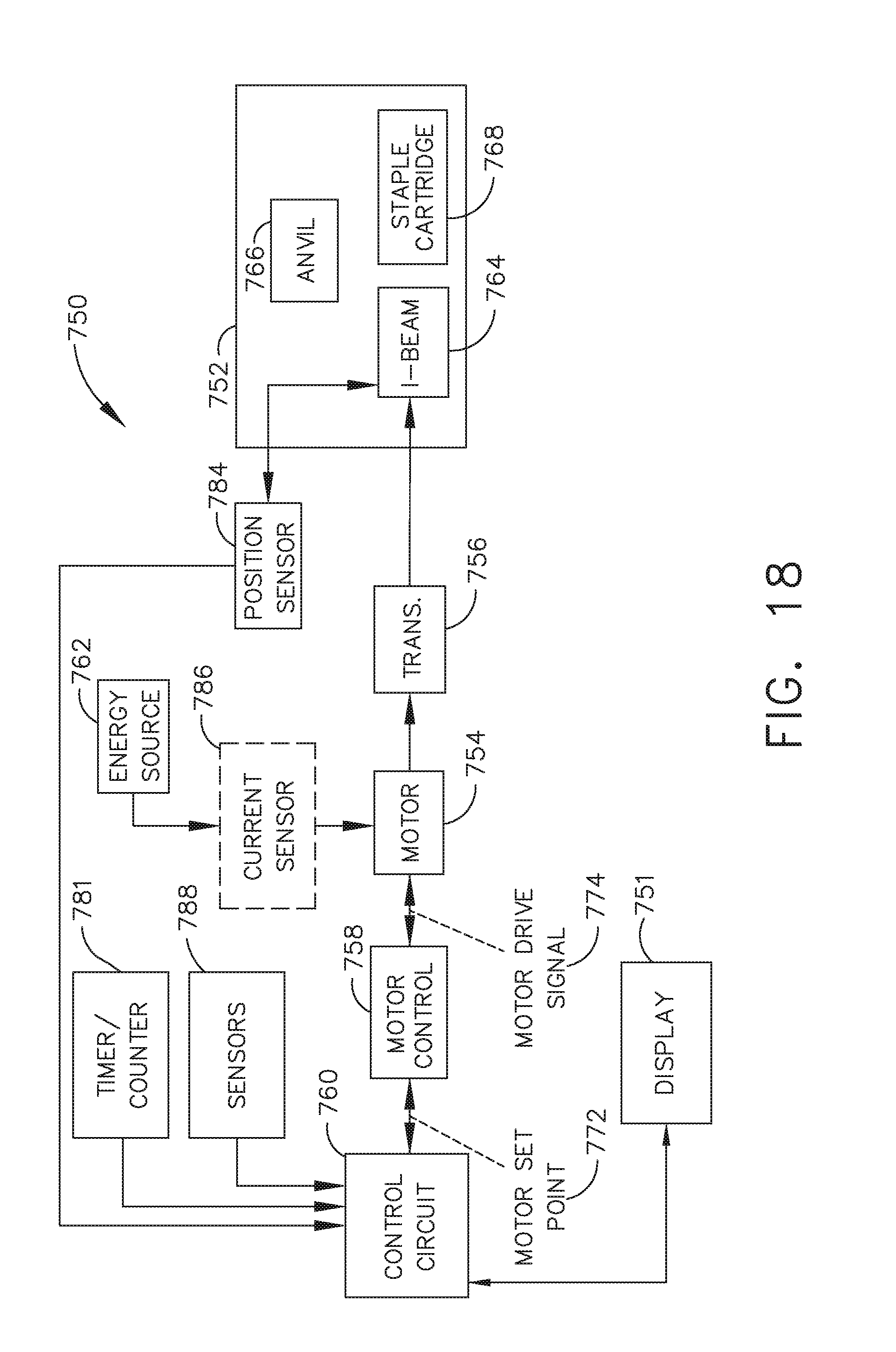
D00016
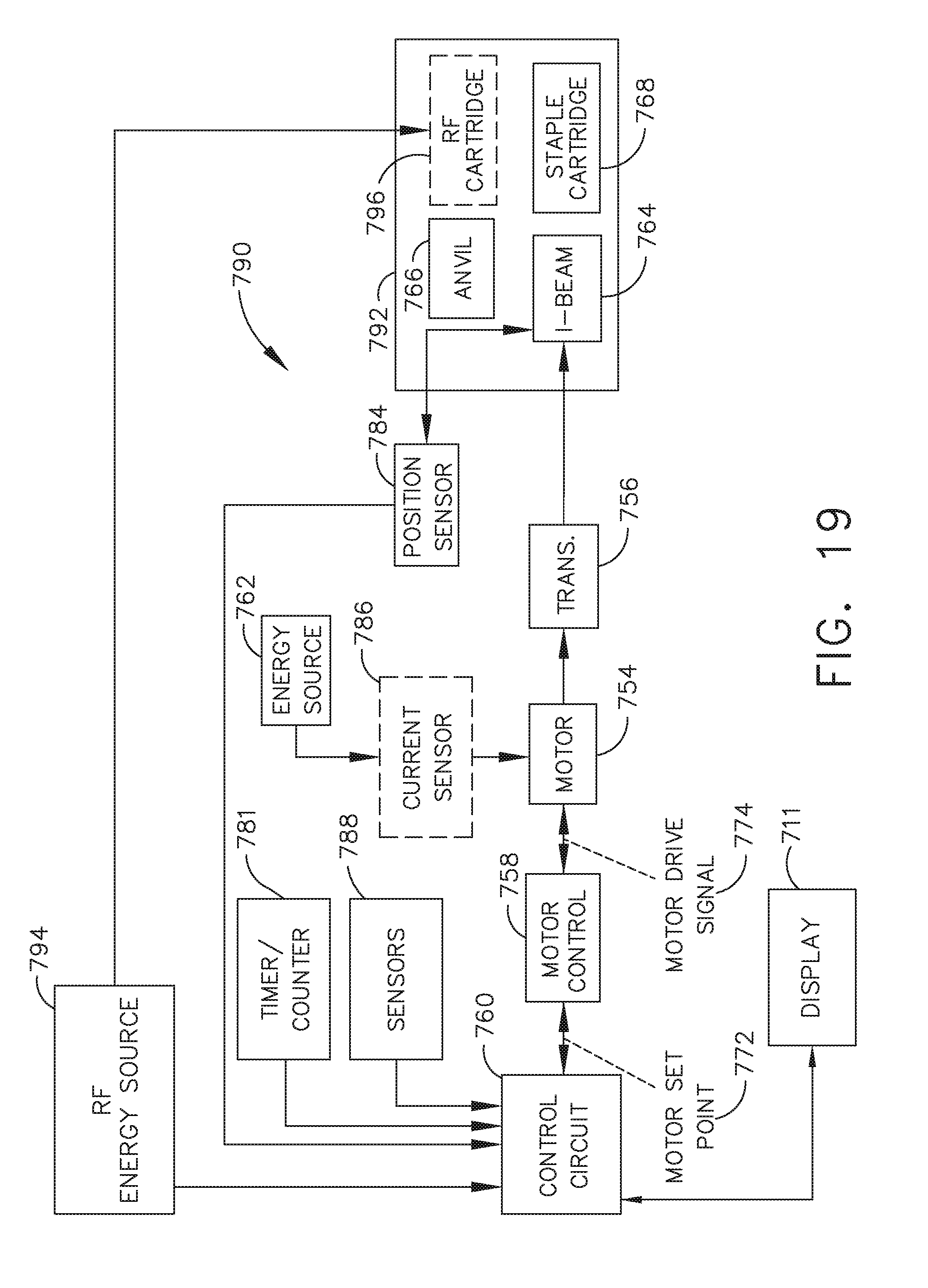
D00017
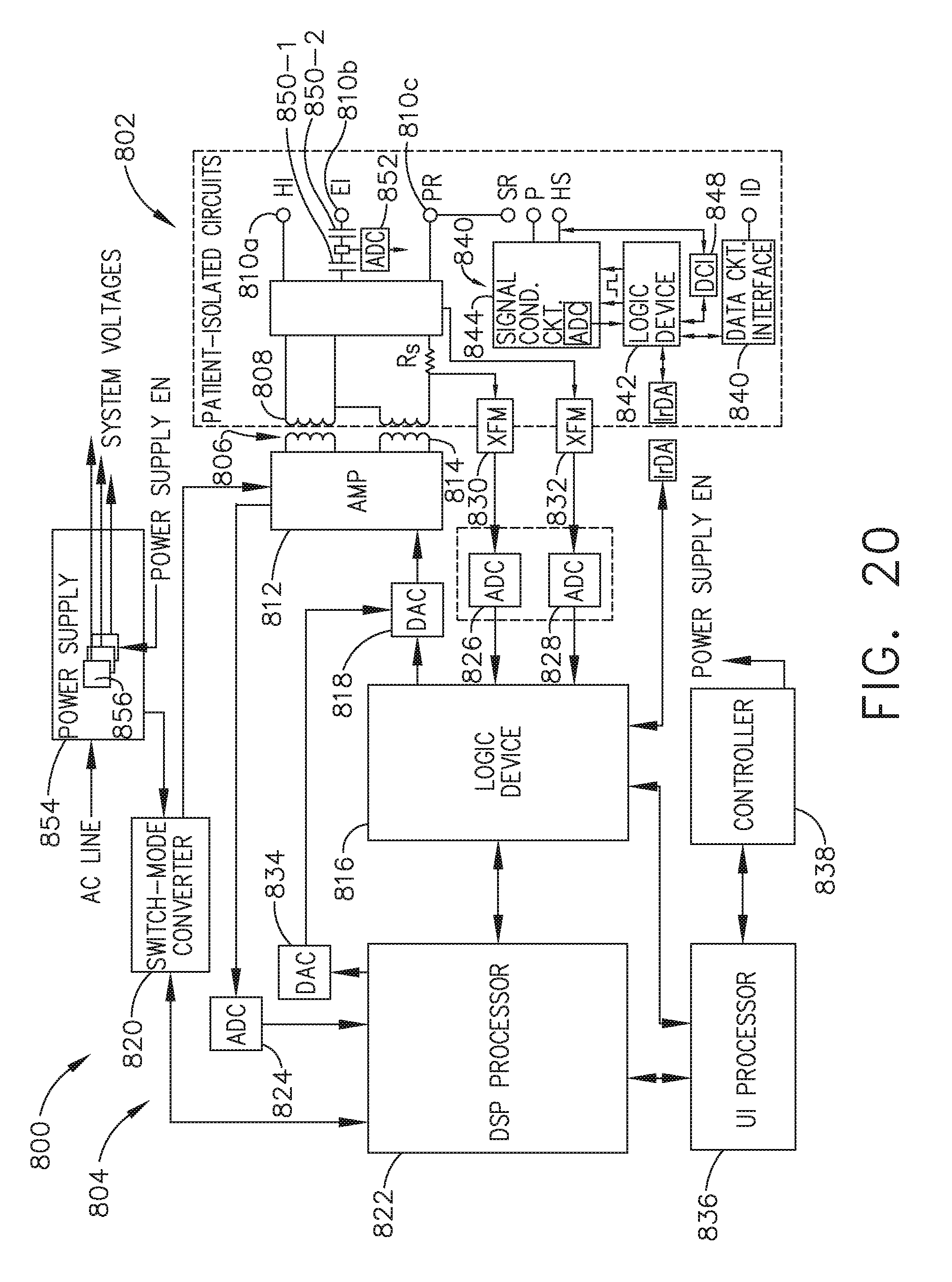
D00018
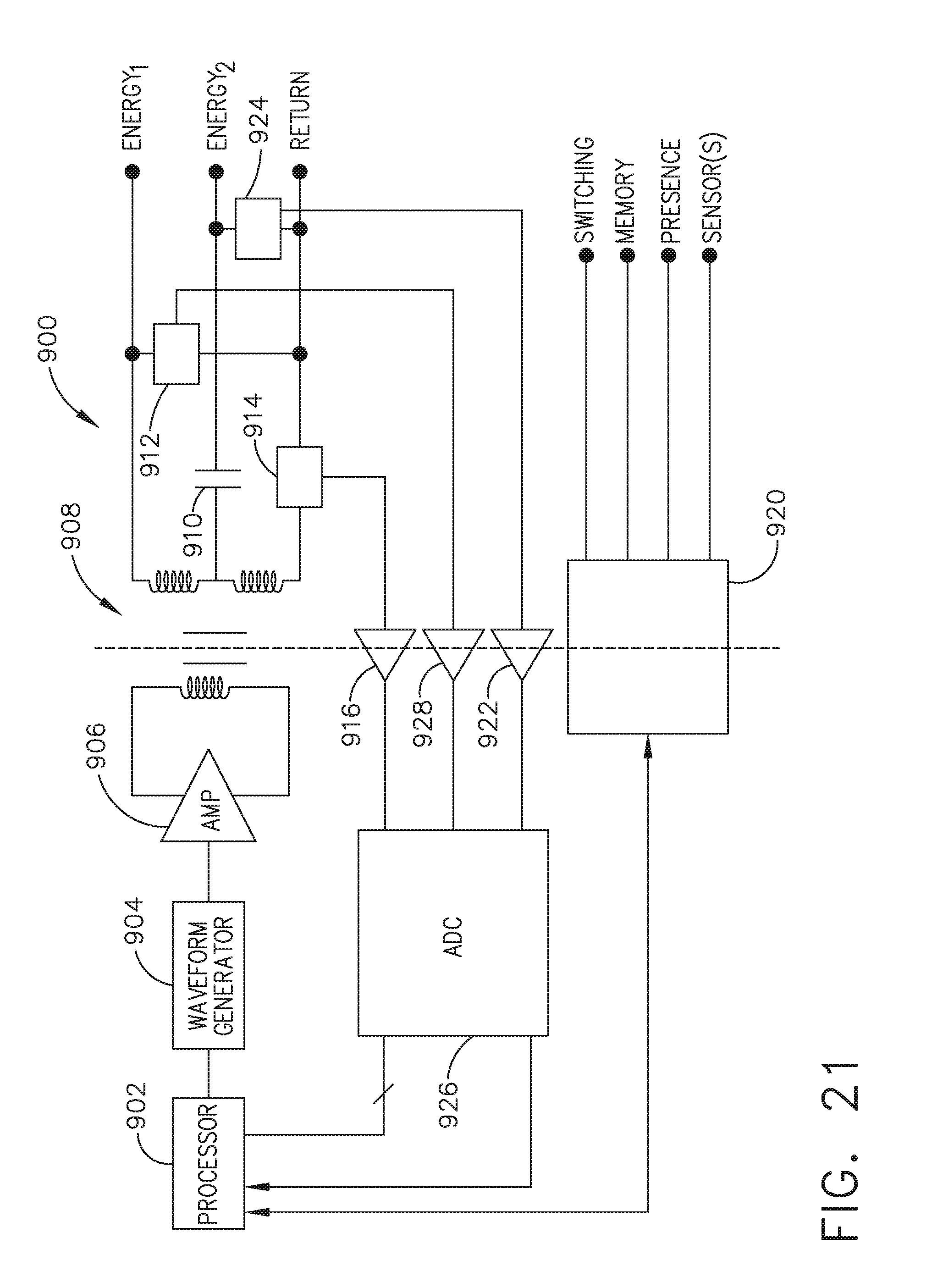
D00019
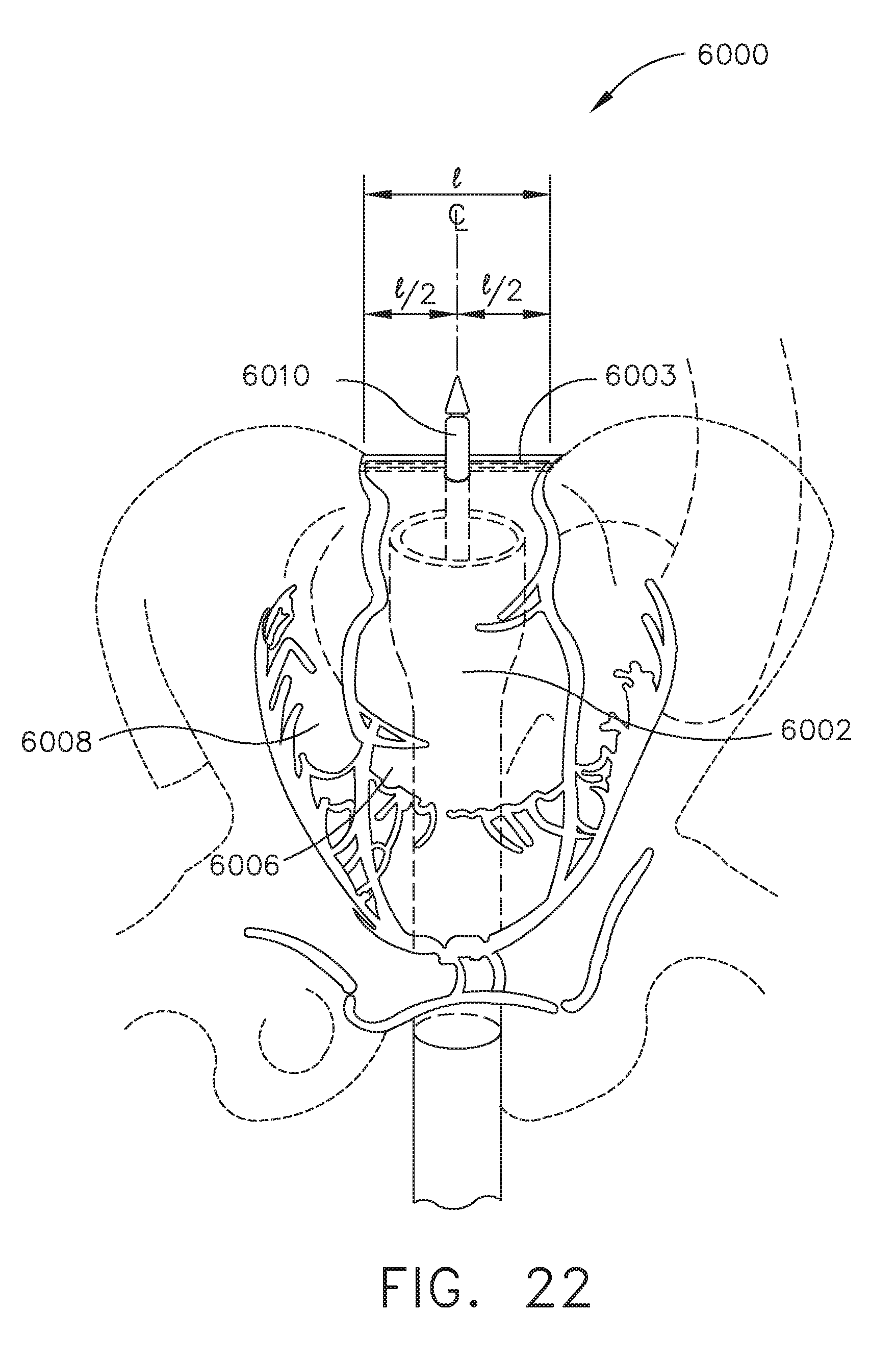
D00020
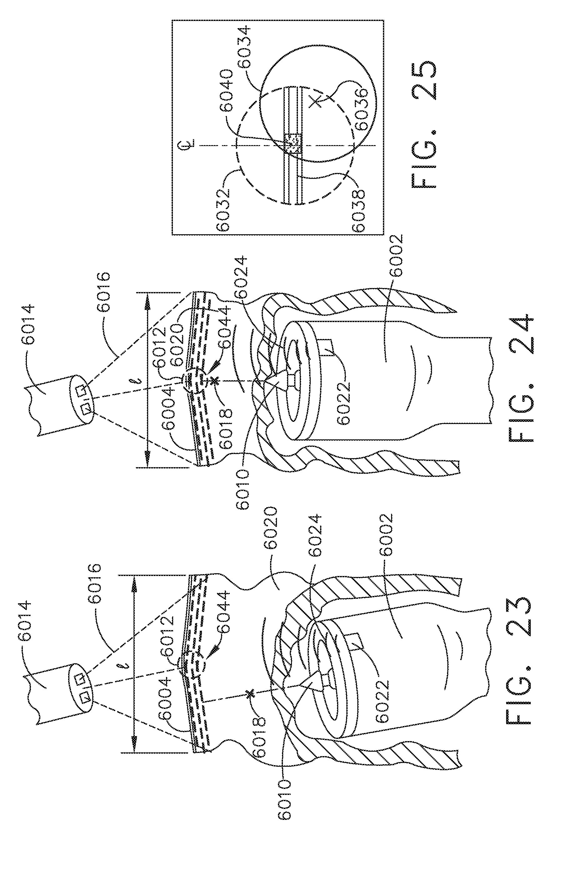
D00021

D00022

D00023

D00024

D00025
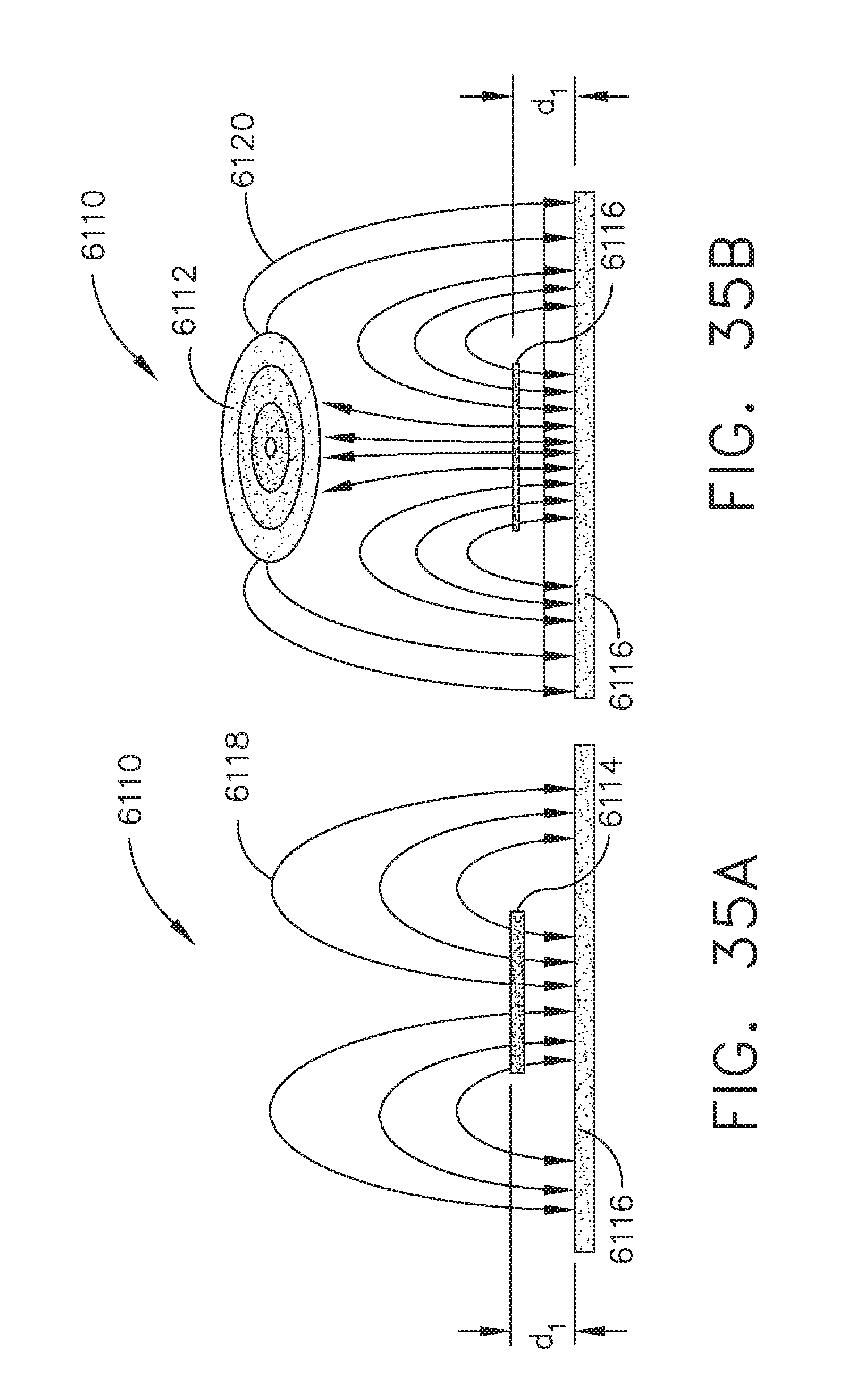
D00026
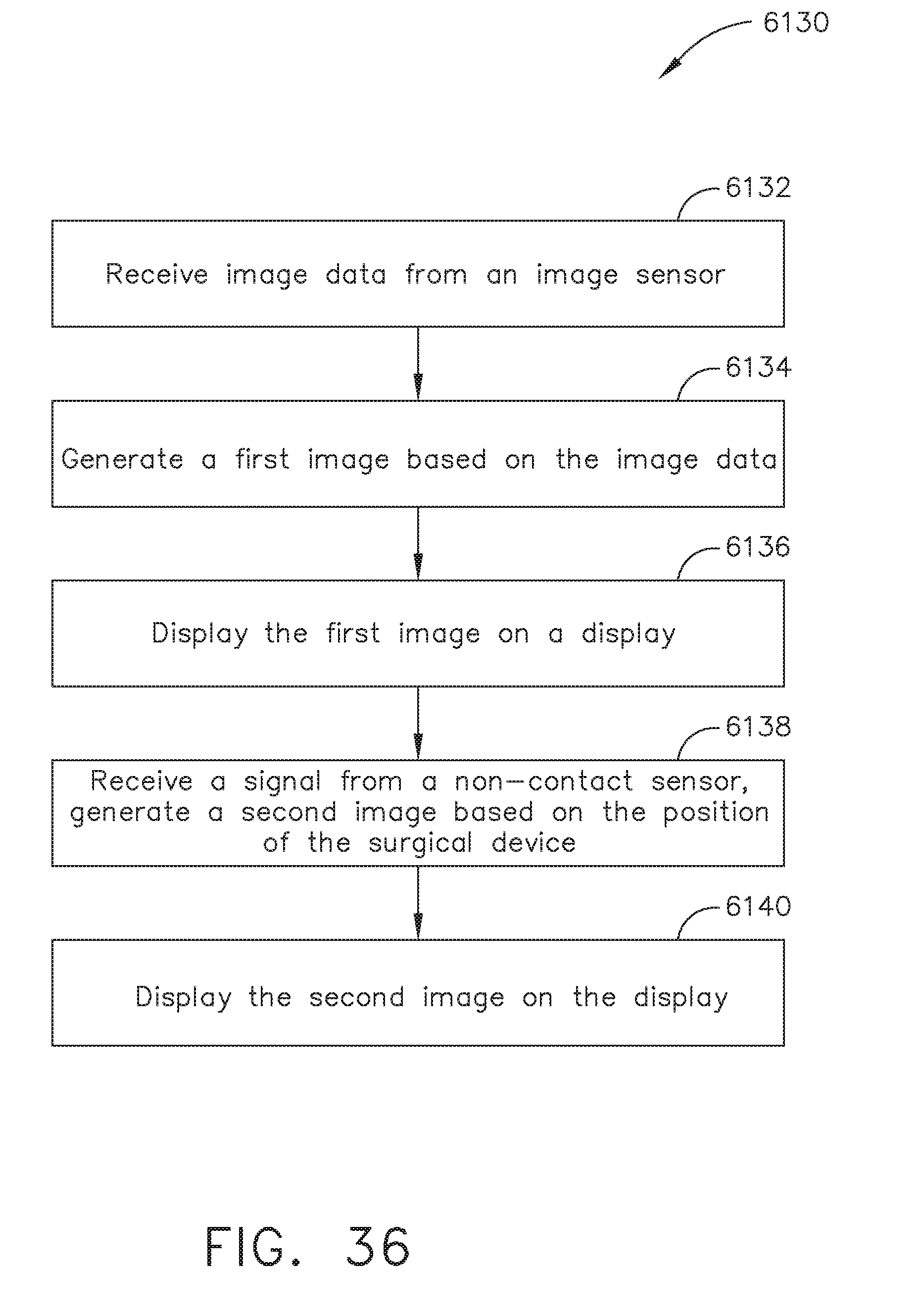
D00027

D00028

D00029

D00030

D00031
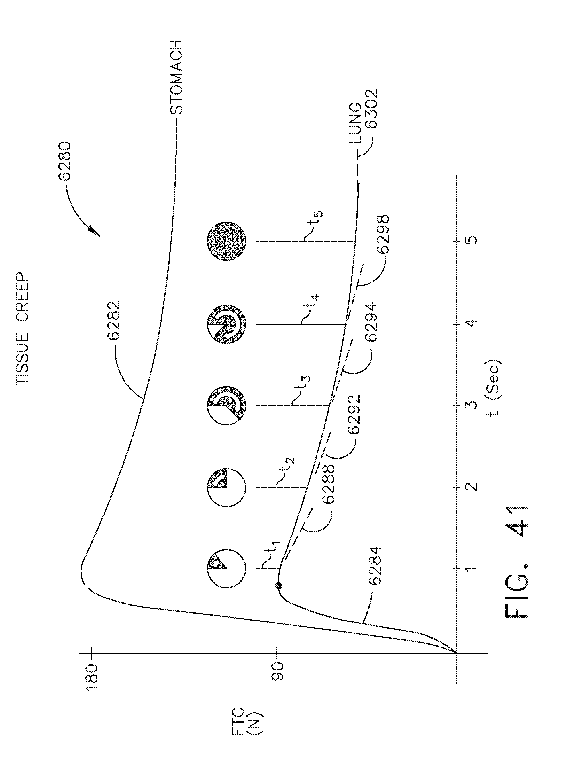
D00032

D00033

D00034

D00035

D00036

D00037

D00038

D00039

D00040

D00041

D00042

D00043
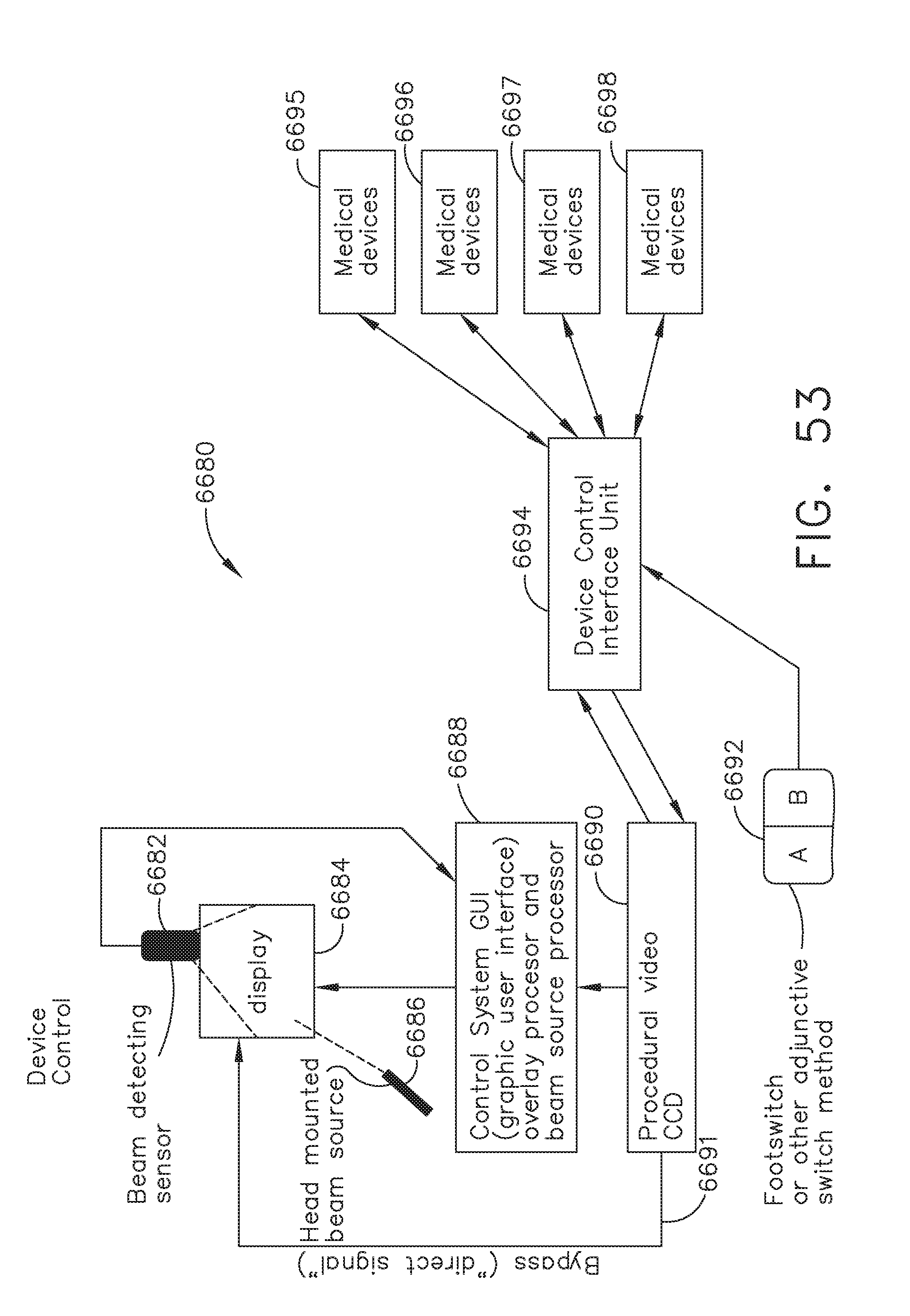
D00044
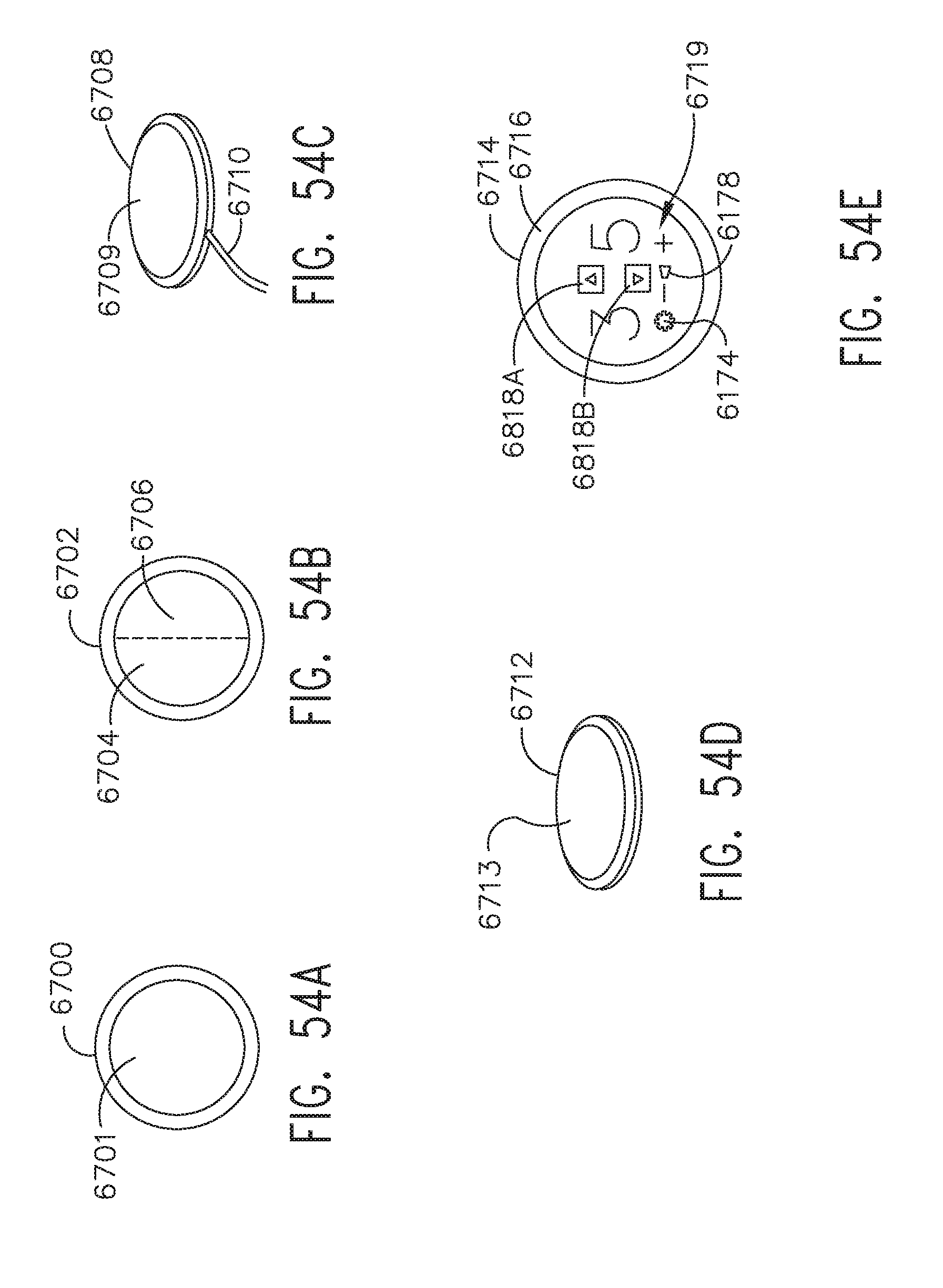
D00045

D00046
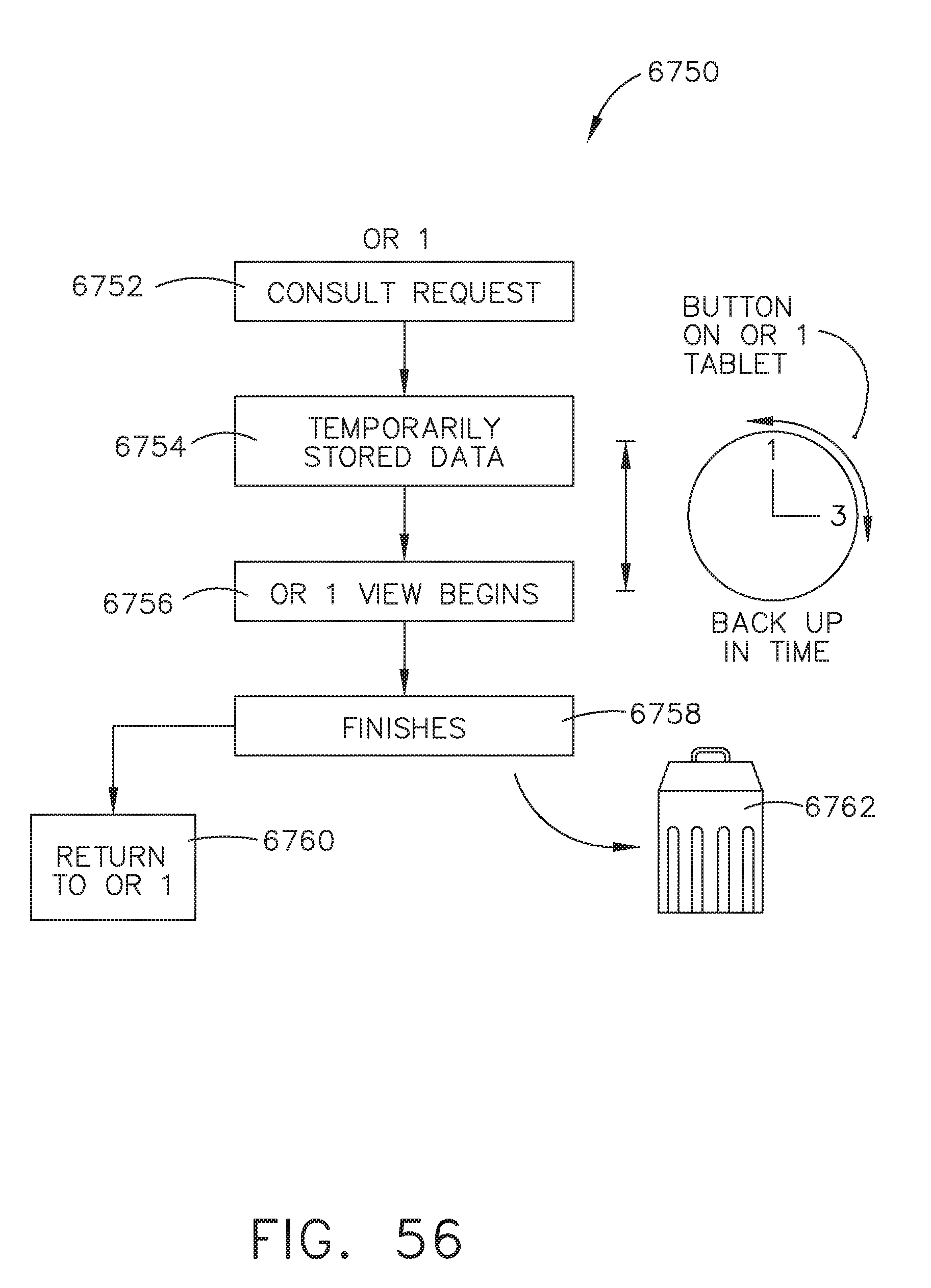
D00047

D00048

D00049

D00050
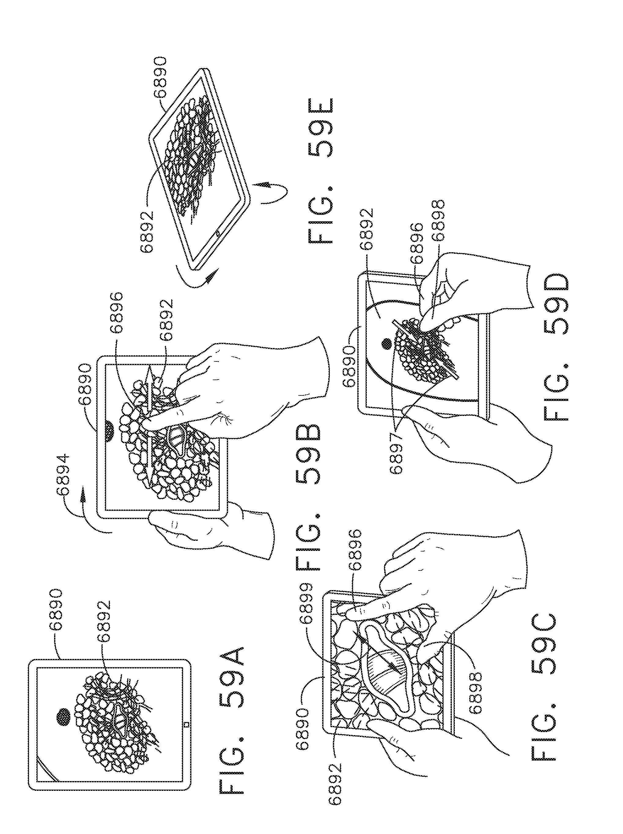
D00051

D00052

D00053

D00054

D00055

D00056

D00057

D00058
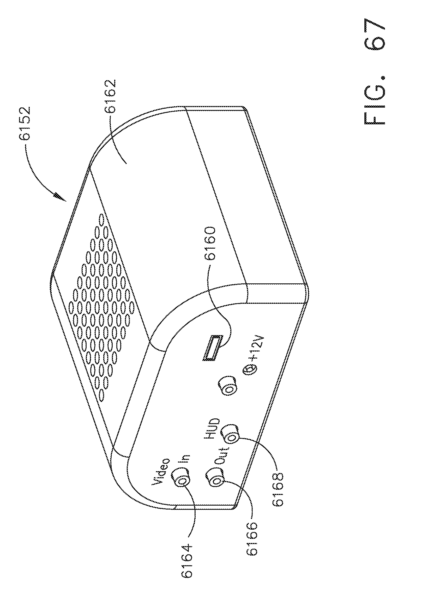
D00059

P00001

XML
uspto.report is an independent third-party trademark research tool that is not affiliated, endorsed, or sponsored by the United States Patent and Trademark Office (USPTO) or any other governmental organization. The information provided by uspto.report is based on publicly available data at the time of writing and is intended for informational purposes only.
While we strive to provide accurate and up-to-date information, we do not guarantee the accuracy, completeness, reliability, or suitability of the information displayed on this site. The use of this site is at your own risk. Any reliance you place on such information is therefore strictly at your own risk.
All official trademark data, including owner information, should be verified by visiting the official USPTO website at www.uspto.gov. This site is not intended to replace professional legal advice and should not be used as a substitute for consulting with a legal professional who is knowledgeable about trademark law.