Surgical System For Presenting Information Interpreted From External Data
Shelton, IV; Frederick E. ; et al.
U.S. patent application number 16/182230 was filed with the patent office on 2019-07-04 for surgical system for presenting information interpreted from external data. The applicant listed for this patent is Ethicon LLC. Invention is credited to Gregory J. Bakos, Jason L. Harris, Frederick E. Shelton, IV.
| Application Number | 20190200980 16/182230 |
| Document ID | / |
| Family ID | 68771325 |
| Filed Date | 2019-07-04 |

View All Diagrams
| United States Patent Application | 20190200980 |
| Kind Code | A1 |
| Shelton, IV; Frederick E. ; et al. | July 4, 2019 |
SURGICAL SYSTEM FOR PRESENTING INFORMATION INTERPRETED FROM EXTERNAL DATA
Abstract
A surgical instrument is disclosed. The surgical instrument includes an end effector, a user interface, and a control circuit. The end effector is configured to deploy staples into tissue grasped by the end effector and cut the grasped tissue during a firing stroke. The control circuit is configured to cause at least one parameter setting associated with the firing stroke to be displayed on the user interface and cause interpreted information relevant to the firing stroke to be displayed concurrently with the at least one parameter setting on the user interface, wherein the interpreted information is based on external data.
| Inventors: | Shelton, IV; Frederick E.; (Hillsboro, OH) ; Harris; Jason L.; (Lebanon, OH) ; Bakos; Gregory J.; (Mason, OH) | ||||||||||
| Applicant: |
|
||||||||||
|---|---|---|---|---|---|---|---|---|---|---|---|
| Family ID: | 68771325 | ||||||||||
| Appl. No.: | 16/182230 | ||||||||||
| Filed: | November 6, 2018 |
Related U.S. Patent Documents
| Application Number | Filing Date | Patent Number | ||
|---|---|---|---|---|
| 62729177 | Sep 10, 2018 | |||
| 62692747 | Jun 30, 2018 | |||
| 62692748 | Jun 30, 2018 | |||
| 62692768 | Jun 30, 2018 | |||
| 62659900 | Apr 19, 2018 | |||
| 62650898 | Mar 30, 2018 | |||
| 62650887 | Mar 30, 2018 | |||
| 62650882 | Mar 30, 2018 | |||
| 62650877 | Mar 30, 2018 | |||
| 62640417 | Mar 8, 2018 | |||
| 62640415 | Mar 8, 2018 | |||
| 62611341 | Dec 28, 2017 | |||
| 62611340 | Dec 28, 2017 | |||
| 62611339 | Dec 28, 2017 | |||
| Current U.S. Class: | 1/1 |
| Current CPC Class: | A61B 2017/00106 20130101; A61B 2018/00982 20130101; A61B 17/320068 20130101; A61B 2034/252 20160201; A61B 2017/00221 20130101; A61B 2017/07271 20130101; A61B 2017/00061 20130101; G16H 20/40 20180101; A61B 2218/002 20130101; A61B 2017/00075 20130101; A61B 17/072 20130101; A61B 2018/126 20130101; A61B 34/25 20160201; A61B 2034/2057 20160201; G16H 30/40 20180101; A61B 2017/00398 20130101; A61B 2034/302 20160201; A61B 2018/1253 20130101; A61B 2034/301 20160201; A61B 2034/2065 20160201; A61B 18/14 20130101; A61B 2017/00132 20130101; A61B 2218/008 20130101; A61B 2090/373 20160201; A61B 2017/00022 20130101; G16H 40/63 20180101; A61B 2018/00601 20130101; A61B 2017/00115 20130101; A61B 2017/00199 20130101; A61B 2017/07285 20130101; A61B 1/00087 20130101; A61B 2034/2074 20160201; A61B 90/361 20160201; A61B 2017/00057 20130101; A61B 2017/00044 20130101; G16H 40/60 20180101; A61B 2034/254 20160201; A61B 1/00183 20130101; A61B 2018/00994 20130101; A61B 2018/0063 20130101; A61B 2017/00809 20130101; A61B 17/07207 20130101; A61B 34/35 20160201; G06F 11/00 20130101; G16H 30/20 20180101 |
| International Class: | A61B 17/072 20060101 A61B017/072; A61B 34/35 20060101 A61B034/35; A61B 90/00 20060101 A61B090/00; A61B 18/14 20060101 A61B018/14; G16H 20/40 20060101 G16H020/40; G16H 40/63 20060101 G16H040/63 |
Claims
1. A surgical instrument, comprising: an end effector configured to deploy staples into tissue grasped by the end effector and cut the grasped tissue during a firing stroke; a user interface; and a control circuit, configured to: cause at least one parameter setting associated with the firing stroke to be displayed on the user interface; and cause interpreted information relevant to the firing stroke to be displayed concurrently with the at least one parameter setting on the user interface, wherein the interpreted information is based on external data.
2. The surgical instrument of claim 1, wherein the external data originated with a measurement device that is separate from the surgical instrument.
3. The surgical instrument of claim 1, wherein the external data is transmitted to the surgical instrument through a wireless communication link.
4. The surgical instrument of claim 1, wherein the interpreted information is updated in real time.
5. The surgical instrument of claim 1, wherein the interpreted information is updated at a predetermined update rate.
6. The surgical instrument of claim 1, wherein the interpreted information relates to tissue hemostasis.
7. The surgical instrument of claim 1, wherein the interpreted information relates to hemostasis of tissue previously treated with the end effector.
8. The surgical instrument of claim 1, wherein the interpreted information relates to blood pressure of a selected blood vessel.
9. The surgical instrument of claim 1, wherein the at least one parameter comprises a speed setting of the firing stroke.
10. The surgical instrument of claim 1, wherein the at least one parameter is a wait-time setting before beginning the firing stroke.
11. A surgical instrument, comprising: an end effector configured to deploy staples into tissue grasped by the end effector and cut the grasped tissue during a firing stroke; a user interface; and a control circuit, configured to: cause at least one parameter setting associated with the firing stroke to be displayed on the user interface; and cause interpreted information relevant to the firing stroke to be displayed concurrently with the at least one parameter setting on the user interface, wherein the interpreted information is based on imaging data.
12. The surgical instrument of claim 11, wherein the interpreted information is updated in real time.
13. The surgical instrument of claim 11, wherein the interpreted information is updated at a predetermined update rate.
14. The surgical instrument of claim 11, wherein the interpreted information relates to tissue hemostasis.
15. The surgical instrument of claim 11, wherein the interpreted information relates to hemostasis of tissue previously treated with the end effector.
16. The surgical instrument of claim 11, wherein the interpreted information relates to blood pressure of a selected blood vessel.
17. The surgical instrument of claim 11, wherein the at least one parameter setting comprises a speed setting of the firing stroke.
18. The surgical instrument of claim 11, wherein the at least one parameter setting is a wait-time setting before beginning the firing stroke.
19. A surgical instrument, comprising: an end effector configured to perform a function to treat tissue grasped by the end effector; a user interface; and a control circuit, configured to: cause at least one parameter setting associated with the function to be displayed on the user interface; and cause interpreted information relevant to the function to be displayed concurrently with the at least one parameter setting on the user interface, wherein the interpreted information is based on external data.
20. The surgical instrument of claim 19, wherein the external data originated with a measurement device that is separate from the surgical instrument.
Description
CROSS-REFERENCE TO RELATED APPLICATIONS
[0001] The present application claims priority under 35 U.S.C. .sctn. 119(e) to U.S. Provisional Patent Application No. 62/729,177, titled AUTOMATED DATA SCALING, ALIGNMENT, AND ORGANIZING BASED ON PREDEFINED PARAMETERS WITHIN A SURGICAL NETWORK BEFORE TRANSMISSION, filed on Sep. 10, 2018, the disclosure of which is herein incorporated by reference in its entirety.
[0002] The present application also claims priority under 35 U.S.C. .sctn. 119(e) to U.S. Provisional Patent Application No. 62/692,747, titled SMART ACTIVATION OF AN ENERGY DEVICE BY ANOTHER DEVICE, filed on Jun. 30, 2018, to U.S. Provisional Patent Application No. 62/692,748, titled SMART ENERGY ARCHITECTURE, filed on Jun. 30, 2018, and to U.S. Provisional Patent Application No. 62/692,768, titled SMART ENERGY DEVICES, filed on Jun. 30, 2018, the disclosure of each of which is herein incorporated by reference in its entirety.
[0003] The present application also claims priority under 35 U.S.C. .sctn. 119(e) to U.S. Provisional Patent Application No. 62/659,900, titled METHOD OF HUB COMMUNICATION, filed on Apr. 19, 2018, the disclosure of each of which is herein incorporated by reference in its entirety.
[0004] The present application also claims priority under 35 U.S.C. .sctn. 119(e) to U.S. Provisional Patent Application No. 62/650,898 filed on Mar. 30, 2018, titled CAPACITIVE COUPLED RETURN PATH PAD WITH SEPARABLE ARRAY ELEMENTS, to U.S. Provisional Patent Application Ser. No. 62/650,887, titled SURGICAL SYSTEMS WITH OPTIMIZED SENSING CAPABILITIES, filed Mar. 30, 2018, to U.S. Provisional Patent Application Ser. No. 62/650,882, titled SMOKE EVACUATION MODULE FOR INTERACTIVE SURGICAL PLATFORM, filed Mar. 30, 2018, and to U.S. Provisional Patent Application Ser. No. 62/650,877, titled SURGICAL SMOKE EVACUATION SENSING AND CONTROLS, filed Mar. 30, 2018, the disclosure of each of which is herein incorporated by reference in its entirety.
[0005] The present application also claims priority under 35 U.S.C. .sctn. 119(e) to U.S. Provisional Patent Application Ser. No. 62/640,417, titled TEMPERATURE CONTROL IN ULTRASONIC DEVICE AND CONTROL SYSTEM THEREFOR, filed Mar. 8, 2018, and to U.S. Provisional Patent Application Ser. No. 62/640,415, titled ESTIMATING STATE OF ULTRASONIC END EFFECTOR AND CONTROL SYSTEM THEREFOR, filed Mar. 8, 2018, the disclosure of each of which is herein incorporated by reference in its entirety.
[0006] The present application also claims priority under 35 U.S.C. .sctn. 119(e) to U.S. Provisional Patent Application Ser. No. 62/611,341, titled INTERACTIVE SURGICAL PLATFORM, filed Dec. 28, 2017, to U.S. Provisional Patent Application Ser. No. 62/611,340, titled CLOUD-BASED MEDICAL ANALYTICS, filed Dec. 28, 2017, and to U.S. Provisional Patent Application Ser. No. 62/611,339, titled ROBOT ASSISTED SURGICAL PLATFORM, filed Dec. 28, 2017, the disclosure of each of which is herein incorporated by reference in its entirety.
BACKGROUND
[0007] The present disclosure relates to various surgical systems. Surgical procedures are typically performed in surgical operating theaters or rooms in a healthcare facility such as, for example, a hospital. A sterile field is typically created around the patient. The sterile field may include the scrubbed team members, who are properly attired, and all furniture and fixtures in the area. Various surgical devices and systems are utilized in performance of a surgical procedure.
[0008] Furthermore, in the Digital and Information Age, medical systems and facilities are often slower to implement systems or procedures utilizing newer and improved technologies due to patient safety and a general desire for maintaining traditional practices. However, often times medical systems and facilities may lack communication and shared knowledge with other neighboring or similarly situated facilities as a result. To improve patient practices, it would be desirable to find ways to help interconnect medical systems and facilities better.
SUMMARY
[0009] In various embodiments, a surgical instrument is disclosed that includes an end effector, a user interface, and a control circuit. The end effector is configured to deploy staples into tissue grasped by the end effector and cut the grasped tissue during a firing stroke. The control circuit is configured to cause at least one parameter setting associated with the firing stroke to be displayed on the user interface and cause interpreted information relevant to the firing stroke to be displayed concurrently with the at least one parameter setting on the user interface, wherein the interpreted information is based on external data.
[0010] In various embodiments, a surgical instrument is disclosed that includes an end effector, a user interface, and a control circuit. The end effector is configured to deploy staples into tissue grasped by the end effector and cut the grasped tissue during a firing stroke. The control circuit is configured to cause at least one parameter setting associated with the firing stroke to be displayed on the user interface and cause interpreted information relevant to the firing stroke to be displayed concurrently with the at least one parameter setting on the user interface, wherein the interpreted information is based on imaging data.
[0011] In various embodiments, a surgical instrument is disclosed that includes an end effector, a user interface, and a control circuit. The end effector is configured to perform a function to treat tissue grasped by the end effector. The control circuit is configured to cause at least one parameter setting associated with the function to be displayed on the user interface and cause interpreted information relevant to the function to be displayed concurrently with the at least one parameter setting on the user interface, wherein the interpreted information is based on external data.
FIGURES
[0012] The various aspects described herein, both as to organization and methods of operation, together with further objects and advantages thereof, may best be understood by reference to the following description, taken in conjunction with the accompanying drawings as follows.
[0013] FIG. 1 is a block diagram of a computer-implemented interactive surgical system, in accordance with at least one aspect of the present disclosure.
[0014] FIG. 2 is a surgical system being used to perform a surgical procedure in an operating room, in accordance with at least one aspect of the present disclosure.
[0015] FIG. 3 is a surgical hub paired with a visualization system, a robotic system, and an intelligent instrument, in accordance with at least one aspect of the present disclosure.
[0016] FIG. 4 is a partial perspective view of a surgical hub enclosure, and of a combo generator module slidably receivable in a drawer of the surgical hub enclosure, in accordance with at least one aspect of the present disclosure.
[0017] FIG. 5 is a perspective view of a combo generator module with bipolar, ultrasonic, and monopolar contacts and a smoke evacuation component, in accordance with at least one aspect of the present disclosure.
[0018] FIG. 6 illustrates individual power bus attachments for a plurality of lateral docking ports of a lateral modular housing configured to receive a plurality of modules, in accordance with at least one aspect of the present disclosure.
[0019] FIG. 7 illustrates a vertical modular housing configured to receive a plurality of modules, in accordance with at least one aspect of the present disclosure.
[0020] FIG. 8 illustrates a surgical data network comprising a modular communication hub configured to connect modular devices located in one or more operating theaters of a healthcare facility, or any room in a healthcare facility specially equipped for surgical operations, to the cloud, in accordance with at least one aspect of the present disclosure.
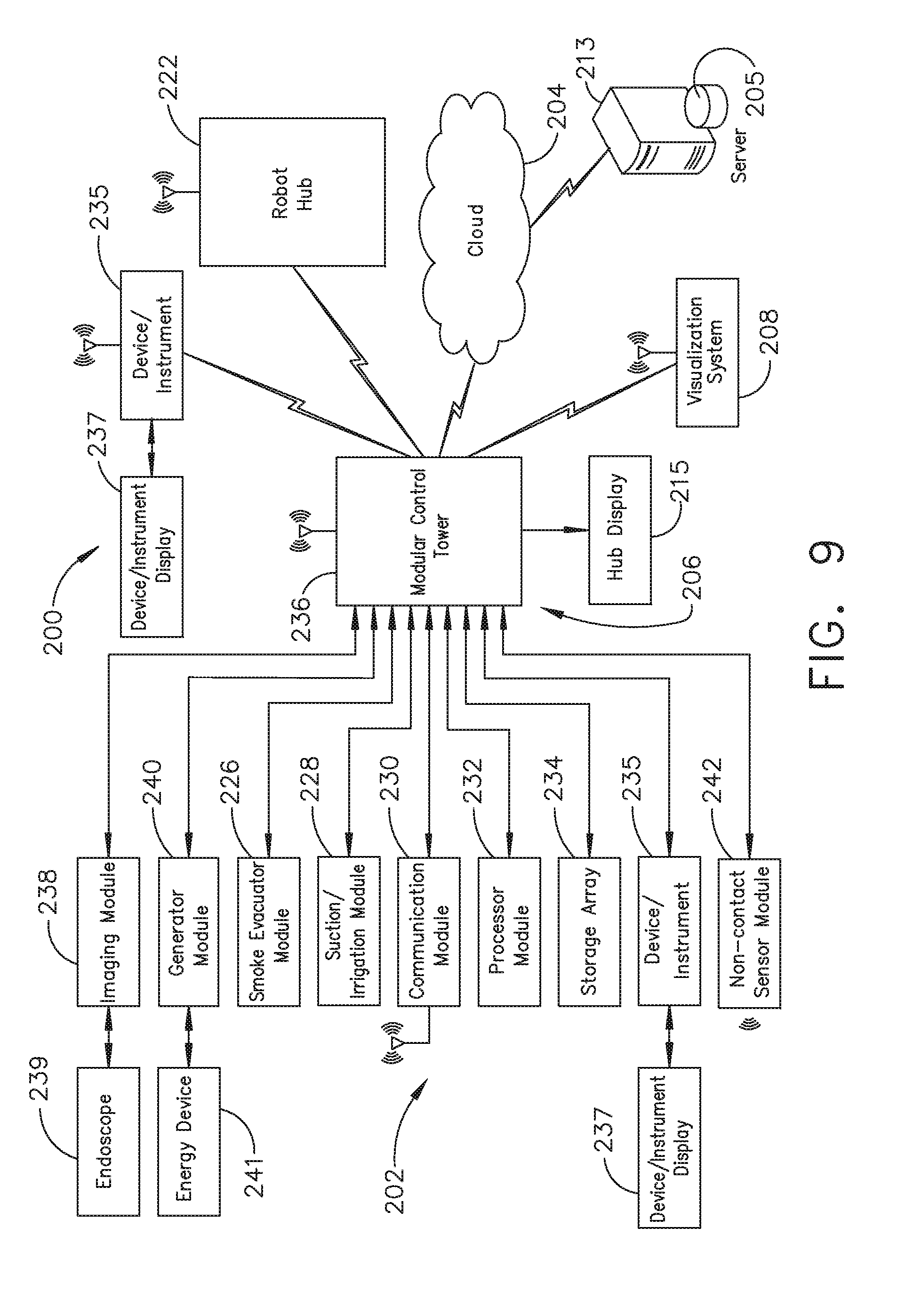
[0021] FIG. 9 illustrates a computer-implemented interactive surgical system, in accordance with at least one aspect of the present disclosure.
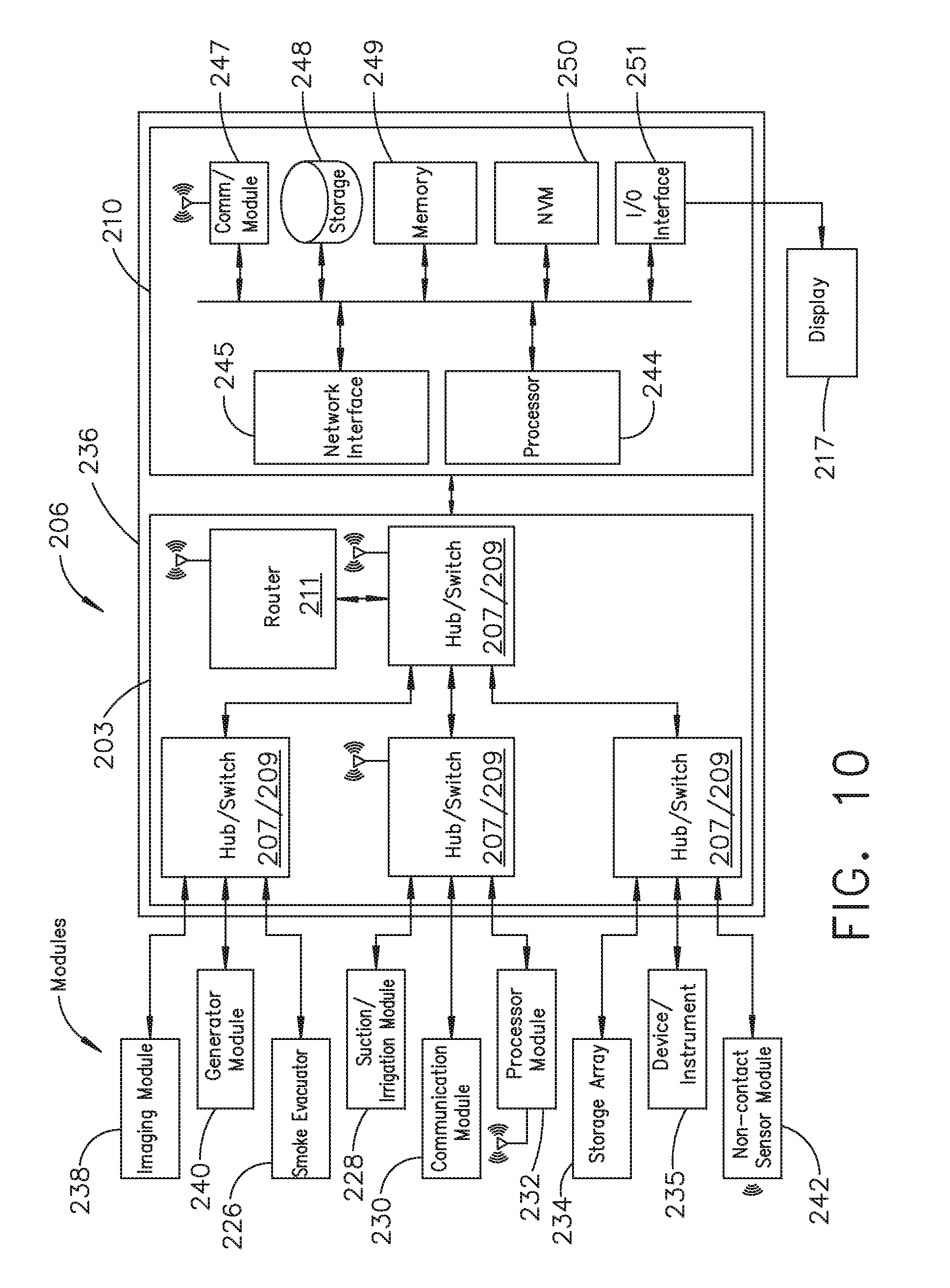
[0022] FIG. 10 illustrates a surgical hub comprising a plurality of modules coupled to the modular control tower, in accordance with at least one aspect of the present disclosure.
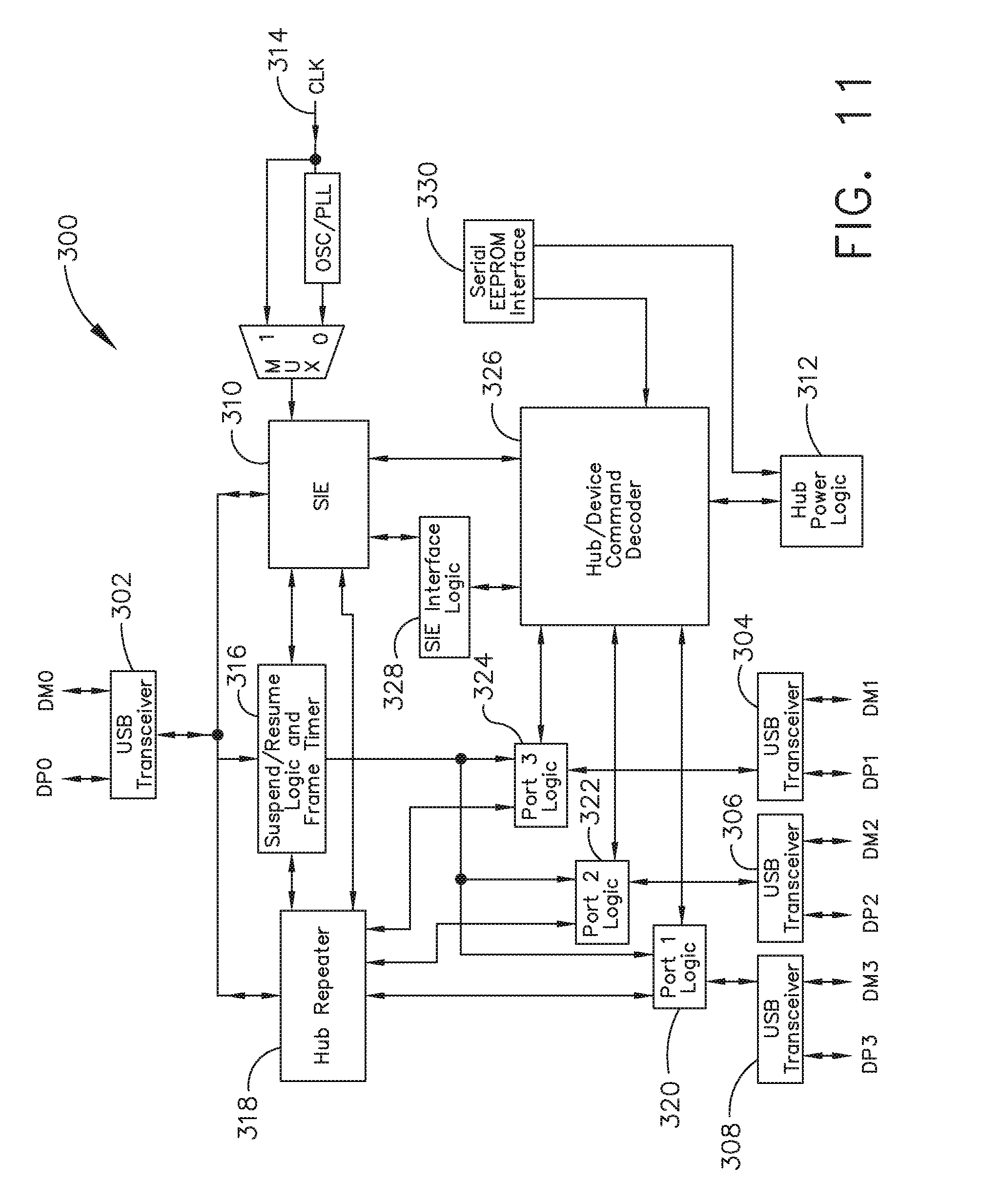
[0023] FIG. 11 illustrates one aspect of a Universal Serial Bus (USB) network hub device, in accordance with at least one aspect of the present disclosure.
[0024] FIG. 12 is a block diagram of a cloud computing system comprising a plurality of smart surgical instruments coupled to surgical hubs that may connect to the cloud component of the cloud computing system, in accordance with at least one aspect of the present disclosure.
[0025] FIG. 13 is a functional module architecture of a cloud computing system, in accordance with at least one aspect of the present disclosure.
[0026] FIG. 14 illustrates a diagram of a situationally aware surgical system, in accordance with at least one aspect of the present disclosure.
[0027] FIG. 15 is a timeline depicting situational awareness of a surgical hub, in accordance with at least one aspect of the present disclosure.
[0028] FIG. 16 illustrates a surgical device including a user interface and a surgical stapling end effector, in accordance with at least one aspect of the present disclosure.
[0029] FIG. 17 is a schematic diagram of various components of the surgical device of Claim 16.
[0030] FIG. 18 is a logic flow diagram of a process depicting a control program or a logic configuration for displaying interpreted information based on external data, in accordance with at least one aspect of the present disclosure.
[0031] FIG. 19 is a logic flow diagram of a process depicting a control program or a logic configuration for displaying interpreted information based on external data, in accordance with at least one aspect of the present disclosure.
[0032] FIG. 20 illustrates a surgical device including a user interface and a surgical stapling end effector, in accordance with at least one aspect of the present disclosure.
[0033] FIG. 21 is a logic flow diagram of a process depicting a control program or a logic configuration for adjusting a parameter setting of the surgical device of FIG. 20, in accordance with at least one aspect of the present disclosure.
[0034] FIG. 22 is a logic flow diagram of a process depicting a control program or a logic configuration for adjusting a parameter setting of the surgical device of FIG. 20, in accordance with at least one aspect of the present disclosure.
[0035] FIG. 23 illustrates a surgical device including a user interface and a surgical stapling end effector, in accordance with at least one aspect of the present disclosure.
[0036] FIG. 24 is a logic flow diagram of a process depicting a control program or a logic configuration for automatically adjusting a field of view of a medical imaging device with respect to a detected critical structure, in accordance with at least one aspect of the present disclosure.
[0037] FIG. 25 is a logic flow diagram of a process depicting a control program or a logic configuration for obtaining user permission to automatically adjust a field of view of a medical imaging device with respect to a critical structure, in accordance with at least one aspect of the present disclosure.
DESCRIPTION
[0038] Applicant of the present application owns the following U.S. patent applications, filed on Nov. 6, 2018, the disclosure of each of which is herein incorporated by reference in its entirety: [0039] U.S. patent application Ser. No. ______, titled SURGICAL NETWORK, INSTRUMENT, AND CLOUD RESPONSES BASED ON VALIDATION OF RECEIVED DATASET AND AUTHENTICATION OF ITS SOURCE AND INTEGRITY, Attorney Docket No. END9012USNP1/180511-1; [0040] U.S. patent application Ser. No. ______, titled MODIFICATION OF SURGICAL SYSTEMS CONTROL PROGRAMS BASED ON MACHINE LEARNING, Attorney Docket No. END9012USNP3/180511-3; [0041] U.S. patent application Ser. No. ______, titled ADJUSTMENT OF DEVICE CONTROL PROGRAMS BASED ON STRATIFIED CONTEXTUAL DATA IN ADDITION TO THE DATA, Attorney Docket No. END9012USNP4/180511-4; [0042] U.S. patent application Ser. No. ______, titled SURGICAL HUB AND MODULAR DEVICE RESPONSE ADJUSTMENT BASED ON SITUATIONAL AWARENESS, Attorney Docket No. END9012USNP5/180511-5; [0043] U.S. patent application Ser. No. ______, titled DETECTION AND ESCALATION OF SECURITY RESPONSES OF SURGICAL INSTRUMENTS TO INCREASING SEVERITY THREATS, Attorney Docket No. END9012USNP6/180511-6; [0044] U.S. patent application Ser. No. ______, titled INTERACTIVE SURGICAL SYSTEM, Attorney Docket No. END9012USNP7/180511-7; [0045] U.S. patent application Ser. No. ______, titled AUTOMATED DATA SCALING, ALIGNMENT, AND ORGANIZING BASED ON PREDEFINED PARAMETERS WITHIN SURGICAL NETWORKS, Attorney Docket No. END9012USNP8/180511-8; [0046] U.S. patent application Ser. No. ______, titled SENSING THE PATIENT POSITION AND CONTACT UTILIZING THE MONO-POLAR RETURN PAD ELECTRODE TO PROVIDE SITUATIONAL AWARENESS TO A SURGICAL NETWORK, Attorney Docket No. END9013USNP1/180512-1; [0047] U.S. patent application Ser. No. ______, titled POWERED SURGICAL TOOL WITH PREDEFINED ADJUSTABLE CONTROL ALGORITHM FOR CONTROLLING END EFFECTOR PARAMETER, Attorney Docket No. END9014USNP1/180513-1; [0048] U.S. patent application Ser. No. ______, titled ADJUSTMENTS BASED ON AIRBORNE PARTICLE PROPERTIES, Attorney Docket No. END9016USNP1/180515-1; [0049] U.S. patent application Ser. No. ______, titled ADJUSTMENT OF A SURGICAL DEVICE FUNCTION BASED ON SITUATIONAL AWARENESS, Attorney Docket No. END9016USNP2/180515-2; [0050] U.S. patent application Ser. No. ______, titled REAL-TIME ANALYSIS OF COMPREHENSIVE COST OF ALL INSTRUMENTATION USED IN SURGERY UTILIZING DATA FLUIDITY TO TRACK INSTRUMENTS THROUGH STOCKING AND IN-HOUSE PROCESSES, Attorney Docket No. END9018USNP1/180517-1; [0051] U.S. patent application Ser. No. ______, titled USAGE AND TECHNIQUE ANALYSIS OF SURGEON/STAFF PERFORMANCE AGAINST A BASELINE TO OPTIMIZE DEVICE UTILIZATION AND PERFORMANCE FOR BOTH CURRENT AND FUTURE PROCEDURES, Attorney Docket No. END9018USNP2/180517-2; [0052] U.S. patent application Ser. No. ______, titled IMAGE CAPTURING OF THE AREAS OUTSIDE THE ABDOMEN TO IMPROVE PLACEMENT AND CONTROL OF A SURGICAL DEVICE IN USE, Attorney Docket No. END9018USNP3/180517-3; [0053] U.S. patent application Ser. No. ______, titled COMMUNICATION OF DATA WHERE A SURGICAL NETWORK IS USING CONTEXT OF THE DATA AND REQUIREMENTS OF A RECEIVING SYSTEM/USER TO INFLUENCE INCLUSION OR LINKAGE OF DATA AND METADATA TO ESTABLISH CONTINUITY, Attorney Docket No. END9018USNP4/180517-4; [0054] U.S. patent application Ser. No. ______, titled SURGICAL NETWORK RECOMMENDATIONS FROM REAL TIME ANALYSIS OF PROCEDURE VARIABLES AGAINST A BASELINE HIGHLIGHTING DIFFERENCES FROM THE OPTIMAL SOLUTION, Attorney Docket No. END9018USNP5/180517-5; [0055] U.S. patent application Ser. No. ______, titled CONTROL OF A SURGICAL SYSTEM THROUGH A SURGICAL BARRIER, Attorney Docket No. END9019USNP1/180518-1; [0056] U.S. patent application Ser. No. ______, titled SURGICAL NETWORK DETERMINATION OF PRIORITIZATION OF COMMUNICATION, INTERACTION, OR PROCESSING BASED ON SYSTEM OR DEVICE NEEDS, Attorney Docket No. END9032USNP1/180519-1; [0057] U.S. patent application Ser. No. ______, titled WIRELESS PAIRING OF A SURGICAL DEVICE WITH ANOTHER DEVICE WITHIN A STERILE SURGICAL FIELD BASED ON THE USAGE AND SITUATIONAL AWARENESS OF DEVICES, Attorney Docket No. END9032USNP2/180519-2; [0058] U.S. patent application Ser. No. ______, titled ADJUSTMENT OF STAPLE HEIGHT OF AT LEAST ONE ROW OF STAPLES BASED ON THE SENSED TISSUE THICKNESS OR FORCE IN CLOSING, Attorney Docket No. END9034USNP1/180521-1; [0059] U.S. patent application Ser. No. ______, titled STAPLING DEVICE WITH BOTH COMPULSORY AND DISCRETIONARY LOCKOUTS BASED ON SENSED PARAMETERS, Attorney Docket No. END9034USNP2/180521-2; [0060] U.S. patent application Ser. No. ______, titled POWERED STAPLING DEVICE CONFIGURED TO ADJUST FORCE, ADVANCEMENT SPEED, AND OVERALL STROKE OF CUTTING MEMBER BASED ON SENSED PARAMETER OF FIRING OR CLAMPING, Attorney Docket No. END9034USNP3/180521-3; [0061] U.S. patent application Ser. No. ______, titled VARIATION OF RADIO FREQUENCY AND ULTRASONIC POWER LEVEL IN COOPERATION WITH VARYING CLAMP ARM PRESSURE TO ACHIEVE PREDEFINED HEAT FLUX OR POWER APPLIED TO TISSUE, Attorney Docket No. END9035USNP1/180522-1; and [0062] U.S. patent application Ser. No. ______, titled ULTRASONIC ENERGY DEVICE WHICH VARIES PRESSURE APPLIED BY CLAMP ARM TO PROVIDE THRESHOLD CONTROL PRESSURE AT A CUT PROGRESSION LOCATION, Attorney Docket No. END9035USNP2/180522-2.
[0063] Applicant of the present application owns the following U.S. patent applications, filed on Sep. 10, 2018, the disclosure of each of which is herein incorporated by reference in its entirety: [0064] U.S. Provisional Patent Application No. 62/729,183, titled A CONTROL FOR A SURGICAL NETWORK OR SURGICAL NETWORK CONNECTED DEVICE THAT ADJUSTS ITS FUNCTION BASED ON A SENSED SITUATION OR USAGE; [0065] U.S. Provisional Patent Application No. 62/729,177, titled AUTOMATED DATA SCALING, ALIGNMENT, AND ORGANIZING BASED ON PREDEFINED PARAMETERS WITHIN A SURGICAL NETWORK BEFORE TRANSMISSION; [0066] U.S. Provisional Patent Application No. 62/729,176, titled INDIRECT COMMAND AND CONTROL OF A FIRST OPERATING ROOM SYSTEM THROUGH THE USE OF A SECOND OPERATING ROOM SYSTEM WITHIN A STERILE FIELD WHERE THE SECOND OPERATING ROOM SYSTEM HAS PRIMARY AND SECONDARY OPERATING MODES; [0067] U.S. Provisional Patent Application No. 62/729,185, titled POWERED STAPLING DEVICE THAT IS CAPABLE OF ADJUSTING FORCE, ADVANCEMENT SPEED, AND OVERALL STROKE OF CUTTING MEMBER OF THE DEVICE BASED ON SENSED PARAMETER OF FIRING OR CLAMPING; [0068] U.S. Provisional Patent Application No. 62/729,184, titled POWERED SURGICAL TOOL WITH A PREDEFINED ADJUSTABLE CONTROL ALGORITHM FOR CONTROLLING AT LEAST ONE END EFFECTOR PARAMETER AND A MEANS FOR LIMITING THE ADJUSTMENT; [0069] U.S. Provisional Patent Application No. 62/729,182, titled SENSING THE PATIENT POSITION AND CONTACT UTILIZING THE MONO POLAR RETURN PAD ELECTRODE TO PROVIDE SITUATIONAL AWARENESS TO THE HUB; [0070] U.S. Provisional Patent Application No. 62/729,191, titled SURGICAL NETWORK RECOMMENDATIONS FROM REAL TIME ANALYSIS OF PROCEDURE VARIABLES AGAINST A BASELINE HIGHLIGHTING DIFFERENCES FROM THE OPTIMAL SOLUTION; [0071] U.S. Provisional Patent Application No. 62/729,195, titled ULTRASONIC ENERGY DEVICE WHICH VARIES PRESSURE APPLIED BY CLAMP ARM TO PROVIDE THRESHOLD CONTROL PRESSURE AT A CUT PROGRESSION LOCATION; and [0072] U.S. Provisional Patent Application No. 62/729,186, titled WIRELESS PAIRING OF A SURGICAL DEVICE WITH ANOTHER DEVICE WITHIN A STERILE SURGICAL FIELD BASED ON THE USAGE AND SITUATIONAL AWARENESS OF DEVICES.
[0073] Applicant of the present application owns the following U.S. patent applications, filed on Aug. 28, 2018, the disclosure of each of which is herein incorporated by reference in its entirety: [0074] U.S. patent application Ser. No. 16/115,214, titled ESTIMATING STATE OF ULTRASONIC END EFFECTOR AND CONTROL SYSTEM THEREFOR; [0075] U.S. patent application Ser. No. 16/115,205, titled TEMPERATURE CONTROL OF ULTRASONIC END EFFECTOR AND CONTROL SYSTEM THEREFOR; [0076] U.S. patent application Ser. No. 16/115,233, titled RADIO FREQUENCY ENERGY DEVICE FOR DELIVERING COMBINED ELECTRICAL SIGNALS; [0077] U.S. patent application Ser. No. 16/115,208, titled CONTROLLING AN ULTRASONIC SURGICAL INSTRUMENT ACCORDING TO TISSUE LOCATION; [0078] U.S. patent application Ser. No. 16/115,220, titled CONTROLLING ACTIVATION OF AN ULTRASONIC SURGICAL INSTRUMENT ACCORDING TO THE PRESENCE OF TISSUE; [0079] U.S. patent application Ser. No. 16/115,232, titled DETERMINING TISSUE COMPOSITION VIA AN ULTRASONIC SYSTEM; [0080] U.S. patent application Ser. No. 16/115,239, titled DETERMINING THE STATE OF AN ULTRASONIC ELECTROMECHANICAL SYSTEM ACCORDING TO FREQUENCY SHIFT; [0081] U.S. patent application Ser. No. 16/115,247, titled DETERMINING THE STATE OF AN ULTRASONIC END EFFECTOR; [0082] U.S. patent application Ser. No. 16/115,211, titled SITUATIONAL AWARENESS OF ELECTROSURGICAL SYSTEMS; [0083] U.S. patent application Ser. No. 16/115,226, titled MECHANISMS FOR CONTROLLING DIFFERENT ELECTROMECHANICAL SYSTEMS OF AN ELECTROSURGICAL INSTRUMENT; [0084] U.S. patent application Ser. No. 16/115,240, titled DETECTION OF END EFFECTOR IMMERSION IN LIQUID; [0085] U.S. patent application Ser. No. 16/115,249, titled INTERRUPTION OF ENERGY DUE TO INADVERTENT CAPACITIVE COUPLING; [0086] U.S. patent application Ser. No. 16/115,256, titled INCREASING RADIO FREQUENCY TO CREATE PAD-LESS MONOPOLAR LOOP; [0087] U.S. patent application Ser. No. 16/115,223, titled BIPOLAR COMBINATION DEVICE THAT AUTOMATICALLY ADJUSTS PRESSURE BASED ON ENERGY MODALITY; and [0088] U.S. patent application Ser. No. 16/115,238, titled ACTIVATION OF ENERGY DEVICES.
[0089] Applicant of the present application owns the following U.S. patent applications, filed on Aug. 23, 2018, the disclosure of each of which is herein incorporated by reference in its entirety: [0090] U.S. Provisional Patent Application No. 62/721,995, titled CONTROLLING AN ULTRASONIC SURGICAL INSTRUMENT ACCORDING TO TISSUE LOCATION; [0091] U.S. Provisional Patent Application No. 62/721,998, titled SITUATIONAL AWARENESS OF ELECTROSURGICAL SYSTEMS; [0092] U.S. Provisional Patent Application No. 62/721,999, titled INTERRUPTION OF ENERGY DUE TO INADVERTENT CAPACITIVE COUPLING; [0093] U.S. Provisional Patent Application No. 62/721,994, titled BIPOLAR COMBINATION DEVICE THAT AUTOMATICALLY ADJUSTS PRESSURE BASED ON ENERGY MODALITY; and [0094] U.S. Provisional Patent Application No. 62/721,996, titled RADIO FREQUENCY ENERGY DEVICE FOR DELIVERING COMBINED ELECTRICAL SIGNALS.
[0095] Applicant of the present application owns the following U.S. patent applications, filed on Jun. 30, 2018, the disclosure of each of which is herein incorporated by reference in its entirety: [0096] U.S. Provisional Patent Application No. 62/692,747, titled SMART ACTIVATION OF AN ENERGY DEVICE BY ANOTHER DEVICE; [0097] U.S. Provisional Patent Application No. 62/692,748, titled SMART ENERGY ARCHITECTURE; and [0098] U.S. Provisional Patent Application No. 62/692,768, titled SMART ENERGY DEVICES.
[0099] Applicant of the present application owns the following U.S. patent applications, filed on Jun. 29, 2018, the disclosure of each of which is herein incorporated by reference in its entirety: [0100] U.S. patent application Ser. No. 16/024,090, titled CAPACITIVE COUPLED RETURN PATH PAD WITH SEPARABLE ARRAY ELEMENTS; [0101] U.S. patent application Ser. No. 16/024,057, titled CONTROLLING A SURGICAL INSTRUMENT ACCORDING TO SENSED CLOSURE PARAMETERS; [0102] U.S. patent application Ser. No. 16/024,067, titled SYSTEMS FOR ADJUSTING END EFFECTOR PARAMETERS BASED ON PERIOPERATIVE INFORMATION; [0103] U.S. patent application Ser. No. 16/024,075, titled SAFETY SYSTEMS FOR SMART POWERED SURGICAL STAPLING; [0104] U.S. patent application Ser. No. 16/024,083, titled SAFETY SYSTEMS FOR SMART POWERED SURGICAL STAPLING; [0105] U.S. patent application Ser. No. 16/024,094, titled SURGICAL SYSTEMS FOR DETECTING END EFFECTOR TISSUE DISTRIBUTION IRREGULARITIES; [0106] U.S. patent application Ser. No. 16/024,138, titled SYSTEMS FOR DETECTING PROXIMITY OF SURGICAL END EFFECTOR TO CANCEROUS TISSUE; [0107] U.S. patent application Ser. No. 16/024,150, titled SURGICAL INSTRUMENT CARTRIDGE SENSOR ASSEMBLIES; [0108] U.S. patent application Ser. No. 16/024,160, titled VARIABLE OUTPUT CARTRIDGE SENSOR ASSEMBLY; [0109] U.S. patent application Ser. No. 16/024,124, titled SURGICAL INSTRUMENT HAVING A FLEXIBLE ELECTRODE; [0110] U.S. patent application Ser. No. 16/024,132, titled SURGICAL INSTRUMENT HAVING A FLEXIBLE CIRCUIT; [0111] U.S. patent application Ser. No. 16/024,141, titled SURGICAL INSTRUMENT WITH A TISSUE MARKING ASSEMBLY; [0112] U.S. patent application Ser. No. 16/024,162, titled SURGICAL SYSTEMS WITH PRIORITIZED DATA TRANSMISSION CAPABILITIES; [0113] U.S. patent application Ser. No. 16/024,066, titled SURGICAL EVACUATION SENSING AND MOTOR CONTROL; [0114] U.S. patent application Ser. No. 16/024,096, titled SURGICAL EVACUATION SENSOR ARRANGEMENTS; [0115] U.S. patent application Ser. No. 16/024,116, titled SURGICAL EVACUATION FLOW PATHS; [0116] U.S. patent application Ser. No. 16/024,149, titled SURGICAL EVACUATION SENSING AND GENERATOR CONTROL; [0117] U.S. patent application Ser. No. 16/024,180, titled SURGICAL EVACUATION SENSING AND DISPLAY; [0118] U.S. patent application Ser. No. 16/024,245, titled COMMUNICATION OF SMOKE EVACUATION SYSTEM PARAMETERS TO HUB OR CLOUD IN SMOKE EVACUATION MODULE FOR INTERACTIVE SURGICAL PLATFORM; [0119] U.S. patent application Ser. No. 16/024,258, titled SMOKE EVACUATION SYSTEM INCLUDING A SEGMENTED CONTROL CIRCUIT FOR INTERACTIVE SURGICAL PLATFORM; [0120] U.S. patent application Ser. No. 16/024,265, titled SURGICAL EVACUATION SYSTEM WITH A COMMUNICATION CIRCUIT FOR COMMUNICATION BETWEEN A FILTER AND A SMOKE EVACUATION DEVICE; and [0121] U.S. patent application Ser. No. 16/024,273, titled DUAL IN-SERIES LARGE AND SMALL DROPLET FILTERS.
[0122] Applicant of the present application owns the following U.S. Provisional patent applications, filed on Jun. 28, 2018, the disclosure of each of which is herein incorporated by reference in its entirety: [0123] U.S. Provisional Patent Application Ser. No. 62/691,228, titled A METHOD OF USING REINFORCED FLEX CIRCUITS WITH MULTIPLE SENSORS WITH ELECTROSURGICAL DEVICES; [0124] U.S. Provisional Patent Application Ser. No. 62/691,227, titled CONTROLLING A SURGICAL INSTRUMENT ACCORDING TO SENSED CLOSURE PARAMETERS; [0125] U.S. Provisional Patent Application Ser. No. 62/691,230, titled SURGICAL INSTRUMENT HAVING A FLEXIBLE ELECTRODE; [0126] U.S. Provisional Patent Application Ser. No. 62/691,219, titled SURGICAL EVACUATION SENSING AND MOTOR CONTROL; [0127] U.S. Provisional Patent Application Ser. No. 62/691,257, titled COMMUNICATION OF SMOKE EVACUATION SYSTEM PARAMETERS TO HUB OR CLOUD IN SMOKE EVACUATION MODULE FOR INTERACTIVE SURGICAL PLATFORM; [0128] U.S. Provisional Patent Application Ser. No. 62/691,262, titled SURGICAL EVACUATION SYSTEM WITH A COMMUNICATION CIRCUIT FOR COMMUNICATION BETWEEN A FILTER AND A SMOKE EVACUATION DEVICE; and [0129] U.S. Provisional Patent Application Ser. No. 62/691,251, titled DUAL IN-SERIES LARGE AND SMALL DROPLET FILTERS.
[0130] Applicant of the present application owns the following U.S. Provisional patent application, filed on Apr. 19, 2018, the disclosure of which is herein incorporated by reference in its entirety: [0131] U.S. Provisional Patent Application Ser. No. 62/659,900, titled METHOD OF HUB COMMUNICATION.
[0132] Applicant of the present application owns the following U.S. Provisional patent applications, filed on Mar. 30, 2018, the disclosure of each of which is herein incorporated by reference in its entirety: [0133] U.S. Provisional Patent Application No. 62/650,898 filed on Mar. 30, 2018, titled CAPACITIVE COUPLED RETURN PATH PAD WITH SEPARABLE ARRAY ELEMENTS; [0134] U.S. Provisional Patent Application Ser. No. 62/650,887, titled SURGICAL SYSTEMS WITH OPTIMIZED SENSING CAPABILITIES; [0135] U.S. Provisional Patent Application Ser. No. 62/650,882, titled SMOKE EVACUATION MODULE FOR INTERACTIVE SURGICAL PLATFORM; and [0136] U.S. Provisional Patent Application Ser. No. 62/650,877, titled SURGICAL SMOKE EVACUATION SENSING AND CONTROLS.
[0137] Applicant of the present application owns the following U.S. patent applications, filed on Mar. 29, 2018, the disclosure of each of which is herein incorporated by reference in its entirety: [0138] U.S. patent application Ser. No. 15/940,641, titled INTERACTIVE SURGICAL SYSTEMS WITH ENCRYPTED COMMUNICATION CAPABILITIES; [0139] U.S. patent application Ser. No. 15/940,648, titled INTERACTIVE SURGICAL SYSTEMS WITH CONDITION HANDLING OF DEVICES AND DATA CAPABILITIES; [0140] U.S. patent application Ser. No. 15/940,656, titled SURGICAL HUB COORDINATION OF CONTROL AND COMMUNICATION OF OPERATING ROOM DEVICES; [0141] U.S. patent application Ser. No. 15/940,666, titled SPATIAL AWARENESS OF SURGICAL HUBS IN OPERATING ROOMS; [0142] U.S. patent application Ser. No. 15/940,670, titled COOPERATIVE UTILIZATION OF DATA DERIVED FROM SECONDARY SOURCES BY INTELLIGENT SURGICAL HUBS; [0143] U.S. patent application Ser. No. 15/940,677, titled SURGICAL HUB CONTROL ARRANGEMENTS; [0144] U.S. patent application Ser. No. 15/940,632, titled DATA STRIPPING METHOD TO INTERROGATE PATIENT RECORDS AND CREATE ANONYMIZED RECORD; [0145] U.S. patent application Ser. No. 15/940,640, titled COMMUNICATION HUB AND STORAGE DEVICE FOR STORING PARAMETERS AND STATUS OF A SURGICAL DEVICE TO BE SHARED WITH CLOUD BASED ANALYTICS SYSTEMS; [0146] U.S. patent application Ser. No. 15/940,645, titled SELF DESCRIBING DATA PACKETS GENERATED AT AN ISSUING INSTRUMENT; [0147] U.S. patent application Ser. No. 15/940,649, titled DATA PAIRING TO INTERCONNECT A DEVICE MEASURED PARAMETER WITH AN OUTCOME; [0148] U.S. patent application Ser. No. 15/940,654, titled SURGICAL HUB SITUATIONAL AWARENESS; [0149] U.S. patent application Ser. No. 15/940,663, titled SURGICAL SYSTEM DISTRIBUTED PROCESSING; [0150] U.S. patent application Ser. No. 15/940,668, titled AGGREGATION AND REPORTING OF SURGICAL HUB DATA; [0151] U.S. patent application Ser. No. 15/940,671, titled SURGICAL HUB SPATIAL AWARENESS TO DETERMINE DEVICES IN OPERATING THEATER; [0152] U.S. patent application Ser. No. 15/940,686, titled DISPLAY OF ALIGNMENT OF STAPLE CARTRIDGE TO PRIOR LINEAR STAPLE LINE; [0153] U.S. patent application Ser. No. 15/940,700, titled STERILE FIELD INTERACTIVE CONTROL DISPLAYS; [0154] U.S. patent application Ser. No. 15/940,629, titled COMPUTER IMPLEMENTED INTERACTIVE SURGICAL SYSTEMS; [0155] U.S. patent application Ser. No. 15/940,704, titled USE OF LASER LIGHT AND RED-GREEN-BLUE COLORATION TO DETERMINE PROPERTIES OF BACK SCATTERED LIGHT; [0156] U.S. patent application Ser. No. 15/940,722, titled CHARACTERIZATION OF TISSUE IRREGULARITIES THROUGH THE USE OF MONO-CHROMATIC LIGHT REFRACTIVITY; [0157] U.S. patent application Ser. No. 15/940,742, titled DUAL CMOS ARRAY IMAGING. [0158] U.S. patent application Ser. No. 15/940,636, titled ADAPTIVE CONTROL PROGRAM UPDATES FOR SURGICAL DEVICES; [0159] U.S. patent application Ser. No. 15/940,653, titled ADAPTIVE CONTROL PROGRAM UPDATES FOR SURGICAL HUBS; [0160] U.S. patent application Ser. No. 15/940,660, titled CLOUD-BASED MEDICAL ANALYTICS FOR CUSTOMIZATION AND RECOMMENDATIONS TO A USER; [0161] U.S. patent application Ser. No. 15/940,679, titled CLOUD-BASED MEDICAL ANALYTICS FOR LINKING OF LOCAL USAGE TRENDS WITH THE RESOURCE ACQUISITION BEHAVIORS OF LARGER DATA SET; [0162] U.S. patent application Ser. No. 15/940,694, titled CLOUD-BASED MEDICAL ANALYTICS FOR MEDICAL FACILITY SEGMENTED INDIVIDUALIZATION OF INSTRUMENT FUNCTION; [0163] U.S. patent application Ser. No. 15/940,634, titled CLOUD-BASED MEDICAL ANALYTICS FOR SECURITY AND AUTHENTICATION TRENDS AND REACTIVE MEASURES; [0164] U.S. patent application Ser. No. 15/940,706, titled DATA HANDLING AND PRIORITIZATION IN A CLOUD ANALYTICS NETWORK; [0165] U.S. patent application Ser. No. 15/940,675, titled CLOUD INTERFACE FOR COUPLED SURGICAL DEVICES; [0166] U.S. patent application Ser. No. 15/940,627, titled DRIVE ARRANGEMENTS FOR ROBOT-ASSISTED SURGICAL PLATFORMS; [0167] U.S. patent application Ser. No. 15/940,637, titled COMMUNICATION ARRANGEMENTS FOR ROBOT-ASSISTED SURGICAL PLATFORMS; [0168] U.S. patent application Ser. No. 15/940,642, titled CONTROLS FOR ROBOT-ASSISTED SURGICAL PLATFORMS; [0169] U.S. patent application Ser. No. 15/940,676, titled AUTOMATIC TOOL ADJUSTMENTS FOR ROBOT-ASSISTED SURGICAL PLATFORMS; [0170] U.S. patent application Ser. No. 15/940,680, titled CONTROLLERS FOR ROBOT-ASSISTED SURGICAL PLATFORMS; [0171] U.S. patent application Ser. No. 15/940,683, titled COOPERATIVE SURGICAL ACTIONS FOR ROBOT-ASSISTED SURGICAL PLATFORMS; [0172] U.S. patent application Ser. No. 15/940,690, titled DISPLAY ARRANGEMENTS FOR ROBOT-ASSISTED SURGICAL PLATFORMS; and [0173] U.S. patent application Ser. No. 15/940,711, titled SENSING ARRANGEMENTS FOR ROBOT-ASSISTED SURGICAL PLATFORMS.
[0174] Applicant of the present application owns the following U.S. Provisional patent applications, filed on Mar. 28, 2018, the disclosure of each of which is herein incorporated by reference in its entirety: [0175] U.S. Provisional Patent Application Ser. No. 62/649,302, titled INTERACTIVE SURGICAL SYSTEMS WITH ENCRYPTED COMMUNICATION CAPABILITIES; [0176] U.S. Provisional Patent Application Ser. No. 62/649,294, titled DATA STRIPPING METHOD TO INTERROGATE PATIENT RECORDS AND CREATE ANONYMIZED RECORD; [0177] U.S. Provisional Patent Application Ser. No. 62/649,300, titled SURGICAL HUB SITUATIONAL AWARENESS; [0178] U.S. Provisional Patent Application Ser. No. 62/649,309, titled SURGICAL HUB SPATIAL AWARENESS TO DETERMINE DEVICES IN OPERATING THEATER; [0179] U.S. Provisional Patent Application Ser. No. 62/649,310, titled COMPUTER IMPLEMENTED INTERACTIVE SURGICAL SYSTEMS; [0180] U.S. Provisional Patent Application Ser. No. 62/649,291, titled USE OF LASER LIGHT AND RED-GREEN-BLUE COLORATION TO DETERMINE PROPERTIES OF BACK SCATTERED LIGHT; [0181] U.S. Provisional Patent Application Ser. No. 62/649,296, titled ADAPTIVE CONTROL PROGRAM UPDATES FOR SURGICAL DEVICES; [0182] U.S. Provisional Patent Application Ser. No. 62/649,333, titled CLOUD-BASED MEDICAL ANALYTICS FOR CUSTOMIZATION AND RECOMMENDATIONS TO A USER; [0183] U.S. Provisional Patent Application Ser. No. 62/649,327, titled CLOUD-BASED MEDICAL ANALYTICS FOR SECURITY AND AUTHENTICATION TRENDS AND REACTIVE MEASURES; [0184] U.S. Provisional Patent Application Ser. No. 62/649,315, titled DATA HANDLING AND PRIORITIZATION IN A CLOUD ANALYTICS NETWORK; [0185] U.S. Provisional Patent Application Ser. No. 62/649,313, titled CLOUD INTERFACE FOR COUPLED SURGICAL DEVICES; [0186] U.S. Provisional Patent Application Ser. No. 62/649,320, titled DRIVE ARRANGEMENTS FOR ROBOT-ASSISTED SURGICAL PLATFORMS; [0187] U.S. Provisional Patent Application Ser. No. 62/649,307, titled AUTOMATIC TOOL ADJUSTMENTS FOR ROBOT-ASSISTED SURGICAL PLATFORMS; and [0188] U.S. Provisional Patent Application Ser. No. 62/649,323, titled SENSING ARRANGEMENTS FOR ROBOT-ASSISTED SURGICAL PLATFORMS.
[0189] Applicant of the present application owns the following U.S. Provisional patent applications, filed on Mar. 8, 2018, the disclosure of each of which is herein incorporated by reference in its entirety: [0190] U.S. Provisional Patent Application Ser. No. 62/640,417, titled TEMPERATURE CONTROL IN ULTRASONIC DEVICE AND CONTROL SYSTEM THEREFOR; and [0191] U.S. Provisional Patent Application Ser. No. 62/640,415, titled ESTIMATING STATE OF ULTRASONIC END EFFECTOR AND CONTROL SYSTEM THEREFOR.
[0192] Applicant of the present application owns the following U.S. Provisional patent applications, filed on Dec. 28, 2017, the disclosure of each of which is herein incorporated by reference in its entirety: [0193] U.S. Provisional Patent Application Ser. No. 62/611,341, titled INTERACTIVE SURGICAL PLATFORM; [0194] U.S. Provisional Patent Application Ser. No. 62/611,340, titled CLOUD-BASED MEDICAL ANALYTICS; and [0195] U.S. Provisional Patent Application Ser. No. 62/611,339, titled ROBOT ASSISTED SURGICAL PLATFORM.
[0196] Before explaining various aspects of surgical devices and generators in detail, it should be noted that the illustrative examples are not limited in application or use to the details of construction and arrangement of parts illustrated in the accompanying drawings and description. The illustrative examples may be implemented or incorporated in other aspects, variations and modifications, and may be practiced or carried out in various ways. Further, unless otherwise indicated, the terms and expressions employed herein have been chosen for the purpose of describing the illustrative examples for the convenience of the reader and are not for the purpose of limitation thereof. Also, it will be appreciated that one or more of the following-described aspects, expressions of aspects, and/or examples, can be combined with any one or more of the other following-described aspects, expressions of aspects and/or examples.
Surgical Hubs
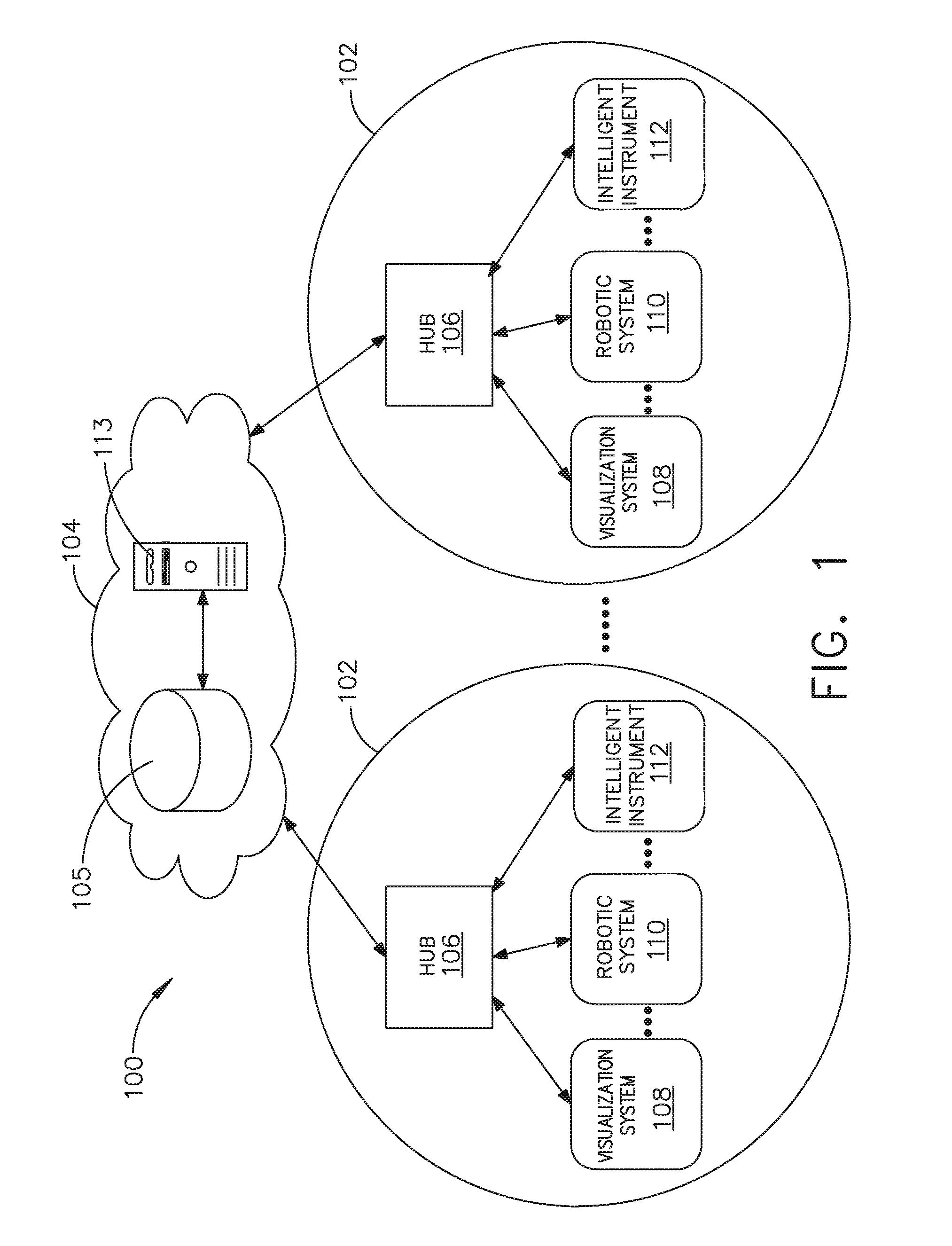
[0197] Referring to FIG. 1, a computer-implemented interactive surgical system 100 includes one or more surgical systems 102 and a cloud-based system (e.g., the cloud 104 that may include a remote server 113 coupled to a storage device 105). Each surgical system 102 includes at least one surgical hub 106 in communication with the cloud 104 that may include a remote server 113. In one example, as illustrated in FIG. 1, the surgical system 102 includes a visualization system 108, a robotic system 110, and a handheld intelligent surgical instrument 112, which are configured to communicate with one another and/or the hub 106. In some aspects, a surgical system 102 may include an M number of hubs 106, an N number of visualization systems 108, an O number of robotic systems 110, and a P number of handheld intelligent surgical instruments 112, where M, N, O, and P are integers greater than or equal to one.
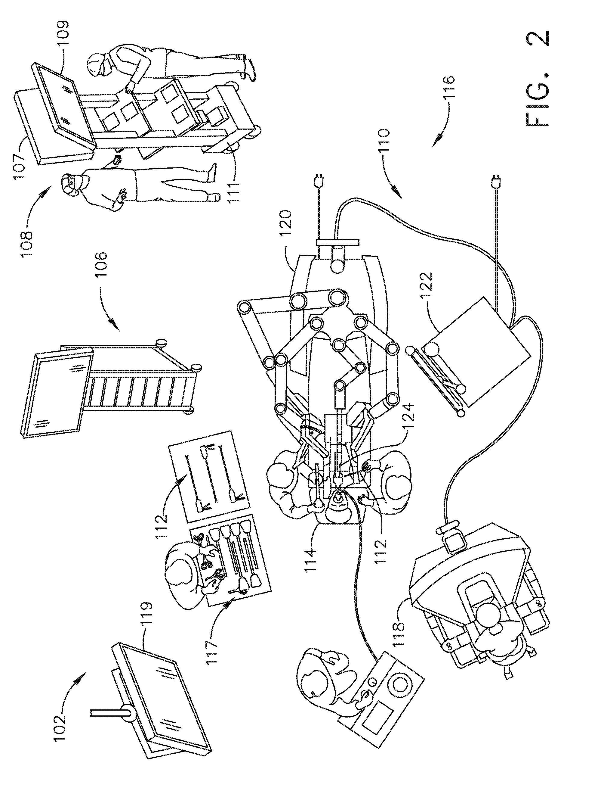
[0198] FIG. 2 depicts an example of a surgical system 102 being used to perform a surgical procedure on a patient who is lying down on an operating table 114 in a surgical operating room 116. A robotic system 110 is used in the surgical procedure as a part of the surgical system 102. The robotic system 110 includes a surgeon's console 118, a patient side cart 120 (surgical robot), and a surgical robotic hub 122. The patient side cart 120 can manipulate at least one removably coupled surgical tool 117 through a minimally invasive incision in the body of the patient while the surgeon views the surgical site through the surgeon's console 118. An image of the surgical site can be obtained by a medical imaging device 124, which can be manipulated by the patient side cart 120 to orient the imaging device 124. The robotic hub 122 can be used to process the images of the surgical site for subsequent display to the surgeon through the surgeon's console 118.
[0199] Other types of robotic systems can be readily adapted for use with the surgical system 102. Various examples of robotic systems and surgical tools that are suitable for use with the present disclosure are described in U.S. Provisional Patent Application Ser. No. 62/611,339, titled ROBOT ASSISTED SURGICAL PLATFORM, filed Dec. 28, 2017, the disclosure of which is herein incorporated by reference in its entirety.
[0200] Various examples of cloud-based analytics that are performed by the cloud 104, and are suitable for use with the present disclosure, are described in U.S. Provisional Patent Application Ser. No. 62/611,340, titled CLOUD-BASED MEDICAL ANALYTICS, filed Dec. 28, 2017, the disclosure of which is herein incorporated by reference in its entirety.
[0201] In various aspects, the imaging device 124 includes at least one image sensor and one or more optical components. Suitable image sensors include, but are not limited to, Charge-Coupled Device (CCD) sensors and Complementary Metal-Oxide Semiconductor (CMOS) sensors.
[0202] The optical components of the imaging device 124 may include one or more illumination sources and/or one or more lenses. The one or more illumination sources may be directed to illuminate portions of the surgical field. The one or more image sensors may receive light reflected or refracted from the surgical field, including light reflected or refracted from tissue and/or surgical instruments.
[0203] The one or more illumination sources may be configured to radiate electromagnetic energy in the visible spectrum as well as the invisible spectrum. The visible spectrum, sometimes referred to as the optical spectrum or luminous spectrum, is that portion of the electromagnetic spectrum that is visible to (i.e., can be detected by) the human eye and may be referred to as visible light or simply light. A typical human eye will respond to wavelengths in air that are from about 380 nm to about 750 nm.
[0204] The invisible spectrum (i.e., the non-luminous spectrum) is that portion of the electromagnetic spectrum that lies below and above the visible spectrum (i.e., wavelengths below about 380 nm and above about 750 nm). The invisible spectrum is not detectable by the human eye. Wavelengths greater than about 750 nm are longer than the red visible spectrum, and they become invisible infrared (IR), microwave, and radio electromagnetic radiation. Wavelengths less than about 380 nm are shorter than the violet spectrum, and they become invisible ultraviolet, x-ray, and gamma ray electromagnetic radiation.
[0205] In various aspects, the imaging device 124 is configured for use in a minimally invasive procedure. Examples of imaging devices suitable for use with the present disclosure include, but not limited to, an arthroscope, angioscope, bronchoscope, choledochoscope, colonoscope, cytoscope, duodenoscope, enteroscope, esophagogastro-duodenoscope (gastroscope), endoscope, laryngoscope, nasopharyngo-neproscope, sigmoidoscope, thoracoscope, and ureteroscope.
[0206] In one aspect, the imaging device employs multi-spectrum monitoring to discriminate topography and underlying structures. A multi-spectral image is one that captures image data within specific wavelength ranges across the electromagnetic spectrum. The wavelengths may be separated by filters or by the use of instruments that are sensitive to particular wavelengths, including light from frequencies beyond the visible light range, e.g., IR and ultraviolet. Spectral imaging can allow extraction of additional information the human eye fails to capture with its receptors for red, green, and blue. The use of multi-spectral imaging is described in greater detail under the heading "Advanced Imaging Acquisition Module" in U.S. Provisional Patent Application Ser. No. 62/611,341, titled INTERACTIVE SURGICAL PLATFORM, filed Dec. 28, 2017, the disclosure of which is herein incorporated by reference in its entirety. Multi-spectrum monitoring can be a useful tool in relocating a surgical field after a surgical task is completed to perform one or more of the previously described tests on the treated tissue.
[0207] It is axiomatic that strict sterilization of the operating room and surgical equipment is required during any surgery. The strict hygiene and sterilization conditions required in a "surgical theater," i.e., an operating or treatment room, necessitate the highest possible sterility of all medical devices and equipment. Part of that sterilization process is the need to sterilize anything that comes in contact with the patient or penetrates the sterile field, including the imaging device 124 and its attachments and components. It will be appreciated that the sterile field may be considered a specified area, such as within a tray or on a sterile towel, that is considered free of microorganisms, or the sterile field may be considered an area, immediately around a patient, who has been prepared for a surgical procedure. The sterile field may include the scrubbed team members, who are properly attired, and all furniture and fixtures in the area.
[0208] In various aspects, the visualization system 108 includes one or more imaging sensors, one or more image-processing units, one or more storage arrays, and one or more displays that are strategically arranged with respect to the sterile field, as illustrated in FIG. 2. In one aspect, the visualization system 108 includes an interface for HL7, PACS, and EMR. Various components of the visualization system 108 are described under the heading "Advanced Imaging Acquisition Module" in U.S. Provisional Patent Application Ser. No. 62/611,341, titled INTERACTIVE SURGICAL PLATFORM, filed Dec. 28, 2017, the disclosure of which is herein incorporated by reference in its entirety.
[0209] As illustrated in FIG. 2, a primary display 119 is positioned in the sterile field to be visible to an operator at the operating table 114. In addition, a visualization tower 111 is positioned outside the sterile field. The visualization tower 111 includes a first non-sterile display 107 and a second non-sterile display 109, which face away from each other. The visualization system 108, guided by the hub 106, is configured to utilize the displays 107, 109, and 119 to coordinate information flow to operators inside and outside the sterile field. For example, the hub 106 may cause the visualization system 108 to display a snapshot of a surgical site, as recorded by an imaging device 124, on a non-sterile display 107 or 109, while maintaining a live feed of the surgical site on the primary display 119. The snapshot on the non-sterile display 107 or 109 can permit a non-sterile operator to perform a diagnostic step relevant to the surgical procedure, for example.
[0210] In one aspect, the hub 106 is also configured to route a diagnostic input or feedback entered by a non-sterile operator at the visualization tower 111 to the primary display 119 within the sterile field, where it can be viewed by a sterile operator at the operating table. In one example, the input can be in the form of a modification to the snapshot displayed on the non-sterile display 107 or 109, which can be routed to the primary display 119 by the hub 106.
[0211] Referring to FIG. 2, a surgical instrument 112 is being used in the surgical procedure as part of the surgical system 102. The hub 106 is also configured to coordinate information flow to a display of the surgical instrument 112. For example, coordinate information flow is further described in U.S. Provisional Patent Application Ser. No. 62/611,341, titled INTERACTIVE SURGICAL PLATFORM, filed Dec. 28, 2017, the disclosure of which is herein incorporated by reference in its entirety. A diagnostic input or feedback entered by a non-sterile operator at the visualization tower 111 can be routed by the hub 106 to the surgical instrument display 115 within the sterile field, where it can be viewed by the operator of the surgical instrument 112. Example surgical instruments that are suitable for use with the surgical system 102 are described under the heading "Surgical Instrument Hardware" in U.S. Provisional Patent Application Ser. No. 62/611,341, titled INTERACTIVE SURGICAL PLATFORM, filed Dec. 28, 2017, the disclosure of which is herein incorporated by reference in its entirety, for example.
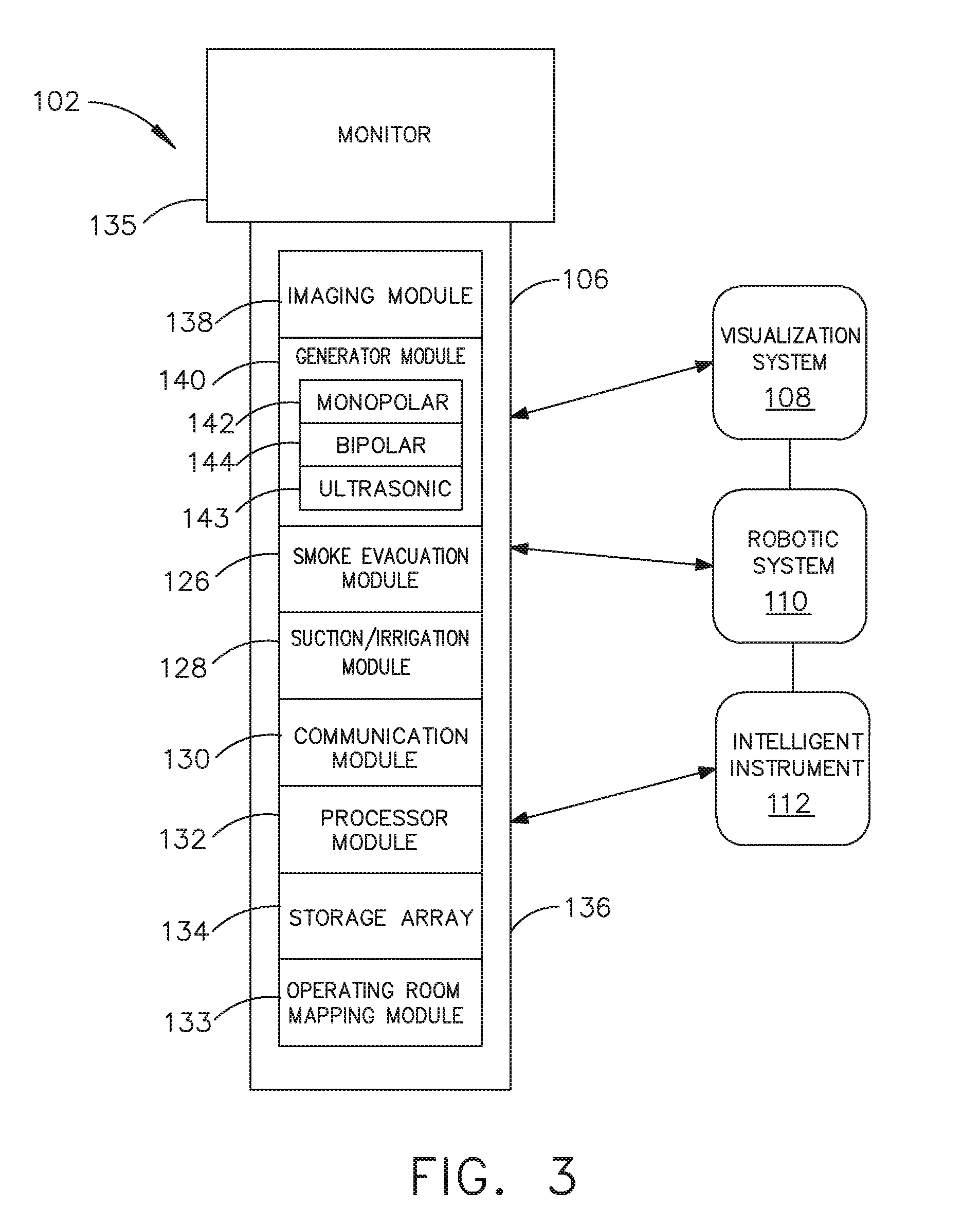
[0212] Referring now to FIG. 3, a hub 106 is depicted in communication with a visualization system 108, a robotic system 110, and a handheld intelligent surgical instrument 112. The hub 106 includes a hub display 135, an imaging module 138, a generator module 140 (which can include a monopolar generator 142, a bipolar generator 144, and/or an ultrasonic generator 143), a communication module 130, a processor module 132, and a storage array 134. In certain aspects, as illustrated in FIG. 3, the hub 106 further includes a smoke evacuation module 126, a suction/irrigation module 128, and/or an OR mapping module 133.
[0213] During a surgical procedure, energy application to tissue, for sealing and/or cutting, is generally associated with smoke evacuation, suction of excess fluid, and/or irrigation of the tissue. Fluid, power, and/or data lines from different sources are often entangled during the surgical procedure. Valuable time can be lost addressing this issue during a surgical procedure. Detangling the lines may necessitate disconnecting the lines from their respective modules, which may require resetting the modules. The hub modular enclosure 136 offers a unified environment for managing the power, data, and fluid lines, which reduces the frequency of entanglement between such lines.
[0214] Aspects of the present disclosure present a surgical hub for use in a surgical procedure that involves energy application to tissue at a surgical site. The surgical hub includes a hub enclosure and a combo generator module slidably receivable in a docking station of the hub enclosure. The docking station includes data and power contacts. The combo generator module includes two or more of an ultrasonic energy generator component, a bipolar RF energy generator component, and a monopolar RF energy generator component that are housed in a single unit. In one aspect, the combo generator module also includes a smoke evacuation component, at least one energy delivery cable for connecting the combo generator module to a surgical instrument, at least one smoke evacuation component configured to evacuate smoke, fluid, and/or particulates generated by the application of therapeutic energy to the tissue, and a fluid line extending from the remote surgical site to the smoke evacuation component.
[0215] In one aspect, the fluid line is a first fluid line and a second fluid line extends from the remote surgical site to a suction and irrigation module slidably received in the hub enclosure. In one aspect, the hub enclosure comprises a fluid interface.
[0216] Certain surgical procedures may require the application of more than one energy type to the tissue. One energy type may be more beneficial for cutting the tissue, while another different energy type may be more beneficial for sealing the tissue. For example, a bipolar generator can be used to seal the tissue while an ultrasonic generator can be used to cut the sealed tissue. Aspects of the present disclosure present a solution where a hub modular enclosure 136 is configured to accommodate different generators, and facilitate an interactive communication therebetween. One of the advantages of the hub modular enclosure 136 is enabling the quick removal and/or replacement of various modules.
[0217] Aspects of the present disclosure present a modular surgical enclosure for use in a surgical procedure that involves energy application to tissue. The modular surgical enclosure includes a first energy-generator module, configured to generate a first energy for application to the tissue, and a first docking station comprising a first docking port that includes first data and power contacts, wherein the first energy-generator module is slidably movable into an electrical engagement with the power and data contacts and wherein the first energy-generator module is slidably movable out of the electrical engagement with the first power and data contacts,
[0218] Further to the above, the modular surgical enclosure also includes a second energy-generator module configured to generate a second energy, different than the first energy, for application to the tissue, and a second docking station comprising a second docking port that includes second data and power contacts, wherein the second energy-generator module is slidably movable into an electrical engagement with the power and data contacts, and wherein the second energy-generator module is slidably movable out of the electrical engagement with the second power and data contacts.
[0219] In addition, the modular surgical enclosure also includes a communication bus between the first docking port and the second docking port, configured to facilitate communication between the first energy-generator module and the second energy-generator module.
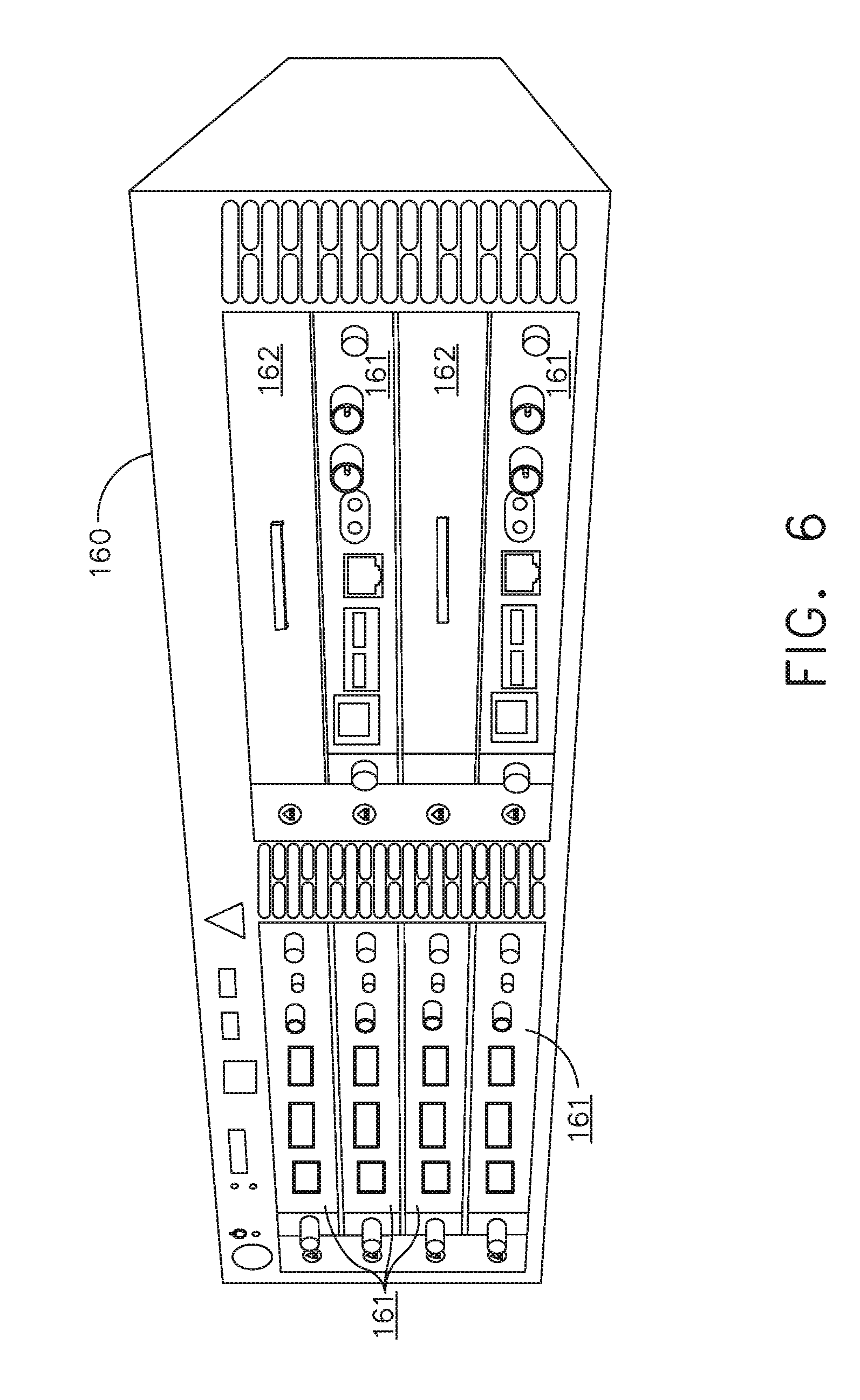
[0220] Referring to FIGS. 3-7, aspects of the present disclosure are presented for a hub modular enclosure 136 that allows the modular integration of a generator module 140, a smoke evacuation module 126, and a suction/irrigation module 128. The hub modular enclosure 136 further facilitates interactive communication between the modules 140, 126, 128. As illustrated in FIG. 5, the generator module 140 can be a generator module with integrated monopolar, bipolar, and ultrasonic components supported in a single housing unit 139 slidably insertable into the hub modular enclosure 136. As illustrated in FIG. 5, the generator module 140 can be configured to connect to a monopolar device 146, a bipolar device 147, and an ultrasonic device 148. Alternatively, the generator module 140 may comprise a series of monopolar, bipolar, and/or ultrasonic generator modules that interact through the hub modular enclosure 136. The hub modular enclosure 136 can be configured to facilitate the insertion of multiple generators and interactive communication between the generators docked into the hub modular enclosure 136 so that the generators would act as a single generator.
[0221] In one aspect, the hub modular enclosure 136 comprises a modular power and communication backplane 149 with external and wireless communication headers to enable the removable attachment of the modules 140, 126, 128 and interactive communication therebetween.
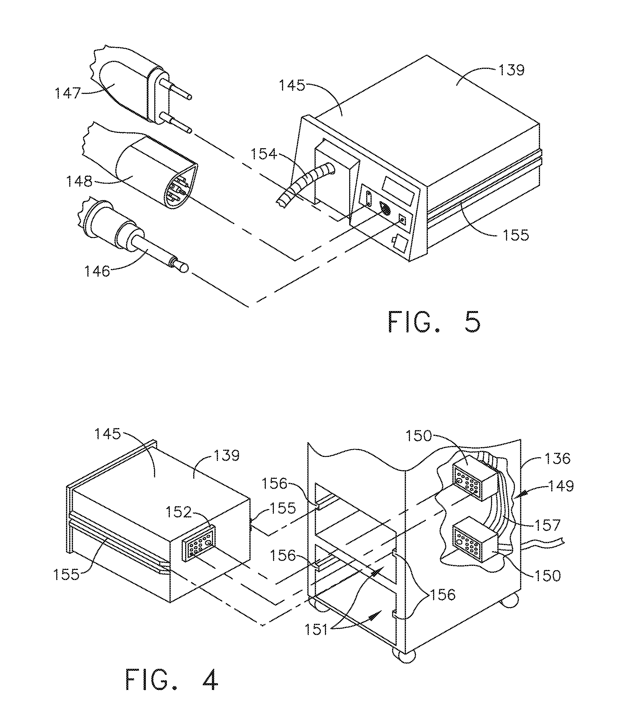
[0222] In one aspect, the hub modular enclosure 136 includes docking stations, or drawers, 151, herein also referred to as drawers, which are configured to slidably receive the modules 140, 126, 128. FIG. 4 illustrates a partial perspective view of a surgical hub enclosure 136, and a combo generator module 145 slidably receivable in a docking station 151 of the surgical hub enclosure 136. A docking port 152 with power and data contacts on a rear side of the combo generator module 145 is configured to engage a corresponding docking port 150 with power and data contacts of a corresponding docking station 151 of the hub modular enclosure 136 as the combo generator module 145 is slid into position within the corresponding docking station 151 of the hub module enclosure 136. In one aspect, the combo generator module 145 includes a bipolar, ultrasonic, and monopolar module and a smoke evacuation module integrated together into a single housing unit 139, as illustrated in FIG. 5.
[0223] In various aspects, the smoke evacuation module 126 includes a fluid line 154 that conveys captured/collected smoke and/or fluid away from a surgical site and to, for example, the smoke evacuation module 126. Vacuum suction originating from the smoke evacuation module 126 can draw the smoke into an opening of a utility conduit at the surgical site. The utility conduit, coupled to the fluid line, can be in the form of a flexible tube terminating at the smoke evacuation module 126. The utility conduit and the fluid line define a fluid path extending toward the smoke evacuation module 126 that is received in the hub enclosure 136.
[0224] In various aspects, the suction/irrigation module 128 is coupled to a surgical tool comprising an aspiration fluid line and a suction fluid line. In one example, the aspiration and suction fluid lines are in the form of flexible tubes extending from the surgical site toward the suction/irrigation module 128. One or more drive systems can be configured to cause irrigation and aspiration of fluids to and from the surgical site.
[0225] In one aspect, the surgical tool includes a shaft having an end effector at a distal end thereof and at least one energy treatment associated with the end effector, an aspiration tube, and an irrigation tube. The aspiration tube can have an inlet port at a distal end thereof and the aspiration tube extends through the shaft. Similarly, an irrigation tube can extend through the shaft and can have an inlet port in proximity to the energy deliver implement. The energy deliver implement is configured to deliver ultrasonic and/or RF energy to the surgical site and is coupled to the generator module 140 by a cable extending initially through the shaft.
[0226] The irrigation tube can be in fluid communication with a fluid source, and the aspiration tube can be in fluid communication with a vacuum source. The fluid source and/or the vacuum source can be housed in the suction/irrigation module 128. In one example, the fluid source and/or the vacuum source can be housed in the hub enclosure 136 separately from the suction/irrigation module 128. In such example, a fluid interface can be configured to connect the suction/irrigation module 128 to the fluid source and/or the vacuum source.
[0227] In one aspect, the modules 140, 126, 128 and/or their corresponding docking stations on the hub modular enclosure 136 may include alignment features that are configured to align the docking ports of the modules into engagement with their counterparts in the docking stations of the hub modular enclosure 136. For example, as illustrated in FIG. 4, the combo generator module 145 includes side brackets 155 that are configured to slidably engage with corresponding brackets 156 of the corresponding docking station 151 of the hub modular enclosure 136. The brackets cooperate to guide the docking port contacts of the combo generator module 145 into an electrical engagement with the docking port contacts of the hub modular enclosure 136.
[0228] In some aspects, the drawers 151 of the hub modular enclosure 136 are the same, or substantially the same size, and the modules are adjusted in size to be received in the drawers 151. For example, the side brackets 155 and/or 156 can be larger or smaller depending on the size of the module. In other aspects, the drawers 151 are different in size and are each designed to accommodate a particular module.
[0229] Furthermore, the contacts of a particular module can be keyed for engagement with the contacts of a particular drawer to avoid inserting a module into a drawer with mismatching contacts.
[0230] As illustrated in FIG. 4, the docking port 150 of one drawer 151 can be coupled to the docking port 150 of another drawer 151 through a communications link 157 to facilitate an interactive communication between the modules housed in the hub modular enclosure 136. The docking ports 150 of the hub modular enclosure 136 may alternatively, or additionally, facilitate a wireless interactive communication between the modules housed in the hub modular enclosure 136. Any suitable wireless communication can be employed, such as for example Air Titan-Bluetooth.
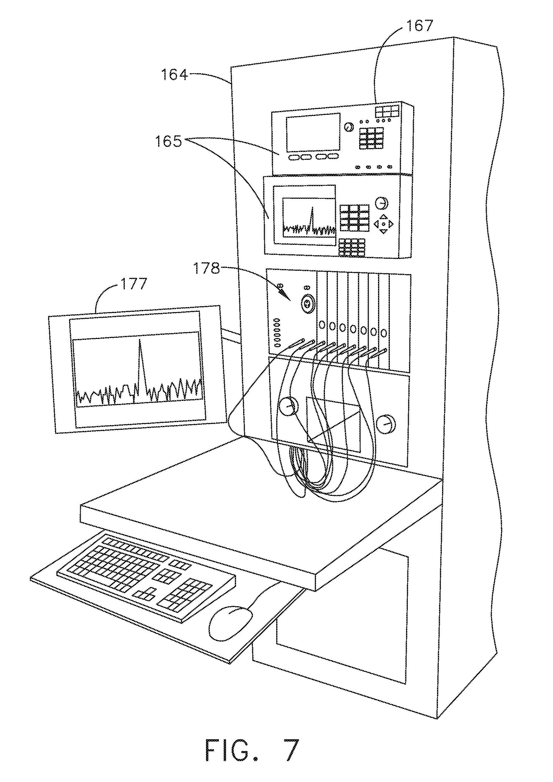
[0231] FIG. 6 illustrates individual power bus attachments for a plurality of lateral docking ports of a lateral modular housing 160 configured to receive a plurality of modules of a surgical hub 206. The lateral modular housing 160 is configured to laterally receive and interconnect the modules 161. The modules 161 are slidably inserted into docking stations 162 of lateral modular housing 160, which includes a backplane for interconnecting the modules 161. As illustrated in FIG. 6, the modules 161 are arranged laterally in the lateral modular housing 160. Alternatively, the modules 161 may be arranged vertically in a lateral modular housing.
[0232] FIG. 7 illustrates a vertical modular housing 164 configured to receive a plurality of modules 165 of the surgical hub 106. The modules 165 are slidably inserted into docking stations, or drawers, 167 of vertical modular housing 164, which includes a backplane for interconnecting the modules 165. Although the drawers 167 of the vertical modular housing 164 are arranged vertically, in certain instances, a vertical modular housing 164 may include drawers that are arranged laterally. Furthermore, the modules 165 may interact with one another through the docking ports of the vertical modular housing 164. In the example of FIG. 7, a display 177 is provided for displaying data relevant to the operation of the modules 165. In addition, the vertical modular housing 164 includes a master module 178 housing a plurality of sub-modules that are slidably received in the master module 178.
[0233] In various aspects, the imaging module 138 comprises an integrated video processor and a modular light source and is adapted for use with various imaging devices. In one aspect, the imaging device is comprised of a modular housing that can be assembled with a light source module and a camera module. The housing can be a disposable housing. In at least one example, the disposable housing is removably coupled to a reusable controller, a light source module, and a camera module. The light source module and/or the camera module can be selectively chosen depending on the type of surgical procedure. In one aspect, the camera module comprises a CCD sensor. In another aspect, the camera module comprises a CMOS sensor. In another aspect, the camera module is configured for scanned beam imaging. Likewise, the light source module can be configured to deliver a white light or a different light, depending on the surgical procedure.
[0234] During a surgical procedure, removing a surgical device from the surgical field and replacing it with another surgical device that includes a different camera or a different light source can be inefficient. Temporarily losing sight of the surgical field may lead to undesirable consequences. The module imaging device of the present disclosure is configured to permit the replacement of a light source module or a camera module midstream during a surgical procedure, without having to remove the imaging device from the surgical field.
[0235] In one aspect, the imaging device comprises a tubular housing that includes a plurality of channels. A first channel is configured to slidably receive the camera module, which can be configured for a snap-fit engagement with the first channel. A second channel is configured to slidably receive the light source module, which can be configured for a snap-fit engagement with the second channel. In another example, the camera module and/or the light source module can be rotated into a final position within their respective channels. A threaded engagement can be employed in lieu of the snap-fit engagement.
[0236] In various examples, multiple imaging devices are placed at different positions in the surgical field to provide multiple views. The imaging module 138 can be configured to switch between the imaging devices to provide an optimal view. In various aspects, the imaging module 138 can be configured to integrate the images from the different imaging device.
[0237] Various image processors and imaging devices suitable for use with the present disclosure are described in U.S. Pat. No. 7,995,045, titled COMBINED SBI AND CONVENTIONAL IMAGE PROCESSOR, which issued on Aug. 9, 2011, which is herein incorporated by reference in its entirety. In addition, U.S. Pat. No. 7,982,776, titled SBI MOTION ARTIFACT REMOVAL APPARATUS AND METHOD, which issued on Jul. 19, 2011, which is herein incorporated by reference in its entirety, describes various systems for removing motion artifacts from image data. Such systems can be integrated with the imaging module 138. Furthermore, U.S. Patent Application Publication No. 2011/0306840, titled CONTROLLABLE MAGNETIC SOURCE TO FIXTURE INTRACORPOREAL APPARATUS, which published on Dec. 15, 2011, and U.S. Patent Application Publication No. 2014/0243597, titled SYSTEM FOR PERFORMING A MINIMALLY INVASIVE SURGICAL PROCEDURE, which published on Aug. 28, 2014, each of which is herein incorporated by reference in its entirety.
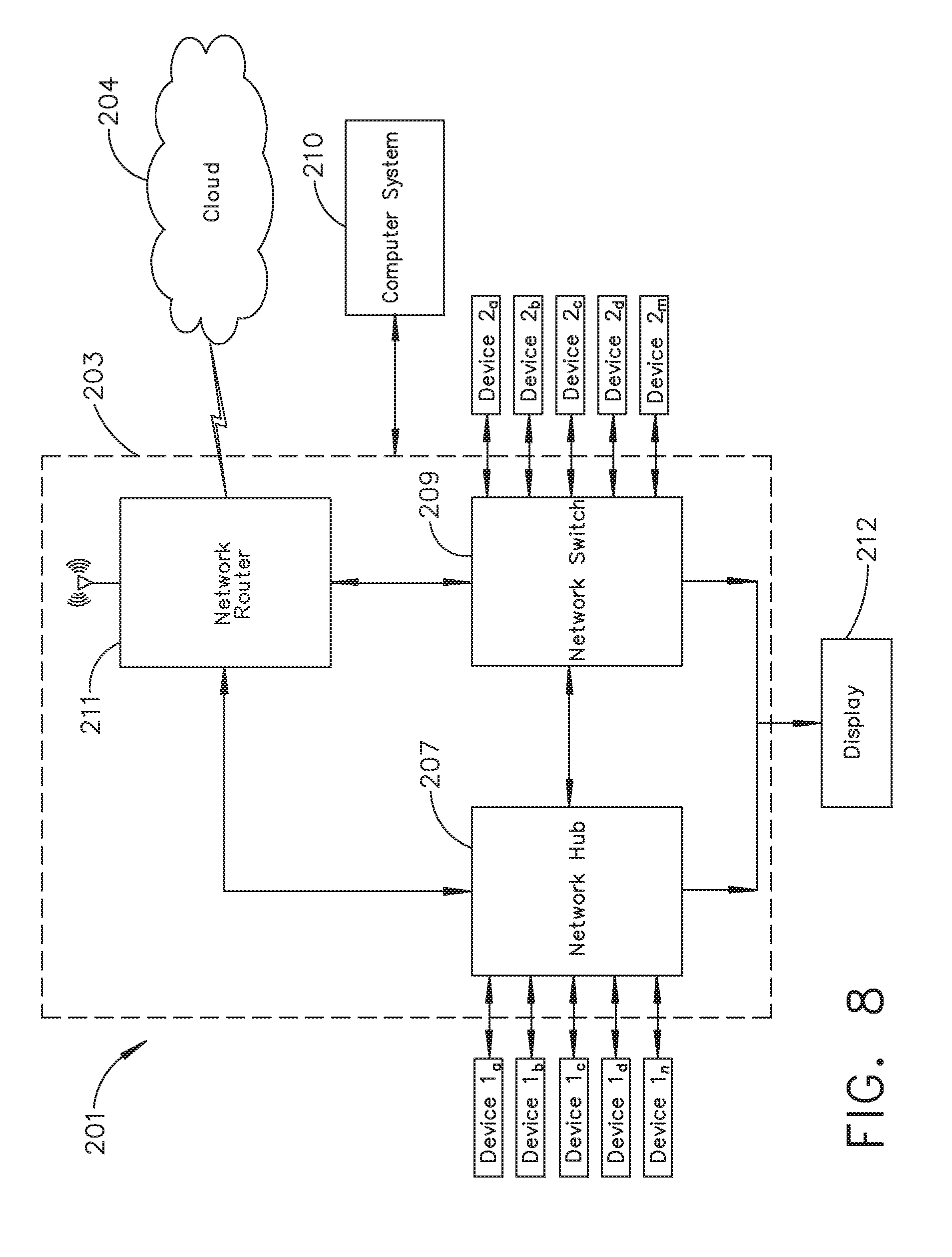
[0238] FIG. 8 illustrates a surgical data network 201 comprising a modular communication hub 203 configured to connect modular devices located in one or more operating theaters of a healthcare facility, or any room in a healthcare facility specially equipped for surgical operations, to a cloud-based system (e.g., the cloud 204 that may include a remote server 213 coupled to a storage device 205). In one aspect, the modular communication hub 203 comprises a network hub 207 and/or a network switch 209 in communication with a network router. The modular communication hub 203 also can be coupled to a local computer system 210 to provide local computer processing and data manipulation. The surgical data network 201 may be configured as passive, intelligent, or switching. A passive surgical data network serves as a conduit for the data, enabling it to go from one device (or segment) to another and to the cloud computing resources. An intelligent surgical data network includes additional features to enable the traffic passing through the surgical data network to be monitored and to configure each port in the network hub 207 or network switch 209. An intelligent surgical data network may be referred to as a manageable hub or switch. A switching hub reads the destination address of each packet and then forwards the packet to the correct port.
[0239] Modular devices 1a-1n located in the operating theater may be coupled to the modular communication hub 203. The network hub 207 and/or the network switch 209 may be coupled to a network router 211 to connect the devices 1a-1n to the cloud 204 or the local computer system 210. Data associated with the devices 1a-1n may be transferred to cloud-based computers via the router for remote data processing and manipulation. Data associated with the devices 1a-1n may also be transferred to the local computer system 210 for local data processing and manipulation. Modular devices 2a-2m located in the same operating theater also may be coupled to a network switch 209. The network switch 209 may be coupled to the network hub 207 and/or the network router 211 to connect to the devices 2a-2m to the cloud 204. Data associated with the devices 2a-2n may be transferred to the cloud 204 via the network router 211 for data processing and manipulation. Data associated with the devices 2a-2m may also be transferred to the local computer system 210 for local data processing and manipulation.
[0240] It will be appreciated that the surgical data network 201 may be expanded by interconnecting multiple network hubs 207 and/or multiple network switches 209 with multiple network routers 211. The modular communication hub 203 may be contained in a modular control tower configured to receive multiple devices 1a-1n/2a-2m. The local computer system 210 also may be contained in a modular control tower. The modular communication hub 203 is connected to a display 212 to display images obtained by some of the devices 1a-1n/2a-2m, for example during surgical procedures. In various aspects, the devices 1a-1n/2a-2m may include, for example, various modules such as an imaging module 138 coupled to an endoscope, a generator module 140 coupled to an energy-based surgical device, a smoke evacuation module 126, a suction/irrigation module 128, a communication module 130, a processor module 132, a storage array 134, a surgical device coupled to a display, and/or a non-contact sensor module, among other modular devices that may be connected to the modular communication hub 203 of the surgical data network 201.
[0241] In one aspect, the surgical data network 201 may comprise a combination of network hub(s), network switch(es), and network router(s) connecting the devices 1a-1n/2a-2m to the cloud. Any one of or all of the devices 1a-1n/2a-2m coupled to the network hub or network switch may collect data in real time and transfer the data to cloud computers for data processing and manipulation. It will be appreciated that cloud computing relies on sharing computing resources rather than having local servers or personal devices to handle software applications. The word "cloud" may be used as a metaphor for "the Internet," although the term is not limited as such. Accordingly, the term "cloud computing" may be used herein to refer to "a type of Internet-based computing," where different services--such as servers, storage, and applications--are delivered to the modular communication hub 203 and/or computer system 210 located in the surgical theater (e.g., a fixed, mobile, temporary, or field operating room or space) and to devices connected to the modular communication hub 203 and/or computer system 210 through the Internet. The cloud infrastructure may be maintained by a cloud service provider. In this context, the cloud service provider may be the entity that coordinates the usage and control of the devices 1a-1n/2a-2m located in one or more operating theaters. The cloud computing services can perform a large number of calculations based on the data gathered by smart surgical instruments, robots, and other computerized devices located in the operating theater. The hub hardware enables multiple devices or connections to be connected to a computer that communicates with the cloud computing resources and storage.
[0242] Applying cloud computer data processing techniques on the data collected by the devices 1a-1n/2a-2m, the surgical data network provides improved surgical outcomes, reduced costs, and improved patient satisfaction. At least some of the devices 1a-1n/2a-2m may be employed to view tissue states to assess leaks or perfusion of sealed tissue after a tissue sealing and cutting procedure. At least some of the devices 1a-1n/2a-2m may be employed to identify pathology, such as the effects of diseases, using the cloud-based computing to examine data including images of samples of body tissue for diagnostic purposes. This includes localization and margin confirmation of tissue and phenotypes. At least some of the devices 1a-1n/2a-2m may be employed to identify anatomical structures of the body using a variety of sensors integrated with imaging devices and techniques such as overlaying images captured by multiple imaging devices. The data gathered by the devices 1a-1n/2a-2m, including image data, may be transferred to the cloud 204 or the local computer system 210 or both for data processing and manipulation including image processing and manipulation. The data may be analyzed to improve surgical procedure outcomes by determining if further treatment, such as the application of endoscopic intervention, emerging technologies, a targeted radiation, targeted intervention, and precise robotics to tissue-specific sites and conditions, may be pursued. Such data analysis may further employ outcome analytics processing, and using standardized approaches may provide beneficial feedback to either confirm surgical treatments and the behavior of the surgeon or suggest modifications to surgical treatments and the behavior of the surgeon.
[0243] In one implementation, the operating theater devices 1a-1n may be connected to the modular communication hub 203 over a wired channel or a wireless channel depending on the configuration of the devices 1a-1n to a network hub. The network hub 207 may be implemented, in one aspect, as a local network broadcast device that works on the physical layer of the Open System Interconnection (OSI) model. The network hub provides connectivity to the devices 1a-1n located in the same operating theater network. The network hub 207 collects data in the form of packets and sends them to the router in half duplex mode. The network hub 207 does not store any media access control/Internet Protocol (MAC/IP) to transfer the device data. Only one of the devices 1a-1n can send data at a time through the network hub 207. The network hub 207 has no routing tables or intelligence regarding where to send information and broadcasts all network data across each connection and to a remote server 213 (FIG. 9) over the cloud 204. The network hub 207 can detect basic network errors such as collisions, but having all information broadcast to multiple ports can be a security risk and cause bottlenecks.
[0244] In another implementation, the operating theater devices 2a-2m may be connected to a network switch 209 over a wired channel or a wireless channel. The network switch 209 works in the data link layer of the OSI model. The network switch 209 is a multicast device for connecting the devices 2a-2m located in the same operating theater to the network. The network switch 209 sends data in the form of frames to the network router 211 and works in full duplex mode. Multiple devices 2a-2m can send data at the same time through the network switch 209. The network switch 209 stores and uses MAC addresses of the devices 2a-2m to transfer data.
[0245] The network hub 207 and/or the network switch 209 are coupled to the network router 211 for connection to the cloud 204. The network router 211 works in the network layer of the OSI model. The network router 211 creates a route for transmitting data packets received from the network hub 207 and/or network switch 211 to cloud-based computer resources for further processing and manipulation of the data collected by any one of or all the devices 1a-1n/2a-2m. The network router 211 may be employed to connect two or more different networks located in different locations, such as, for example, different operating theaters of the same healthcare facility or different networks located in different operating theaters of different healthcare facilities. The network router 211 sends data in the form of packets to the cloud 204 and works in full duplex mode. Multiple devices can send data at the same time. The network router 211 uses IP addresses to transfer data.
[0246] In one example, the network hub 207 may be implemented as a USB hub, which allows multiple USB devices to be connected to a host computer. The USB hub may expand a single USB port into several tiers so that there are more ports available to connect devices to the host system computer. The network hub 207 may include wired or wireless capabilities to receive information over a wired channel or a wireless channel. In one aspect, a wireless USB short-range, high-bandwidth wireless radio communication protocol may be employed for communication between the devices 1a-1n and devices 2a-2m located in the operating theater.
[0247] In other examples, the operating theater devices 1a-1n/2a-2m may communicate to the modular communication hub 203 via Bluetooth wireless technology standard for exchanging data over short distances (using short-wavelength UHF radio waves in the ISM band from 2.4 to 2.485 GHz) from fixed and mobile devices and building personal area networks (PANs). In other aspects, the operating theater devices 1a-1n/2a-2m may communicate to the modular communication hub 203 via a number of wireless or wired communication standards or protocols, including but not limited to Wi-Fi (IEEE 802.11 family), WiMAX (IEEE 802.16 family), IEEE 802.20, long-term evolution (LTE), and Ev-DO, HSPA+, HSDPA+, HSUPA+, EDGE, GSM, GPRS, CDMA, TDMA, DECT, and Ethernet derivatives thereof, as well as any other wireless and wired protocols that are designated as 3G, 4G, 5G, and beyond. The computing module may include a plurality of communication modules. For instance, a first communication module may be dedicated to shorter-range wireless communications such as Wi-Fi and Bluetooth, and a second communication module may be dedicated to longer-range wireless communications such as GPS, EDGE, GPRS, CDMA, WiMAX, LTE, Ev-DO, and others.
[0248] The modular communication hub 203 may serve as a central connection for one or all of the operating theater devices 1a-1n/2a-2m and handles a data type known as frames. Frames carry the data generated by the devices 1a-1n/2a-2m. When a frame is received by the modular communication hub 203, it is amplified and transmitted to the network router 211, which transfers the data to the cloud computing resources by using a number of wireless or wired communication standards or protocols, as described herein.
[0249] The modular communication hub 203 can be used as a standalone device or be connected to compatible network hubs and network switches to form a larger network. The modular communication hub 203 is generally easy to install, configure, and maintain, making it a good option for networking the operating theater devices 1a-1n/2a-2m.
[0250] FIG. 9 illustrates a computer-implemented interactive surgical system 200. The computer-implemented interactive surgical system 200 is similar in many respects to the computer-implemented interactive surgical system 100. For example, the computer-implemented interactive surgical system 200 includes one or more surgical systems 202, which are similar in many respects to the surgical systems 102. Each surgical system 202 includes at least one surgical hub 206 in communication with a cloud 204 that may include a remote server 213. In one aspect, the computer-implemented interactive surgical system 200 comprises a modular control tower 236 connected to multiple operating theater devices such as, for example, intelligent surgical instruments, robots, and other computerized devices located in the operating theater. As shown in FIG. 10, the modular control tower 236 comprises a modular communication hub 203 coupled to a computer system 210. As illustrated in the example of FIG. 9, the modular control tower 236 is coupled to an imaging module 238 that is coupled to an endoscope 239, a generator module 240 that is coupled to an energy device 241, a smoke evacuator module 226, a suction/irrigation module 228, a communication module 230, a processor module 232, a storage array 234, a smart device/instrument 235 optionally coupled to a display 237, and a non-contact sensor module 242. The operating theater devices are coupled to cloud computing resources and data storage via the modular control tower 236. A robot hub 222 also may be connected to the modular control tower 236 and to the cloud computing resources. The devices/instruments 235, visualization systems 208, among others, may be coupled to the modular control tower 236 via wired or wireless communication standards or protocols, as described herein. The modular control tower 236 may be coupled to a hub display 215 (e.g., monitor, screen) to display and overlay images received from the imaging module, device/instrument display, and/or other visualization systems 208. The hub display also may display data received from devices connected to the modular control tower in conjunction with images and overlaid images.
[0251] FIG. 10 illustrates a surgical hub 206 comprising a plurality of modules coupled to the modular control tower 236. The modular control tower 236 comprises a modular communication hub 203, e.g., a network connectivity device, and a computer system 210 to provide local processing, visualization, and imaging, for example. As shown in FIG. 10, the modular communication hub 203 may be connected in a tiered configuration to expand the number of modules (e.g., devices) that may be connected to the modular communication hub 203 and transfer data associated with the modules to the computer system 210, cloud computing resources, or both. As shown in FIG. 10, each of the network hubs/switches in the modular communication hub 203 includes three downstream ports and one upstream port. The upstream network hub/switch is connected to a processor to provide a communication connection to the cloud computing resources and a local display 217. Communication to the cloud 204 may be made either through a wired or a wireless communication channel.
[0252] The surgical hub 206 employs a non-contact sensor module 242 to measure the dimensions of the operating theater and generate a map of the surgical theater using either ultrasonic or laser-type non-contact measurement devices. An ultrasound-based non-contact sensor module scans the operating theater by transmitting a burst of ultrasound and receiving the echo when it bounces off the perimeter walls of an operating theater as described under the heading "Surgical Hub Spatial Awareness Within an Operating Room" in U.S. Provisional Patent Application Ser. No. 62/611,341, titled INTERACTIVE SURGICAL PLATFORM, filed Dec. 28, 2017, which is herein incorporated by reference in its entirety, in which the sensor module is configured to determine the size of the operating theater and to adjust Bluetooth-pairing distance limits. A laser-based non-contact sensor module scans the operating theater by transmitting laser light pulses, receiving laser light pulses that bounce off the perimeter walls of the operating theater, and comparing the phase of the transmitted pulse to the received pulse to determine the size of the operating theater and to adjust Bluetooth pairing distance limits, for example.
[0253] The computer system 210 comprises a processor 244 and a network interface 245. The processor 244 is coupled to a communication module 247, storage 248, memory 249, non-volatile memory 250, and input/output interface 251 via a system bus. The system bus can be any of several types of bus structure(s) including the memory bus or memory controller, a peripheral bus or external bus, and/or a local bus using any variety of available bus architectures including, but not limited to, 9-bit bus, Industrial Standard Architecture (ISA), Micro-Charmel Architecture (MSA), Extended ISA (EISA), Intelligent Drive Electronics (IDE), VESA Local Bus (VLB), Peripheral Component Interconnect (PCI), USB, Advanced Graphics Port (AGP), Personal Computer Memory Card International Association bus (PCMCIA), Small Computer Systems Interface (SCSI), or any other proprietary bus.
[0254] The processor 244 may be any single-core or multicore processor such as those known under the trade name ARM Cortex by Texas Instruments. In one aspect, the processor may be an LM4F230H5QR ARM Cortex-M4F Processor Core, available from Texas Instruments, for example, comprising an on-chip memory of 256 KB single-cycle flash memory, or other non-volatile memory, up to 40 MHz, a prefetch buffer to improve performance above 40 MHz, a 32 KB single-cycle serial random access memory (SRAM), an internal read-only memory (ROM) loaded with StellarisWare.RTM. software, a 2 KB electrically erasable programmable read-only memory (EEPROM), and/or one or more pulse width modulation (PWM) modules, one or more quadrature encoder inputs (QEI) analogs, one or more 12-bit analog-to-digital converters (ADCs) with 12 analog input channels, details of which are available for the product datasheet.
[0255] In one aspect, the processor 244 may comprise a safety controller comprising two controller-based families such as TMS570 and RM4x, known under the trade name Hercules ARM Cortex R4, also by Texas Instruments. The safety controller may be configured specifically for IEC 61508 and ISO 26262 safety critical applications, among others, to provide advanced integrated safety features while delivering scalable performance, connectivity, and memory options.
[0256] The system memory includes volatile memory and non-volatile memory. The basic input/output system (BIOS), containing the basic routines to transfer information between elements within the computer system, such as during start-up, is stored in non-volatile memory. For example, the non-volatile memory can include ROM, programmable ROM (PROM), electrically programmable ROM (EPROM), EEPROM, or flash memory. Volatile memory includes random-access memory (RAM), which acts as external cache memory. Moreover, RAM is available in many forms such as SRAM, dynamic RAM (DRAM), synchronous DRAM (SDRAM), double data rate SDRAM (DDR SDRAM), enhanced SDRAM (ESDRAM), Synchlink DRAM (SLDRAM), and direct Rambus RAM (DRRAM).
[0257] The computer system 210 also includes removable/non-removable, volatile/non-volatile computer storage media, such as for example disk storage. The disk storage includes, but is not limited to, devices like a magnetic disk drive, floppy disk drive, tape drive, Jaz drive, Zip drive, LS-60 drive, flash memory card, or memory stick. In addition, the disk storage can include storage media separately or in combination with other storage media including, but not limited to, an optical disc drive such as a compact disc ROM device (CD-ROM), compact disc recordable drive (CD-R Drive), compact disc rewritable drive (CD-RW Drive), or a digital versatile disc ROM drive (DVD-ROM). To facilitate the connection of the disk storage devices to the system bus, a removable or non-removable interface may be employed.
[0258] It is to be appreciated that the computer system 210 includes software that acts as an intermediary between users and the basic computer resources described in a suitable operating environment. Such software includes an operating system. The operating system, which can be stored on the disk storage, acts to control and allocate resources of the computer system. System applications take advantage of the management of resources by the operating system through program modules and program data stored either in the system memory or on the disk storage. It is to be appreciated that various components described herein can be implemented with various operating systems or combinations of operating systems.
[0259] A user enters commands or information into the computer system 210 through input device(s) coupled to the I/O interface 251. The input devices include, but are not limited to, a pointing device such as a mouse, trackball, stylus, touch pad, keyboard, microphone, joystick, game pad, satellite dish, scanner, TV tuner card, digital camera, digital video camera, web camera, and the like. These and other input devices connect to the processor through the system bus via interface port(s). The interface port(s) include, for example, a serial port, a parallel port, a game port, and a USB. The output device(s) use some of the same types of ports as input device(s). Thus, for example, a USB port may be used to provide input to the computer system and to output information from the computer system to an output device. An output adapter is provided to illustrate that there are some output devices like monitors, displays, speakers, and printers, among other output devices that require special adapters. The output adapters include, by way of illustration and not limitation, video and sound cards that provide a means of connection between the output device and the system bus. It should be noted that other devices and/or systems of devices, such as remote computer(s), provide both input and output capabilities.
[0260] The computer system 210 can operate in a networked environment using logical connections to one or more remote computers, such as cloud computer(s), or local computers. The remote cloud computer(s) can be a personal computer, server, router, network PC, workstation, microprocessor-based appliance, peer device, or other common network node, and the like, and typically includes many or all of the elements described relative to the computer system. For purposes of brevity, only a memory storage device is illustrated with the remote computer(s). The remote computer(s) is logically connected to the computer system through a network interface and then physically connected via a communication connection. The network interface encompasses communication networks such as local area networks (LANs) and wide area networks (WANs). LAN technologies include Fiber Distributed Data Interface (FDDI), Copper Distributed Data Interface (CDDI), Ethernet/IEEE 802.3, Token Ring/IEEE 802.5 and the like. WAN technologies include, but are not limited to, point-to-point links, circuit-switching networks like Integrated Services Digital Networks (ISDN) and variations thereon, packet-switching networks, and Digital Subscriber Lines (DSL).
[0261] In various aspects, the computer system 210 of FIG. 10, the imaging module 238 and/or visualization system 208, and/or the processor module 232 of FIGS. 9-10, may comprise an image processor, image-processing engine, media processor, or any specialized digital signal processor (DSP) used for the processing of digital images. The image processor may employ parallel computing with single instruction, multiple data (SIMD) or multiple instruction, multiple data (MIMD) technologies to increase speed and efficiency. The digital image-processing engine can perform a range of tasks. The image processor may be a system on a chip with multicore processor architecture.
[0262] The communication connection(s) refers to the hardware/software employed to connect the network interface to the bus. While the communication connection is shown for illustrative clarity inside the computer system, it can also be external to the computer system 210. The hardware/software necessary for connection to the network interface includes, for illustrative purposes only, internal and external technologies such as modems, including regular telephone-grade modems, cable modems, and DSL modems, ISDN adapters, and Ethernet cards.
[0263] FIG. 11 illustrates a functional block diagram of one aspect of a USB network hub 300 device, in accordance with at least one aspect of the present disclosure. In the illustrated aspect, the USB network hub device 300 employs a TUSB2036 integrated circuit hub by Texas Instruments. The USB network hub 300 is a CMOS device that provides an upstream USB transceiver port 302 and up to three downstream USB transceiver ports 304, 306, 308 in compliance with the USB 2.0 specification. The upstream USB transceiver port 302 is a differential root data port comprising a differential data minus (DM0) input paired with a differential data plus (DP0) input. The three downstream USB transceiver ports 304, 306, 308 are differential data ports where each port includes differential data plus (DP1-DP3) outputs paired with differential data minus (DM1-DM3) outputs.
[0264] The USB network hub 300 device is implemented with a digital state machine instead of a microcontroller, and no firmware programming is required. Fully compliant USB transceivers are integrated into the circuit for the upstream USB transceiver port 302 and all downstream USB transceiver ports 304, 306, 308. The downstream USB transceiver ports 304, 306, 308 support both full-speed and low-speed devices by automatically setting the slew rate according to the speed of the device attached to the ports. The USB network hub 300 device may be configured either in bus-powered or self-powered mode and includes a hub power logic 312 to manage power.
[0265] The USB network hub 300 device includes a serial interface engine 310 (SIE). The SIE 310 is the front end of the USB network hub 300 hardware and handles most of the protocol described in chapter 8 of the USB specification. The SIE 310 typically comprehends signaling up to the transaction level. The functions that it handles could include: packet recognition, transaction sequencing, SOP, EOP, RESET, and RESUME signal detection/generation, clock/data separation, non-return-to-zero invert (NRZI) data encoding/decoding and bit-stuffing, CRC generation and checking (token and data), packet ID (PID) generation and checking/decoding, and/or serial-parallel/parallel-serial conversion. The 310 receives a clock input 314 and is coupled to a suspend/resume logic and frame timer 316 circuit and a hub repeater circuit 318 to control communication between the upstream USB transceiver port 302 and the downstream USB transceiver ports 304, 306, 308 through port logic circuits 320, 322, 324. The SIE 310 is coupled to a command decoder 326 via interface logic 328 to control commands from a serial EEPROM via a serial EEPROM interface 330.
[0266] In various aspects, the USB network hub 300 can connect 127 functions configured in up to six logical layers (tiers) to a single computer. Further, the USB network hub 300 can connect to all peripherals using a standardized four-wire cable that provides both communication and power distribution. The power configurations are bus-powered and self-powered modes. The USB network hub 300 may be configured to support four modes of power management: a bus-powered hub, with either individual-port power management or ganged-port power management, and the self-powered hub, with either individual-port power management or ganged-port power management. In one aspect, using a USB cable, the USB network hub 300, the upstream USB transceiver port 302 is plugged into a USB host controller, and the downstream USB transceiver ports 304, 306, 308 are exposed for connecting USB compatible devices, and so forth.
[0267] Additional details regarding the structure and function of the surgical hub and/or surgical hub networks can be found in U.S. Provisional Patent Application No. 62/659,900, titled METHOD OF HUB COMMUNICATION, filed Apr. 19, 2018, which is hereby incorporated by reference herein in its entirety.
Cloud System Hardware and Functional Modules
[0268] FIG. 12 is a block diagram of the computer-implemented interactive surgical system, in accordance with at least one aspect of the present disclosure. In one aspect, the computer-implemented interactive surgical system is configured to monitor and analyze data related to the operation of various surgical systems that include surgical hubs, surgical instruments, robotic devices and operating theaters or healthcare facilities. The computer-implemented interactive surgical system comprises a cloud-based analytics system. Although the cloud-based analytics system is described as a surgical system, it is not necessarily limited as such and could be a cloud-based medical system generally. As illustrated in FIG. 12, the cloud-based analytics system comprises a plurality of surgical instruments 7012 (may be the same or similar to instruments 112), a plurality of surgical hubs 7006 (may be the same or similar to hubs 106), and a surgical data network 7001 (may be the same or similar to network 201) to couple the surgical hubs 7006 to the cloud 7004 (may be the same or similar to cloud 204). Each of the plurality of surgical hubs 7006 is communicatively coupled to one or more surgical instruments 7012. The hubs 7006 are also communicatively coupled to the cloud 7004 of the computer-implemented interactive surgical system via the network 7001. The cloud 7004 is a remote centralized source of hardware and software for storing, manipulating, and communicating data generated based on the operation of various surgical systems. As shown in FIG. 12, access to the cloud 7004 is achieved via the network 7001, which may be the Internet or some other suitable computer network. Surgical hubs 7006 that are coupled to the cloud 7004 can be considered the client side of the cloud computing system (i.e., cloud-based analytics system). Surgical instruments 7012 are paired with the surgical hubs 7006 for control and implementation of various surgical procedures or operations as described herein.
[0269] In addition, surgical instruments 7012 may comprise transceivers for data transmission to and from their corresponding surgical hubs 7006 (which may also comprise transceivers). Combinations of surgical instruments 7012 and corresponding hubs 7006 may indicate particular locations, such as operating theaters in healthcare facilities (e.g., hospitals), for providing medical operations. For example, the memory of a surgical hub 7006 may store location data. As shown in FIG. 12, the cloud 7004 comprises central servers 7013 (which may be same or similar to remote server 113 in FIG. 1 and/or remote server 213 in FIG. 9), hub application servers 7002, data analytics modules 7034, and an input/output ("I/O") interface 7007. The central servers 7013 of the cloud 7004 collectively administer the cloud computing system, which includes monitoring requests by client surgical hubs 7006 and managing the processing capacity of the cloud 7004 for executing the requests. Each of the central servers 7013 comprises one or more processors 7008 coupled to suitable memory devices 7010 which can include volatile memory such as random-access memory (RAM) and non-volatile memory such as magnetic storage devices. The memory devices 7010 may comprise machine executable instructions that when executed cause the processors 7008 to execute the data analytics modules 7034 for the cloud-based data analysis, operations, recommendations and other operations described below. Moreover, the processors 7008 can execute the data analytics modules 7034 independently or in conjunction with hub applications independently executed by the hubs 7006. The central servers 7013 also comprise aggregated medical data databases 2212, which can reside in the memory 2210.
[0270] Based on connections to various surgical hubs 7006 via the network 7001, the cloud 7004 can aggregate data from specific data generated by various surgical instruments 7012 and their corresponding hubs 7006. Such aggregated data may be stored within the aggregated medical databases 7011 of the cloud 7004. In particular, the cloud 7004 may advantageously perform data analysis and operations on the aggregated data to yield insights and/or perform functions that individual hubs 7006 could not achieve on their own. To this end, as shown in FIG. 12, the cloud 7004 and the surgical hubs 7006 are communicatively coupled to transmit and receive information. The I/O interface 7007 is connected to the plurality of surgical hubs 7006 via the network 7001. In this way, the I/O interface 7007 can be configured to transfer information between the surgical hubs 7006 and the aggregated medical data databases 7011. Accordingly, the I/O interface 7007 may facilitate read/write operations of the cloud-based analytics system. Such read/write operations may be executed in response to requests from hubs 7006. These requests could be transmitted to the hubs 7006 through the hub applications. The I/O interface 7007 may include one or more high speed data ports, which may include universal serial bus (USB) ports, IEEE 1394 ports, as well as Wi-Fi and Bluetooth I/O interfaces for connecting the cloud 7004 to hubs 7006. The hub application servers 7002 of the cloud 7004 are configured to host and supply shared capabilities to software applications (e.g. hub applications) executed by surgical hubs 7006. For example, the hub application servers 7002 may manage requests made by the hub applications through the hubs 7006, control access to the aggregated medical data databases 7011, and perform load balancing. The data analytics modules 7034 are described in further detail with reference to FIG. 13.
[0271] The particular cloud computing system configuration described in the present disclosure is specifically designed to address various issues arising in the context of medical operations and procedures performed using medical devices, such as the surgical instruments 7012, 112. In particular, the surgical instruments 7012 may be digital surgical devices configured to interact with the cloud 7004 for implementing techniques to improve the performance of surgical operations. Various surgical instruments 7012 and/or surgical hubs 7006 may comprise touch controlled user interfaces such that clinicians may control aspects of interaction between the surgical instruments 7012 and the cloud 7004. Other suitable user interfaces for control such as auditory controlled user interfaces can also be used.
[0272] FIG. 13 is a block diagram which illustrates the functional architecture of the computer-implemented interactive surgical system, in accordance with at least one aspect of the present disclosure. The cloud-based analytics system includes a plurality of data analytics modules 7034 that may be executed by the processors 7008 of the cloud 7004 for providing data analytic solutions to problems specifically arising in the medical field. As shown in FIG. 13, the functions of the cloud-based data analytics modules 7034 may be assisted via hub applications 7014 hosted by the hub application servers 7002 that may be accessed on surgical hubs 7006. The cloud processors 7008 and hub applications 7014 may operate in conjunction to execute the data analytics modules 7034. Application program interfaces (APIs) 7016 define the set of protocols and routines corresponding to the hub applications 7014. Additionally, the APIs 7016 manage the storing and retrieval of data into and from the aggregated medical data databases 7011 for the operations of the applications 7014. The caches 7018 also store data (e.g., temporarily) and are coupled to the APIs 7016 for more efficient retrieval of data used by the applications 7014. The data analytics modules 7034 in FIG. 13 include modules for resource optimization 7020, data collection and aggregation 7022, authorization and security 7024, control program updating 7026, patient outcome analysis 7028, recommendations 7030, and data sorting and prioritization 7032. Other suitable data analytics modules could also be implemented by the cloud 7004, according to some aspects. In one aspect, the data analytics modules are used for specific recommendations based on analyzing trends, outcomes, and other data.
[0273] For example, the data collection and aggregation module 7022 could be used to generate self-describing data (e.g., metadata) including identification of notable features or configuration (e.g., trends), management of redundant data sets, and storage of the data in paired data sets which can be grouped by surgery but not necessarily keyed to actual surgical dates and surgeons. In particular, pair data sets generated from operations of surgical instruments 7012 can comprise applying a binary classification, e.g., a bleeding or a non-bleeding event. More generally, the binary classification may be characterized as either a desirable event (e.g., a successful surgical procedure) or an undesirable event (e.g., a misfired or misused surgical instrument 7012). The aggregated self-describing data may correspond to individual data received from various groups or subgroups of surgical hubs 7006. Accordingly, the data collection and aggregation module 7022 can generate aggregated metadata or other organized data based on raw data received from the surgical hubs 7006. To this end, the processors 7008 can be operationally coupled to the hub applications 7014 and aggregated medical data databases 7011 for executing the data analytics modules 7034. The data collection and aggregation module 7022 may store the aggregated organized data into the aggregated medical data databases 2212.
[0274] The resource optimization module 7020 can be configured to analyze this aggregated data to determine an optimal usage of resources for a particular or group of healthcare facilities. For example, the resource optimization module 7020 may determine an optimal order point of surgical stapling instruments 7012 for a group of healthcare facilities based on corresponding predicted demand of such instruments 7012. The resource optimization module 7020 might also assess the resource usage or other operational configurations of various healthcare facilities to determine whether resource usage could be improved. Similarly, the recommendations module 7030 can be configured to analyze aggregated organized data from the data collection and aggregation module 7022 to provide recommendations. For example, the recommendations module 7030 could recommend to healthcare facilities (e.g., medical service providers such as hospitals) that a particular surgical instrument 7012 should be upgraded to an improved version based on a higher than expected error rate, for example. Additionally, the recommendations module 7030 and/or resource optimization module 7020 could recommend better supply chain parameters such as product reorder points and provide suggestions of different surgical instrument 7012, uses thereof, or procedure steps to improve surgical outcomes. The healthcare facilities can receive such recommendations via corresponding surgical hubs 7006. More specific recommendations regarding parameters or configurations of various surgical instruments 7012 can also be provided. Hubs 7006 and/or surgical instruments 7012 each could also have display screens that display data or recommendations provided by the cloud 7004.
[0275] The patient outcome analysis module 7028 can analyze surgical outcomes associated with currently used operational parameters of surgical instruments 7012. The patient outcome analysis module 7028 may also analyze and assess other potential operational parameters. In this connection, the recommendations module 7030 could recommend using these other potential operational parameters based on yielding better surgical outcomes, such as better sealing or less bleeding. For example, the recommendations module 7030 could transmit recommendations to a surgical hub 7006 regarding when to use a particular cartridge for a corresponding stapling surgical instrument 7012. Thus, the cloud-based analytics system, while controlling for common variables, may be configured to analyze the large collection of raw data and to provide centralized recommendations over multiple healthcare facilities (advantageously determined based on aggregated data). For example, the cloud-based analytics system could analyze, evaluate, and/or aggregate data based on type of medical practice, type of patient, number of patients, geographic similarity between medical providers, which medical providers/facilities use similar types of instruments, etc., in a way that no single healthcare facility alone would be able to analyze independently.
[0276] The control program updating module 7026 could be configured to implement various surgical instrument 7012 recommendations when corresponding control programs are updated. For example, the patient outcome analysis module 7028 could identify correlations linking specific control parameters with successful (or unsuccessful) results. Such correlations may be addressed when updated control programs are transmitted to surgical instruments 7012 via the control program updating module 7026. Updates to instruments 7012 that are transmitted via a corresponding hub 7006 may incorporate aggregated performance data that was gathered and analyzed by the data collection and aggregation module 7022 of the cloud 7004. Additionally, the patient outcome analysis module 7028 and recommendations module 7030 could identify improved methods of using instruments 7012 based on aggregated performance data.
[0277] The cloud-based analytics system may include security features implemented by the cloud 7004. These security features may be managed by the authorization and security module 7024. Each surgical hub 7006 can have associated unique credentials such as username, password, and other suitable security credentials. These credentials could be stored in the memory 7010 and be associated with a permitted cloud access level. For example, based on providing accurate credentials, a surgical hub 7006 may be granted access to communicate with the cloud to a predetermined extent (e.g., may only engage in transmitting or receiving certain defined types of information). To this end, the aggregated medical data databases 7011 of the cloud 7004 may comprise a database of authorized credentials for verifying the accuracy of provided credentials. Different credentials may be associated with varying levels of permission for interaction with the cloud 7004, such as a predetermined access level for receiving the data analytics generated by the cloud 7004.
[0278] Furthermore, for security purposes, the cloud could maintain a database of hubs 7006, instruments 7012, and other devices that may comprise a "black list" of prohibited devices. In particular, a surgical hub 7006 listed on the black list may not be permitted to interact with the cloud, while surgical instruments 7012 listed on the black list may not have functional access to a corresponding hub 7006 and/or may be prevented from fully functioning when paired to its corresponding hub 7006. Additionally or alternatively, the cloud 7004 may flag instruments 7012 based on incompatibility or other specified criteria. In this manner, counterfeit medical devices and improper reuse of such devices throughout the cloud-based analytics system can be identified and addressed.
[0279] The surgical instruments 7012 may use wireless transceivers to transmit wireless signals that may represent, for example, authorization credentials for access to corresponding hubs 7006 and the cloud 7004. Wired transceivers may also be used to transmit signals. Such authorization credentials can be stored in the respective memory devices of the surgical instruments 7012. The authorization and security module 7024 can determine whether the authorization credentials are accurate or counterfeit. The authorization and security module 7024 may also dynamically generate authorization credentials for enhanced security. The credentials could also be encrypted, such as by using hash based encryption. Upon transmitting proper authorization, the surgical instruments 7012 may transmit a signal to the corresponding hubs 7006 and ultimately the cloud 7004 to indicate that the instruments 7012 are ready to obtain and transmit medical data. In response, the cloud 7004 may transition into a state enabled for receiving medical data for storage into the aggregated medical data databases 7011. This data transmission readiness could be indicated by a light indicator on the instruments 7012, for example. The cloud 7004 can also transmit signals to surgical instruments 7012 for updating their associated control programs. The cloud 7004 can transmit signals that are directed to a particular class of surgical instruments 7012 (e.g., electrosurgical instruments) so that software updates to control programs are only transmitted to the appropriate surgical instruments 7012. Moreover, the cloud 7004 could be used to implement system wide solutions to address local or global problems based on selective data transmission and authorization credentials. For example, if a group of surgical instruments 7012 are identified as having a common manufacturing defect, the cloud 7004 may change the authorization credentials corresponding to this group to implement an operational lockout of the group.
[0280] The cloud-based analytics system may allow for monitoring multiple healthcare facilities (e.g., medical facilities like hospitals) to determine improved practices and recommend changes (via the recommendations module 2030, for example) accordingly. Thus, the processors 7008 of the cloud 7004 can analyze data associated with an individual healthcare facility to identify the facility and aggregate the data with other data associated with other healthcare facilities in a group. Groups could be defined based on similar operating practices or geographical location, for example. In this way, the cloud 7004 may provide healthcare facility group wide analysis and recommendations. The cloud-based analytics system could also be used for enhanced situational awareness. For example, the processors 7008 may predictively model the effects of recommendations on the cost and effectiveness for a particular facility (relative to overall operations and/or various medical procedures). The cost and effectiveness associated with that particular facility can also be compared to a corresponding local region of other facilities or any other comparable facilities.
[0281] The data sorting and prioritization module 7032 may prioritize and sort data based on criticality (e.g., the severity of a medical event associated with the data, unexpectedness, suspiciousness). This sorting and prioritization may be used in conjunction with the functions of the other data analytics modules 7034 described above to improve the cloud-based analytics and operations described herein. For example, the data sorting and prioritization module 7032 can assign a priority to the data analysis performed by the data collection and aggregation module 7022 and patient outcome analysis modules 7028. Different prioritization levels can result in particular responses from the cloud 7004 (corresponding to a level of urgency) such as escalation for an expedited response, special processing, exclusion from the aggregated medical data databases 7011, or other suitable responses. Moreover, if necessary, the cloud 7004 can transmit a request (e.g. a push message) through the hub application servers for additional data from corresponding surgical instruments 7012. The push message can result in a notification displayed on the corresponding hubs 7006 for requesting supporting or additional data. This push message may be required in situations in which the cloud detects a significant irregularity or outlier and the cloud cannot determine the cause of the irregularity. The central servers 7013 may be programmed to trigger this push message in certain significant circumstances, such as when data is determined to be different from an expected value beyond a predetermined threshold or when it appears security has been comprised, for example.
[0282] Additional details regarding the cloud analysis system can be found in U.S. Provisional Patent Application No. 62/659,900, titled METHOD OF HUB COMMUNICATION, filed Apr. 19, 2018, which is hereby incorporated by reference herein in its entirety.
Situational Awareness
[0283] Although an "intelligent" device including control algorithms that respond to sensed data can be an improvement over a "dumb" device that operates without accounting for sensed data, some sensed data can be incomplete or inconclusive when considered in isolation, i.e., without the context of the type of surgical procedure being performed or the type of tissue that is being operated on. Without knowing the procedural context (e.g., knowing the type of tissue being operated on or the type of procedure being performed), the control algorithm may control the modular device incorrectly or suboptimally given the particular context-free sensed data. For example, the optimal manner for a control algorithm to control a surgical instrument in response to a particular sensed parameter can vary according to the particular tissue type being operated on. This is due to the fact that different tissue types have different properties (e.g., resistance to tearing) and thus respond differently to actions taken by surgical instruments. Therefore, it may be desirable for a surgical instrument to take different actions even when the same measurement for a particular parameter is sensed. As one specific example, the optimal manner in which to control a surgical stapling and cutting instrument in response to the instrument sensing an unexpectedly high force to close its end effector will vary depending upon whether the tissue type is susceptible or resistant to tearing. For tissues that are susceptible to tearing, such as lung tissue, the instrument's control algorithm would optimally ramp down the motor in response to an unexpectedly high force to close to avoid tearing the tissue. For tissues that are resistant to tearing, such as stomach tissue, the instrument's control algorithm would optimally ramp up the motor in response to an unexpectedly high force to close to ensure that the end effector is clamped properly on the tissue. Without knowing whether lung or stomach tissue has been clamped, the control algorithm may make a suboptimal decision.
[0284] One solution utilizes a surgical hub including a system that is configured to derive information about the surgical procedure being performed based on data received from various data sources and then control the paired modular devices accordingly. In other words, the surgical hub is configured to infer information about the surgical procedure from received data and then control the modular devices paired to the surgical hub based upon the inferred context of the surgical procedure. FIG. 14 illustrates a diagram of a situationally aware surgical system 5100, in accordance with at least one aspect of the present disclosure. In some exemplifications, the data sources 5126 include, for example, the modular devices 5102 (which can include sensors configured to detect parameters associated with the patient and/or the modular device itself), databases 5122 (e.g., an EMR database containing patient records), and patient monitoring devices 5124 (e.g., a blood pressure (BP) monitor and an electrocardiography (EKG) monitor).
[0285] A surgical hub 5104, which may be similar to the hub 106 in many respects, can be configured to derive the contextual information pertaining to the surgical procedure from the data based upon, for example, the particular combination(s) of received data or the particular order in which the data is received from the data sources 5126. The contextual information inferred from the received data can include, for example, the type of surgical procedure being performed, the particular step of the surgical procedure that the surgeon is performing, the type of tissue being operated on, or the body cavity that is the subject of the procedure. This ability by some aspects of the surgical hub 5104 to derive or infer information related to the surgical procedure from received data can be referred to as "situational awareness." In one exemplification, the surgical hub 5104 can incorporate a situational awareness system, which is the hardware and/or programming associated with the surgical hub 5104 that derives contextual information pertaining to the surgical procedure from the received data.
[0286] The situational awareness system of the surgical hub 5104 can be configured to derive the contextual information from the data received from the data sources 5126 in a variety of different ways. In one exemplification, the situational awareness system includes a pattern recognition system, or machine learning system (e.g., an artificial neural network), that has been trained on training data to correlate various inputs (e.g., data from databases 5122, patient monitoring devices 5124, and/or modular devices 5102) to corresponding contextual information regarding a surgical procedure. In other words, a machine learning system can be trained to accurately derive contextual information regarding a surgical procedure from the provided inputs. In another exemplification, the situational awareness system can include a lookup table storing pre-characterized contextual information regarding a surgical procedure in association with one or more inputs (or ranges of inputs) corresponding to the contextual information. In response to a query with one or more inputs, the lookup table can return the corresponding contextual information for the situational awareness system for controlling the modular devices 5102. In one exemplification, the contextual information received by the situational awareness system of the surgical hub 5104 is associated with a particular control adjustment or set of control adjustments for one or more modular devices 5102. In another exemplification, the situational awareness system includes a further machine learning system, lookup table, or other such system, which generates or retrieves one or more control adjustments for one or more modular devices 5102 when provided the contextual information as input.
[0287] A surgical hub 5104 incorporating a situational awareness system provides a number of benefits for the surgical system 5100. One benefit includes improving the interpretation of sensed and collected data, which would in turn improve the processing accuracy and/or the usage of the data during the course of a surgical procedure. To return to a previous example, a situationally aware surgical hub 5104 could determine what type of tissue was being operated on; therefore, when an unexpectedly high force to close the surgical instrument's end effector is detected, the situationally aware surgical hub 5104 could correctly ramp up or ramp down the motor of the surgical instrument for the type of tissue.
[0288] As another example, the type of tissue being operated can affect the adjustments that are made to the compression rate and load thresholds of a surgical stapling and cutting instrument for a particular tissue gap measurement. A situationally aware surgical hub 5104 could infer whether a surgical procedure being performed is a thoracic or an abdominal procedure, allowing the surgical hub 5104 to determine whether the tissue clamped by an end effector of the surgical stapling and cutting instrument is lung (for a thoracic procedure) or stomach (for an abdominal procedure) tissue. The surgical hub 5104 could then adjust the compression rate and load thresholds of the surgical stapling and cutting instrument appropriately for the type of tissue.
[0289] As yet another example, the type of body cavity being operated in during an insufflation procedure can affect the function of a smoke evacuator. A situationally aware surgical hub 5104 could determine whether the surgical site is under pressure (by determining that the surgical procedure is utilizing insufflation) and determine the procedure type. As a procedure type is generally performed in a specific body cavity, the surgical hub 5104 could then control the motor rate of the smoke evacuator appropriately for the body cavity being operated in. Thus, a situationally aware surgical hub 5104 could provide a consistent amount of smoke evacuation for both thoracic and abdominal procedures.
[0290] As yet another example, the type of procedure being performed can affect the optimal energy level for an ultrasonic surgical instrument or radio frequency (RF) electrosurgical instrument to operate at. Arthroscopic procedures, for example, require higher energy levels because the end effector of the ultrasonic surgical instrument or RF electrosurgical instrument is immersed in fluid. A situationally aware surgical hub 5104 could determine whether the surgical procedure is an arthroscopic procedure. The surgical hub 5104 could then adjust the RF power level or the ultrasonic amplitude of the generator (i.e., "energy level") to compensate for the fluid filled environment. Relatedly, the type of tissue being operated on can affect the optimal energy level for an ultrasonic surgical instrument or RF electrosurgical instrument to operate at. A situationally aware surgical hub 5104 could determine what type of surgical procedure is being performed and then customize the energy level for the ultrasonic surgical instrument or RF electrosurgical instrument, respectively, according to the expected tissue profile for the surgical procedure. Furthermore, a situationally aware surgical hub 5104 can be configured to adjust the energy level for the ultrasonic surgical instrument or RF electrosurgical instrument throughout the course of a surgical procedure, rather than just on a procedure-by-procedure basis. A situationally aware surgical hub 5104 could determine what step of the surgical procedure is being performed or will subsequently be performed and then update the control algorithms for the generator and/or ultrasonic surgical instrument or RF electrosurgical instrument to set the energy level at a value appropriate for the expected tissue type according to the surgical procedure step.
[0291] As yet another example, data can be drawn from additional data sources 5126 to improve the conclusions that the surgical hub 5104 draws from one data source 5126. A situationally aware surgical hub 5104 could augment data that it receives from the modular devices 5102 with contextual information that it has built up regarding the surgical procedure from other data sources 5126. For example, a situationally aware surgical hub 5104 can be configured to determine whether hemostasis has occurred (i.e., whether bleeding at a surgical site has stopped) according to video or image data received from a medical imaging device. However, in some cases the video or image data can be inconclusive. Therefore, in one exemplification, the surgical hub 5104 can be further configured to compare a physiologic measurement (e.g., blood pressure sensed by a BP monitor communicably connected to the surgical hub 5104) with the visual or image data of hemostasis (e.g., from a medical imaging device 124 (FIG. 2) communicably coupled to the surgical hub 5104) to make a determination on the integrity of the staple line or tissue weld. In other words, the situational awareness system of the surgical hub 5104 can consider the physiological measurement data to provide additional context in analyzing the visualization data. The additional context can be useful when the visualization data may be inconclusive or incomplete on its own.
[0292] Another benefit includes proactively and automatically controlling the paired modular devices 5102 according to the particular step of the surgical procedure that is being performed to reduce the number of times that medical personnel are required to interact with or control the surgical system 5100 during the course of a surgical procedure. For example, a situationally aware surgical hub 5104 could proactively activate the generator to which an RF electrosurgical instrument is connected if it determines that a subsequent step of the procedure requires the use of the instrument. Proactively activating the energy source allows the instrument to be ready for use a soon as the preceding step of the procedure is completed.
[0293] As another example, a situationally aware surgical hub 5104 could determine whether the current or subsequent step of the surgical procedure requires a different view or degree of magnification on the display according to the feature(s) at the surgical site that the surgeon is expected to need to view. The surgical hub 5104 could then proactively change the displayed view (supplied by, e.g., a medical imaging device for the visualization system 108) accordingly so that the display automatically adjusts throughout the surgical procedure.
[0294] As yet another example, a situationally aware surgical hub 5104 could determine which step of the surgical procedure is being performed or will subsequently be performed and whether particular data or comparisons between data will be required for that step of the surgical procedure. The surgical hub 5104 can be configured to automatically call up data screens based upon the step of the surgical procedure being performed, without waiting for the surgeon to ask for the particular information.
[0295] Another benefit includes checking for errors during the setup of the surgical procedure or during the course of the surgical procedure. For example, a situationally aware surgical hub 5104 could determine whether the operating theater is setup properly or optimally for the surgical procedure to be performed. The surgical hub 5104 can be configured to determine the type of surgical procedure being performed, retrieve the corresponding checklists, product location, or setup needs (e.g., from a memory), and then compare the current operating theater layout to the standard layout for the type of surgical procedure that the surgical hub 5104 determines is being performed. In one exemplification, the surgical hub 5104 can be configured to compare the list of items for the procedure scanned by a suitable scanner for example, and/or a list of devices paired with the surgical hub 5104 to a recommended or anticipated manifest of items and/or devices for the given surgical procedure. If there are any discontinuities between the lists, the surgical hub 5104 can be configured to provide an alert indicating that a particular modular device 5102, patient monitoring device 5124, and/or other surgical item is missing. In one exemplification, the surgical hub 5104 can be configured to determine the relative distance or position of the modular devices 5102 and patient monitoring devices 5124 via proximity sensors, for example. The surgical hub 5104 can compare the relative positions of the devices to a recommended or anticipated layout for the particular surgical procedure. If there are any discontinuities between the layouts, the surgical hub 5104 can be configured to provide an alert indicating that the current layout for the surgical procedure deviates from the recommended layout.
[0296] As another example, a situationally aware surgical hub 5104 could determine whether the surgeon (or other medical personnel) was making an error or otherwise deviating from the expected course of action during the course of a surgical procedure. For example, the surgical hub 5104 can be configured to determine the type of surgical procedure being performed, retrieve the corresponding list of steps or order of equipment usage (e.g., from a memory), and then compare the steps being performed or the equipment being used during the course of the surgical procedure to the expected steps or equipment for the type of surgical procedure that the surgical hub 5104 determined is being performed. In one exemplification, the surgical hub 5104 can be configured to provide an alert indicating that an unexpected action is being performed or an unexpected device is being utilized at the particular step in the surgical procedure.
[0297] Overall, the situational awareness system for the surgical hub 5104 improves surgical procedure outcomes by adjusting the surgical instruments (and other modular devices 5102) for the particular context of each surgical procedure (such as adjusting to different tissue types) and validating actions during a surgical procedure. The situational awareness system also improves surgeons' efficiency in performing surgical procedures by automatically suggesting next steps, providing data, and adjusting displays and other modular devices 5102 in the surgical theater according to the specific context of the procedure.
[0298] Referring now to FIG. 15, a timeline 5200 depicting situational awareness of a hub, such as the surgical hub 106 or 206 (FIGS. 1-11), for example, is depicted. The timeline 5200 is an illustrative surgical procedure and the contextual information that the surgical hub 106, 206 can derive from the data received from the data sources at each step in the surgical procedure. The timeline 5200 depicts the typical steps that would be taken by the nurses, surgeons, and other medical personnel during the course of a lung segmentectomy procedure, beginning with setting up the operating theater and ending with transferring the patient to a post-operative recovery room.
[0299] The situationally aware surgical hub 106, 206 receives data from the data sources throughout the course of the surgical procedure, including data generated each time medical personnel utilize a modular device that is paired with the surgical hub 106, 206. The surgical hub 106, 206 can receive this data from the paired modular devices and other data sources and continually derive inferences (i.e., contextual information) about the ongoing procedure as new data is received, such as which step of the procedure is being performed at any given time. The situational awareness system of the surgical hub 106, 206 is able to, for example, record data pertaining to the procedure for generating reports, verify the steps being taken by the medical personnel, provide data or prompts (e.g., via a display screen) that may be pertinent for the particular procedural step, adjust modular devices based on the context (e.g., activate monitors, adjust the field of view (FOV) of the medical imaging device, or change the energy level of an ultrasonic surgical instrument or RF electrosurgical instrument), and take any other such action described above.
[0300] As the first step 5202 in this illustrative procedure, the hospital staff members retrieve the patient's EMR from the hospital's EMR database. Based on select patient data in the EMR, the surgical hub 106, 206 determines that the procedure to be performed is a thoracic procedure.
[0301] Second step 5204, the staff members scan the incoming medical supplies for the procedure. The surgical hub 106, 206 cross-references the scanned supplies with a list of supplies that are utilized in various types of procedures and confirms that the mix of supplies corresponds to a thoracic procedure. Further, the surgical hub 106, 206 is also able to determine that the procedure is not a wedge procedure (because the incoming supplies either lack certain supplies that are necessary for a thoracic wedge procedure or do not otherwise correspond to a thoracic wedge procedure).
[0302] Third step 5206, the medical personnel scan the patient band via a scanner that is communicably connected to the surgical hub 106, 206. The surgical hub 106, 206 can then confirm the patient's identity based on the scanned data.
[0303] Fourth step 5208, the medical staff turns on the auxiliary equipment. The auxiliary equipment being utilized can vary according to the type of surgical procedure and the techniques to be used by the surgeon, but in this illustrative case they include a smoke evacuator, insufflator, and medical imaging device. When activated, the auxiliary equipment that are modular devices can automatically pair with the surgical hub 106, 206 that is located within a particular vicinity of the modular devices as part of their initialization process. The surgical hub 106, 206 can then derive contextual information about the surgical procedure by detecting the types of modular devices that pair with it during this pre-operative or initialization phase. In this particular example, the surgical hub 106, 206 determines that the surgical procedure is a VATS procedure based on this particular combination of paired modular devices. Based on the combination of the data from the patient's EMR, the list of medical supplies to be used in the procedure, and the type of modular devices that connect to the hub, the surgical hub 106, 206 can generally infer the specific procedure that the surgical team will be performing. Once the surgical hub 106, 206 knows what specific procedure is being performed, the surgical hub 106, 206 can then retrieve the steps of that procedure from a memory or from the cloud and then cross-reference the data it subsequently receives from the connected data sources (e.g., modular devices and patient monitoring devices) to infer what step of the surgical procedure the surgical team is performing.
[0304] Fifth step 5210, the staff members attach the EKG electrodes and other patient monitoring devices to the patient. The EKG electrodes and other patient monitoring devices are able to pair with the surgical hub 106, 206. As the surgical hub 106, 206 begins receiving data from the patient monitoring devices, the surgical hub 106, 206 thus confirms that the patient is in the operating theater.
[0305] Sixth step 5212, the medical personnel induce anesthesia in the patient. The surgical hub 106, 206 can infer that the patient is under anesthesia based on data from the modular devices and/or patient monitoring devices, including EKG data, blood pressure data, ventilator data, or combinations thereof, for example. Upon completion of the sixth step 5212, the pre-operative portion of the lung segmentectomy procedure is completed and the operative portion begins.
[0306] Seventh step 5214, the patient's lung that is being operated on is collapsed (while ventilation is switched to the contralateral lung). The surgical hub 106, 206 can infer from the ventilator data that the patient's lung has been collapsed, for example. The surgical hub 106, 206 can infer that the operative portion of the procedure has commenced as it can compare the detection of the patient's lung collapsing to the expected steps of the procedure (which can be accessed or retrieved previously) and thereby determine that collapsing the lung is the first operative step in this particular procedure.
[0307] Eighth step 5216, the medical imaging device (e.g., a scope) is inserted and video from the medical imaging device is initiated. The surgical hub 106, 206 receives the medical imaging device data (i.e., video or image data) through its connection to the medical imaging device. Upon receipt of the medical imaging device data, the surgical hub 106, 206 can determine that the laparoscopic portion of the surgical procedure has commenced. Further, the surgical hub 106, 206 can determine that the particular procedure being performed is a segmentectomy, as opposed to a lobectomy (note that a wedge procedure has already been discounted by the surgical hub 106, 206 based on data received at the second step 5204 of the procedure). The data from the medical imaging device 124 (FIG. 2) can be utilized to determine contextual information regarding the type of procedure being performed in a number of different ways, including by determining the angle at which the medical imaging device is oriented with respect to the visualization of the patient's anatomy, monitoring the number or medical imaging devices being utilized (i.e., that are activated and paired with the surgical hub 106, 206), and monitoring the types of visualization devices utilized. For example, one technique for performing a VATS lobectomy places the camera in the lower anterior corner of the patient's chest cavity above the diaphragm, whereas one technique for performing a VATS segmentectomy places the camera in an anterior intercostal position relative to the segmental fissure. Using pattern recognition or machine learning techniques, for example, the situational awareness system can be trained to recognize the positioning of the medical imaging device according to the visualization of the patient's anatomy. As another example, one technique for performing a VATS lobectomy utilizes a single medical imaging device, whereas another technique for performing a VATS segmentectomy utilizes multiple cameras. As yet another example, one technique for performing a VATS segmentectomy utilizes an infrared light source (which can be communicably coupled to the surgical hub as part of the visualization system) to visualize the segmental fissure, which is not utilized in a VATS lobectomy. By tracking any or all of this data from the medical imaging device, the surgical hub 106, 206 can thereby determine the specific type of surgical procedure being performed and/or the technique being used for a particular type of surgical procedure.
[0308] Ninth step 5218, the surgical team begins the dissection step of the procedure. The surgical hub 106, 206 can infer that the surgeon is in the process of dissecting to mobilize the patient's lung because it receives data from the RF or ultrasonic generator indicating that an energy instrument is being fired. The surgical hub 106, 206 can cross-reference the received data with the retrieved steps of the surgical procedure to determine that an energy instrument being fired at this point in the process (i.e., after the completion of the previously discussed steps of the procedure) corresponds to the dissection step. In certain instances, the energy instrument can be an energy tool mounted to a robotic arm of a robotic surgical system.
[0309] Tenth step 5220, the surgical team proceeds to the ligation step of the procedure. The surgical hub 106, 206 can infer that the surgeon is ligating arteries and veins because it receives data from the surgical stapling and cutting instrument indicating that the instrument is being fired. Similarly to the prior step, the surgical hub 106, 206 can derive this inference by cross-referencing the receipt of data from the surgical stapling and cutting instrument with the retrieved steps in the process. In certain instances, the surgical instrument can be a surgical tool mounted to a robotic arm of a robotic surgical system.
[0310] Eleventh step 5222, the segmentectomy portion of the procedure is performed. The surgical hub 106, 206 can infer that the surgeon is transecting the parenchyma based on data from the surgical stapling and cutting instrument, including data from its cartridge. The cartridge data can correspond to the size or type of staple being fired by the instrument, for example. As different types of staples are utilized for different types of tissues, the cartridge data can thus indicate the type of tissue being stapled and/or transected. In this case, the type of staple being fired is utilized for parenchyma (or other similar tissue types), which allows the surgical hub 106, 206 to infer that the segmentectomy portion of the procedure is being performed.
[0311] Twelfth step 5224, the node dissection step is then performed. The surgical hub 106, 206 can infer that the surgical team is dissecting the node and performing a leak test based on data received from the generator indicating that an RF or ultrasonic instrument is being fired. For this particular procedure, an RF or ultrasonic instrument being utilized after parenchyma was transected corresponds to the node dissection step, which allows the surgical hub 106, 206 to make this inference. It should be noted that surgeons regularly switch back and forth between surgical stapling/cutting instruments and surgical energy (i.e., RF or ultrasonic) instruments depending upon the particular step in the procedure because different instruments are better adapted for particular tasks. Therefore, the particular sequence in which the stapling/cutting instruments and surgical energy instruments are used can indicate what step of the procedure the surgeon is performing. Moreover, in certain instances, robotic tools can be utilized for one or more steps in a surgical procedure and/or handheld surgical instruments can be utilized for one or more steps in the surgical procedure. The surgeon(s) can alternate between robotic tools and handheld surgical instruments and/or can use the devices concurrently, for example. Upon completion of the twelfth step 5224, the incisions are closed up and the post-operative portion of the procedure begins.
[0312] Thirteenth step 5226, the patient's anesthesia is reversed. The surgical hub 106, 206 can infer that the patient is emerging from the anesthesia based on the ventilator data (i.e., the patient's breathing rate begins increasing), for example.
[0313] Lastly, the fourteenth step 5228 is that the medical personnel remove the various patient monitoring devices from the patient. The surgical hub 106, 206 can thus infer that the patient is being transferred to a recovery room when the hub loses EKG, BP, and other data from the patient monitoring devices. As can be seen from the description of this illustrative procedure, the surgical hub 106, 206 can determine or infer when each step of a given surgical procedure is taking place according to data received from the various data sources that are communicably coupled to the surgical hub 106, 206.
[0314] Situational awareness is further described in U.S. Provisional Patent Application Ser. No. 62/659,900, titled METHOD OF HUB COMMUNICATION, filed Apr. 19, 2018, which is herein incorporated by reference in its entirety. In certain instances, operation of a robotic surgical system, including the various robotic surgical systems disclosed herein, for example, can be controlled by the hub 106, 206 based on its situational awareness and/or feedback from the components thereof and/or based on information from the cloud 104.
Automated Interrelation/Integration of Data Streams
[0315] In various aspects, a computer system (e.g., a cloud analysis system, a surgical hub, and/or a data warehousing system) can be programmed to perform automated interrelation and/or integration of multiple data streams into a single interface which has focus areas or areas of additionally accessible or overlayable data. In one aspect, real-time interpreted information can be displayed on a device to the user, where the interpretation is based on data from at least one function of the device and data from a second different source.
[0316] In one aspect, interpreted information can be displayed to the user based on at least one function of the device, including at least one data source not originating within the device. In another aspect, the at least one additional source can include a measurement device capable of determining a relevant parameter of the patient to the device's function and the ability of the instrument to automatically update aspects of the secondary information on the display of the device and update it in real-time. In one aspect, the real-time update is achieved by the surgical instrument being able to repeatedly calculate the new data in the select form the user has defined.
[0317] Referring to FIG. 16, a modular device in the form of a handheld surgical device 205001 includes a handle 205002 with a user interface 205004 in the form of a display or screen, for example. The surgical device 205001 includes an end effector 205006 configured to transect blood vessels. In the example, of FIG. 16, the end effector 205006 comprises a staple cartridge 205008. Staples 205003 are deployed from the staple cartridge 205008 into tissue (T) grasped by the end effector 205006, and a cutting member travels distally to sever the tissue during a firing stroke of the surgical device 205001. In other instances, the surgical device 205001 can employ energy (e.g. RF energy and/or Ultrasonic energy) to seal, coagulate, and/or cut the tissue.
[0318] Referring to the top left corner of FIG. 16, a field of view 205007 of an imaging device is depicted. The field of view 205007 can be displayed on any suitable monitor or display within and/or outside the sterile field. The field of view 205007 shows the end effector 205006 about to staple and cut across a blood vessel. Another previously stapled and cut blood vessel also appears in the field of view 205007. A close-up of the field of view 205007, on the bottom left corner of FIG. 16, shows a leak (L) in the previously stapled and cut blood vessel. As described above, the leak (L) can be detected by one or more of the automated image interpretation techniques described herein.
[0319] In the example of FIG. 16, the surgical device 205001 is illustrated as a handheld surgical instrument that is similar in many respects to the handheld surgical instruments 112 (FIG. 2), 235 (FIG. 9). The user interface 205004 can be, for example, the device/instrument display 237. In other examples, however, the surgical device 205001 can be adapted for use as a surgical tool 117 of a robotic system 110. In such instances, the user interface 205004 and/or the controls of the surgical device 205001 can be located at a surgeon's console 118 (FIG. 2), for example. Alternatively, the user interface 205004 can be any suitable display (e.g. 107, 109, 119, 135, 210, 217).
[0320] Referring to FIG. 17, a schematic diagram of the surgical device 205001 is illustrated. A control circuit 205012 is in electrical communication with a motor driver 205013 which controls a motor 205014 that is configured to motivate a firing member 205010 to deploy the staples 205003 and advance the cutting member during the firing stroke of the surgical device 205001.
[0321] As illustrated in the bottom right corner of FIG. 16, the user interface 205004 displays various parameters associated with the firing stroke of the surgical device 205001 including a speed setting 205005 of a firing member 205010 movable to deploy the staples 205003 and advance the cutting member. The user interface 205004 also displays a wait-time graph 205018 providing a recommended wait-time between two separate functions of the surgical device 205001, the first function being grasping the tissue and the second function being deploying the staples 205003 and advancing the cutting member. In various examples, the user interface 205004 permits the user to select and/or adjust the speed of the firing member 205010 and/or the amount of wait-time.
[0322] The user interface 205004 is configured to display interpreted information based on at least one function of the surgical device 205001. In the example of FIG. 16, the at least one function is the firing stroke, and the interpreted information relates to tissue hemostasis. Specifically, the interpreted information relates to hemostasis of tissue treated in previous firings of the surgical device 205001. The user interface 205004 may display the interpreted information concurrently with at least one parameter setting of the firing stroke such as, for example, a firing speed or a wait-time, as described below in greater detail. In addition, the tissue hemostasis can be monitored separately, and the tissue-hemostasis data and/or the interpreted information can be transmitted to the surgical device 205001 through a suitable communication link.
[0323] In another example, interpreted information associated with blood pressure of a blood vessel in the tissue being grasped, for example, can be concurrently displayed with the firing speed and/or wait-time parameters of the firing stroke. In various examples, the blood pressure can be monitored separately, and blood pressure data, or information interpreted from the blood pressure data, can be transmitted to the surgical device 205001 through a suitable communication link.
[0324] In another example, the at least one function can be grasping tissue. Tissue compression or pressure can be a parameter of tissue grasping, which can be displayed on the user interface 205004 and/or modified by user input through the user interface 205004. Furthermore, interpreted information associated with blood pressure of a blood vessel in the tissue being grasped, for example, can be concurrently displayed with the tissue compression or pressure settings
[0325] In at least one example, the interpreted information is based on at least one data source not originating within the surgical device 205001. In various aspects, the data source is a separate device that is different than the surgical device 205001. The data from the data source could be interpreted into information relevant to the function performed by the surgical device 205001.
[0326] The data interpretation can take place locally at the surgical device 205001. Alternatively, the data interpretation could be performed locally at the data source, and the interpreted information can be routed to the surgical device 205001 either directly or indirectly through a surgical hub (e.g. 106, 206), for example. Alternatively, the data interpretation could be performed locally at a processing unit of the surgical hub (e.g. 106, 206), and the interpreted information can then be routed to the surgical device 205001, for example. Alternatively, the data interpretation could take place at a cloud system 104, which can be configured to route the interpreted information to the surgical device 205001 directly or indirectly through the surgical hub (e.g. 106, 206), for example.
[0327] Routing data and/or information between the surgical device 205001, the data source, and/or the surgical hub (e.g. 106, 206) can be accomplished using any suitable wired or wireless communication link. For example, the modular communication hub 203 can be used to route the information and/or data.
[0328] In various examples, the data source could be a sensor on another modular device. In various examples, the data source is an imaging device. In at least one example, the data source could be one or more components of the visualization system 108 (FIG. 1). Various components of the visualization system 108 are described under the heading "Advanced Imaging Acquisition Module" in U.S. Provisional Patent Application Ser. No. 62/611,341, titled INTERACTIVE SURGICAL PLATFORM, filed Dec. 28, 2017, the disclosure of which is herein incorporated by reference in its entirety.
[0329] In various examples, an imaging device can be configured to record and/or process imaging data that are relevant to a function performed by the surgical device 205001. Automated image interpretation can then be performed locally at the imaging device, locally at the surgical device 205001, locally at a surgical hub (e.g. 106, 206), and/or remotely at the cloud system 104. A user interface 25004 can then be configured to display the image interpretations concurrently, or simultaneously, with one or more parameter settings associated with the function.
[0330] In various examples, the interpreted information is displayed by the user interface 205004 in real-time, or close to real-time. The real-time update is achieved by repeatedly interpreting new data in a selected form the user has defined, for example. The interpreted information can be updated at a predetermined refresh rate, which can be selected by the user of the surgical device 205001.
[0331] Referring to FIGS. 17 and 18, the control circuit 205012 is configured to perform a process 205020. In various examples, the control circuit 205012 includes a processor and a memory that stores program instructions, which when executed by the processor, cause the processor to perform the process 205020. As illustrated in FIG. 18, the process 205020 comprises receiving 205022 input representative of interpreted information relevant to the firing stroke from an external data source, as described above. The process 205020 further causes 205023 the interpreted information to be displayed with the at least one parameter setting associated with the firing stroke on the user interface 205004. In one example, the interpreted information is concurrently, or simultaneously, displayed with the at least one parameter setting to help the user selection. In at least one example, as illustrated in FIG. 16, the parameter setting is a speed setting 205005 of the firing member 205010. In at least one example, the parameter setting is a wait-time setting before beginning the firing stroke.
[0332] Referring to FIGS. 17 and 19, the control circuit 205012 is configured to perform a process 205030. In various examples, the control circuit 205012 includes a processor and a memory that stores program instructions, which when executed by the processor, cause the processor to perform the process 205030. As illustrated in FIG. 19, the process 205030 comprises receiving 205032 input from an external data source representative of interpreted information relevant to a tissue-treatment function of the surgical device 205001, as described above. The process 205030 further causes 205033 the interpreted information to be displayed with at least one parameter setting associated with the tissue-treatment function on the user interface 205004. In one example, the interpreted information is concurrently, or simultaneously, displayed with the at least one parameter setting to help the user selection.
Automated Image Interpretation
[0333] In various aspects, a surgical hub (or surgical instrument or other system) can be configured to reduce captured images into a representation of outcomes of a transection, for example. In one aspect, a surgical hub (e.g. 106, 206) or an imaging module thereof (e.g. 138, 238) can include an algorithm to decompose pixels of an image (e.g., an image captured by a scope) and perform a calculation to determine the color differences between tissue and end effectors and/or leaks (e.g., air bubbles, dye, or blood) to determine the presence, amount, and locations of any leaks (L) or end effectors, as illustrated in the bottom left corner of FIG. 16. For example, an algorithm can be programmed to compare the weight(s) of pixel and sub-pixels from the resulting image to the mathematical value of the pixel. Detected leaks in previously treated tissue can then be presented to a user of the surgical device 205001 along with one or more recommended settings for parameters of an upcoming firing stroke, for example.
[0334] In one aspect, a surgical hub (e.g. 106, 206) or an imaging module thereof (e.g. 138, 238) can include a classification algorithm for performing digital image processing on an image (e.g., an image captured by a scope) to identify (classify), an end effector, bleeding, bubbles, and other events from other classes of tissue within the image. For example, an algorithm can be programmed to perform comparative pixelation where the image is reduced to a constrained grid pattern and each element of the grid is reduced to, e.g., a 256 color designation for the pixel. A first scan can remove all pixels from the analysis that are not in the correct coloration of the class being sought (e.g., bleeding). Then the potential bleeding areas are compared with either adjacent areas or backward one frame in order to identify flowing blood within the image.
[0335] In one aspect, a surgical hub (e.g. 106, 206) or an imaging module thereof (e.g. 138, 238) can include an algorithm to perform feature extraction image processing to reduce an image from a near infinite variation of aspects to zones that are formed by reducing the number of random variables to groups of similar variables. For example, a user can select a type of tissue or a feature of anatomy and the imaging system can simplify the characteristic variation within the image to a unified average aspect of the selected feature. This would allow users to find boundaries of tissue planes, different organs, or limits of a tissue surface disrupted by infection or cancer, for example.
[0336] In one aspect, a surgical hub (e.g. 106, 206) or an imaging module thereof (e.g. 138, 238) can include a pattern recognition algorithm to identify target features. Various such techniques are disclosed in Artificial Intelligence-Assisted Polyp Detection for Colonoscopy: Initial Experience, Misawa, Masashi et al., Gastroenterology, Volume 154, Issue 8, 202-2029.e3, which is hereby incorporated by reference in its entirety, and can be accessed at www.gastrojournal.org/article/S0016-5085(18)30415-3/pdf.
[0337] In various examples, the control circuit 205012 may receive interpreted information related to hemostasis of tissue previously treated by the surgical device 205001. The interpreted information can be based on imaging data processed by on one or more of the above-described algorithms. As illustrated in the bottom right corner of FIG. 16, the interpreted information is illustrated in a graph 205019 depicting a second-to-last firing and a last firing of the surgical device 205001.
Image Manipulation
[0338] In various aspects, algorithms can be programmed to manipulate one image feed to fit another feed to allow for visualization of a static image on a dynamic image. In one aspect, an algorithm can use landmarks and the ability to define the elasticity of the overlay shapes on the primary feed to allow the image to be distorted and forced to fit the moving underlying anchors. This would allow, for example, a pre-surgery CT scan of the tumor or surgical site to be layered over the live feed from the scope during the surgical procedure. This could be used, for example, to extrapolate a pre-surgery image landscape or complex from a portion of the scan which is open to visualization, allowing a surgeon to see tissues or structures that are currently occluded from visible view on a user display.
User Selectable Datasets
[0339] In various aspects, a surgical hub (e.g. 106, 206) or an imaging module thereof (e.g. 138, 238) can be configured to receive user-selectable, highlightable, or flagable data sets that would display their varying data either numerically, graphically, or as highlightable areas on another image feed.
[0340] The user-selectable datasets can be utilized in various surgical contexts. For example, selection of a blood pressure monitor of a selected blood vessel or capillary could be selected because it is to be transected and the surgeon would like to watch the pressure calculated in that region continuously in order to monitor the proximity of dissection to the vessel or adjacent nerve or as a means to decide how long to coagulate a specific region before transecting. As another example, a surgeon could select a series of blood vessels for the surgical hub system to provide a continuous updated visualization feed of the amount of blood moving through the series of blood vessels while they are skeletonized, dissected, and then transected individually. In this example a laser Doppler visualization system can show the magnitude of blood flow measures in a wide area overlaid on the visual image and the fluctuation in blood flow during the interactive dissection steps with the blood flow areas. Such interpreted information can be displayed on the user interface 205004 along with one or more parameters of a function of the surgical device 205001 such as, for example, the firing stroke.
[0341] In various aspects, the user can interact with the display of information on the user interface 205004 and select specific sources of additional information derived from data measured, beyond the displayed information. The user then could select the form and frequency the data should be refreshed. The internal processor of the surgical hub (e.g. 106, 206) would then continually update that shading, digital data point, etc. and move it on the display as the selected areas moves on the display. This would allow the user to move and refocus a camera or imaging system and the selected and highlight data would still be measuring and displaying the desired information relative to the user selection.
[0342] FIG. 20 is a diagram illustrating the surgical device 205001 providing unprompted recommendations to a user based on contextual cues, in accordance with at least one aspect of the present disclosure. In various aspects, unprompted recommendations can be provided to the user based on prior actions and intraoperative outcome assessments.
[0343] In at least one example, highlighting based on hyperspectral imaging (i.e., processing an image to visualize particular types of structures) could trigger a warning indicator if the processed image shows something the user should be made aware of, even if the user did not request the particular imaging associated with the warning. For example, if a critical structure is detected, but is not visible under direct visualization, the surgical hub (e.g. 106, 206) and/or device 205001 can automatically trigger a warning so that the user can be made aware of the critical structure.
[0344] In at least one example, as illustrated in FIG. 20, an unprompted adjustment 205009 to a parameter setting (firing speed setting 205005) is recommended through the user interface 205004 based on information interpreted from external data received from an external data source.
[0345] Referring to FIGS. 17 and 21, the control circuit 205012 is configured to perform a process 205040. In various examples, the control circuit 205012 includes a processor and a memory that stores program instructions, which when executed by the processor, cause the processor to perform the process 205040. As illustrated in FIG. 21, the process 205020 comprises receiving 205042 input representative of interpreted information relevant to a firing stroke of the firing member 205010 from an external data source, as described above. The process 205040 further causes 205043 the interpreted information to be displayed with the at least one parameter setting associated with the firing stroke on the user interface 205004. In one example, the interpreted information is concurrently, or simultaneously, displayed with the at least one parameter setting to help the user selection. In at least one example, as illustrated in FIG. 20, the parameter setting is a speed setting 205005 of the firing member 205010. In at least one example, the parameter setting is a wait-time setting before beginning the firing stroke.
[0346] Referring to FIGS. 17 and 22, the control circuit 205012 is configured to perform a process 205050. In various examples, the control circuit 205012 includes a processor and a memory that stores program instructions, which when executed by the processor, cause the processor to perform the process 205050. As illustrated in FIG. 22, the process 205050 comprises receiving 205052 input from an external data source representative of interpreted information relevant to a tissue-treatment function of the surgical device 205001. The process 205050 further causes 205053 the interpreted information to be displayed with at least one parameter setting associated with the tissue-treatment function on the user interface 205004. In one example, the interpreted information is concurrently, or simultaneously, displayed with the at least one parameter setting to help the user selection. Furthermore, the process 205050 further comprises recommending 205054 an adjustment of the parameter setting based on the interpreted information. In various aspects, the recommendations 205044 and 205054 can be unprompted recommendations.
[0347] FIG. 23 is a diagram illustrating a surgical device 205001 that includes a user interface 205004 receiving input from a user to automatically adjust a field of view of a medical imaging device based on contextual cues, in accordance with at least one aspect of the present disclosure. The field of view of the medical imaging device can be displayed on a monitor 205011, which can be outside the sterile field, for example.
[0348] In various examples, the automatic adjustment of the field of view of the medical imaging device may include automatic focusing and/or centering based on the location of a critical structure such as, for example, an end effector of the surgical device 205001. In other examples, the critical structure can be an anatomical structure or surgical site location. In at least one example, the center of the area visualized on a monitor 205011 could be automatically adjusted based on user actions or device locations.
[0349] FIG. 24 is a logic flow diagram of a process 205100 depicting a control program or a logic configuration for automatically adjusting a field of view of a medical imaging device with respect to a detected critical structure. The process 205100 includes detecting 205102 the critical structure and assessing 205104 its position with respect to the field of view of the imaging device.
[0350] Various suitable image interpretation techniques, as described above, can be employed by an imaging module (e.g. 138, 238) to detect 205100 the critical structure and/or assess 205104 its position with respect to the field of view of the imaging device. In one example, a surgical hub (e.g. 106, 206) or an imaging module thereof (e.g. 138, 238) can include an algorithm to decompose pixels of an image (e.g., an image captured by a scope) and perform a calculation to determine the color differences between the critical structure and the surrounding environment. The determined color differences are utilized to detect 205100 the critical structure and/or assess 205104 its position with respect to the field of view of the imaging device. In another aspect, a surgical hub (e.g. 106, 206) or an imaging module thereof (e.g. 138, 238) can include a classification algorithm for performing digital image processing on an image (e.g., an image captured by a scope) to detect 205100 (classify) a critical structure and/or assess 205104 its position with respect to the field of view of the imaging device.
[0351] In the event it is determined 205106 that the critical structure is at the edge of the current field of view of the imaging device, and the medical imaging device is capable of adjusting the field of view on the locus of the critical structure (e.g. end effector), a monitor 205011 or the surgical field input device (e.g. user interface 205004) could provide feedback by prompting 205108 the user that the field of view could be automatically adjusted with respect to the critical structure, if desired. The automatically adjusted could be a one-time adjustment or a continuous adjustment.
[0352] In at least one example, the visualization system (e.g. visualization systems 108, 208) could determine, for example through the user interface 205004, if the user would prefer the system to track and adjust the center focus area of the field of view of the imaging device on a locus of the critical structure. If the user selects the auto-tracking option, as illustrated in FIG. 23, the visualization system can then control the display(s) accordingly.
[0353] In the event the critical structure is an end effector of a surgical device, the end effector can be articulated to a new position at the center of the field of view per instructions from the surgical hub, for example. Alternatively, the imaging device can be moved to reposition the field of view with respect to the critical structure.
[0354] FIG. 25 is a logic flow diagram of a process 205200 depicting a control program or a logic configuration for automatically adjusting a field of view of a medical imaging device with respect to a detected critical structure. The process 205100 includes receiving an input from the surgical hub (e.g. 106, 206) indicative of a position of a critical structure with respect to a current field of view of a medical imaging device as determined by the visualization or imaging module (e.g. 138, 238). The process 205200 further includes causing 205204 the user interface 205004 to recommend an adjustment that changes the position of the critical structure with respect to the current field of view of the medical imaging based on the received input.
[0355] In various examples, the medical imaging device comprises a camera pointed at the end effector 205006 of the surgical device 205001 at a surgical site within a patient cavity. In certain instances, as illustrated at the top left corner of FIG. 23, the end effector 205006 is off-center with respect to the field of view 205007 of the medical imaging device. As described above, an imaging module (e.g. 138, 238) of the surgical hub (e.g. 106, 206) may detect that the end effector 205006 is off-center with respect to the field of view 205007. Consequently, the surgical hub (e.g. 106, 206) may cause the user interface 205004 to prompt the user of the surgical device 205001 for permission to automatically center the end effector 205006 with respect to the field of view 205007, as illustrated at the bottom left corner of FIG. 23. For example, the communication module 130 may wirelessly transmit instructions to a wireless receiver of the surgical device 205001 to prompt the user permission to automatically center the end effector 205006.
[0356] Various aspects of the subject matter described herein are set out in the following numbered examples:
Example 1
[0357] A surgical instrument comprising an end effector configured to deploy staples into tissue grasped by the end effector and cut the grasped tissue during a firing stroke. The surgical instrument further comprises a user interface and a control circuit. The control circuit is configured to cause at least one parameter setting associated with the firing stroke to be displayed on the user interface and cause interpreted information relevant to the firing stroke to be displayed concurrently with the at least one parameter setting on the user interface, wherein the interpreted information is based on external data.
Example 2
[0358] The surgical instrument of Example 1, wherein the external data originated with a measurement device that is separate from the surgical instrument.
Example 3
[0359] The surgical instrument of Examples 1 or 2, wherein the external data is transmitted to the surgical instrument through a wireless communication link.
Example 4
[0360] The surgical instrument of any one of Examples 1-3, wherein the interpreted information is updated in real time.
Example 5
[0361] The surgical instrument of any one of Examples 1-3, wherein the interpreted information is updated at a predetermined update rate.
Example 6
[0362] The surgical instrument of any one of Examples 1-5, wherein the interpreted information relates to tissue hemostasis.
Example 7
[0363] The surgical instrument of any one of Examples 1-6, wherein the interpreted information relates to hemostasis of tissue previously treated with the end effector.
Example 8
[0364] The surgical instrument of any one of Examples 1-7, wherein the interpreted information relates to blood pressure of a selected blood vessel.
Example 9
[0365] The surgical instrument of any one of Examples 1-8, wherein the at least one parameter setting comprises a speed setting of the firing stroke.
Example 10
[0366] The surgical instrument of any one of Examples 1-9, wherein the at least one parameter setting is a wait-time setting before beginning the firing stroke.
Example 11
[0367] A surgical instrument comprising an end effector configured to deploy staples into tissue grasped by the end effector and cut the grasped tissue during a firing stroke. The surgical instrument further comprises a user interface and a control circuit. The control circuit is configured to cause at least one parameter setting associated with the firing stroke to be displayed on the user interface and cause interpreted information relevant to the firing stroke to be displayed concurrently with the at least one parameter setting on the user interface, wherein the interpreted information is based on imaging data.
Example 12
[0368] The surgical instrument of Example 11, wherein the interpreted information is updated in real time.
Example 13
[0369] The surgical instrument of Example 11, wherein the interpreted information is updated at a predetermined update rate.
Example 14
[0370] The surgical instrument of any one of Examples 11-13, wherein the interpreted information relates to tissue hemostasis.
Example 15
[0371] The surgical instrument of any one of Examples 11-14, wherein the interpreted information relates to hemostasis of tissue previously treated with the end effector.
Example 16
[0372] The surgical instrument of any one of Examples 11-15, wherein the interpreted information relates to blood pressure of a selected blood vessel.
Example 17
[0373] The surgical instrument of any one of Examples 11-16, wherein the at least one parameter setting comprises a speed setting of the firing stroke.
Example 18
[0374] The surgical instrument of any one of Examples 11-17, wherein the at least one parameter setting is a wait-time setting before beginning the firing stroke.
Example 19
[0375] A surgical instrument comprising an end effector configured to perform a function to treat tissue grasped by the end effector. The surgical instrument further comprises a user interface and a control circuit. The control circuit is configured to cause at least one parameter setting associated with the function to be displayed on the user interface and cause interpreted information relevant to the function to be displayed concurrently with the at least one parameter setting on the user interface, wherein the interpreted information is based on external data.
Example 20
[0376] The surgical instrument of Example 19, wherein the external data originated with a measurement device that is separate from the surgical instrument.
[0377] While several forms have been illustrated and described, it is not the intention of Applicant to restrict or limit the scope of the appended claims to such detail. Numerous modifications, variations, changes, substitutions, combinations, and equivalents to those forms may be implemented and will occur to those skilled in the art without departing from the scope of the present disclosure. Moreover, the structure of each element associated with the described forms can be alternatively described as a means for providing the function performed by the element. Also, where materials are disclosed for certain components, other materials may be used. It is therefore to be understood that the foregoing description and the appended claims are intended to cover all such modifications, combinations, and variations as falling within the scope of the disclosed forms. The appended claims are intended to cover all such modifications, variations, changes, substitutions, modifications, and equivalents.
[0378] The foregoing detailed description has set forth various forms of the devices and/or processes via the use of block diagrams, flowcharts, and/or examples. Insofar as such block diagrams, flowcharts, and/or examples contain one or more functions and/or operations, it will be understood by those within the art that each function and/or operation within such block diagrams, flowcharts, and/or examples can be implemented, individually and/or collectively, by a wide range of hardware, software, firmware, or virtually any combination thereof. Those skilled in the art will recognize that some aspects of the forms disclosed herein, in whole or in part, can be equivalently implemented in integrated circuits, as one or more computer programs running on one or more computers (e.g., as one or more programs running on one or more computer systems), as one or more programs running on one or more processors (e.g., as one or more programs running on one or more microprocessors), as firmware, or as virtually any combination thereof, and that designing the circuitry and/or writing the code for the software and or firmware would be well within the skill of one of skill in the art in light of this disclosure. In addition, those skilled in the art will appreciate that the mechanisms of the subject matter described herein are capable of being distributed as one or more program products in a variety of forms, and that an illustrative form of the subject matter described herein applies regardless of the particular type of signal bearing medium used to actually carry out the distribution.
[0379] Instructions used to program logic to perform various disclosed aspects can be stored within a memory in the system, such as dynamic random access memory (DRAM), cache, flash memory, or other storage. Furthermore, the instructions can be distributed via a network or by way of other computer readable media. Thus a machine-readable medium may include any mechanism for storing or transmitting information in a form readable by a machine (e.g., a computer), but is not limited to, floppy diskettes, optical disks, compact disc, read-only memory (CD-ROMs), and magneto-optical disks, read-only memory (ROMs), random access memory (RAM), erasable programmable read-only memory (EPROM), electrically erasable programmable read-only memory (EEPROM), magnetic or optical cards, flash memory, or a tangible, machine-readable storage used in the transmission of information over the Internet via electrical, optical, acoustical or other forms of propagated signals (e.g., carrier waves, infrared signals, digital signals, etc.). Accordingly, the non-transitory computer-readable medium includes any type of tangible machine-readable medium suitable for storing or transmitting electronic instructions or information in a form readable by a machine (e.g., a computer).
[0380] As used in any aspect herein, the term "control circuit" may refer to, for example, hardwired circuitry, programmable circuitry (e.g., a computer processor including one or more individual instruction processing cores, processing unit, processor, microcontroller, microcontroller unit, controller, digital signal processor (DSP), programmable logic device (PLD), programmable logic array (PLA), or field programmable gate array (FPGA)), state machine circuitry, firmware that stores instructions executed by programmable circuitry, and any combination thereof. The control circuit may, collectively or individually, be embodied as circuitry that forms part of a larger system, for example, an integrated circuit (IC), an application-specific integrated circuit (ASIC), a system on-chip (SoC), desktop computers, laptop computers, tablet computers, servers, smart phones, etc. Accordingly, as used herein "control circuit" includes, but is not limited to, electrical circuitry having at least one discrete electrical circuit, electrical circuitry having at least one integrated circuit, electrical circuitry having at least one application specific integrated circuit, electrical circuitry forming a general purpose computing device configured by a computer program (e.g., a general purpose computer configured by a computer program which at least partially carries out processes and/or devices described herein, or a microprocessor configured by a computer program which at least partially carries out processes and/or devices described herein), electrical circuitry forming a memory device (e.g., forms of random access memory), and/or electrical circuitry forming a communications device (e.g., a modem, communications switch, or optical-electrical equipment). Those having skill in the art will recognize that the subject matter described herein may be implemented in an analog or digital fashion or some combination thereof.
[0381] As used in any aspect herein, the term "logic" may refer to an app, software, firmware and/or circuitry configured to perform any of the aforementioned operations. Software may be embodied as a software package, code, instructions, instruction sets and/or data recorded on non-transitory computer readable storage medium. Firmware may be embodied as code, instructions or instruction sets and/or data that are hard-coded (e.g., nonvolatile) in memory devices.
[0382] As used in any aspect herein, the terms "component," "system," "module" and the like can refer to a computer-related entity, either hardware, a combination of hardware and software, software, or software in execution.
[0383] As used in any aspect herein, an "algorithm" refers to a self-consistent sequence of steps leading to a desired result, where a "step" refers to a manipulation of physical quantities and/or logic states which may, though need not necessarily, take the form of electrical or magnetic signals capable of being stored, transferred, combined, compared, and otherwise manipulated. It is common usage to refer to these signals as bits, values, elements, symbols, characters, terms, numbers, or the like. These and similar terms may be associated with the appropriate physical quantities and are merely convenient labels applied to these quantities and/or states.
[0384] A network may include a packet switched network. The communication devices may be capable of communicating with each other using a selected packet switched network communications protocol. One example communications protocol may include an Ethernet communications protocol which may be capable permitting communication using a Transmission Control Protocol/Internet Protocol (TCP/IP). The Ethernet protocol may comply or be compatible with the Ethernet standard published by the Institute of Electrical and Electronics Engineers (IEEE) titled "IEEE 802.3 Standard", published in December, 2008 and/or later versions of this standard. Alternatively or additionally, the communication devices may be capable of communicating with each other using an X.25 communications protocol. The X.25 communications protocol may comply or be compatible with a standard promulgated by the International Telecommunication Union-Telecommunication Standardization Sector (ITU-T). Alternatively or additionally, the communication devices may be capable of communicating with each other using a frame relay communications protocol. The frame relay communications protocol may comply or be compatible with a standard promulgated by Consultative Committee for International Telegraph and Telephone (CCITT) and/or the American National Standards Institute (ANSI). Alternatively or additionally, the transceivers may be capable of communicating with each other using an Asynchronous Transfer Mode (ATM) communications protocol. The ATM communications protocol may comply or be compatible with an ATM standard published by the ATM Forum titled "ATM-MPLS Network Interworking 2.0" published August 2001, and/or later versions of this standard. Of course, different and/or after-developed connection-oriented network communication protocols are equally contemplated herein.
[0385] Unless specifically stated otherwise as apparent from the foregoing disclosure, it is appreciated that, throughout the foregoing disclosure, discussions using terms such as "processing," "computing," "calculating," "determining," "displaying," or the like, refer to the action and processes of a computer system, or similar electronic computing device, that manipulates and transforms data represented as physical (electronic) quantities within the computer system's registers and memories into other data similarly represented as physical quantities within the computer system memories or registers or other such information storage, transmission or display devices.
[0386] One or more components may be referred to herein as "configured to," "configurable to," "operable/operative to," "adapted/adaptable," "able to," "conformable/conformed to," etc. Those skilled in the art will recognize that "configured to" can generally encompass active-state components and/or inactive-state components and/or standby-state components, unless context requires otherwise.
[0387] The terms "proximal" and "distal" are used herein with reference to a clinician manipulating the handle portion of the surgical instrument. The term "proximal" refers to the portion closest to the clinician and the term "distal" refers to the portion located away from the clinician. It will be further appreciated that, for convenience and clarity, spatial terms such as "vertical", "horizontal", "up", and "down" may be used herein with respect to the drawings. However, surgical instruments are used in many orientations and positions, and these terms are not intended to be limiting and/or absolute.
[0388] Those skilled in the art will recognize that, in general, terms used herein, and especially in the appended claims (e.g., bodies of the appended claims) are generally intended as "open" terms (e.g., the term "including" should be interpreted as "including but not limited to," the term "having" should be interpreted as "having at least," the term "includes" should be interpreted as "includes but is not limited to," etc.). It will be further understood by those within the art that if a specific number of an introduced claim recitation is intended, such an intent will be explicitly recited in the claim, and in the absence of such recitation no such intent is present. For example, as an aid to understanding, the following appended claims may contain usage of the introductory phrases "at least one" and "one or more" to introduce claim recitations. However, the use of such phrases should not be construed to imply that the introduction of a claim recitation by the indefinite articles "a" or "an" limits any particular claim containing such introduced claim recitation to claims containing only one such recitation, even when the same claim includes the introductory phrases "one or more" or "at least one" and indefinite articles such as "a" or "an" (e.g., "a" and/or "an" should typically be interpreted to mean "at least one" or "one or more"); the same holds true for the use of definite articles used to introduce claim recitations.
[0389] In addition, even if a specific number of an introduced claim recitation is explicitly recited, those skilled in the art will recognize that such recitation should typically be interpreted to mean at least the recited number (e.g., the bare recitation of "two recitations," without other modifiers, typically means at least two recitations, or two or more recitations). Furthermore, in those instances where a convention analogous to "at least one of A, B, and C, etc." is used, in general such a construction is intended in the sense one having skill in the art would understand the convention (e.g., "a system having at least one of A, B, and C" would include but not be limited to systems that have A alone, B alone, C alone, A and B together, A and C together, B and C together, and/or A, B, and C together, etc.). In those instances where a convention analogous to "at least one of A, B, or C, etc." is used, in general such a construction is intended in the sense one having skill in the art would understand the convention (e.g., "a system having at least one of A, B, or C" would include but not be limited to systems that have A alone, B alone, C alone, A and B together, A and C together, B and C together, and/or A, B, and C together, etc.). It will be further understood by those within the art that typically a disjunctive word and/or phrase presenting two or more alternative terms, whether in the description, claims, or drawings, should be understood to contemplate the possibilities of including one of the terms, either of the terms, or both terms unless context dictates otherwise. For example, the phrase "A or B" will be typically understood to include the possibilities of "A" or "B" or "A and B."
[0390] With respect to the appended claims, those skilled in the art will appreciate that recited operations therein may generally be performed in any order. Also, although various operational flow diagrams are presented in a sequence(s), it should be understood that the various operations may be performed in other orders than those which are illustrated, or may be performed concurrently. Examples of such alternate orderings may include overlapping, interleaved, interrupted, reordered, incremental, preparatory, supplemental, simultaneous, reverse, or other variant orderings, unless context dictates otherwise. Furthermore, terms like "responsive to," "related to," or other past-tense adjectives are generally not intended to exclude such variants, unless context dictates otherwise.
[0391] It is worthy to note that any reference to "one aspect," "an aspect," "an exemplification," "one exemplification," and the like means that a particular feature, structure, or characteristic described in connection with the aspect is included in at least one aspect. Thus, appearances of the phrases "in one aspect," "in an aspect," "in an exemplification," and "in one exemplification" in various places throughout the specification are not necessarily all referring to the same aspect. Furthermore, the particular features, structures or characteristics may be combined in any suitable manner in one or more aspects.
[0392] Any patent application, patent, non-patent publication, or other disclosure material referred to in this specification and/or listed in any Application Data Sheet is incorporated by reference herein, to the extent that the incorporated materials is not inconsistent herewith. As such, and to the extent necessary, the disclosure as explicitly set forth herein supersedes any conflicting material incorporated herein by reference. Any material, or portion thereof, that is said to be incorporated by reference herein, but which conflicts with existing definitions, statements, or other disclosure material set forth herein will only be incorporated to the extent that no conflict arises between that incorporated material and the existing disclosure material.
[0393] In summary, numerous benefits have been described which result from employing the concepts described herein. The foregoing description of the one or more forms has been presented for purposes of illustration and description. It is not intended to be exhaustive or limiting to the precise form disclosed. Modifications or variations are possible in light of the above teachings. The one or more forms were chosen and described in order to illustrate principles and practical application to thereby enable one of ordinary skill in the art to utilize the various forms and with various modifications as are suited to the particular use contemplated. It is intended that the claims submitted herewith define the overall scope.
* * * * *
References
D00000
D00001
D00002
D00003
D00004
D00005
D00006
D00007
D00008
D00009
D00010
D00011
D00012
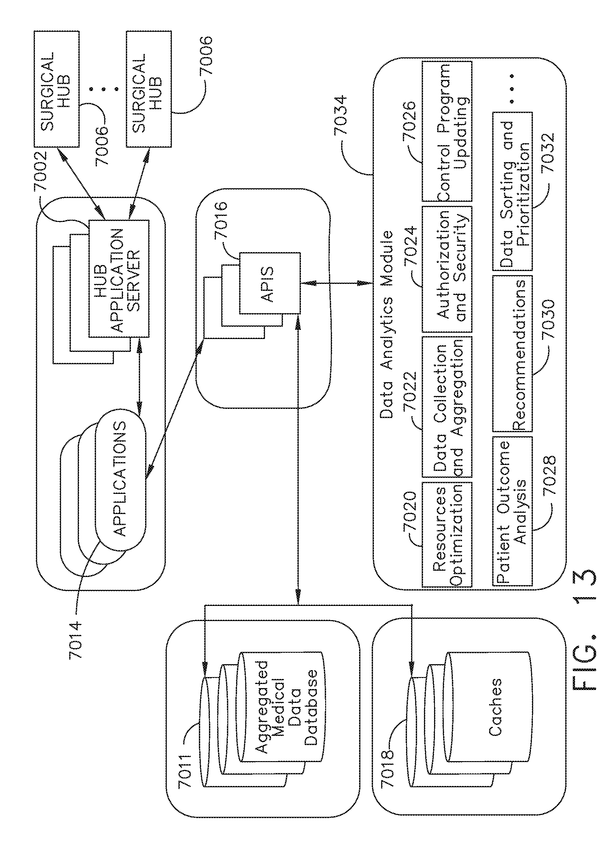
D00013
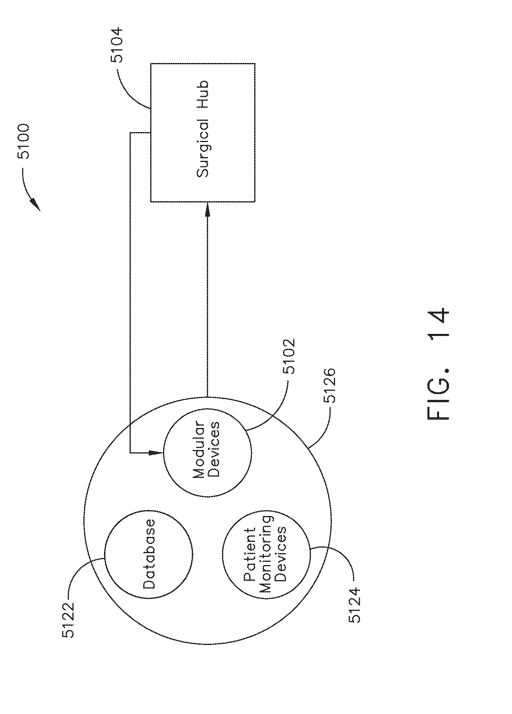
D00014
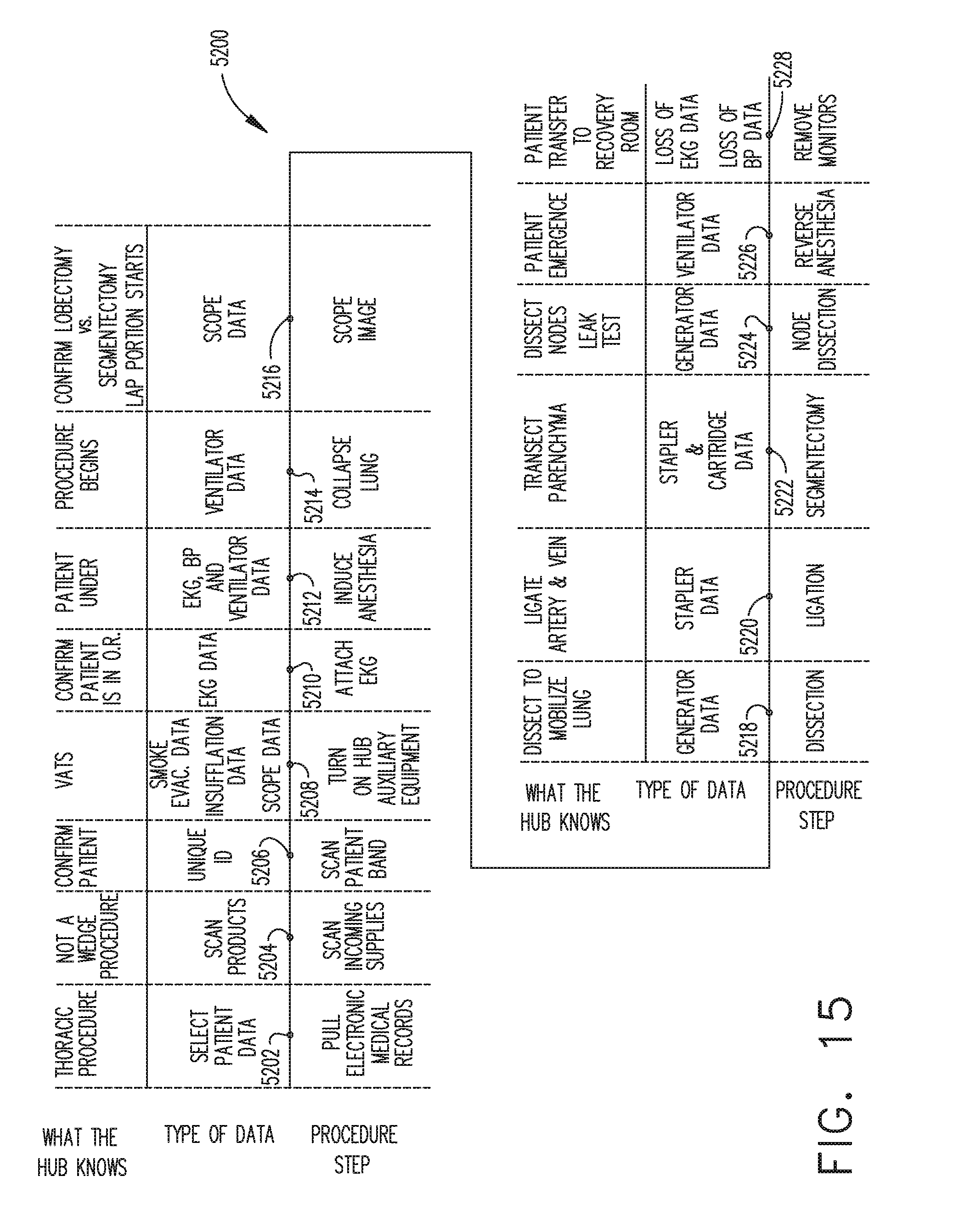
D00015
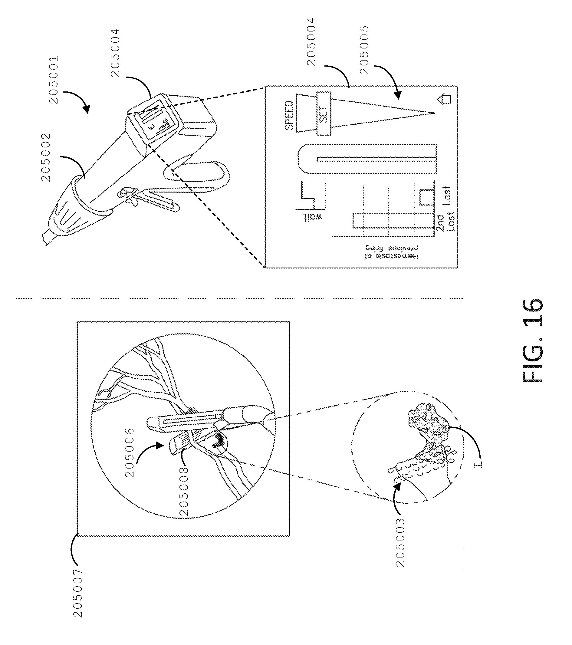
D00016
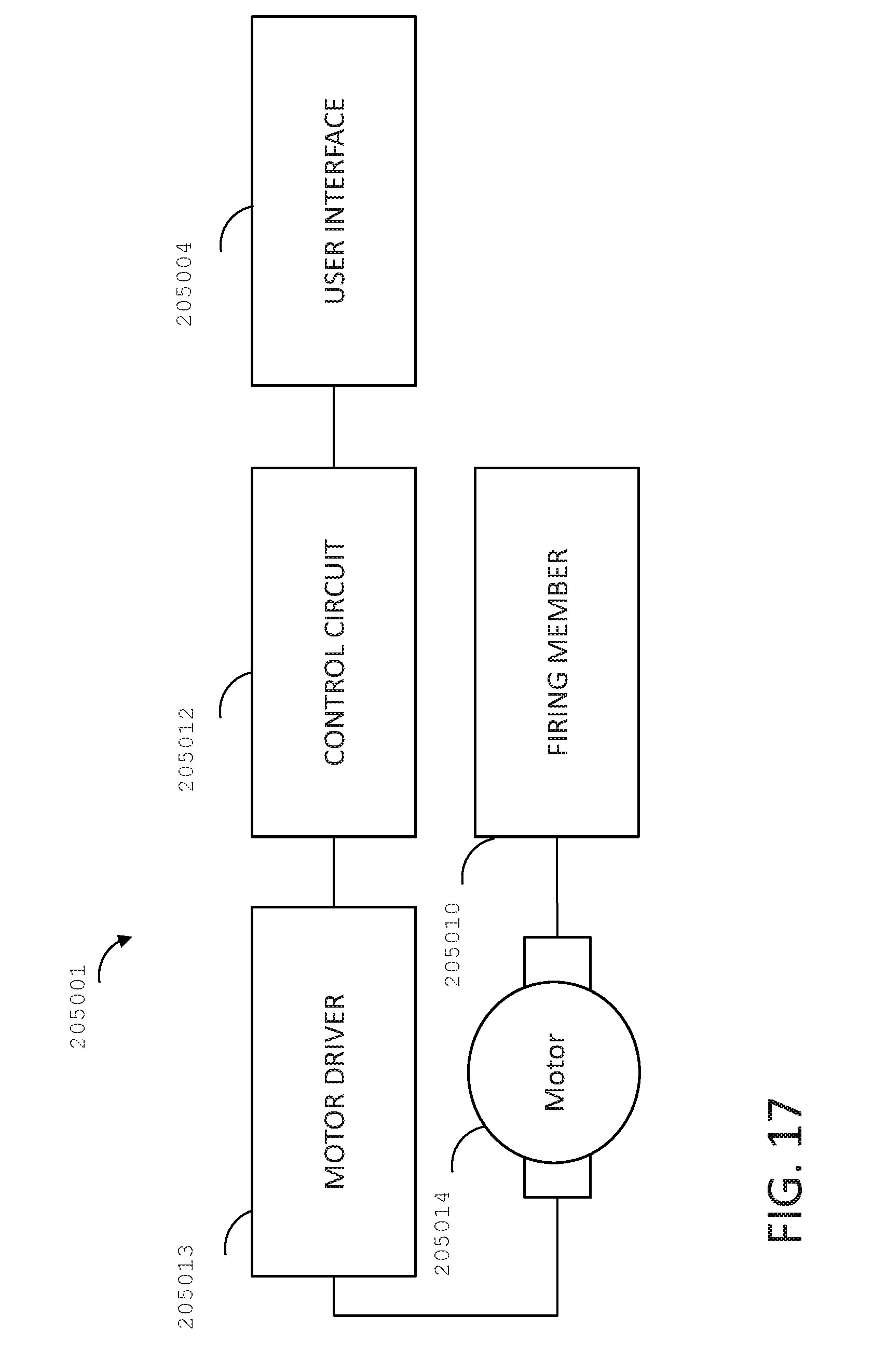
D00017
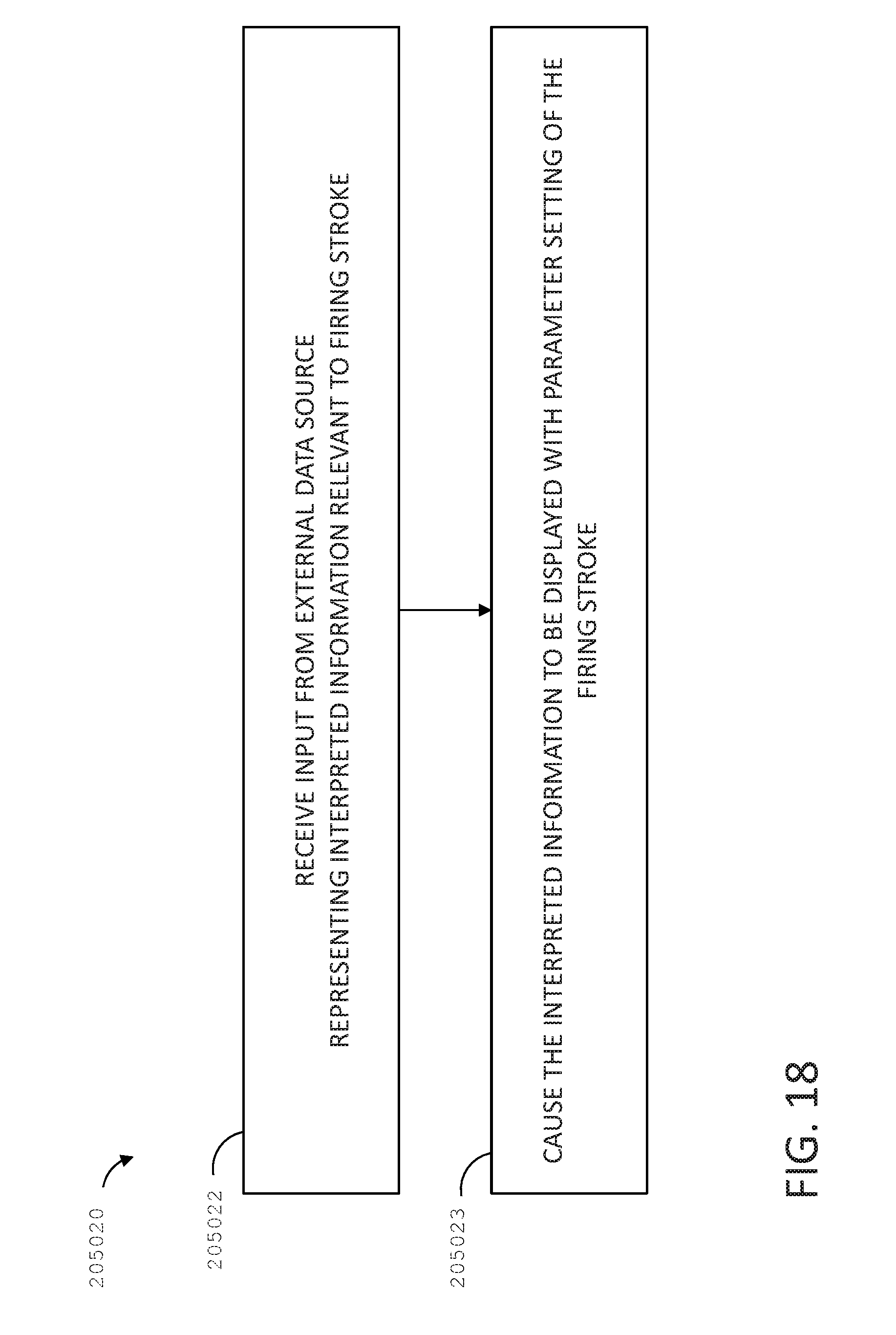
D00018
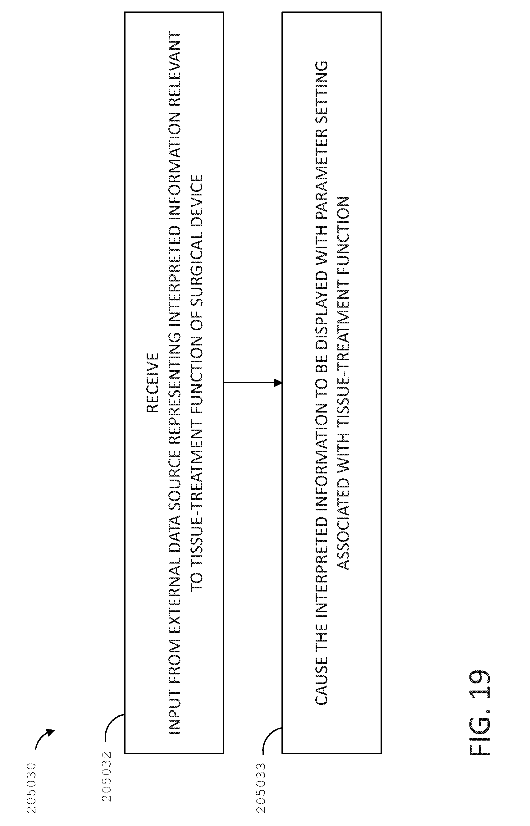
D00019
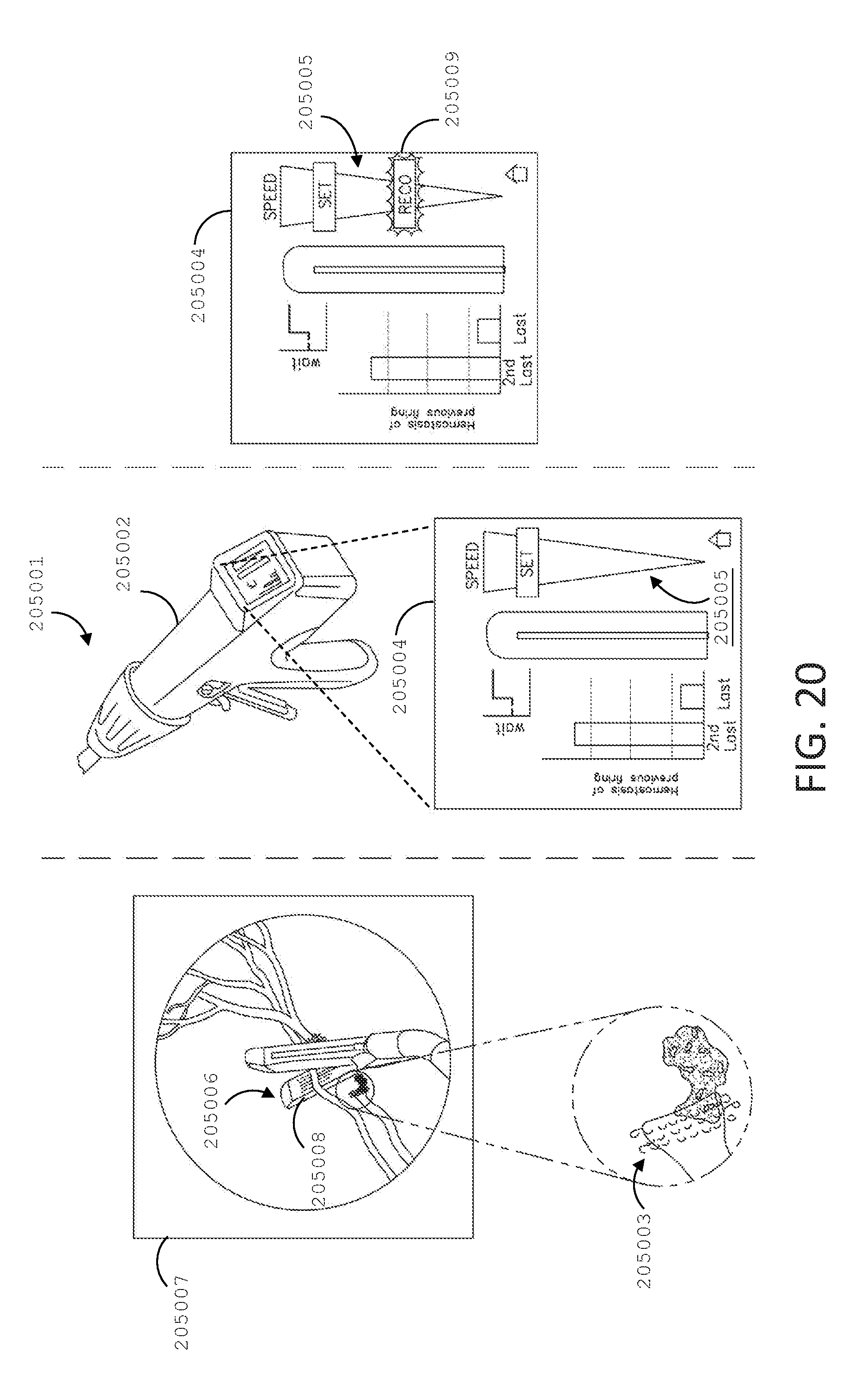
D00020
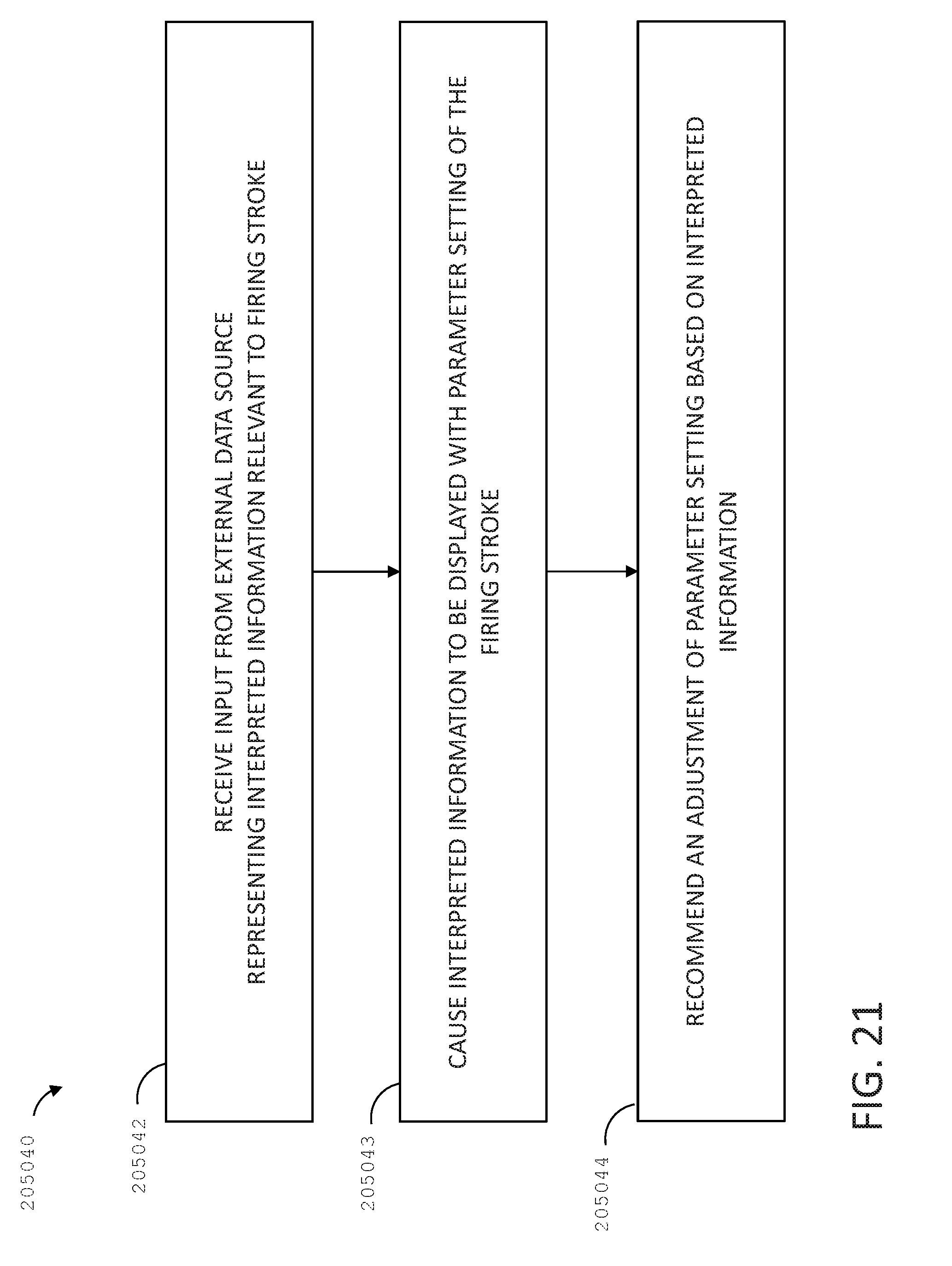
D00021
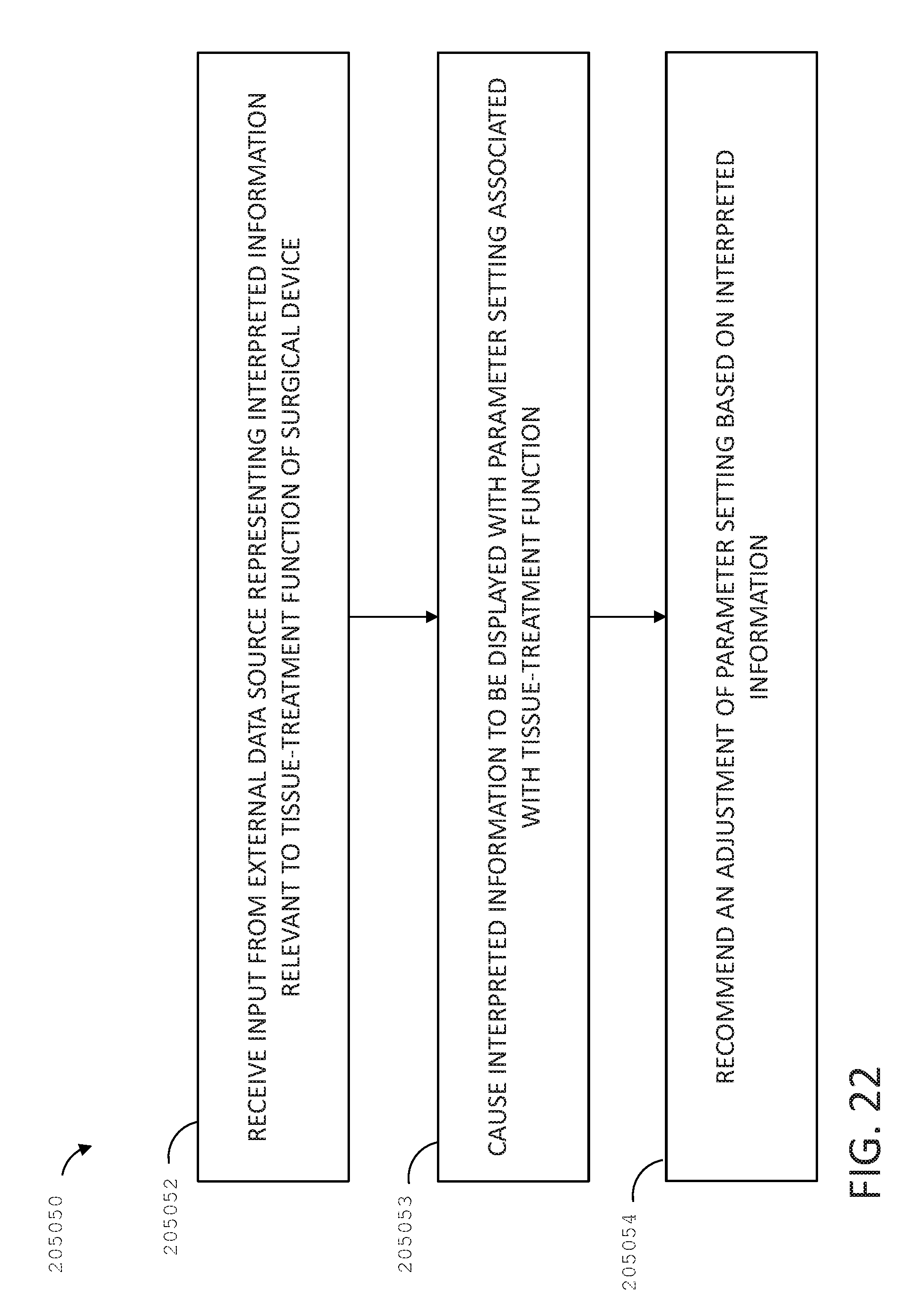
D00022
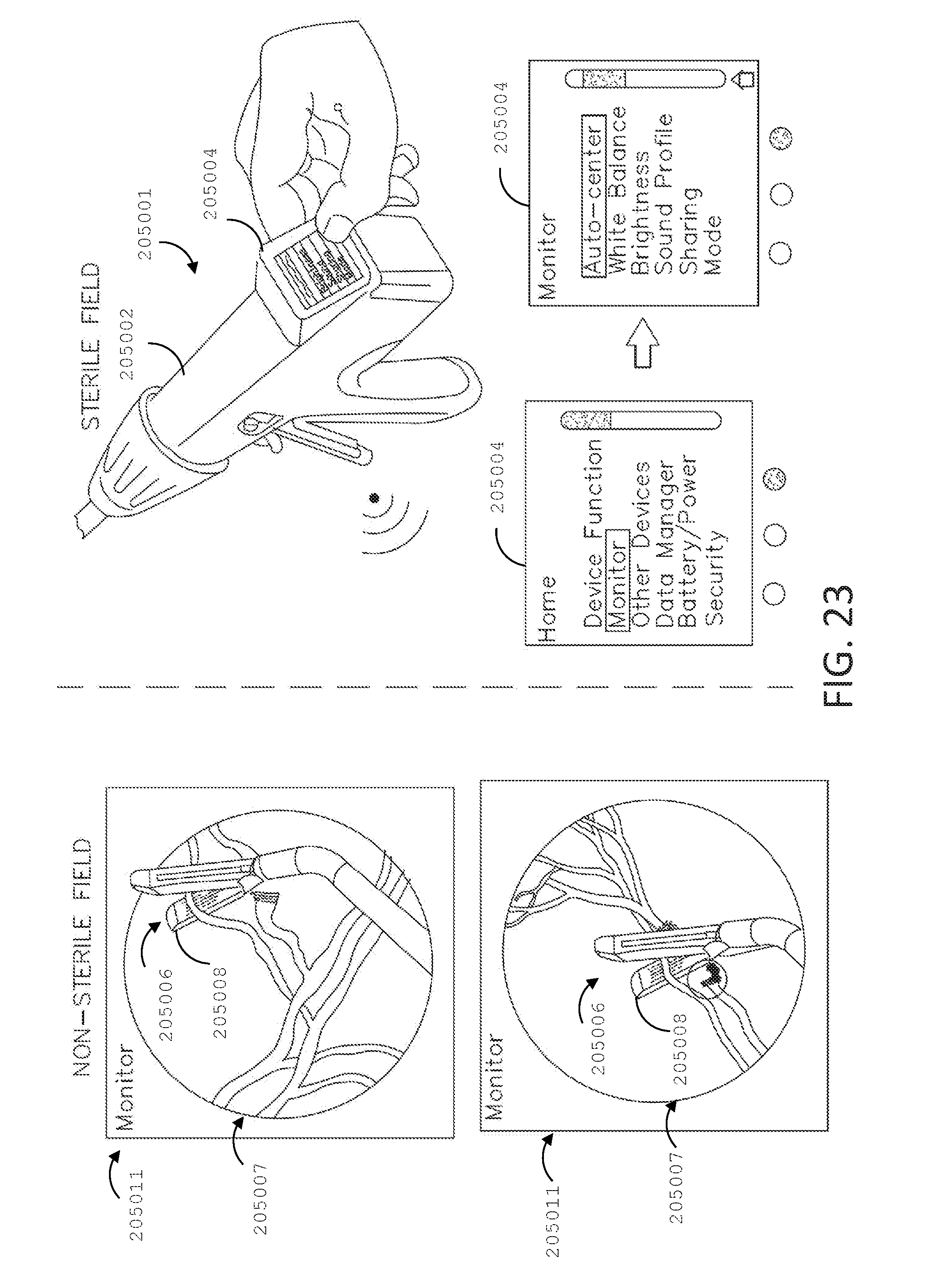
D00023
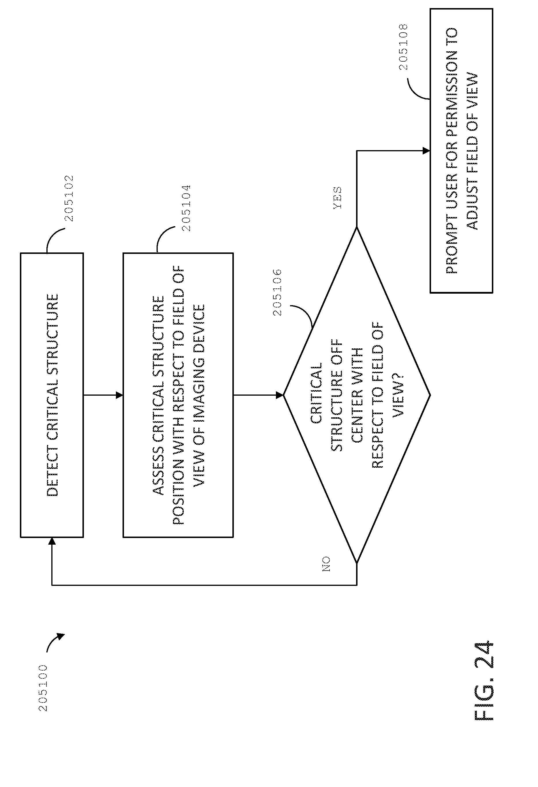
D00024
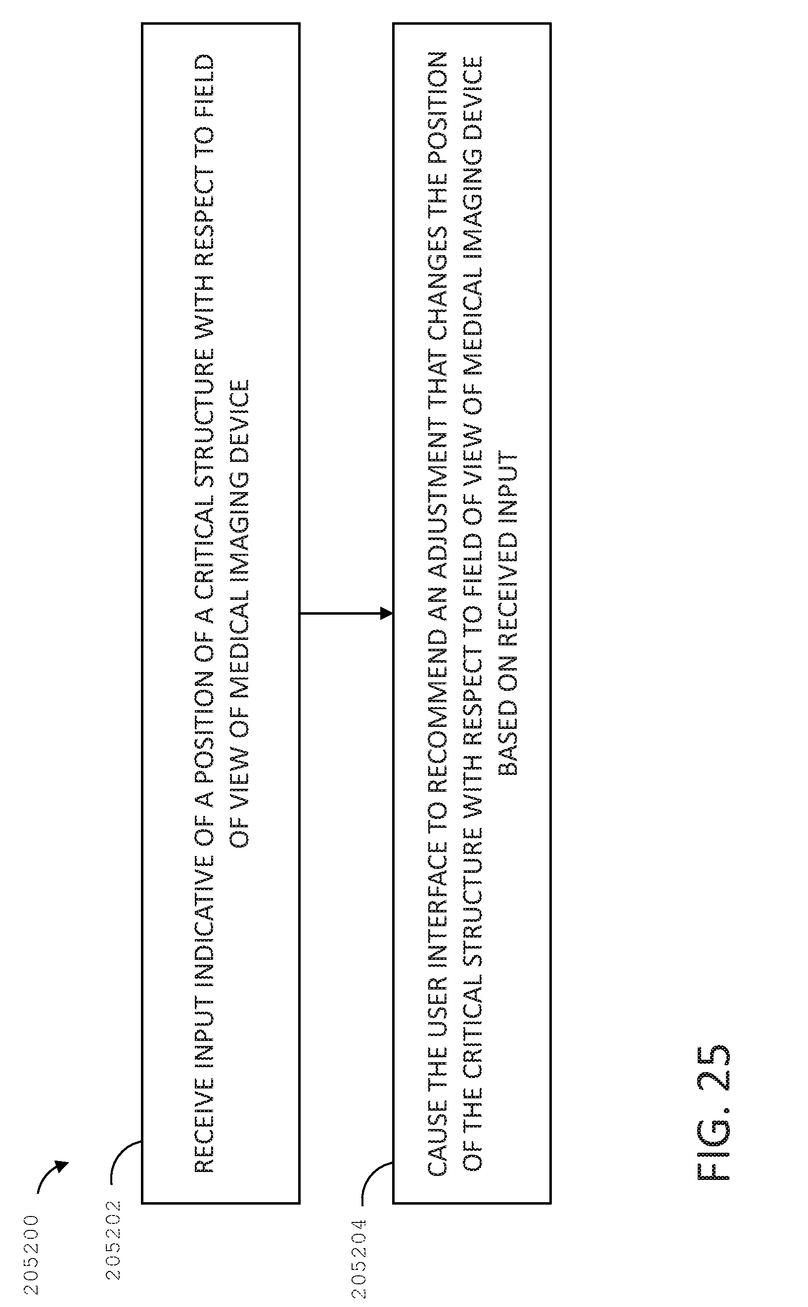
XML
uspto.report is an independent third-party trademark research tool that is not affiliated, endorsed, or sponsored by the United States Patent and Trademark Office (USPTO) or any other governmental organization. The information provided by uspto.report is based on publicly available data at the time of writing and is intended for informational purposes only.
While we strive to provide accurate and up-to-date information, we do not guarantee the accuracy, completeness, reliability, or suitability of the information displayed on this site. The use of this site is at your own risk. Any reliance you place on such information is therefore strictly at your own risk.
All official trademark data, including owner information, should be verified by visiting the official USPTO website at www.uspto.gov. This site is not intended to replace professional legal advice and should not be used as a substitute for consulting with a legal professional who is knowledgeable about trademark law.