Battery Terminal Cover
Tsuchiya; Takahiro
U.S. patent application number 16/228859 was filed with the patent office on 2019-06-27 for battery terminal cover. The applicant listed for this patent is Sumitomo Wiring Systems, Ltd.. Invention is credited to Takahiro Tsuchiya.
| Application Number | 20190199018 16/228859 |
| Document ID | / |
| Family ID | 66950710 |
| Filed Date | 2019-06-27 |


View All Diagrams
| United States Patent Application | 20190199018 |
| Kind Code | A1 |
| Tsuchiya; Takahiro | June 27, 2019 |
BATTERY TERMINAL COVER
Abstract
A battery terminal cover (1) is mounted on a battery (2) to be installed in a vehicle and includes a body (10) to be fixed to the battery (2), a movable portion (20) coupled to the body (10) via hinges (50) and rotatably displaceable to a shielding position to cover a screw member bolt (6) mounted on the battery (2) and an open position to be overlapped on the body portion (10), and a tool restricting portion (30) provided on the movable portion (20) and configured to restrict the rotation of a tool (T) by interfering with the tool before the tool rotated about the screw member (6) contacts the vehicle with the movable portion (20) set at the open position.
| Inventors: | Tsuchiya; Takahiro; (Yokkaichi, JP) | ||||||||||
| Applicant: |
|
||||||||||
|---|---|---|---|---|---|---|---|---|---|---|---|
| Family ID: | 66950710 | ||||||||||
| Appl. No.: | 16/228859 | ||||||||||
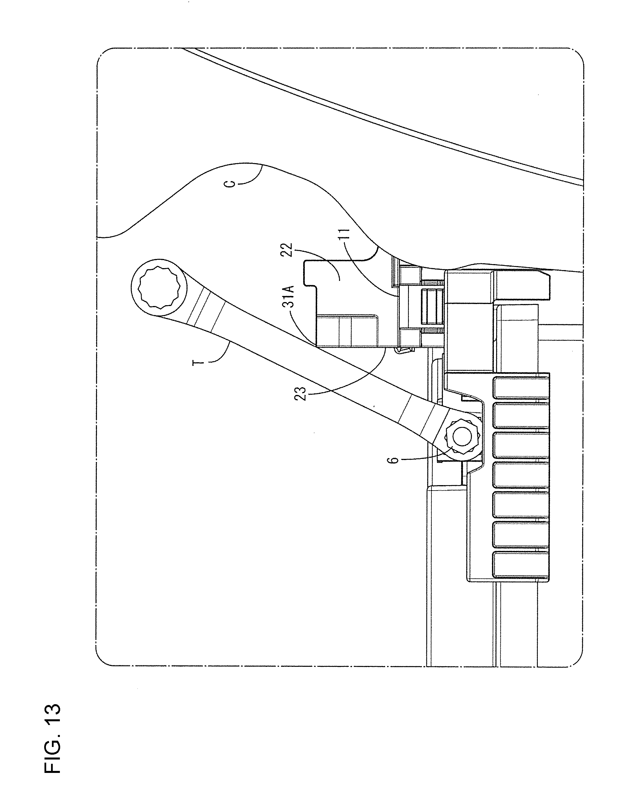
| Filed: | December 21, 2018 |
| Current U.S. Class: | 1/1 |
| Current CPC Class: | H01R 11/284 20130101; H01R 11/283 20130101; H01M 2/302 20130101; H01M 2/04 20130101; H01M 2/344 20130101; H01M 2220/20 20130101 |
| International Class: | H01R 11/28 20060101 H01R011/28; H01M 2/04 20060101 H01M002/04; H01M 2/30 20060101 H01M002/30; H01M 2/34 20060101 H01M002/34 |
Foreign Application Data
| Date | Code | Application Number |
|---|---|---|
| Dec 22, 2017 | JP | 2017-246291 |
Claims
1. A battery terminal cover (1) to be mounted on a battery (2) to be installed in a vehicle, comprising: a body (10) to be fixed to the battery (2); a movable portion (20) coupled to the body (10) via a hinge (50), the movable portion (20) being rotatably displaceable to a shielding position to cover a screw member (6) mounted on the battery (2) and an open position to be overlapped on the body (10); and a tool restricting portion (30) provided on the movable portion (20), the tool restricting portion (30) restricting the rotation of a tool (T) by interfering with the tool (T) before the tool (T) rotated about the screw member (6) contacts the vehicle with the movable portion (20) at the open position.
2. The battery terminal cover (1) of claim 1, wherein: the body (10) includes a fixed ceiling plate (11) coupled to the hinge (50); the movable portion (20) includes a movable ceiling plate (21) coupled to the hinge (50); the tool restricting portion (30) is provided at a position projected farther in an axial direction of the hinge (50) than the movable portion (20); and at least one of the movable ceiling plate (21) and the fixed ceiling plate (11) includes a lateral displacement restricting portion (141) lockable to the other when the movable portion (20) is at the open position.
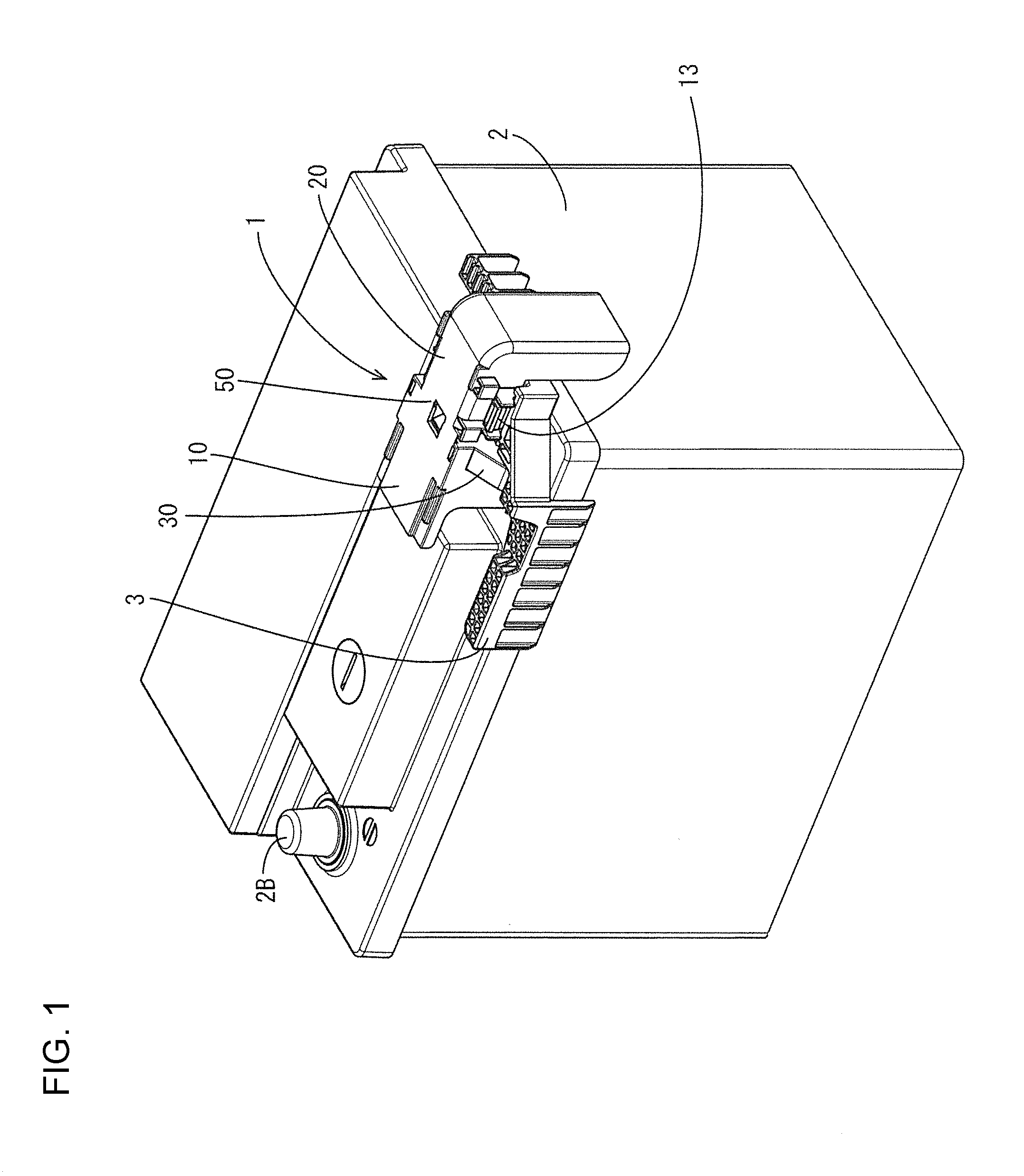
3. The battery terminal cover (1) of claim 2, wherein: the movable portion (20) further includes a movable side plate (22) projecting in a direction separating from the body (10) at the open position; and the tool restricting portion (30) is provided on the movable side plate (22).
4. The battery terminal cover (1) of claim 3, further comprising an angle setting portion (170) configured to support the movable portion (20) at an acute angle to the body (10) to separate the movable portion (20) from the body (10) when the movable portion (20) is set at the open position.
5. The battery terminal cover (1) of claim 3, wherein: the body (10) includes a fixed ceiling plate (11) coupled to the hinge (50); the movable portion (20) includes a movable ceiling plate (21) coupled to the hinge (50); the tool restricting portion (30) projects farther in an axial direction of the hinge (50) than the movable portion (20); at least one of the movable ceiling plate (21) and the fixed ceiling plate (11) includes a lateral displacement restricting portion (141) lockable to the other when the movable portion (20) is set at the open position; and the angle setting portion (170) projecting up from the body (10) and the lateral displacement restricting portion (141) is provided on an upper end part of the angle setting portion (170).
6. The battery terminal cover (1) of claim 1, wherein: the movable portion (20) further includes a movable side plate (22) projecting in a direction separating from the body (10) at the open position; and the tool restricting portion (30) is provided on the movable side plate (22).
7. The battery terminal cover (1) of claim 1, further comprising an angle setting portion (170) configured to support the movable portion (20) at an acute angle to the body (10) to separate the movable portion (20) from the body (10) when the movable portion (20) is set at the open position.
Description
BACKGROUND
Field of the Invention
[0001] This specification relates to a battery terminal cover.
Related Art
[0002] Japanese Unexamined Patent Publication No. 2010-108785 discloses a cover for protecting a terminal projecting from a battery. The battery connection terminal protection cover includes a fuse unit protecting portion disposed along a side surface of the battery and a terminal protecting portion coupled to the fuse unit protecting portion via a hinge. A battery post projects up from the upper surface of the battery and an electrical connection part is wound and fastened by a bolt on the outer periphery of the battery post. The terminal protecting portion can cover the battery post and the bolt with a clearance formed between the terminal protecting portion and the battery post. The bolt can be rotated up about the vicinity of the hinge to be opened for an operation such as battery exchange.
[0003] In this configuration, the terminal protecting portion is opened for battery exchange or the like, and the bolt is loosened using a tool. However, the rotated tool may hit a vehicle body and damage the vehicle body.
SUMMARY
[0004] This specification relates to a battery terminal cover to be mounted on a battery to be installed in a vehicle. The battery terminal cover includes a body to be fixed to the battery. A movable portion is coupled to the body via a hinge. The movable portion is rotatably displaceable to a shielding position to cover a screw mounted on the battery and an open position to overlap the body. A tool restricting portion is provided on the movable portion and restricts rotation of a tool by interfering with the tool before the tool rotated about the screw contacts the vehicle when the movable portion is open. According to this configuration, the tool rotated about the screw contacts the tool restricting portion to restrict any further rotation. Thus, the tool comes will not contact and damage the vehicle.
[0005] The body includes a fixed ceiling plate coupled to the hinge, and the movable portion includes a movable ceiling plate coupled to the hinge. The tool restricting portion may project farther in an axial direction of the hinge than the movable portion, and at least one of the movable ceiling plate and the fixed ceiling plate portion may include a lateral displacement restricting portion that is lockable to the other when the movable portion is at the open position. pressing force from the tool may be transferred from the tool restricting portion to the movable portion. This force could displace the movable portion rotationally about the hinge and the movable portion may be displaced from the body. However, according to this configuration, the lateral displacement restricting portion is provided on at least one of the movable ceiling plate and the fixed ceiling plate and locks the other. Thus, a lateral displacement of the movable portion is restricted. In this way, rotation of the tool is restricted reliably by preventing displacement of the tool restricting portion.
[0006] The movable portion may include a movable side plate projecting in a direction separating from the body at the open position, and the tool restricting portion may be on the movable side plate. According to this configuration, the tool restricting portion is at a position separated from the body according to a projecting height of the movable side plate when the movable portion is at the open position. Thus, the tool restricting portion can be arranged at a desired position in a height direction from the body.
[0007] The battery terminal cover may further include an angle setting portion configured to support the movable portion at an acute angle to the body to separate the movable portion from the body when the movable portion is at the open position. The tool restricting portion is arranged according to an angle at which the movable portion is supported and can be arranged at a desired position.
[0008] The angle setting portion may project up from the body, and the lateral displacement restricting portion may be on an upper part of the angle setting portion. Accordingly, the angle setting portion can double as the lateral displacement restricting portion, and the number of parts can be reduced.
BRIEF DESCRIPTION OF DRAWINGS
[0009] FIG. 1 is a perspective view of a battery terminal cover according to a first embodiment when viewed from behind.
[0010] FIG. 2 is a perspective view of a ground terminal group and a battery terminal when viewed from behind.
[0011] FIG. 3 is a perspective view of the battery terminal cover with a movable portion set at a shielding position when viewed from behind.
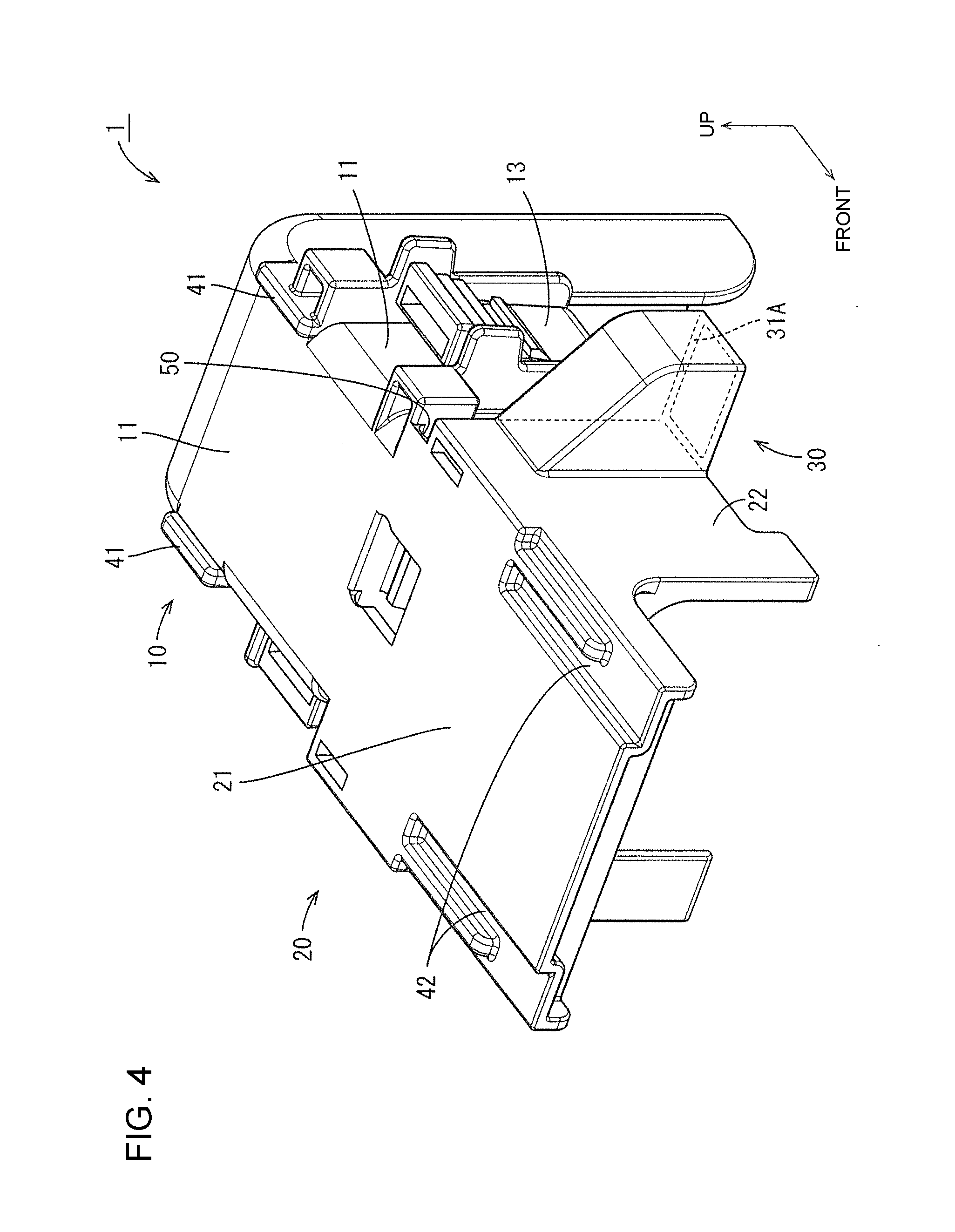
[0012] FIG. 4 is a perspective view of the battery terminal cover with the movable portion set at the shielding position when viewed from front.
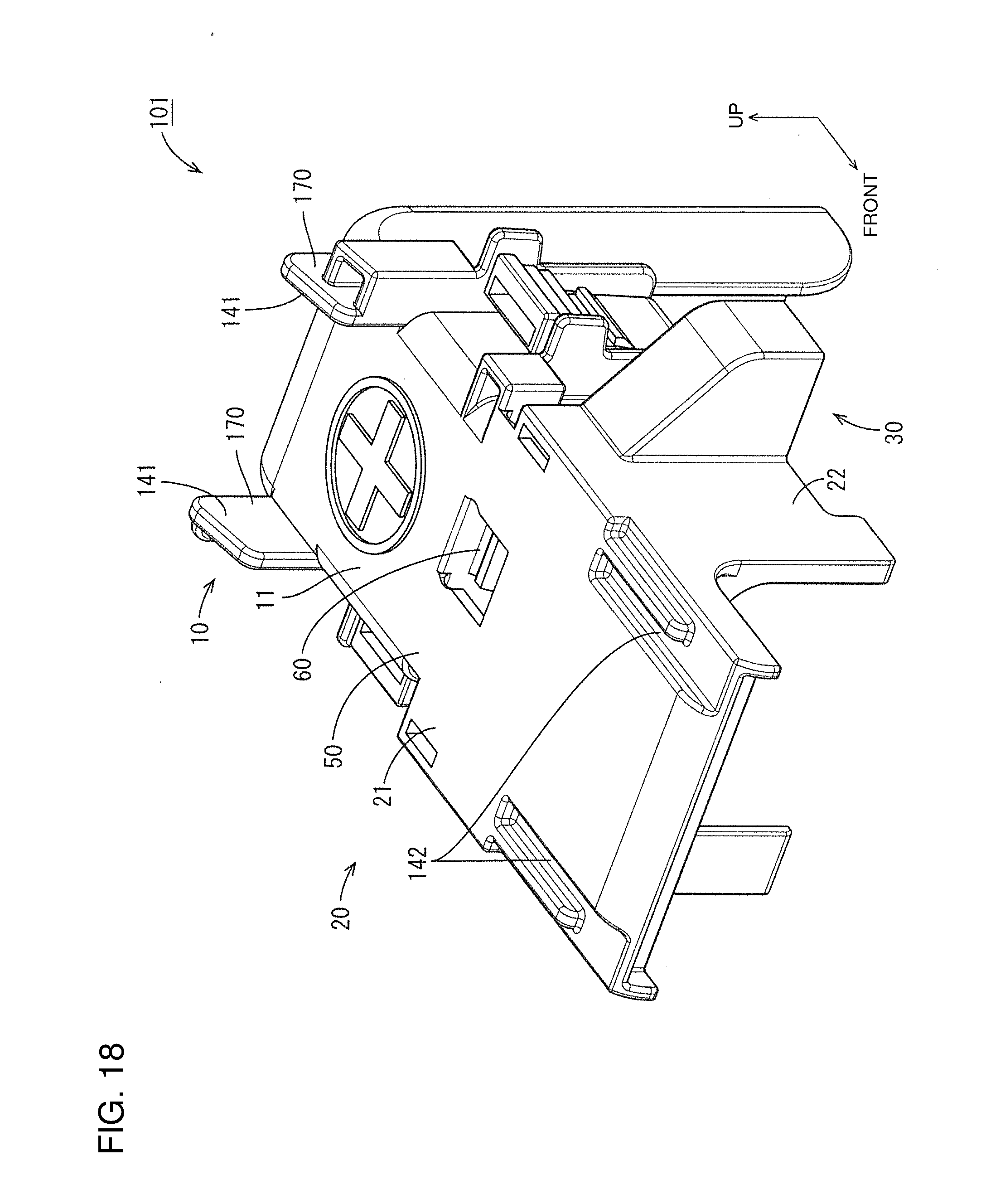
[0013] FIG. 5 is a side view of the battery terminal cover with the movable portion set at the shielding position.
[0014] FIG. 6 is a perspective view of the battery terminal cover with the movable portion set at the shielding position when viewed from behind.
[0015] FIG. 7 is a bottom view of the battery terminal cover with the movable portion set at the shielding position.
[0016] FIG. 8 is a plan view of the battery terminal cover with the movable portion set at the shielding position.
[0017] FIG. 9 is a front view of the battery terminal cover with the movable portion set at the shielding position.
[0018] FIG. 10 is a perspective view of the battery terminal cover with the movable portion set at an open position.
[0019] FIG. 11 is a perspective view of the battery terminal cover with the movable portion set at the open position.
[0020] FIG. 12 is a side view of the battery terminal cover with the movable portion set at the open position.
[0021] FIG. 13 is a side view showing a state where a tool is being used in a vehicle.
[0022] FIG. 14 is a front view showing the state where the tool is being used in the vehicle.
[0023] FIG. 15A is a back view showing a state where the tool is being used and FIG. 15B is an enlarged back view of the circled region in FIG. 15A.
[0024] FIG. 16 is a section along A-A of FIG. 14.
[0025] FIG. 17 is a perspective view of a battery terminal cover of a second embodiment when viewed from behind.
[0026] FIG. 18 is a perspective view of the battery terminal cover with a movable portion set at a shielding position when viewed from front.
[0027] FIG. 19 is a side view of the battery terminal cover with the movable portion set at the shielding position.
[0028] FIG. 20 is a plan view of the battery terminal cover with the movable portion set at the shielding position.
[0029] FIG. 21 is a section showing a state where the movable portion is set at an open position.
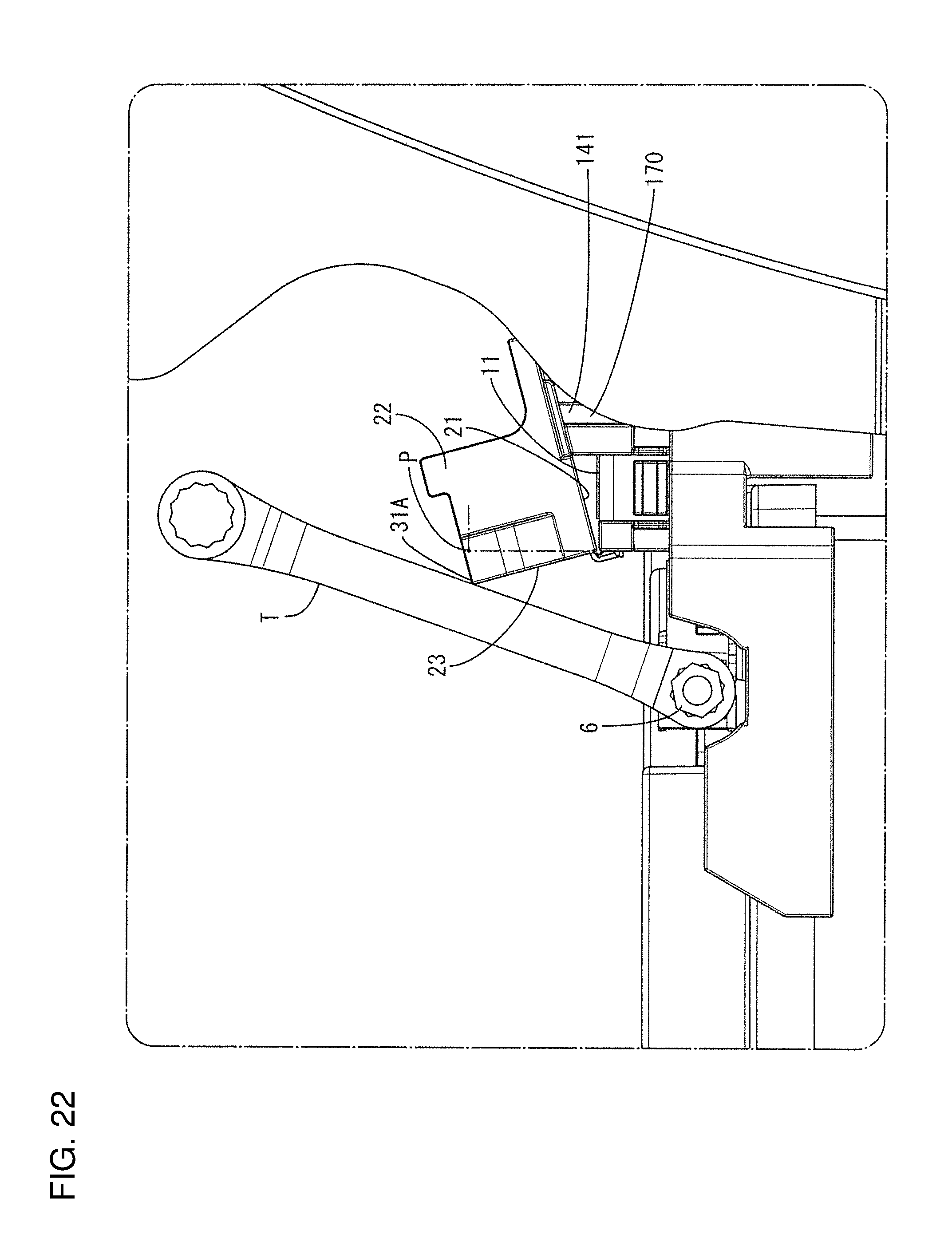
[0030] FIG. 22 is a side view showing a state where a tool is being used in a vehicle.
[0031] FIG. 23 is a back view showing the state where the movable portion is set at the open position.
DETAILED DESCRIPTION
[0032] A first embodiment is described with reference to FIGS. 1 to 16. A battery terminal cover 1 of this embodiment is mounted on an upper surface side of a battery 2 for a vehicle, as shown in FIG. 1, to cover and protect a positive electrode 2A and its periphery shown in FIG. 2. In the following description, an upper side in a state shown in FIG. 2 is referred to as an upper side and a side near a negative electrode 2B is referred to as a front in the battery terminal cover 1.
[0033] As shown in FIG. 2, a battery terminal 5, a bolt 6 (screw member) for fixing the battery terminal 5 to the positive electrode 2A and an L-shaped terminal 7 are mounted around the positive electrode 2A. The L-shaped terminal 7 extends from the upper surface to a side surface of the battery terminal 2 to have an L shape. The battery terminal 5 is a long and narrow strip that is wound on the positive electrode 2A. Screw holes are arranged in front of the positive electrode 2A and penetrate near both ends of the battery terminal 5 on the side of the positive electrode 2A. The bolt 6 is screwed into screw holes and an axis thereof is oriented in a lateral direction. A lower part of the L-shaped terminal 7 is caulked and crimped to an unillustrated wire. The L-shaped terminal 7 is positioned with respect to the battery 2 by being fit into a rotation stopping resin component 3.
[0034] The battery terminal cover 1 is divided into two parts across hinges 50 at a substantially half position in a front-rear direction, as shown in FIGS. 3 to 5. In the following description, the part behind the hinges 50 is referred to as a body 10 and the part before the hinges 50 is referred to as a movable portion 20. Further, a part of the body 10 that covers the L-shaped terminal 7 and its periphery from above is referred to as a fixed ceiling plate 11 and parts laterally covering the L-shaped terminal 7 and its periphery are referred to as fixed side plates 12. A part of the movable portion 20 covering the bolt 6 and its periphery from above is referred to as a movable ceiling plate 21 and parts laterally covering the bolt 6 are referred to as movable side plates 22.
[0035] The fixed ceiling plate 11 and the movable ceiling plate 21 are coupled by left and right hinges 50 having axes oriented in a lateral direction and a spring 60 is provided between the hinges 50, as shown in FIGS. 3, 5 and 6. The spring 60 has a bent shape to project down. The spring 60 is a reaction force spring and transitions into an extended state and a bent state to leap by biasing an external force due to a resilient force thereof.
[0036] As shown in FIGS. 5 and 6, each fixed side plate 12 of the body 10 is substantially L-shaped when viewed laterally. A mounting claw 13 extends down on each fixed side plate 12. As shown in FIG. 1, each fixed side plate 12 is arranged to contact the upper surface and the side surface of the rotation stopping resin component 3 and each mounting claw 13 is fit into a mount receiving portion 3A (see FIG. 2) provided in the rotation stopping resin component 3 so that the body 10 is locked to the rotation stopping resin component 3.
[0037] The movable portion 20 can be arranged at a shielding position where the bolt 6 is covered, as shown in FIG. 1, and at an open position where the bolt 6 can be exposed to the outside, as shown in FIG. 10, by a biasing force of the spring 60. With the movable portion 20 set at the open position, the movable ceiling plate 21 is in surface contact with the fixed ceiling plate 11, as shown in FIG. 16, and the movable side plates 22 project in a direction separating from the fixed ceiling plate 11. At the time of maintenance, such as an exchange for the battery 2, the movable portion 20 is at the open position to expose the bolt 6 and the bolt 6 can be screwed or unscrewed using a tool T.
[0038] A relatively large torque is necessary to screw the bolt 6. Thus, the tool T has a long handle in many cases. However, if a handle of such a tool T is rotated about the bolt 6 in a vehicle C, the tip of the tool T may contact the vehicle C and damage the vehicle C.
[0039] Accordingly, the battery terminal cover 1 has a tool restricting portion 30 projecting into a rotation locus extending until the tool T contacts the vehicle C and is configured to restrict the rotation of the tool T by interfering with the tool T before the tool T contacts the vehicle C.
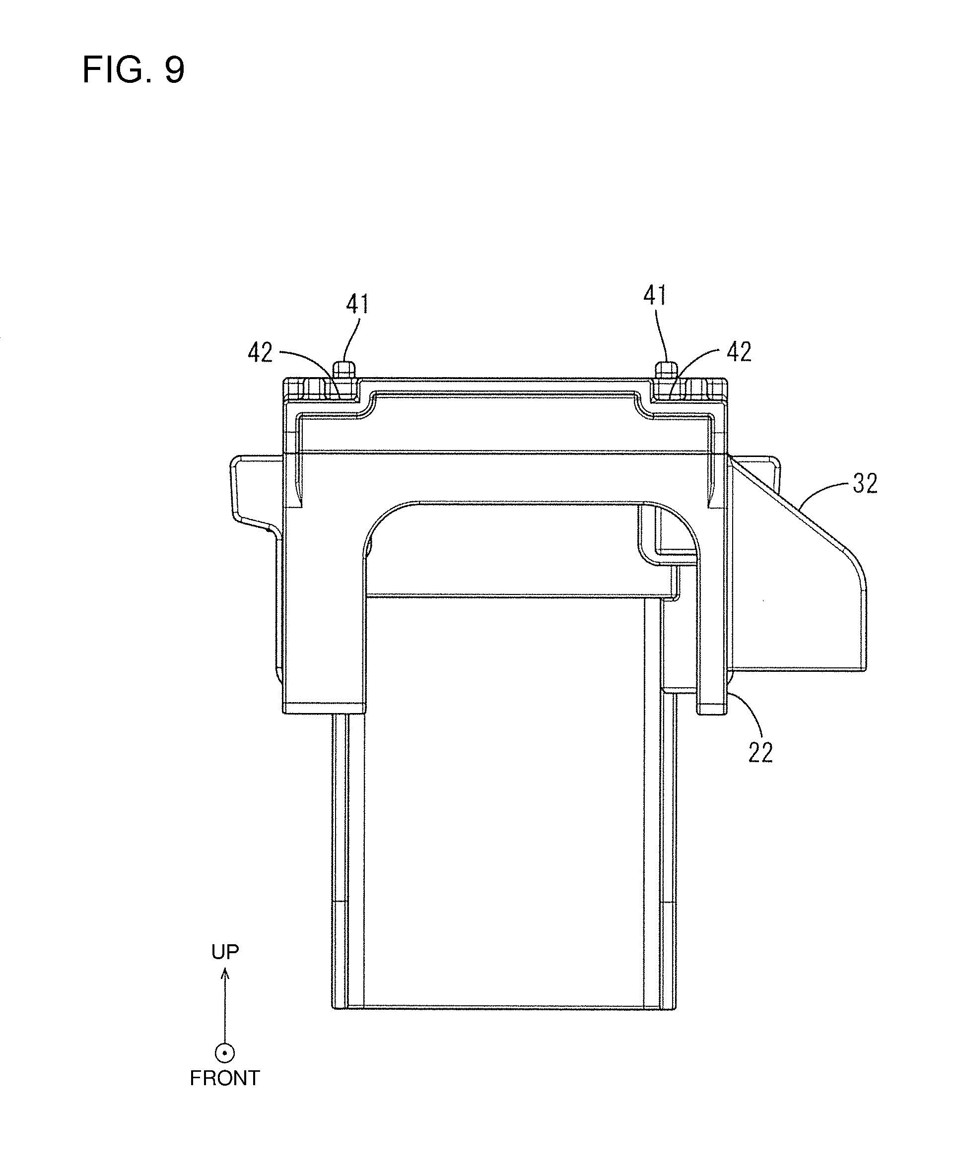
[0040] The tool restricting portion 30 extends toward an outer surface side of one of the movable side plates 22, as shown in FIGS. 3 and 4, and has a box shape open down, as shown in FIG. 7. A rear wall 31 of the tool restricting portion 30 is flush with a back plate 23 provided on the rear end of the movable portion 20, as shown in FIGS. 3 and 7. A lower end 31A of the rear wall 31 is flush with the lower end (upper end in a state of FIG. 10) of the movable side plate 22, as shown in FIGS. 4 and 10. A ceiling wall 32 of the tool restricting portion 30 extends obliquely down at an angle of about 45.degree. with respect to the movable side plate 22, as shown in FIG. 9. A lower end part of the rear wall 31 of the tool restricting portion 30 is referred to below as a rotation restricting end 31A.
[0041] In the state shown in FIG. 1 where the movable portion 20 is at the shielding position, the tool restricting portion 30 is accommodated with the rotation restricting end 31A fit between the battery terminal 5 and the rotation stopping resin component 3.
[0042] With the movable portion 20 set at the open position, the rotation restricting end 31A is above the front end of the fixed ceiling plate 11, as shown in FIG. 13. If the tool T is rotated about the bolt 6 in this state, the rotation restricting end 31A interferes with the handle of the tool T to restrict further rotation. A pressing force received by the rotation restricting end 31A from the tool T is transferred to the movable ceiling plate 21 mainly via the movable side plate 22 and the back plate 23 and is transferred to the body 10 via the movable ceiling plate 21.
[0043] Note that left and right auxiliary ribs 24 are provided in parallel to the back plate 23 on inner sides of the movable side plates 22, as shown in FIGS. 10 and 11. As shown in FIG. 10, one end of the auxiliary rib 24 is coupled to the movable side plate 22 and the lower end thereof is coupled to the movable ceiling plate 21. In this way, the auxiliary rib 24 supports the movable side plate 22 from the inner side to prevent deflection and deformation of the movable side plate 22.
[0044] An operation of rotating the bolt 6 is performed in the vehicle with a limited space, and a tool T bent from a head to a handle (so-called offset type) as shown in FIG. 14 may be used. Assuming this in this embodiment, the tool restricting portion 30 is provided at a laterally outer side of the movable side plate 22 (i.e. at a position projected farther in an axial direction of the hinges 50 than the movable portion 20) as described above.
[0045] In this configuration, the tool T contacts and presses the rotation restricting end 31A at the laterally outer side of the movable side plate 22, as shown in FIGS. 14 and 15(A). Thus, a pressing force acts to displace laterally the movable ceiling plate 21. Further, the hinges 50 are strips of synthetic resin and may be deformed by an external force. Accordingly, the movable ceiling plate 21 may laterally displace to rotate about the hinges 50 by the pressing force from the tool T, and the tool restricting portion 30 may deviate from a desired position to allow the tool T to contact the vehicle C.
[0046] To prevent such contact, the battery terminal cover 1 has a lateral displacement restricting portion 40 for restricting a lateral displacement of the movable ceiling plate 21, as shown in FIGS. 15(A) and 15(B). The lateral displacement restricting portion 40 has left and right lateral displacement restricting ribs 41 on the fixed ceiling plate 11 and left and right lateral displacement restricting recesses 42 provided in the movable ceiling plate 21.
[0047] The lateral displacement restricting ribs 41 project up on both lateral ends of the fixed ceiling plate 11, as shown in FIG. 4, and extend in the front-rear direction from the rear end position of each mounting claw 13 to the rear end of the fixed ceiling plate 11, as shown in FIG. 5.
[0048] As shown in FIG. 4, the lateral displacement restricting recesses 42 are formed by recessing areas of the movable ceiling plate 21 near both lateral ends and extending down from a position before the tool restricting portion 30 to the front end. The movable ceiling plate 21 has a reinforcing wall 25 coupling the left and right movable side plates 22, as shown in FIG. 11, and the reinforcing wall 25 intersects the both lateral displacement restricting recesses 42 when viewed from below through the lower surface, as shown in FIG. 7.
[0049] As shown in FIG. 15(B), a width (lateral dimension) of the lateral displacement restricting rib 41 is set to fit into the lateral displacement restricting recess 42. A projecting height of the lateral displacement restricting rib 41 from the fixed ceiling plate 11 is equal to or shorter than a depth of the lateral displacement restricting recess 42. In this way, at the open position of the movable portion 20, the lateral displacement restricting ribs 41 are fit into the lateral displacement restricting recesses 42 and lock to the lateral displacement restricting recesses 42, as shown in FIG. 15(B), and the movable ceiling plate 21 is in surface contact with the fixed ceiling plate 11, as shown in FIG. 16.
[0050] If the movable portion 20 is going to be laterally displaced with respect to the body portion 10 by a pressing force transferred from the tool T to the tool restricting portion 30, the lateral displacement restricting recesses 42 are locked to the lateral displacement restricting ribs 41 to restrict lateral displacement of the movable portion 20.
[0051] As described above, the battery terminal cover 1 is mounted on the battery 2 to be installed in the vehicle and includes the body 10 to be fixed to the battery 2, the movable portion 20 coupled to the body 10 via the hinges 50 and rotationally displaceable to the shielding position to cover the screw member (bolt 6) mounted on the battery 2 and the open position to be overlapped on the body 10, and the tool restricting portion 30 provided on the movable portion 20 and configured to restrict the rotation of the tool T by interfering with the tool T before the tool T rotated about the screw member 6 contacts the vehicle C with the movable portion 20 set at the open position. According to this configuration, the tool T rotated about the screw member 6 contacts the tool restricting portion 30 to restrict any further rotation. Thus, the tool T cannot contact and damage the vehicle C.
[0052] The body 10 includes the fixed ceiling plate 11 coupled to the hinges 50, the movable portion 20 includes the movable ceiling plate 21 coupled to the hinges 50, the tool restricting portion 30 projected farther in the axial direction of the hinges 50 than the movable portion 20, and at least one of the movable ceiling plate 21 and the fixed ceiling plate 11 includes the lateral displacement restricting portion 40 lockable to the other when the movable portion 20 is at the open position.
[0053] Since the tool restricting portion 30 projects farther in the axial direction of the hinges 50 than the movable portion 20 in this configuration, a pressing force from the tool T may be transferred from the tool restricting portion 30 to the movable portion 20 and may act in the direction to rotationally displace the movable portion 20 about the hinges 50 and the movable portion 20 may be displaced from the body 10. However, according to this configuration, the lateral displacement restricting portion 40 on at least one of the movable ceiling plate 21 and the fixed ceiling plate 11 is locked to the other. Thus, a lateral displacement of the movable portion 20 is restricted. In this way, the rotation of the tool T can be reliably restricted by preventing a displacement of the tool restricting portion 30.
[0054] Further, the movable portion 20 includes the movable side plates 22 projecting in the direction separating from the body 10 at the open position, and the tool restricting portion 30 is provided on the movable side plate 22. According to this configuration, the tool restricting portion 30 is separated from the body 10 according to the projecting height of the movable side plate 22 when the movable portion 20 is at the open position, the tool restricting portion 30 can be arranged at a desired position in a height direction from the body 10.
[0055] A second embodiment is described with reference to FIGS. 17 to 23. A battery terminal cover 101 of the second embodiment differs from that of the first embodiment in that angle setting portions 170 are provided at the same positions as the lateral displacement restricting ribs 41 of the first embodiment to support a movable ceiling plate 21 at an acute angle to a fixed ceiling plate 11 and projecting end parts of the angle setting portions 170 double as lateral displacement restricting ribs 141. Components corresponding to those of the first embodiment are denoted by the reference signs of the first embodiment plus 100. The same configuration, functions and effects as those of the first embodiment are not described and the same components as those of the first embodiment are denoted by the same reference sings.
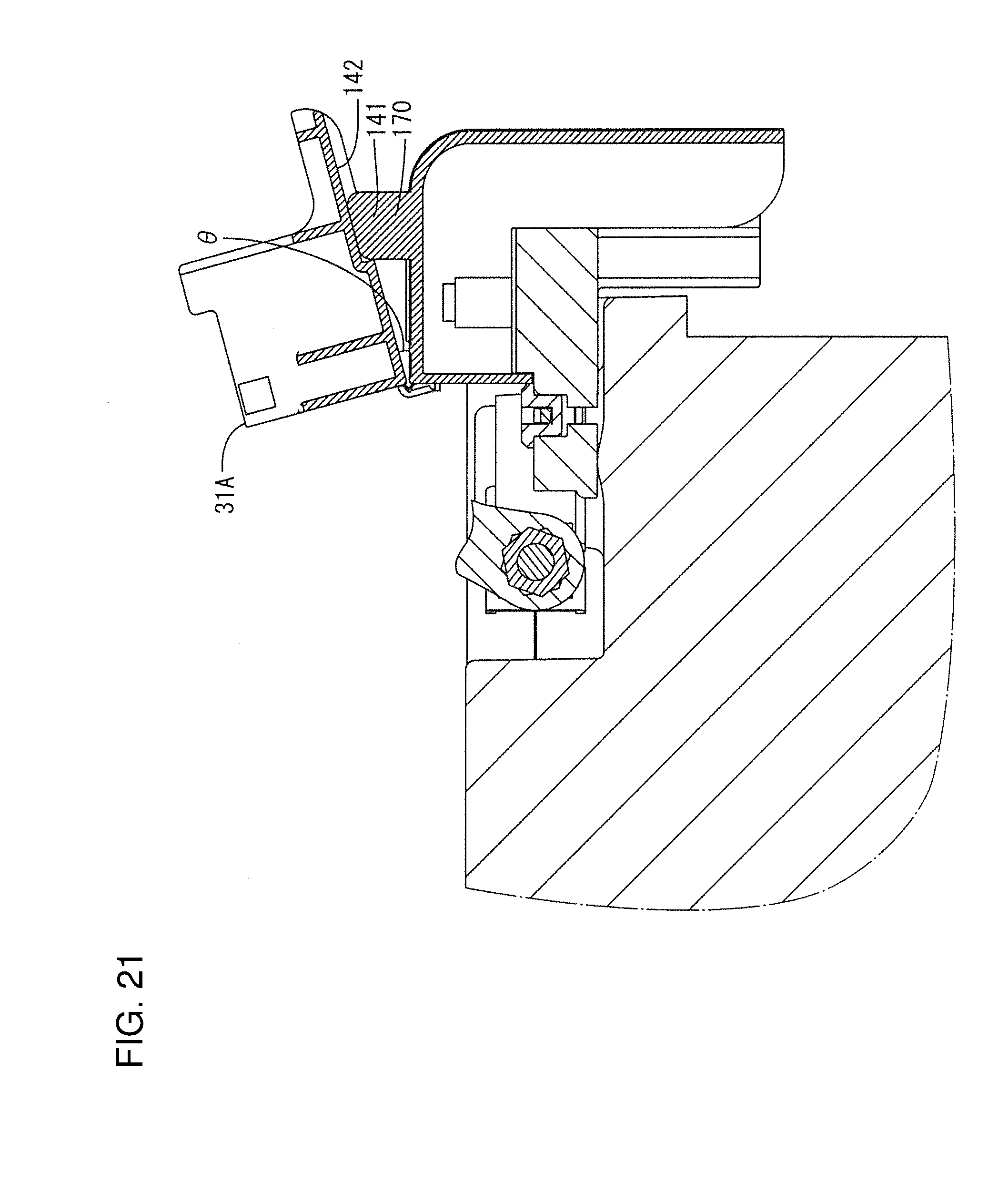
[0056] The angle setting portion 170 is shaped to project farther up than the lateral displacement restricting rib 41 of the first embodiment, as shown in FIG. 19, and the upper surface thereof is tapered with a front side higher than a rear side, as shown in FIG. 19.
[0057] With a movable portion 20 set at an open position, the upper surfaces of the angle setting portions 170 are in surface contact with bottom surfaces of lateral displacement restricting recesses 142, as shown in FIG. 21. In this way, the movable ceiling plate portion 21 is separated from the fixed ceiling plate 11 and supported at a predetermined angle .theta. to the fixed ceiling plate 11 with hinges 50 as a center, and inclined somewhat forward.
[0058] At this time, as shown in FIG. 22, a rotation restricting end portion 31A is arranged above and before a position P, which is above the front end of the upper surface of the fixed ceiling plate 11 by a height of a back plate 23. This causes a tool T to interfere with the rotation restricting end portion 31A at a position separated more from a vehicle C than in the first embodiment to restrict any further rotation.
[0059] Further, in this state, upper parts of the angle setting portions 170 are fit as the lateral displacement restricting ribs 141 into the lateral displacement restricting recesses 142 and can be locked to the lateral displacement restricting recesses 142, as shown in FIG. 23. In this way, a displacement of the tool restricting portion 30 is restricted as in the first embodiment.
[0060] As described above, the battery terminal cover 101 includes the angle setting portions 170 for supporting the movable portion 20 at an acute angle to the body 10 to separate the movable portion 20 from the body 10 when the movable portion 20 is open. According to this configuration, the tool restricting portion 30 is arranged according to a height position where the movable portion 20 is supported, the tool restricting portion 30 can be arranged at a desired position.
[0061] Further, the angle setting portions 170 project up from the body 10 and the lateral displacement restricting ribs 141 are on the upper end parts of the angle setting portions 170. According to this configuration, the angle setting portions 170 can double as the lateral displacement restricting portion 140. Thus, the angle setting portions 170 and the lateral displacement restricting portion 140 need not be provided separately.
[0062] The invention is not limited to the above described and illustrated embodiments and can be, for example, carried out as follows.
[0063] Although the tool restricting portion 30 projects up and the tool T comes into contact with the upper end part of the tool restricting portion 30 with the movable portion 20 set at the open position in the first and second embodiments, the shape of the tool restricting portion 30 is not limited to this. For example, if a spanner with a head part and a shaft having a flat shape (so-called straight type) is used as a tool, the tool restricting portion may project from one side plate toward the other side plate of the movable portion (e.g. shaped like the rear wall 31 of the movable portion 20 in the first and second embodiments). In short, the tool restricting portion only has to project into the rotation locus extending until the tool contacts the vehicle with the movable portion set at the open position.
[0064] Although the rotation restricting end 31A is disposed flush with the lower end of the movable side plate portion 22, the rotation restricting end 31A may be shaped to extend laterally at the same height as the movable ceiling plate, for example, if the rotation restricting end portion can be arranged at a desired position only by the angle setting portions.
[0065] Although the lateral displacement restricting portion 40, 140 is composed of the lateral displacement restricting ribs 41, 141 on the fixed ceiling plate 11 and the lateral displacement restricting recesses 42, 142 provided in the movable ceiling plate 21 in the first and second embodiments, the configuration of the lateral displacement restricting portion is not limited to this. For example, lateral displacement restricting ribs may be provided to project upward from both side edges of the movable ceiling plate and be locked laterally to both side edges of the fixed ceiling plate of the body.
LIST OF REFERENCE SIGNS
[0066] 1: battery terminal cover [0067] 10: body [0068] 11: fixed ceiling plate [0069] 20: movable portion [0070] 21: movable ceiling plate [0071] 22: movable side plate [0072] 30: tool restricting portion [0073] 40: lateral displacement restricting portion [0074] 50: hinge [0075] T: tool [0076] 2: battery [0077] 6: bolt (screw member) [0078] 141: lateral displacement restricting rib (lateral displacement restricting portion) [0079] 142: lateral displacement restricting recess [0080] 170: angle setting portion
* * * * *
D00000
D00001
D00002
D00003
D00004
D00005
D00006
D00007
D00008
D00009
D00010
D00011
D00012

D00013
D00014

D00015

D00016

D00017

D00018
D00019

D00020

D00021
D00022
D00023

XML
uspto.report is an independent third-party trademark research tool that is not affiliated, endorsed, or sponsored by the United States Patent and Trademark Office (USPTO) or any other governmental organization. The information provided by uspto.report is based on publicly available data at the time of writing and is intended for informational purposes only.
While we strive to provide accurate and up-to-date information, we do not guarantee the accuracy, completeness, reliability, or suitability of the information displayed on this site. The use of this site is at your own risk. Any reliance you place on such information is therefore strictly at your own risk.
All official trademark data, including owner information, should be verified by visiting the official USPTO website at www.uspto.gov. This site is not intended to replace professional legal advice and should not be used as a substitute for consulting with a legal professional who is knowledgeable about trademark law.