Printed Circuit-type Heat Exchanger And Gas-liquid Separating Device Having Gas-liquid Separating Structure
YANG; Ki Hoon ; et al.
U.S. patent application number 16/184761 was filed with the patent office on 2019-06-27 for printed circuit-type heat exchanger and gas-liquid separating device having gas-liquid separating structure. The applicant listed for this patent is DOOSAN HEAVY INDUSTRIES & CONSTRUCTION CO., LTD.. Invention is credited to In Chul JUNG, Jeong Kil KIM, Chil Yeong SEON, Ki Hoon YANG.
| Application Number | 20190195573 16/184761 |
| Document ID | / |
| Family ID | 66950119 |
| Filed Date | 2019-06-27 |

| United States Patent Application | 20190195573 |
| Kind Code | A1 |
| YANG; Ki Hoon ; et al. | June 27, 2019 |
PRINTED CIRCUIT-TYPE HEAT EXCHANGER AND GAS-LIQUID SEPARATING DEVICE HAVING GAS-LIQUID SEPARATING STRUCTURE
Abstract
A printed circuit-type heat exchanger includes a vaporizer having a structure in which one or more A-channel plates and one or more B-channel plates are sequentially stacked, to vaporize a fluid A with heat exchange through the A-fluid channels. A gas-liquid separator separates the fluid A into a vaporized gas and a non-vaporized liquid and includes a gas outlet for the vaporized gas and a liquid outlet for non-vaporized liquid. A super heater, having the same structure as the vaporizer, super heats the vaporized gas with heat exchange through the A-fluid channels and discharges the superheated gas through a gas outlet communicating with the outside. A first intermediate plate is disposed between the vaporizer and the gas-liquid separator to separate the vaporizer from the gas-liquid separator, and a second intermediate plate is disposed between the gas-liquid separator and the super heater to separate the super heater from the gas-liquid separator.
| Inventors: | YANG; Ki Hoon; (Yongin-si, KR) ; KIM; Jeong Kil; (Busan, KR) ; SEON; Chil Yeong; (Yongin-si, KR) ; JUNG; In Chul; (Changwon-si, KR) | ||||||||||
| Applicant: |
|
||||||||||
|---|---|---|---|---|---|---|---|---|---|---|---|
| Family ID: | 66950119 | ||||||||||
| Appl. No.: | 16/184761 | ||||||||||
| Filed: | November 8, 2018 |
| Current U.S. Class: | 1/1 |
| Current CPC Class: | B01D 19/0042 20130101; F28D 9/0037 20130101; F28F 3/086 20130101; F23K 5/002 20130101; F28F 3/08 20130101; F23K 2400/10 20200501; B01D 1/221 20130101 |
| International Class: | F28F 3/08 20060101 F28F003/08; B01D 19/00 20060101 B01D019/00; F23K 5/00 20060101 F23K005/00 |
Foreign Application Data
| Date | Code | Application Number |
|---|---|---|
| Dec 21, 2017 | KR | 10-2017-0177082 |
Claims
1. A printed circuit-type heat exchanger in which an A-fluid channel and a B-fluid channel are formed to exchange heat between a fluid A and a fluid B, the heat exchanger comprising: a vaporizer having a structure in which one or more A-channel plates and one or more B-channel plates are sequentially stacked, the A-channel plates of the vaporizer each having an A-fluid channel and the B-channel plates of the vaporizer each having an B-fluid channel intersecting with the A-fluid channel of the vaporizer, the vaporizer configured to vaporize the fluid A with heat exchange through the A-fluid channels and to pass the vaporized fluid A; a gas-liquid separator provided next to the vaporizer to separate the fluid A transferred from the vaporizer into a vaporized gas and a non-vaporized liquid, the gas-liquid separator including a gas outlet formed on one side through which the vaporized gas of the fluid A is passed and a liquid outlet formed on the other side through which the non-vaporized liquid of the fluid A is discharged; and a super heater provided next to the gas-liquid separator having a structure in which one or more A-channel plates and one or more B-channel plates are sequentially stacked, the A-channel plates of the super heater each having an A-fluid channel and the B-channel plates of the super heater each having a B-fluid channel intersecting with the A-fluid channel of the super heater, the super heater configured to super heat the vaporized gas transferred from the gas-liquid separator with heat exchange through the A-fluid channels, and including a gas outlet formed on one side through which the superheated gas is discharged.
2. The printed circuit-type heat exchanger of claim 1, further comprising: a first intermediate plate disposed between the vaporizer and the gas-liquid separator to separate the vaporizer from the gas-liquid separator, the first intermediate plate including a fluid connection path so that an A-fluid outlet of the vaporizer communicates with the gas-liquid separator.
3. The printed circuit-type heat exchanger of claim 1, further comprising: a second intermediate plate disposed between the gas-liquid separator and the super heater to separate the super heater from the gas-liquid separator, the second intermediate plate including a fluid connection path so that an inlet of the super heater for the vaporized fluid A communicates with the gas-liquid separator.
4. The printed circuit-type heat exchanger of claim 1, wherein the gas-liquid separator has a sufficient width to separate the vaporizer and the super heater by a predetermined distance, and includes an internal space to perform a gas-liquid separating function.
5. The printed circuit-type heat exchanger of claim 4, further comprising a baffle configured to separate a gas and disposed on an upper end of the internal space of the gas-liquid separator.
6. The printed circuit-type heat exchanger of claim 5, wherein the baffle is disposed adjacent to the gas outlet of the gas-liquid separator.
7. The printed circuit-type heat exchanger of claim 1, wherein the vaporizer is detachably attached to one side of the gas-liquid separator.
8. The printed circuit-type heat exchanger of claim 1, wherein the super heater is detachably attached to one side of the gas-liquid separator.
9. The printed circuit-type heat exchanger of claim 1, wherein the A-fluid channel of each A-channel plate includes a series of bends in alternating directions.
10. The printed circuit-type heat exchanger of claim 9, wherein the bends form a continuous path following a zigzag pattern.
11. The printed circuit-type heat exchanger of claim 9, wherein the channel has a horizontally symmetrical structure in which sides of consecutive bends contact each other.
12. A gas-liquid separating device comprising: a vaporizer having a structure in which one or more A-channel plates and one or more B-channel plates are sequentially stacked, the A-channel plates of the vaporizer each having an A-fluid channel and the B-channel plates of the vaporizer each having an B-fluid channel intersecting with the A-fluid channel of the vaporizer, the vaporizer configured to vaporize the fluid A with heat exchange through the A-fluid channels and to pass the vaporized fluid A; a gas-liquid separator provided next to the vaporizer to separate the fluid A transferred from the vaporizer into a vaporized gas and a non-vaporized liquid, the gas-liquid separator including a gas outlet formed on one side through which the vaporized gas of the fluid A is passed and a liquid outlet formed on the other side through which the non-vaporized liquid of the fluid A is discharged; and a super heater provided next to the gas-liquid separator having a structure in which one or more A-channel plates and one or more B-channel plates are sequentially stacked, the A-channel plates of the super heater each having an A-fluid channel and the B-channel plates of the super heater each having a B-fluid channel intersecting with the A-fluid channel of the super heater, the super heater configured to super heat the vaporized gas transferred from the gas-liquid separator with heat exchange through the A-fluid channels, and including a gas outlet formed on one side through which the superheated gas is discharged.
13. The gas-liquid separating device of claim 12, further comprising: a first intermediate plate disposed between the vaporizer and the gas-liquid separator to separate the vaporizer from the gas-liquid separator, the first intermediate plate including a fluid connection path so that an A-fluid outlet of the vaporizer communicates with the gas-liquid separator.
14. The gas-liquid separating device of claim 12, further comprising: a second intermediate plate disposed between the gas-liquid separator and the super heater to separate the super heater from the gas-liquid separator, the second intermediate plate including a fluid connection path so that an inlet of the super heater for the vaporized fluid A communicates with the gas-liquid separator.
15. The gas-liquid separating device of claim 12, wherein the gas-liquid separator has a sufficient width to separate the vaporizer and the super heater by a predetermined distance, and includes an internal space to perform a gas-liquid separating function.
16. The gas-liquid separating device of claim 15, further comprising a baffle configured to separate a gas and disposed on an upper end of the internal space of the gas-liquid separator.
17. The gas-liquid separating device of claim 16, wherein the baffle is disposed adjacent to the gas outlet of the gas-liquid separator.
18. The gas-liquid separating device of claim 12, wherein the vaporizer is detachably attached to one side of the gas-liquid separator, and wherein the super heater is detachably attached to the other side of the gas-liquid separator.
19. The gas-liquid separating device of claim 12, wherein the A-fluid channel of each A-channel plate includes a series of bends in alternating directions, the bends forming a continuous path following a zigzag pattern.
20. The gas-liquid separating device of claim 19, wherein the channel has a horizontally symmetrical structure in which sides of consecutive bends contact each other.
Description
CROSS REFERENCE TO RELATED APPLICATIONS
[0001] The present application claims priority to Korean Patent Application No. 10-2017-0177082, filed on Dec. 21, 2017, the entire contents of which are incorporated herein for all purposes by this reference.
BACKGROUND OF THE INVENTION
1. Field of the Invention
[0002] The present invention relates to a printed circuit-type heat exchanger and a gas-liquid separating device. More particularly, the present invention relates to a printed circuit-type heat exchanger and gas-liquid separating device having a structure capable of performing gas-liquid separation.
2. Description of the Background Art
[0003] A conventional shell-tube type heat exchanger has a problem in that the heat exchanger is disadvantageous in terms of heat transfer area per unit volume. That is, a housing of such a heat exchanger should be of sufficient size to accommodate heat expansion if heat expansion occurs, thereby requiring bulky, heavy equipment for treating a certain level of heat exchange capacity.
[0004] Particularly, a heat exchanger for an LNG ship preferably has a small volume with a certain level of heat exchange capacity. Thus, it is very difficult for the conventional shell-tube type heat exchanger to be applied to an LNG ship or the like, because the heat exchanger is bulky and heavy.
[0005] The conventional shell-tube type heat exchanger also has problems in that the maintenance and repair is not easy and in that the heat exchanger's size and weight necessitate high-capacity handling equipment such as a crane for moving the heat exchanger.
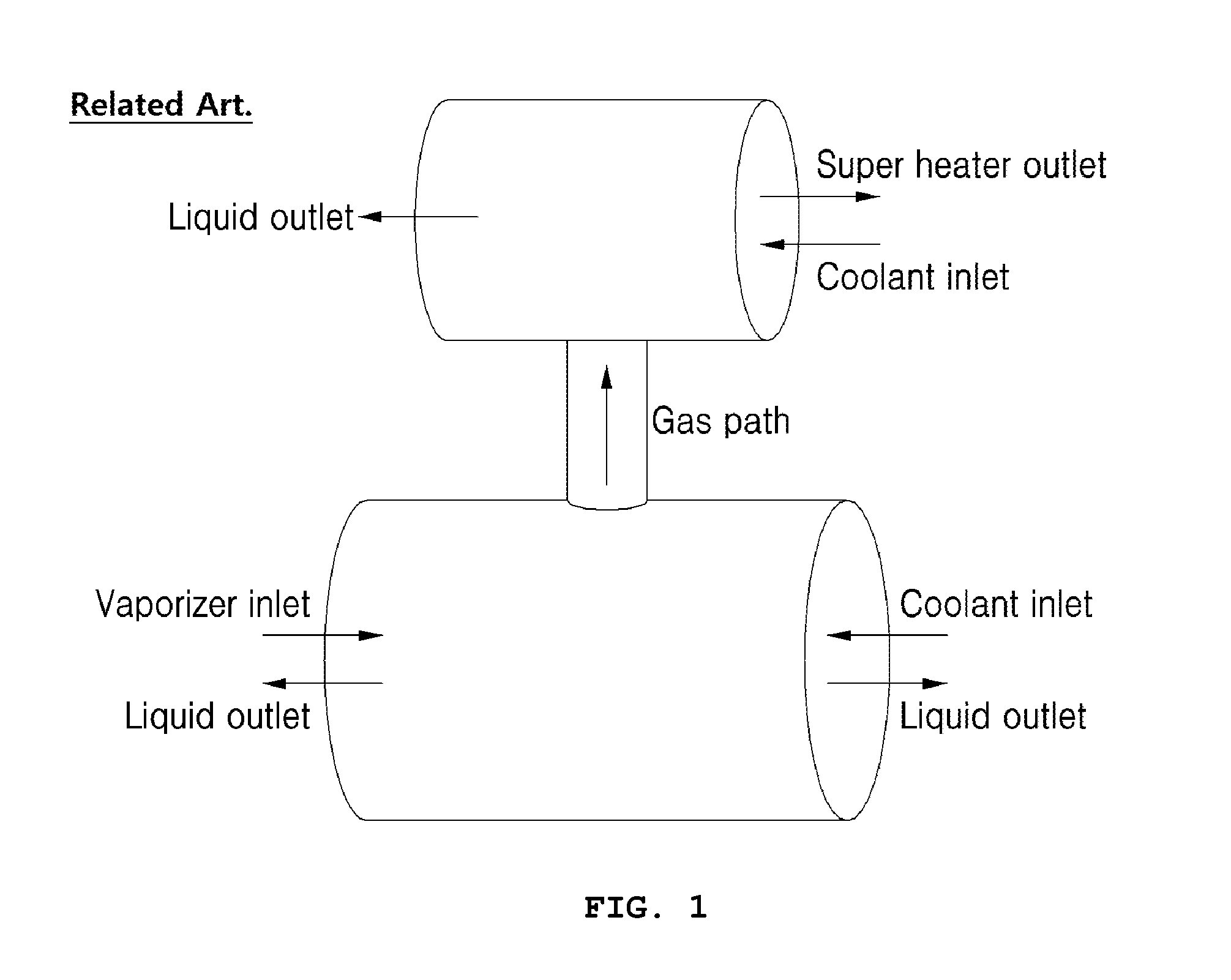
[0006] The shell-tube type heat exchanger is also used to separate an injected fluid into liquid and gas with application of heat, as illustrated in FIG. 1.
[0007] In the case where the fluid is separated into liquid and gas by the conventional shell-tube type heat exchanger, the separation is easy since the volume of the heat exchanger itself is very large. However, the shell-tube type heat exchanger has a problem in that it is difficult for the heat exchanger to be used in a space restricted environment due to the large volume of the heat exchanger.
[0008] To solve these problems, as illustrated in FIG. 2, a printed circuit-type heat exchanger capable of being designed in a small volume may be used.
[0009] However, when the gas-liquid separation is obtained by using the printed circuit-type heat exchanger, it is required to separately fabricate a vaporizer, a super heater, and a gas-liquid separator, problematically causing tube connection to become very complicated.
[0010] Thus, it is required to provide a technique for a printed circuit-type heat exchanger to solve the above-mentioned problems with the related art.
SUMMARY OF THE INVENTION
[0011] Accordingly, it is an object of the present invention to provide a printed circuit-type heat exchanger capable of performing a gas-liquid function as well.
[0012] It is a further object of the present invention to provide a printed circuit-type heat exchanger and a gas-liquid separating device having a gas-liquid separating structure in which a vaporized gas of the fluid B transferred from the vaporizer is effectively separated and in which the vaporized gas is stably transferred to the super heater, and thus considerably improves the gas-liquid separating efficiency.
[0013] According to one aspect of the present invention, there is provided a printed circuit-type heat exchanger in which an A-fluid channel and a B-fluid channel are formed to exchange heat between a fluid A and a fluid B. The heat exchanger may include a vaporizer having a structure in which one or more A-channel plates and one or more B-channel plates are sequentially stacked, the A-channel plates of the vaporizer each having an A-fluid channel and the B-channel plates of the vaporizer each having an B-fluid channel intersecting with the A-fluid channel of the vaporizer, the vaporizer configured to vaporize the fluid A with heat exchange through the A-fluid channels and to pass the vaporized fluid A; a gas-liquid separator provided next to the vaporizer to separate the fluid A transferred from the vaporizer into a vaporized gas and a non-vaporized liquid, the gas-liquid separator including a gas outlet formed on one side through which the vaporized gas of the fluid A is passed and a liquid outlet formed on the other side through which the non-vaporized liquid of the fluid A is discharged; and a super heater provided next to the gas-liquid separator having a structure in which one or more A-channel plates and one or more B-channel plates are sequentially stacked, the A-channel plates of the super heater each having an A-fluid channel and the B-channel plates of the super heater each having a B-fluid channel intersecting with the A-fluid channel of the super heater, the super heater configured to super heat the vaporized gas transferred from the gas-liquid separator with heat exchange through the A-fluid channels, and including a gas outlet formed on one side through which the superheated gas is discharged.
[0014] The heat exchanger may further include one or both of a first intermediate plate disposed between the vaporizer and the gas-liquid separator to separate the vaporizer from the gas-liquid separator, the first intermediate plate including a fluid connection path so that an A-fluid outlet of the vaporizer communicates with the gas-liquid separator; and a second intermediate plate disposed between the gas-liquid separator and the super heater to separate the super heater from the gas-liquid separator, the second intermediate plate including a fluid connection path so that an inlet of the super heater for the vaporized fluid A communicates with the gas-liquid separator.
[0015] The gas-liquid separator may have a sufficient width to separate the vaporizer and the super heater by a predetermined distance, and may include an internal space to perform a gas-liquid separating function. Here, the heat exchanger may further include a baffle configured to separate a gas and which may be disposed on an upper end of the internal space of the gas-liquid separator and is preferably disposed adjacent to the gas outlet of the gas-liquid separator.
[0016] The vaporizer may be detachably attached to one side of the gas-liquid separator, and the super heater may be detachably attached to the other side of the gas-liquid separator.
[0017] The A-fluid channel of each A-channel plate may include a series of bends in alternating directions. The bends may form a continuous path following a zigzag pattern, and the channel may have a horizontally symmetrical structure in which sides of consecutive bends contact each other.
[0018] According to another aspect of the present invention, there is provided a gas-liquid separating device including the above vaporizer, the above gas-liquid separator, and the above super heater.
[0019] The effects, features, and advantages of the invention are not limited to the above effects, features, and advantages, and other effects, features, and advantages of the invention will be understood from a detailed description of the invention or the configurations recited in the accompanying claims.
BRIEF DESCRIPTION OF THE DRAWINGS
[0020] The above and other objects, features and other advantages of the present disclosure will be more clearly understood from the following detailed description taken in conjunction with the accompanying drawings, in which:
[0021] FIG. 1 is a schematic diagram of a conventional shell-tube type heat exchanger performing gas-liquid separation;
[0022] FIG. 2 is a schematic diagram of a conventional printed circuit-type heat exchanger performing gas-liquid separation;
[0023] FIG. 3 is a diagrammatic view of a printed circuit-type heat exchanger according to an embodiment of the present invention;
[0024] FIG. 4 is an exploded perspective view of the printed circuit-type heat exchanger according to the embodiment of the present invention;
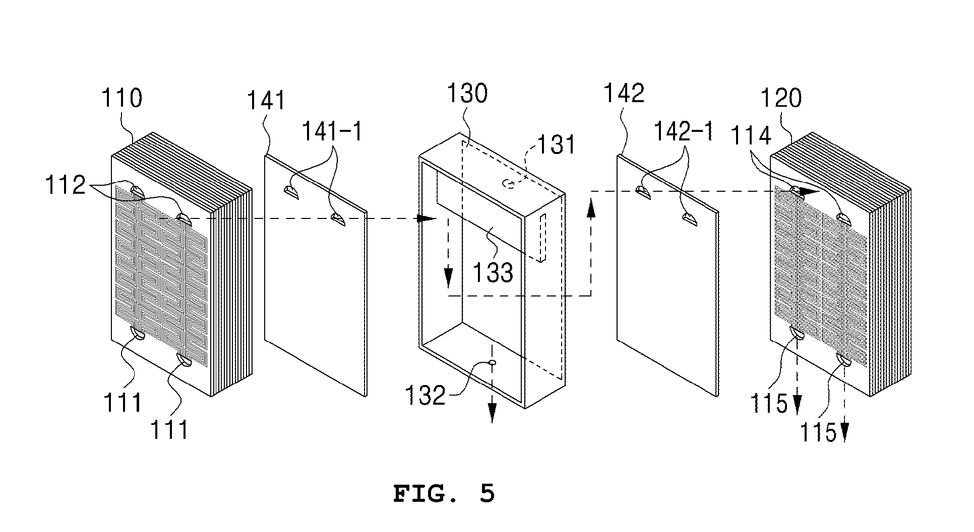
[0025] FIG. 5 is a perspective view of a portion of FIG. 4, showing the vaporizer, the gas-liquid separator, and the super heater; and
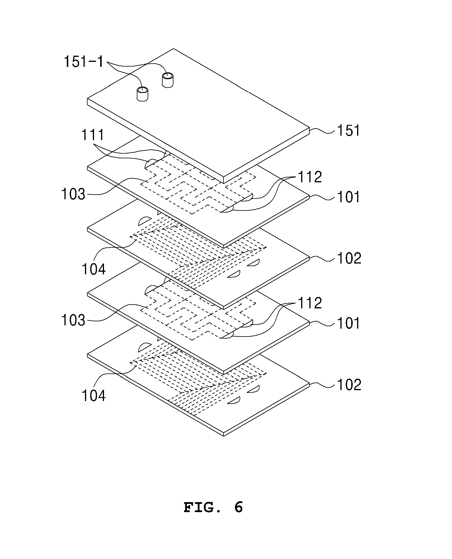
[0026] FIG. 6 is an exploded perspective view of the vaporizer shown in FIGS. 4 and 5.
DETAILED DESCRIPTION OF THE INVENTION
[0027] Hereinafter, exemplary embodiments of the present invention will be described in detail with reference to the accompanying drawings. It should be noted that terms used in this specification and claims should not be limited to a common meaning or a dictionary definition, but should be construed as the meanings and concepts according to technical spirits of the present invention.
[0028] It will be understood that when an element is referred to as being "on" another element, it can be directly on the other element or intervening elements may be present therebetween. Further, it will be understood that the term "comprising" or "including" specifies the presence of stated elements, but does not preclude the presence or addition of one or more other elements, unless the context clearly indicates otherwise.
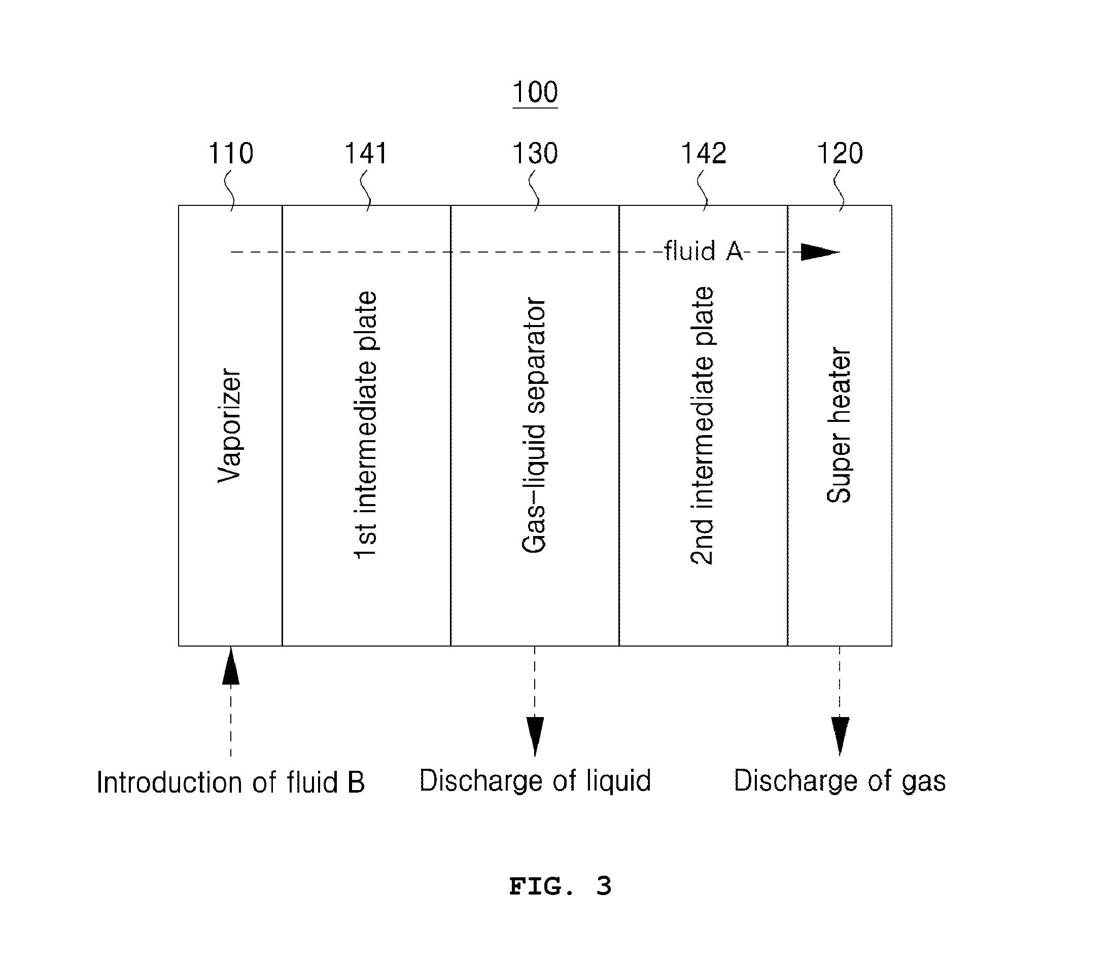
[0029] Referring to FIGS. 3-5, a printed circuit-type heat exchanger 100 has a structure in which a channel for fluid A and a channel for fluid B are formed so as to perform a heat exchange between fluid A and fluid B. The printed circuit-type heat exchanger 100 includes a vaporizer 110, a gas-liquid separator 130, and a supper heater 120 so as to perform a gas-liquid separation function in addition to the heat exchange. While these drawings focus on the printed circuit-type heat exchanger, the present invention may further provide a gas-liquid separating device including the vaporizer 110, the gas-liquid separator 130, and the super heater 120.
[0030] Hereinafter, the vaporizer 110, the gas-liquid separator 130, and the super heater 120 constituting both the printed circuit-type heat exchanger and the gas-liquid separating device will be described in detail with reference to the accompanying drawings, in which FIG. 6 illustrates the vaporizer 110 shown in FIGS. 4 and 5.
[0031] The printed circuit-type heat exchanger 100 has a compact structure in which the vaporizer 110, the gas-liquid separator 130, and the super heater 120 are integrally formed so that the structure can be properly applied to a narrow space environment.
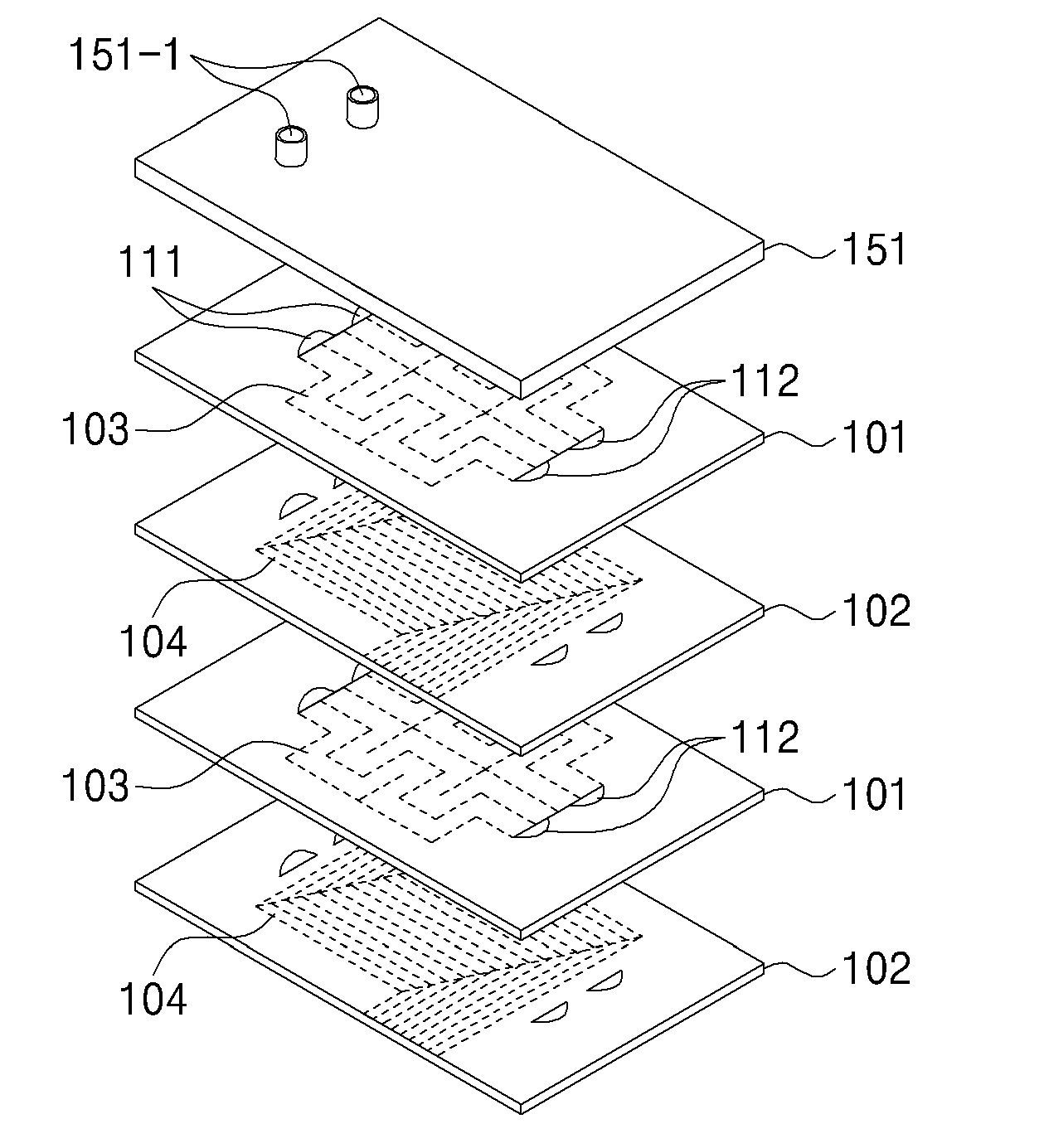
[0032] Referring to FIG. 6, the vaporizer 110 has a structure in which one or more A-channel plates 101 and one or more B-channel plates 102 are sequentially stacked so as to perform their respective functions using a heat exchange of introduced fluid. Although not specifically shown, the super heater 120 has a corresponding structure in which one or more A-channel plates 101 and one or more B-channel plates 102 are sequentially stacked so as to perform their respective functions using a heat exchange of introduced fluid.
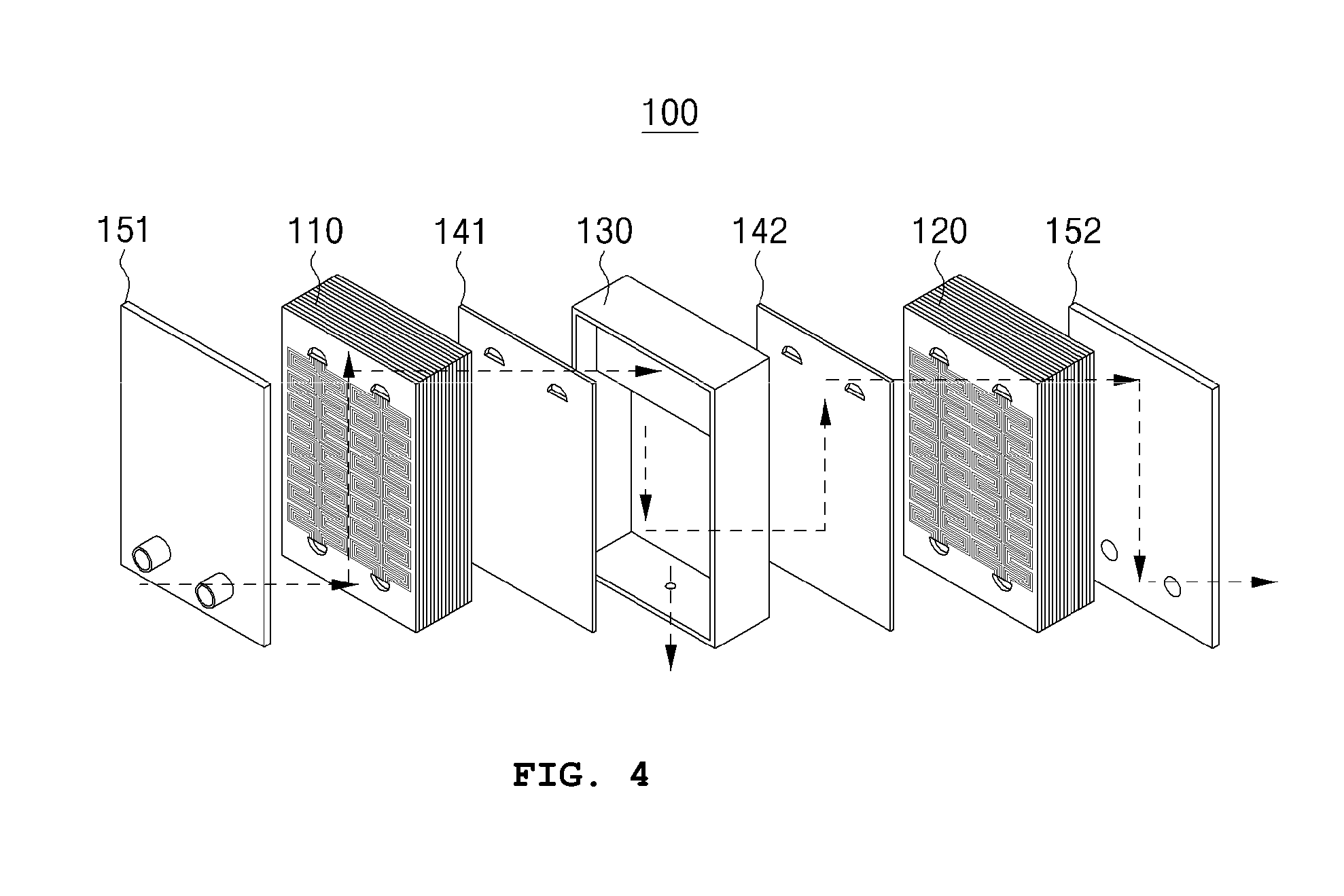
[0033] Further, as illustrated in FIG. 4, first and second cover sections 151 and 152 may be respectively attached to both sides of a coupled unit of the vaporizer 110, the gas-liquid separator 130, and the super heater 120. Here, the first cover section 151 is a planar structure which closes one side of the vaporizer 110 and has an A-fluid inlet 151-1 through which a fluid A is introduced into an A-fluid channel 103 of the vaporizer 110. Further, the second cover section 152 is a planar structure which closes one side of the super heater 120 and has an outlet 152-1 through which a gas superheated from the super heater 120 is discharged to the outside.
[0034] The A-fluid channel 103 formed in the A-channel plate 101 has a horizontally symmetrical structure in a plan view (i.e., a vertical line of symmetry), which structure preferably has a sufficiently wide contact area to maximize heat exchange efficiency. Specifically, with respect to a plan view of the A-fluid channel 103, the channel has a structure having a series of bends in alternating (e.g., opposite) directions which form a continuous path following a zigzag pattern. Here, the channel has the horizontally symmetrical structure in which sides of consecutive bends contact each other, thereby maximizing a contact area with a fluid and improving heat exchange efficiency.
[0035] The vaporizer 110 has a structure which vaporizes a fluid A passed through the A-fluid channel 103 with heat exchange and moves the vaporized fluid to the gas-liquid separator 130. That is, the vaporized gas of the fluid A is passed to a next stage unit. The super heater 120 has the same structure as the vaporizer 110, although respective structures for introducing fluid and for discharging fluid may have different physical properties.
[0036] The gas-liquid separator 130 between the vaporizer 110 and the super heater 120 may transfer a vaporized gas of the fluid A transferred from the vaporizer 110 to the super heater 120, i.e., a next stage unit. At the same time, the gas-liquid separator 130 may discharge a non-vaporized liquid of the fluid A transferred from the vaporizer 110 to the outside.
[0037] Specifically, the gas-liquid separator 130 has a structure in which a gas outlet 131 formed on one side is provided to pass the vaporized gas of the fluid A from the vaporizer 110 to the super heater 120 and in which a liquid outlet 132 formed on the other side is provided to discharge the non-vaporized liquid of the fluid A from the vaporizer 110 to the outside.
[0038] The gas-liquid separator 130 has a sufficient width to separate the vaporizer 110 and the super heater 120 by a predetermined distance, and includes an internal space to perform a gas-liquid separating function. As shown in FIG. 5, a baffle 133 for separating a gas is provided on the upper end of an internal space of the gas-liquid separator 130, so as to considerably improve the gas-liquid separating efficiency. Here, the baffle 133 is preferably provided adjacent to the gas outlet 131.
[0039] If needed, a first intermediate plate 141 may be provided between the vaporizer 110 and the gas-liquid separator 130, as shown in FIGS. 4 and 5.
[0040] The first intermediate plate 141 may separate the vaporizer 110 from the gas-liquid separator 130. Further, in an embodiment, a fluid connection path 141-1 may be formed at one end of the first intermediate plate 141 so that the A-fluid outlet 112 communicates with the gas-liquid separator 130.
[0041] Further, a second intermediate plate 142 may be provided between the gas-liquid separator 130 and super heater 120. Here, the second intermediate plate 142 may separate the super heater 120 from the gas-liquid separator 130, and a fluid connection path 142-1 may be formed at one end of the second intermediate plate 142 so that an inlet 114 for vaporized fluid A communicates with the gas-liquid separator 130.
[0042] In the meantime, as shown in FIG. 5, the vaporizer 110 and the super heater 120 may be detachably attached to both sides of the gas-liquid separator 130, respectively. In this case, if the vaporizer 110 or the super heater 120 requires maintenance, the vaporizer or the super heater can be easily removed from the gas-liquid separator 130, providing easy access.
[0043] As set forth in the foregoing description, the present invention provides the printed circuit-type heat exchanger including a characterized structure having the vaporizer, the gas-liquid separator, and the super heater, capable of performing a gas-liquid separating function as well.
[0044] Further, according to the present invention, a characterized structure of the first and second intermediate plates and the gas-liquid separator is provided, thereby effectively separating a vaporized gas of the fluid B transferred from the vaporizer and stably transferring the vaporized gas to the super heater, and thus considerably improving the gas-liquid separating efficiency.
[0045] Furthermore, according to the present invention, a characterized structure of the gas-liquid separator has the baffle and the gas outlet, thereby effectively separating a vaporized gas of the fluid B transferred from the vaporizer and stably transferring the vaporized gas to the super heater, and thus considerably improves the gas-liquid separating efficiency.
[0046] While the exemplary embodiments of the present invention have been described in the detailed description, the present invention is not limited thereto, but should be construed as including all of modifications, equivalents, and substitutions falling within the spirit and scope of the invention defined by the appended claims.
[0047] That is, the present invention is not limited to the above-mentioned embodiments and the description thereof, and it will be appreciated by those skilled in the art that various modifications and equivalent embodiments are possible without departing from the scope and spirit of the invention defined by the appended claims and that the present invention covers all the modifications and equivalents falling within the spirit and the scope of the present invention as defined by the appended claims.
* * * * *
D00000
D00001
D00002
D00003
D00004
D00005
D00006
XML
uspto.report is an independent third-party trademark research tool that is not affiliated, endorsed, or sponsored by the United States Patent and Trademark Office (USPTO) or any other governmental organization. The information provided by uspto.report is based on publicly available data at the time of writing and is intended for informational purposes only.
While we strive to provide accurate and up-to-date information, we do not guarantee the accuracy, completeness, reliability, or suitability of the information displayed on this site. The use of this site is at your own risk. Any reliance you place on such information is therefore strictly at your own risk.
All official trademark data, including owner information, should be verified by visiting the official USPTO website at www.uspto.gov. This site is not intended to replace professional legal advice and should not be used as a substitute for consulting with a legal professional who is knowledgeable about trademark law.