Collimated Effect Luminaire
JURIK; Pavel ; et al.
U.S. patent application number 15/125161 was filed with the patent office on 2019-06-27 for collimated effect luminaire. This patent application is currently assigned to Robe Lighting s.r.o.. The applicant listed for this patent is ROBE LIGHTING, INC.. Invention is credited to Pavel JURIK, Josef VALCHAR.
| Application Number | 20190195471 15/125161 |
| Document ID | / |
| Family ID | 53433250 |
| Filed Date | 2019-06-27 |


| United States Patent Application | 20190195471 |
| Kind Code | A1 |
| JURIK; Pavel ; et al. | June 27, 2019 |
COLLIMATED EFFECT LUMINAIRE
Abstract
This specification describes an improved automated luminaire employing an improved laser optical module with a laser module and an optical module, which expands the width of the laser light beam emitted from the laser module.
| Inventors: | JURIK; Pavel; (Prostredni Becva, CZ) ; VALCHAR; Josef; (Prostredni Becva, TX) | ||||||||||
| Applicant: |
|
||||||||||
|---|---|---|---|---|---|---|---|---|---|---|---|
| Assignee: | Robe Lighting s.r.o. Roznov pod Radhostem CZ |
||||||||||
| Family ID: | 53433250 | ||||||||||
| Appl. No.: | 15/125161 | ||||||||||
| Filed: | March 10, 2015 | ||||||||||
| PCT Filed: | March 10, 2015 | ||||||||||
| PCT NO: | PCT/US15/19741 | ||||||||||
| 371 Date: | September 10, 2016 |
Related U.S. Patent Documents
| Application Number | Filing Date | Patent Number | ||
|---|---|---|---|---|
| 61950387 | Mar 10, 2014 | |||
| Current U.S. Class: | 1/1 |
| Current CPC Class: | G02B 19/0028 20130101; F21V 5/003 20130101; F21W 2131/406 20130101; G02B 19/0052 20130101; F21W 2131/40 20130101; F21V 14/06 20130101; F21V 5/008 20130101; F21Y 2115/10 20160801; F21Y 2113/10 20160801 |
| International Class: | F21V 14/06 20060101 F21V014/06; F21V 5/00 20060101 F21V005/00 |
Claims
1. An automated luminaire comprising: a laser module generating a directed laser light beam; an optical module for widening the effective diameter of the laser light beam. a beam positioner which changes the direction of the light beam.
2. The automated luminaire of claim 1 where the laser module can generate laser light beams of more than one primary color or a variety of colors based on combinations of the primary colors.
3. An automated luminaire of claim 2 where the primary colors are: red and green, or red and blue, or green and blue, or red, green and blue or include violet.
4. The automated luminaire of claim 1 where the beam positioner is a gantry mounted mirror which reflects the light beam in changeable directions based on the changeable position of the mirror.
5. An automated luminaire of claim 1 where the beam positioner is a pan and tilt gantry into which the laser module and optical module form a laser optical module which is mounted in the pan and tilt gantry.
6. An automated luminaire comprising where the laser module and optical module form a laser optical module and the luminaire comprises a plurality of these laser optical modules.
8. An automated luminaire where the optical module is comprised of a negative lens followed by a positive lens.
9. An automated luminaire of claim 1 where to optical module includes articulable elements that vary the beam widening effect of the optical module.
10. An automated luminaire of claim 1 where the optical module employs a holographic lens
11. An automated luminaire of claim 1 where the optical module employs a gradient for splitting the light beam into a pattern of individual laser beams.
Description
RELATED APPLICATION
[0001] This application claims priority of U.S. Provisional Application No. 61/950,387 filed on 10 Mar. 2014. and PCT Application PCT/US15/19741 filed 10 Mar. 2015.
TECHNICAL FIELD OF THE INVENTION
[0002] The present invention generally relates to a method for controlling the light output from a laser when used in a light beam producing luminaire, specifically to a method relating to producing a wide, parallel beam and for controlling the size of that beam.
BACKGROUND OF THE INVENTION
[0003] It is well known to use lasers in luminaire designed for entertainment use in theatres, television studios, concerts, theme parks, night clubs and other venues. These lasers are also being utilized in systems with automated and remotely controllable functionality. However, a concern with all laser systems is the safety of the light emitted. Any high-powered system cannot be allowed to directly impinge on the eye of a viewer, as it will damage the lens or retina. Further, the major feature of a laser beam is that it is narrow, and parallel (collimated). In some circumstances however, it would be advantageous if the light beam could remain collimated but be much wider. A wider beam has the advantage that it is more visible as a solid bar in the air, particularly if fog or haze is used, and that a wide beam will have a much lower power density and will consequently be much less dangerous.
[0004] For color control it is common to use an array of lasers of different colors. For example a common configuration is to use a mix of Red, Green and Blue lasers. This configuration allows the user to create the color they desire by mixing appropriate levels of the three colors. For example illuminating the Red and Green lasers while leaving the Blue extinguished will result in an output that appears Yellow. Similarly Red and Blue will result in Magenta, and Blue and Green will result in Cyan. By judicious control of these three controls the user may achieve any color they desire. More than three colors may also be used and it is possible to add an Amber or White laser to the Red, Green and Blue to enhance the color mixing and improve the gamut of colors available.
[0005] There is a need for a beam control system for a laser based luminaire that provides improvements in beam collimation, beam size adjustment, and safety.
BRIEF DESCRIPTION OF THE DRAWINGS
[0006] For a more complete understanding of the present invention and the advantages thereof, reference is now made to the following description taken in conjunction with the accompanying drawings in which like reference numerals indicate like features and wherein:
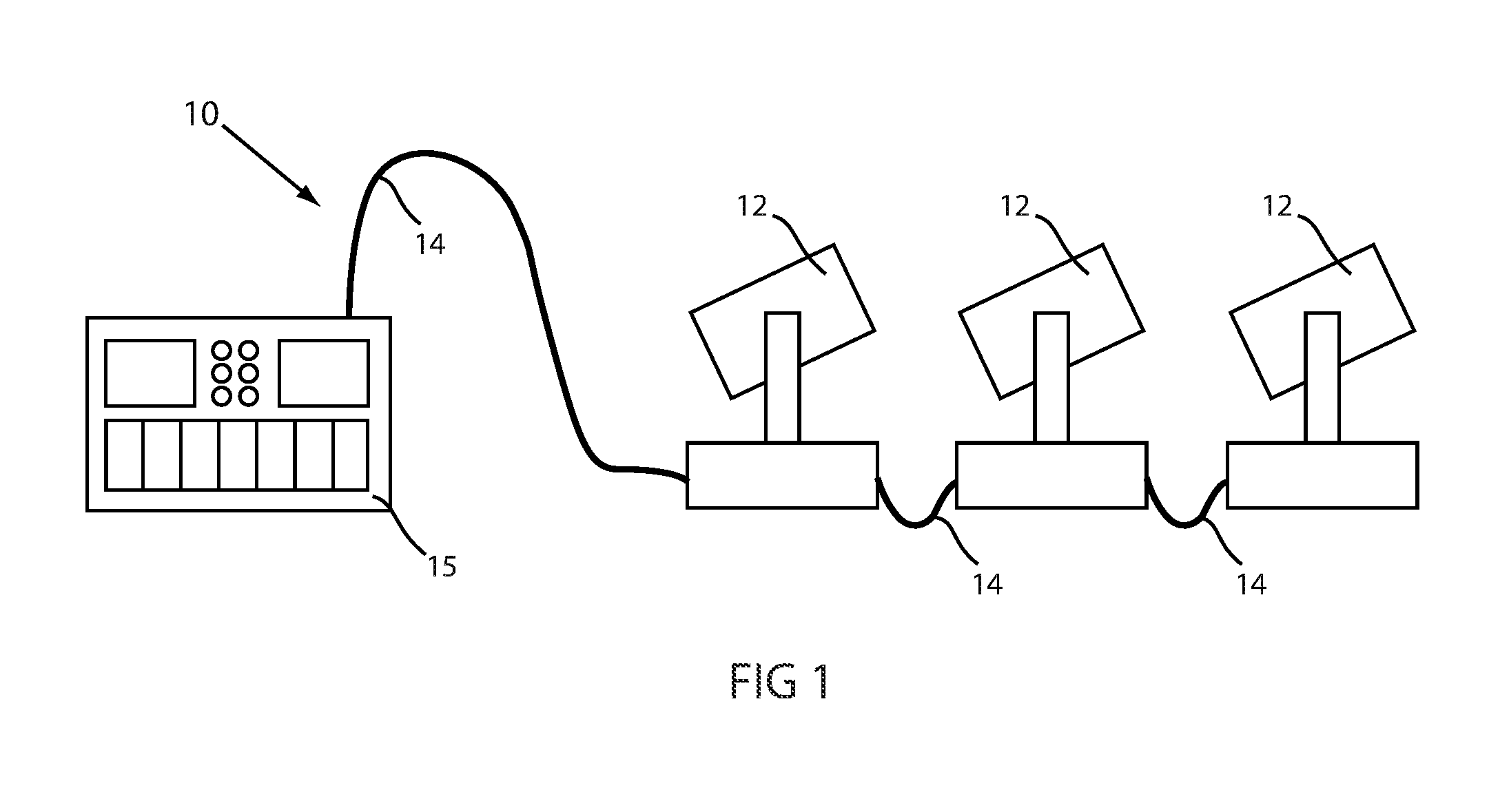
[0007] FIG. 1 illustrates a typical automated lighting system;
[0008] FIG. 2 illustrates an embodiment of an improved laser module optical design for automated luminaire;
[0009] FIG. 3 illustrates a further embodiment of the improved laser module optical design for automated luminaire;
[0010] FIG. 4 illustrates a further embodiment of the improved laser module optical design for an automated luminaire;
[0011] FIG. 5 illustrates an automated luminaire fitted with an array of laser modules; and;
[0012] FIG. 6 illustrates an automated luminaire fitted with a large laser module.
DETAILED DESCRIPTION OF THE INVENTION
[0013] Preferred embodiments of the present invention are illustrated in the FIGURES, like numerals being used to refer to like and corresponding parts of the various drawings.
[0014] The present invention generally relates to a method for controlling the light output from a laser when used in a light beam producing luminaire, specifically to a method relating to producing a wide, parallel beam and for controlling the size of that beam.
[0015] FIG. 1 illustrates a typical multiparameter automated LED luminaire system 10. These systems commonly include a plurality of multiparameter automated luminaires 12 which typically each contain on-board an array of LEDs, and electric motors coupled to mechanical drives systems and control electronics (not shown). In addition to being connected to mains power either directly or through a power distribution system (not shown), each luminaire is connected is series or in parallel to data link 14 to one or more control desk(s) 15. The automated luminaire system 10 is typically controlled by an operator through the control desk 15. Consequently, to affect this control, both the control desk 10 and the individual luminaires typically include electronic circuitry as part of the electromechanical control system for controlling the automated lighting parameters.
[0016] FIG. 2 illustrates an embodiment of the optical design of the invention, as fitted to an automated luminaire. Laser optical module 25 including Laser module 20, which emits a narrow collimated beam along optical axis 21 towards lenses 22, and 24. Lenses 22 and 24 act as a beam expanding system such that the output beam from the optical system remains parallel and collimated, but is significantly increased in diameter. The large parallel exit beam has a lower power density than the narrow input beam and is thus much safer for the audience. The system illustrated in FIG. 2 utilizes a negative lens, 22, and a positive lens, 24. However other optical systems using any number of lenses are possible without detracting from the intent of the invention. In particular, it is known to produce an alternative beam expanding optical system using two positive lenses. It is also possible to use holographic lenses or reflective systems to achieve beam expansion.
[0017] Laser module 20 may contain a single laser of a single color, or may contain an array of lasers in multiple colors, for example, red, green, and blue/violet lasers.
[0018] FIGS. 3 and 4 illustrate a further embodiment of the optical design of the invention, as fitted to an automated luminaire. Laser module 20 emits a narrow collimated beam along optical axis 21 towards lenses 22, 24, and 26. Lenses 22, 24, and 26 act as a beam expanding system such that the output beam from the optical system remains parallel and collimated, but is significantly increased in diameter. The large parallel exit beam has a lower power density than the narrow input beam and is thus much safer for the audience. In this embodiment one or more of lenses 22, 24, and 26 may be moved along the optical axis 21. This movement allows adjustment of the beam expansion of the optical system. In FIG. 3 lenses 22, 24, and 26 are adjusted such that the output beam is narrow (although still wider than the input beam) while in FIG. 4 lenses 22, 24, and 26 are adjusted such that the output beam is wide. The system illustrated in FIGS. 3 and 4 utilizes a negative lens, 22, and two positive lenses, 24, and 26. However other optical systems using any number of lenses are possible without detracting from the intent of the invention. It is also possible to use holographic lenses or reflective systems or a gradient beam splitter to achieve beam expansion
[0019] The movement of one or more lenses 22, 24, and 26 along the optical axis and thus the amount of beam expansion may be achieved using stepper motors, linear actuators, servo motors, or other mechanisms as well known in the art.
[0020] Laser module 20 may contain a single laser of a single color, or may contain an array of lasers in multiple colors, for example, red, green, and blue lasers.
[0021] FIG. 5 illustrates an automated luminaire fitted with a plurality of laser modules. Automated luminaire 30 comprises a base, 35, rotatably connected to a yoke assembly, 33, which in turn is rotatably connected to a head 32. The rotation of yoke 33 relative to the base 35 is often referred to as pan, and rotation of the head 32 relative to yoke 33 is often known as tilt. By combined and coordinated control of pan and tilt motions the head 32 may be pointed in any desired direction relative to fixed base 35.
[0022] Head 32 is fitted with a plurality of light emitting modules 34 each of which comprises a laser module and optical system as illustrated in FIGS. 2, 3, and 4. In this embodiment each of the light emitting modules 34 may be controllable independently for color and beam expansion.
[0023] FIG. 6 illustrates an alternative automated luminaire fitted with a single laser module. Automated luminaire 40 comprises a base, 45, rotatably connected to a yoke assembly, 43, which in turn is rotatably connected to a head 42. The rotation of yoke 43 relative to the base 45 is often referred to as pan, and rotation of the head 42 relative to yoke 43 is often known as tilt. By combined and coordinated control of pan and tilt motions the head 42 may be pointed in any desired direction relative to fixed base 45.
[0024] Head 42 is fitted with a light emitting module 44, which comprises a laser module and optical system as illustrated in FIGS. 2, 3, and 4 of this document. In this embodiment the laser module 44 may be larger and more powerful than those 34 illustrated in FIG. 5. Light emitting module 44 may be controllable for color and beam expansion.
[0025] While the disclosure has been described with respect to a limited number of embodiments, those skilled in the art, having benefit of this disclosure, will appreciate that other embodiments may be devised which do not depart from the scope of the disclosure as disclosed herein. The disclosure has been described in detail, it should be understood that various changes, substitutions and alterations can be made hereto without departing from the spirit and scope of the disclosure.
* * * * *
D00000
D00001
D00002
D00003
D00004
D00005
XML
uspto.report is an independent third-party trademark research tool that is not affiliated, endorsed, or sponsored by the United States Patent and Trademark Office (USPTO) or any other governmental organization. The information provided by uspto.report is based on publicly available data at the time of writing and is intended for informational purposes only.
While we strive to provide accurate and up-to-date information, we do not guarantee the accuracy, completeness, reliability, or suitability of the information displayed on this site. The use of this site is at your own risk. Any reliance you place on such information is therefore strictly at your own risk.
All official trademark data, including owner information, should be verified by visiting the official USPTO website at www.uspto.gov. This site is not intended to replace professional legal advice and should not be used as a substitute for consulting with a legal professional who is knowledgeable about trademark law.