Optical System For A Led Luminaire
JURIK; Pavel ; et al.
U.S. patent application number 15/078805 was filed with the patent office on 2019-06-27 for optical system for a led luminaire. The applicant listed for this patent is Robe Lighting s.r.o.. Invention is credited to Pavel JURIK, Josef VALCHAR.
| Application Number | 20190195446 15/078805 |
| Document ID | / |
| Family ID | 58257147 |
| Filed Date | 2019-06-27 |


| United States Patent Application | 20190195446 |
| Kind Code | A9 |
| JURIK; Pavel ; et al. | June 27, 2019 |
OPTICAL SYSTEM FOR A LED LUMINAIRE
Abstract
Single multidie LED light homogenizer source for an automated multiparmeter luminaire.
| Inventors: | JURIK; Pavel; (Prostredni Becva, CZ) ; VALCHAR; Josef; (Prostredni Becva, CZ) | ||||||||||
| Applicant: |
|
||||||||||
|---|---|---|---|---|---|---|---|---|---|---|---|
| Prior Publication: |
|
||||||||||
| Family ID: | 58257147 | ||||||||||
| Appl. No.: | 15/078805 | ||||||||||
| Filed: | March 23, 2016 |
Related U.S. Patent Documents
| Application Number | Filing Date | Patent Number | ||
|---|---|---|---|---|
| 14682834 | Apr 9, 2015 | |||
| 15078805 | ||||
| 15024008 | Mar 22, 2016 | |||
| PCT/US15/19748 | Mar 10, 2015 | |||
| 14682834 | ||||
| 61950403 | Mar 10, 2014 | |||
| Current U.S. Class: | 1/1 |
| Current CPC Class: | F21V 19/02 20130101; F21Y 2113/13 20160801; F21V 5/008 20130101; F21Y 2115/10 20160801; F21W 2131/406 20130101; F21V 7/041 20130101; F21V 13/04 20130101; F21V 7/043 20130101; F21V 14/06 20130101; G02B 19/0066 20130101; F21S 10/007 20130101; F21V 5/02 20130101; F21V 21/30 20130101; G02B 26/023 20130101; G02B 19/00 20130101; G02B 27/0994 20130101; F21V 7/0091 20130101 |
| International Class: | F21S 10/00 20060101 F21S010/00; F21V 7/00 20060101 F21V007/00; F21V 19/02 20060101 F21V019/02; F21V 5/02 20060101 F21V005/02; F21V 13/04 20060101 F21V013/04 |
Claims
1. An automated mulitparameter luminaire with a light engine comprising: a single multiple LED light source mounted in a collimator directing light to an elongated TIR homogenizer a light condenser transforming the homogenized beam from the homogenizer into a focused light beam gobo and prism, or gobo, or prism light modulators; and a zoom lens system to alter the focus or beam angle or zoom of the light beam.
Description
RELATED APPLICATION(S)
[0001] This utility application claims priority of and through the following: [0002] U.S. Utility application Ser. No. 15/024,129 filed 23 Mar. 2016, [0003] PCT Application PCT/US15/19748 filed 10 Mar. 2015, and [0004] U.S. Provisional Application 61/950,403 filed 10 Mar. 2014; and [0005] U.S. Utility application Ser. No. 14/682,834 filed 9 Apr. 2015, and [0006] U.S. Provisional 62/133,956 filed 16 Mar. 2015
TECHNICAL FIELD OF THE INVENTION
[0007] The present invention generally relates to an automated luminaire, specifically to an optical system in an automated LED luminaire.
BACKGROUND OF THE INVENTION
[0008] Luminaires with automated and remotely controllable functionality are well known in the entertainment and architectural lighting markets. Such products are commonly used in theatres, television studios, concerts, theme parks, night clubs and other venues. A typical product will commonly provide control over the pan and tilt functions of the luminaire allowing the operator to control the direction the luminaire is pointing and thus the position of the light beam on the stage or in the studio. Typically this position control is done via control of the luminaire's position in two orthogonal rotational axes usually referred to as pan and tilt. Many products provide control over other parameters such as the intensity, color, focus, beam size, beam shape and beam pattern. The beam pattern is often provided by a stencil or slide called a gobo which may be a steel, aluminum or etched glass pattern. The products manufactured by Robe Show Lighting such as the Robin MMX Spot are typical of the art.
[0009] The optical systems of such automated luminaires may be designed such that a very narrow output beam is produced so that the units may be used with long throws or for almost parallel light laser like effects. These optics are often called `Beam` optics. To form this narrow beam with the large light sources in the prior art the output lens either needed to be very large with a large separation between the lens and the gobos or of a short focal length and much closer to the gobos
[0010] FIG. 1 illustrates a multiparameter automated luminaire system 10. These systems commonly include a plurality of multiparameter automated luminaires 12 which typically each contain on-board a light source (not shown), light modulation devices, electric motors coupled to mechanical drives systems and control electronics (not shown). In addition to being connected to mains power either directly or through a power distribution system (not shown), each luminaire is connected is series or in parallel to data link 14 to one or more control desks 15. The luminaire system 10 is typically controlled by an operator through the control desk 15. Control of the automated luminaire 12 is effectuated by electromechanical devices within the luminaire 12 and electronic circuitry including firmware and software within the control desk 15 and/or the luminaire 12. In many of the figures herein, important parts like electromechanical components such as motors and electronic circuitry including software and firmware and some hardware are not shown in order to simplify the drawings so as to teach how to practice the inventions taught herein. Persons of skill in the art will recognize the need for these parts and should be able to readily fill in these parts.
[0011] In prior art luminaires lamps with extremely small light sources have been developed. These often use a very short arc gap, of the order of 1 mm, between two electrodes as the light producing means. These lamps may be used for producing a very narrow beam as their source etendue is low, and the size of the lenses and optical systems to collimate the light from such a small source can be substantially reduced. However, the short arc and small light source coupled with the short focal length, and thus large light beam angles, of the reflector also tend to produce substantial amounts of unwanted and objectionable spill light which can escape between gobos or around the dimming shutters. Further, arc lamps require very high voltages in order to ignite the lamp, and can produce dangerous amounts of heat and UV energy, which needs to be filtered out. In recent times LED emitters have become available that are small enough and powerful enough to be used in this kind of luminaire. However, they need improvements to their design to improve the homogenizing and collimation of their optical systems.
[0012] There is an increased need for an improved automated luminaire utilizing an LED light source capable of producing both very narrow output beams and of projecting images.
BRIEF DESCRIPTION OF THE DRAWINGS
[0013] For a more complete understanding of the present invention and the advantages thereof, reference is now made to the following description taken in conjunction with the accompanying drawings in which like reference numerals indicate like features and wherein:
[0014] FIG. 1 illustrates a typical automated lighting system;
[0015] FIG. 2a illustrates an embodiment of an improved light module for an automated luminaire;
[0016] FIG. 2b illustrates an alternative embodiment of an improved light module for an automated luminaire;
[0017] FIG. 3 illustrates an embodiment of the light engine optical system employing an improved LED light module with narrow beam angle;
[0018] FIG. 4 illustrates an isometric view of an embodiment illustrated in FIG. 3; and;
[0019] FIG. 5 illustrates an isometric view of the gimbaled housing for the light engine illustrated in FIG. 4.
[0020] FIG. 6 illustrates an alternative embodiment of portions of the light source side of the light engine;
[0021] FIG. 7 illustrates the alternative embodiment portions of the light engine illustrated in FIG. 6 in a different configuration;
[0022] FIG. 8 illustrates a further alternative embodiment of the portions of the light engine illustrated in FIG. 5 & FIG. 6 with the addition of a image multiplier;
[0023] FIG. 9 illustrates a different configuration of the further alternative embodiment of the portions of the light engine illustrated in FIG. 8, and;
[0024] FIG. 10 illustrates in more detail the articulation of the image multiplier in the further alternative embodiment of FIG. 8 and FIG. 9;
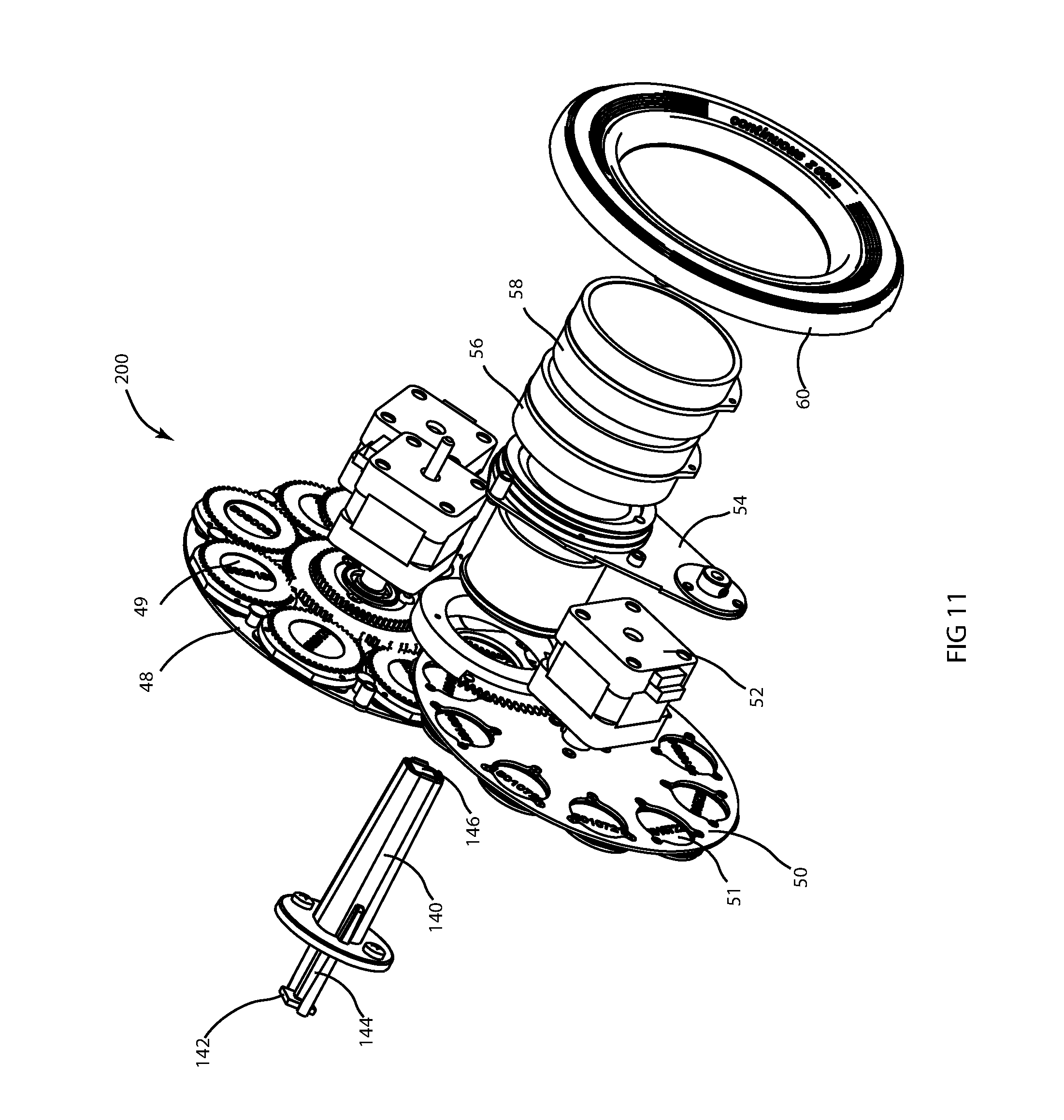
[0025] FIG. 11 illustrates the alternative embodiment of the light engine components of FIG. 8, FIG. 9 and FIG. 10 with the rest of the light engine major components; and
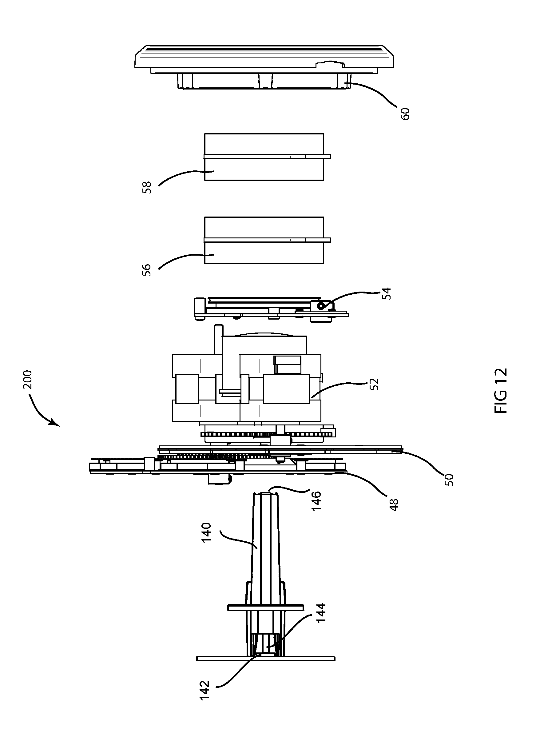
[0026] FIG. 12 illustrates a more detailed view of the light engine illustrated in FIG. 11.
DETAILED DESCRIPTION OF THE INVENTION
[0027] Preferred embodiments of the present invention are illustrated in the FIGUREs, like numerals being used to refer to like and corresponding parts of the various drawings.
[0028] The present invention generally relates to an automated luminaire, specifically to an optical system in an automated LED luminaire.
[0029] FIG. 2a illustrates the light module of an embodiment of the invention where an LED light source 24 is mounted to a support and heat sink 22. LED light source 24 may be fitted with its own optical element 20. Optical element 26 is an optional component in the system and, although illustrated here as a reflector, may be a reflector, TIR lens, lens, lens array, micro-lens array, holographic grating, diffractive grating, diffuser, or other optical device known in the art the purpose of which is to control and direct the light from LED light source 24 towards the entry port 40 of light integrator 30. LED light source element 24 may contain a single LED die or an array of LED dies utilizing the same optical element 20. Such arrays of LED dies within LED light source 24 may be of a single color and type or may be of multiple colors such as a mix of Red, Green and Blue LEDs. Any number and mix of colors of LED dies may be used within LED light source 24 without departing from the spirit of the invention. In a particular embodiment LED light source 24 may comprise a single multi-chip die containing separate red, green, blue, and white LED dies with a single primary optic 20.
[0030] Light integrator 30 is a device utilizing internal reflection so as to homogenize and constrain the light from LED light source 24. Light integrator 30 may be a hollow tube with a reflective inner surface such that light impinging into the entry port may be reflected multiple times along the tube before leaving at the exit port. As the light is reflected down the tube in different directions from LED light source 24 the light beams will mix forming a composite beam where different colors of light are homogenized and an evenly colored beam is emitted. Light integrator 30 may be a square tube, a hexagonal tube, a circular tube, an octagonal tube or a tube of any cross section known in the art. In a further embodiment light integrator 30 may be a solid rod constructed of glass, transparent plastic or other optically transparent material where the reflection of the incident light beam within the rod is due to total internal reflection (TIR) from the interface between the material of the rod and the surrounding air. Such integrating rods are well known in the art from their use in video projection illumination systems and may be circular or other polygonal shape in cross section.
[0031] The homogenized light exits 42 from the light integrator 30 and may then be further controlled and directed by optical system 44 and 46. Optical system 44 and 46 may be condensing lenses designed to produce an even illumination for downstream optics, or may be lenses that are adjustable to control the beam of the resultant light.
[0032] FIG. 2b illustrates an alternative light module of an embodiment of the invention where an LED light source 24 is mounted to a support and heat sink 22. LED light source 24 may be fitted with its own optical element 20. LED light source element 24 may contain a single LED die or an array of LED dies utilizing the same optical element 20. Such arrays of LED dies within LED light source 24 may be of a single color and type or may be of multiple colors such as a mix of Red, Green and Blue LEDs. Any number and mix of colors of LED dies may be used within LED light source 24 without departing from the spirit of the invention. In a particular embodiment LED light source 24 may comprise a single multi-chip die containing separate red, green, blue, and white LED dies with a single primary optic 20.
[0033] Light integrator 32 is a device utilizing internal reflection so as to homogenize and constrain the light from LED light source 24. Light integrator 32 may be a hollow tube with a reflective inner surface such that light impinging into the entry port may be reflected multiple times along the tube before leaving at the exit port. As the light is reflected down the tube in different directions from LED light source 24 the light beams will mix forming a composite beam where different colors of light are homogenized and an evenly colored beam is emitted. Light integrator 32 may be a square tube, a hexagonal tube, a circular tube, an octagonal tube or a tube of any cross section known in the art. In a further embodiment light integrator 32 may be a solid rod constructed of glass, transparent plastic or other optically transparent material where the reflection of the incident light beam within the rod is due to total internal reflection (TIR) from the interface between the material of the rod and the surrounding air. Such integrating rods are well known in the art from their use in video projection illumination systems and may be circular or other polygonal shape in cross section. Light integrator 32 may be tapered as shown here or may have parallel sides. Entry port 41 of light integrator 32 may be of a first cross section and exit port 43 may be of a second cross section. Entry cross section 41 and exit cross section 43 may be different shapes. In one embodiment entry cross section 41 is square and exit cross section 43 is octagonal. However entry cross section 41 and exit cross section 43 may be of any shape.
[0034] The homogenized light exits from the light integrator 32 and may then be further controlled and directed by optical system 44 and 46. Optical system 44 and 46 may be condensing lenses designed to produce an even illumination for downstream optics, or may be lenses that are adjustable to control the beam of the resultant light.
[0035] FIG. 3 illustrates an optical system 100 of an embodiment of the invention. The automated luminaire contains a light source as described in FIG. 2 that emits a collimated and homogenized light beam through optical system 44 and 46. The light beam then passes through multiple optical effects systems such as, for example, static gobo system 50, rotating gobo system 48, and prism system 54. The light beam then continues through lenses 56, 58, and 60 which may each individually or cooperatively be capable of movement along the optical axis of the luminaire so as to alter the focus and beam angle or zoom of the light beam.
[0036] Static gobo system 50, rotating gobo system 48, and prism system may be driven by motors 52 that may be stepper motors, servo motors. Linear actuators, or other motor systems as well known in the art. The luminaire may contain any number or combination of these optical effect systems as well as others such as framing systems, and diffusion systems.
[0037] Lenses 56, 58, and 60 may be chosen such that the output light beam from the automated luminaire is adjustable for both zoom and focus by moving any or all of lenses 56, 58, and 60 along the optical axis of the luminaire. In one embodiment of the invention the lenses and system are designed such that the beam is close to parallel and variable from 1.degree. to 10.degree. in angle. In the 10.degree. position the luminaire will be suitable for gobo projection, while in the 1.degree. position the luminaire will be suitable to be a beam effect projector.
[0038] FIG. 4 illustrates a perspective view of an embodiment of the invention illustrated in FIG. 3 that more clearly shows the static gobo wheel 50 containing gobos 51, and rotating gobo wheel 48 containing gobos 49.
[0039] The optical system 100 in FIGS. 3 and 4 has been elongated in illustration along the optical axis for ease of understanding. In practice the optical system 100 may be short from front to back allowing the production of a very compact automated luminaire.
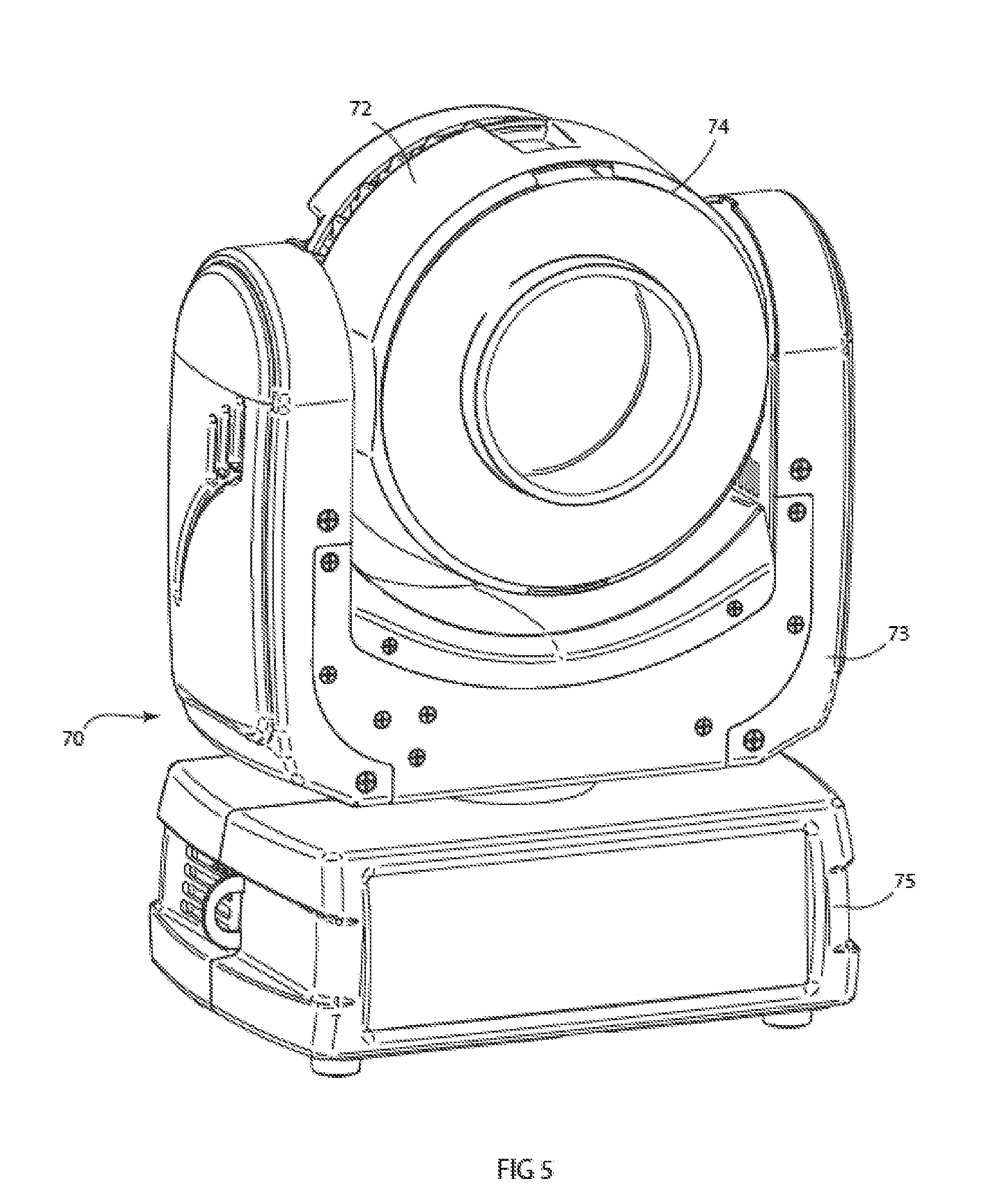
[0040] FIG. 5 illustrates an embodiment of an automated luminaire of the invention. Automated luminaire 70 comprises a base, 75, rotatably connected to a yoke assembly, 73, which in turn is rotatably connected to a head 72. The rotation of yoke 73 relative to the base 75 is often referred to as pan, and rotation of the head 72 relative to yoke 73 is often known as tilt. By combined and coordinated control of pan and tilt motions the head 72 may be pointed in any desired direction relative to fixed base 75.
[0041] Head 72 is fitted with an optical system as described and illustrated in FIGS. 3 and 4 of this document.
[0042] FIGS. 6, 7, 8, 9, and 10 illustrate an alternative embodiment of optical system 100 of the invention.
[0043] FIGS. 6 and 7 illustrate the operation of the optical system in an alternative embodiment of the invention. A light-emitting module of the system comprises an LED 142, which may include a primary optic, mounted on substrate 143. LED 142 may contain a single color die or may contain multiple dies, each of which may be of differing colors. The light output from the dies in LED 142 enters light integrator optic 144 contained within protective sleeve 140. Light integrator 144 may be a device utilizing internal reflection so as to collect, homogenize and constrain and conduct the light to exit port 146. Light integrator 144 may be a hollow tube with a reflective inner surface such that light impinging into the entry port may be reflected multiple times along the tube before leaving at the exit port 146. Light integrator 144 may be a square tube, a hexagonal tube, a heptagonal tube, an octagonal tube, a circular tube, or a tube of any other cross section. In a further embodiment light integrator 144 may be a solid rod constructed of glass, transparent plastic or other optically transparent material where the reflection of the incident light beam within the rod is due to total internal reflection (TIR) from the interface between the material of the rod and the surrounding air. The integrating rod may a square rod, a hexagonal rod, a heptagonal rod, an octagonal rod, a circular rod, or a rod of any other cross section.
[0044] The light exiting integrator 144 will be well homogenized with all the colors of LED 142 mixed together into a single colored light beam. In various embodiments of the invention each LED emitter 142 may comprise a single LED die of a single color or a group of LED dies of the same or differing colors. For example in one embodiment LED emitter 142 may comprise one each of a Red, Green, Blue and White LED die. In further embodiments LED emitter 142 may comprise a single LED chip or package while in yet further embodiments LED emitter 142 may comprise multiple LED chips or packages either under a single primary optic or each package with its own primary optic. In some embodiments these LED die(s) may be paired with optical lens element(s) as part of the LED light-emitting module. In a further embodiment LED emitter 142 may comprise more than four colors of LEDs. For example seven colors may be used, one each of a Red, Green, Blue, White, Amber, Cyan, and Deep Blue/UV LED die.
[0045] Integrator 144 may advantageously have an aspect ratio where its length is much greater than its diameter. The greater the ratio between length and diameter, the better the resultant mixing and homogenization will be. The precise length is dependent on the placement of LED color dies in the LED array served by the Integrator 144 to get Homogenization. One configuration may require a greater ratio of length to diameter to another and different configurations may require different input cross-sectional areas. and thus more length to get well mixed output. the shape of the cross sections and changes in the cross section also effect the length of integrator required. Integrator 144 may be enclosed in a tube or sleeve 140 that provides mechanical protection against damage, scratches, and dust.
[0046] In further embodiments the light integrator 144, whether solid or hollow, and with any number of sides, may have entry ports and exit ports that differ in shape. For example, a square entry port and an octagonal exit port 146. Further light integrator 144 may have sides which are tapered so that the entrance aperture is smaller than the exit aperture. The advantage of such a structure is that the divergence angle of light exiting the integrator 144 at exit port 146 will be smaller than the divergence angle for light entering the integrator 144. The combination of a smaller divergence angle from a larger aperture serves to conserve the etendue of the system. Thus a tapered integrator 144 may provide similar functionality to a condensing optical system.
[0047] Light exiting integrator 144 is directed towards and through first lens 136 and second lens 138 that serve to further control the angle of the emitted light beam. First lens 136 and second lens 138 may be moved as a pair towards and away from light integrator 144 as described above in the direction along the optical axis of the system as shown by arrow 132. In the position shown in FIG. 6 where first lens 136 and second lens 138 are at their furthest separation from the light-emitting module and the exit 146 of integrator 144 the emitted light beam will have a narrow beam angle. In the position shown in FIG. 7 where first lens 136 and second lens 138 are at their closest distance to the light-emitting module and the exit 146 of integrator 144 the emitted light beam will have a wide beam angle. Intermediate positions of the lenses 136 and 138 with respect to exit 146 of integrator 144 will provide intermediate beam angles. In one embodiment of the invention, the range of beam angles from the system may be adjusted from 4.degree. to 50.degree..
[0048] In further embodiments lenses 136 and 138 may move separately and independently to provide varying beam angle or focus adjustment of the light beam.
[0049] Lenses 136 and 138 may be meniscus lenses, plano convex lenses, bi-convex lenses, holographic lenses, or other lenses as well known in the art. Lenses 136 and 138 may be manufactured from glass, acrylic, polycarbonate, or any other material known to be used for optical lenses. Lenses 136 and 138 may be single elements or may each be lenses comprising a plurality of elements. Such elements may be cemented together or air spaced as is well known in the art. Lenses 136 and 138 may be constructed so as to form an achromatic combination. Such a configuration may be desirable such that the differing wavelengths of light from the associated LED light emitting module do not diverge or converge from each other and remain mixed. The design of such achromatic lenses or lens assemblies is well known in the art.
[0050] FIGS. 8 and 9 illustrate the operation of the optical system in an embodiment of the invention when fitted with effect 162. A light-emitting module of the system comprises an LED 142, which may include a primary optic, is mounted on substrate 143. LED 142 may contain a single color die or may contain multiple dies, each of which may be of differing colors. The light output from the dies in LED 142 enters light integrator optic 144 contained within protective sleeve 140. Light integrator 144 may be a device utilizing internal reflection so as to collect, homogenize and constrain and conduct the light to exit port 146. Light integrator 144 may be a hollow tube with a reflective inner surface such that light impinging into the entry port may be reflected multiple times along the tube before leaving at the exit port 146. Light integrator 144 may be a square tube, a hexagonal tube, a heptagonal tube, an octagonal tube, a circular tube, or a tube of any other cross section. In a further embodiment light integrator 144 may be a solid rod constructed of glass, transparent plastic or other optically transparent material where the reflection of the incident light beam within the rod is due to total internal reflection (TIR) from the interface between the material of the rod and the surrounding air. The integrating rod may a square rod, a hexagonal rod, a heptagonal rod, an octagonal rod, a circular rod, or a rod of any other cross section.
[0051] The light exiting integrator 144 will be well homogenized with all the colors of LED 142 mixed together into a single colored light beam. In various embodiments of the invention each LED emitter 142 may comprise a single LED die of a single color or a group of LED dies of the same or differing colors. For example in one embodiment LED emitter 142 may comprise one each of a Red, Green, Blue and White LED die or one each of a Red, Green, Blue and Amber LED die. In further embodiments LED emitter 142 may comprise a single LED chip or package while in yet further embodiments LED emitter 142 may comprise multiple LED chips or packages either under a single primary optic or each package with its own primary optic. In some embodiments these LED die(s) may be paired with optical lens element(s) as part of the LED light-emitting module. In a further embodiment LED emitter 142 may comprise more than four colors of LEDs. For example seven colors may be used, one each of a Red, Green, Blue, White, Amber, Cyan, and Deep Blue/UV LED die.
[0052] Integrator 144 may advantageously have an aspect ratio where its length is much greater than its diameter. The greater the ratio between length and diameter, the better the resultant mixing and homogenization will be. Integrator 144 may be enclosed in a tube or sleeve 140 that provides mechanical protection against damage, scratches, and dust.
[0053] In further embodiments the light integrator 144, whether solid or hollow, and with any number of sides, may have entry ports and exit ports that differ in shape. For example, a square entry port and an octagonal exit port 146. Further light integrator 144 may have sides which are tapered so that the entrance aperture is smaller than the exit aperture. The advantage of such a structure is that the divergence angle of light exiting the integrator 144 at exit port 146 will be smaller than the divergence angle for light entering the integrator 144. The combination of a smaller divergence angle from a larger aperture serves to conserve the etendue of the system. Thus a tapered integrator 144 may provide similar functionality to a condensing optical system.
[0054] Light exiting integrator 144 is directed towards and through effect 162 and then through first lens 136 and second lens 138 that serve to further control the angle of the emitted light beam. First lens 136 and second lens 138 may be moved as a pair towards and away from light integrator 144 as described above in the direction along the optical axis of the system as shown by arrow 132. In the position shown in FIG. 8 where first lens 136 and second lens 138 are at their furthest separation from the light-emitting module and the exit 146 of integrator 144 the emitted light beam will have a narrow beam angle. In the position shown in FIG. 9 where first lens 136 and second lens 138 are at their closest distance to the light-emitting module and the exit 146 of integrator 144 the emitted light beam will have a wide beam angle. Intermediate positions of the lenses 136 and 138 with respect to exit 146 of integrator 144 will provide intermediate beam angles. In one embodiment of the invention, the range of beam angles from the system may be adjusted from 4.degree. to 50.degree..
[0055] The introduction of effect 162 may limit how close first lens 136 and second lens 138 may move towards integrator 144. This, in turn, may limit the maximum output angle of the optical system when effect 162 is being utilized.
[0056] In further embodiments lenses 136 and 138 may move separately and independently to provide varying beam angle or focus adjustment of the light beam.
[0057] Lenses 136 and 138 may be meniscus lenses, plano convex lenses, bi-convex lenses, holographic lenses, or other lenses as well known in the art. Lenses 136 and 138 may be manufactured from glass, acrylic, polycarbonate, or any other material known to be used for optical lenses. Lenses 136 and 138 may be single elements or may each be lenses comprising a plurality of elements. Such elements may be cemented together or air spaced as is well known in the art. Lenses 136 and 138 may be constructed so as to form an achromatic combination. Such a configuration may be desirable such that the differing wavelengths of light from the associated LED light emitting module do not diverge or converge from each other and remain mixed. The design of such achromatic lenses or lens assemblies is well known in the art.
[0058] FIG. 10 illustrates an effects system that may be fitted to an embodiment of the invention. The light emitting module comprises, as previously described, LED 142, light integrator 144 with exit 146 contained within tube 140. Associated with this light emitting module are lenses 136 and 138. The light-emitting module additionally has a lighting effects system. This lighting effects system comprises optical effect 162 that is rotatably mounted in effects carrier arm 160 such that it can rotate as shown by arrow 164. This rotation 164 is effected through motor 150 and pulley system 158. Additionally, the effect carrier arm may be swung into and out of position through motor 152, pulley 154, and belt 156. Through operation of motor 152 optical effect 162 may either be positioned across light exit aperture 146 or moved away from light exit aperture 146 and out of the light beam so that it has no effect. Once effect 162 is in position across the light beam, lenses 136 and 138 may be moved in direction 132 as before to alter the beam angle of the light beam, now further modified by effect 162. Motors 150, and 152 may be stepper motors, servo motors, linear actuators, solenoids, DC motors, or other mechanisms as well known in the art.
[0059] Effect 162 may be a prism, effects glass, gobo, gobo wheel, color, frost, iris or any other optical effect as well known in the art. Effect 162 may comprise a gobo wheel, all or any of which may be individually or cooperatively controlled. In further embodiments the gobo wheel may not be a complete circle, but may be a portion of a disc, or a flag so as to save space and provide a more limited number of gobo options. The gobo patterns may be of any shape and may include colored images or transparencies. In yet further embodiments individual gobo patterns may be further rotated about their axes by supplementary motors in order to provide a moving rotating image. Such rotating gobo wheels are well known in the art.
[0060] In further embodiments lenses 136 and 138 may move separately and independently to provide varying beam angle or focus adjustment of the light beam.
[0061] Lenses 136 and 138 may be meniscus lenses, plano convex lenses, bi-convex lenses, holographic lenses, or other lenses as well known in the art. Lenses 136 and 138 may be manufactured from glass, acrylic, polycarbonate, or any other material known to be used for optical lenses. Lenses 136 and 138 may be single elements or may each be lenses comprising a plurality of elements. Such elements may be cemented together or air spaced as is well known in the art. Lenses 136 and 138 may be constructed so as to form an achromatic combination. Such a configuration may be desirable such that the differing wavelengths of light from the associated LED light emitting module do not diverge or converge from each other and remain mixed. The design of such achromatic lenses or lens assemblies is well known in the art.
[0062] FIGS. 11 and 12 illustrate an optical system 200 of an embodiment of the invention. The automated luminaire contains a light source as described in FIGS. 6 and 7 that emits a collimated and homogenized light beam from exit aperture 146. The light beam then passes through multiple optical effects systems such as, for example, static gobo system 50 containing gobos 51, rotating gobo system 48 containing gobos 49, and prism system 54. The light beam then continues through lenses 56, 58, and 60 which may each individually or cooperatively be capable of movement along the optical axis of the luminaire so as to alter the focus and beam angle or zoom of the light beam.
[0063] Static gobo system 50, rotating gobo system 48, and prism system may be driven by motors 52 that may be stepper motors, servo motors. Linear actuators, or other motor systems as well known in the art. The luminaire may contain any number or combination of these optical effect systems as well as others such as framing systems, and diffusion systems.
[0064] Lenses 56, 58, and 60 may be chosen such that the output light beam from the automated luminaire is adjustable for both zoom and focus by moving any or all of lenses 56, 58, and 60 along the optical axis of the luminaire. Lenses 56, 58 and 60 may be comprised of meniscus lenses, plano convex lenses, bi-convex lenses, holographic lenses, or other lenses as well known in the art. Lenses 56, 58 and 60 may be manufactured from glass, acrylic, polycarbonate, or any other material known to be used for optical lenses. Lenses 56, 58 and 60 may be single elements or may each be lenses comprising a plurality of elements. Such elements may be cemented together or air spaced as is well known in the art. Lenses 56, 58 and 60 may be constructed so as to form an achromatic combination. Such a configuration may be desirable such that the differing wavelengths of light from the associated LED light emitting module do not diverge or converge from each other and remain mixed. The design of such achromatic lenses or lens assemblies is well known in the art.
[0065] In one embodiment of the invention the lenses and system are designed such that the beam is close to parallel and variable from 1.degree. to 10.degree. in angle. In the 10.degree. position the luminaire will be suitable for gobo projection, while in the 1.degree. position the luminaire will be suitable to be a beam effect projector.
[0066] The optical system 200 in FIGS. 11 and 12 has been elongated in illustration along the optical axis for ease of understanding. In practice the optical system 200 may be short from front to back allowing the production of a very compact automated luminaire.
[0067] While the disclosure has been described with respect to a limited number of embodiments, those skilled in the art, having benefit of this disclosure, will appreciate that other embodiments may be devised which do not depart from the scope of the disclosure as disclosed herein. The disclosure has been described in detail, it should be understood that various changes, substitutions and alterations can be made hereto without departing from the spirit and scope of the disclosure.
* * * * *
D00000
D00001
D00002
D00003
D00004
D00005
D00006
D00007
D00008
D00009
D00010
XML
uspto.report is an independent third-party trademark research tool that is not affiliated, endorsed, or sponsored by the United States Patent and Trademark Office (USPTO) or any other governmental organization. The information provided by uspto.report is based on publicly available data at the time of writing and is intended for informational purposes only.
While we strive to provide accurate and up-to-date information, we do not guarantee the accuracy, completeness, reliability, or suitability of the information displayed on this site. The use of this site is at your own risk. Any reliance you place on such information is therefore strictly at your own risk.
All official trademark data, including owner information, should be verified by visiting the official USPTO website at www.uspto.gov. This site is not intended to replace professional legal advice and should not be used as a substitute for consulting with a legal professional who is knowledgeable about trademark law.