A Wellbore System, Tool And Method
ESPE; Eirik ; et al.
U.S. patent application number 16/098909 was filed with the patent office on 2019-06-27 for a wellbore system, tool and method. This patent application is currently assigned to WELLGUARD AS. The applicant listed for this patent is WELLGUARD AS. Invention is credited to Eirik ESPE, Fridtjof NYHAVN.
| Application Number | 20190195062 16/098909 |
| Document ID | / |
| Family ID | 58993179 |
| Filed Date | 2019-06-27 |


| United States Patent Application | 20190195062 |
| Kind Code | A1 |
| ESPE; Eirik ; et al. | June 27, 2019 |
A WELLBORE SYSTEM, TOOL AND METHOD
Abstract
A well tool having a body configured for deployment in a tubular in a wellbore and having connection means (2; 2a) configured for connection to running 12 tools and control means (3) for connection to uphole control means, characterized 13 by a magnetic field generator (5) configured and controllable by the control means to generate a time--varying magnetic field. Use of the tool as a wellbore heating tool, a cement verification tool or a wellbore plugging tool.
| Inventors: | ESPE; Eirik; (Tyssedal, NO) ; NYHAVN; Fridtjof; (Trondheim, NO) | ||||||||||
| Applicant: |
|
||||||||||
|---|---|---|---|---|---|---|---|---|---|---|---|
| Assignee: | WELLGUARD AS Tyssedal NO |
||||||||||
| Family ID: | 58993179 | ||||||||||
| Appl. No.: | 16/098909 | ||||||||||
| Filed: | May 5, 2017 | ||||||||||
| PCT Filed: | May 5, 2017 | ||||||||||
| PCT NO: | PCT/NO2017/050110 | ||||||||||
| 371 Date: | November 5, 2018 |
| Current U.S. Class: | 1/1 |
| Current CPC Class: | E21B 33/134 20130101; E21B 43/24 20130101; E21B 43/2401 20130101; E21B 37/00 20130101; E21B 33/1208 20130101; E21B 36/00 20130101; E21B 47/005 20200501 |
| International Class: | E21B 47/00 20060101 E21B047/00; E21B 33/12 20060101 E21B033/12; E21B 33/134 20060101 E21B033/134; E21B 43/24 20060101 E21B043/24 |
Foreign Application Data
| Date | Code | Application Number |
|---|---|---|
| May 6, 2016 | NO | 20160763 |
Claims
1. A well tool comprising: a body configured for deployment in a tubular in a wellbore and comprising a connection means configured for connection to running tools; down, controller configured to connect to an uphole controller; and a magnetic field generator configured and controllable by at least one of the downhole controller or the uphole controller to generate a time-varying magnetic field.
2. (canceled)
3. The well tool of claim 1, wherein the magnetic field generator comprises a rotatable member connected to a controllable drive means and comprising a plurality of permanent magnets assembled on at least a portion of the rotatable member, the permanent magnets having alternating polarity.
4. (canceled)
5. The well tool of claim 3, wherein the rotatable member comprises a cylindrical, frusto-conical or spherical shape and the plurality of permanent magnets comprises a plurality of first and second permanent magnets that are assembled at regular intervals on at least a portion of the rotatable member outer surface.
6. The well tool of claim 3, wherein the rotatable member comprises a drum shape and the plurality of permanent magnets comprises a plurality of first and second permanent magnets that are assembled at regular intervals on an end surface of said drum and concentric with a drum axis of rotation.
7. The well tool of claim 3, wherein the drive means comprises at least one of an electric motor and controllable power source or a turbine configured for connection to a fluid conduit and controllably operated by means of an injected fluid.
8. (canceled)
9. The well tool claim 1, wherein the tool comprises a housing enclosing at least the magnetic field generator; said housing comprising a material which is not significantly electrically conducting.
10. The well tool claim 1, wherein the tool comprises a housing enclosing at least the magnetic field generator; said housing comprising an electrically conducting material, wherein the housing is heated when the magnetic field generator is operated.
11. The well tool claim 1, further comprising an element comprising an electrically conducting and eutectic material arranged on the tool such that the element is influenced by the time-varying magnetic field generated by the magnetic field generator.
12. (canceled)
13. The well tool of claim 11, wherein the element comprises a sleeve encircling at least a portion of the tool body.
14. (canceled)
15. The well tool of claim 1, further comprising a sensor means for sensing at least one of rotational moments or electrical currents in the magnetic field generator.
16. (canceled)
17. (canceled)
18. (canceled)
19. A wellbore tubular comprising at least one element having an electrically conducting and eutectic material that is arranged on at least a portion of the tubular.
20. (canceled)
21. (canceled)
22. (canceled)
23. The wellbore tubular of claim 19, wherein the element is a sleeve which has been pre-installed on the tubular prior to the tubular being introduced into the wellbore.
24. A wellbore system comprising a well tool comprising: a body configured for deployment in a tubular in a wellbore and comprising a connection means configured for connection to running tools, a downhole controller configured to connect to an uphole controller, and a magnetic field generator configured and controllable by at least one of the downhole controller or the uphole controller to generate a time-varying magnetic field: and a wellbore tubular comprising least one element having an electrically conducting and eutectic material that is arranged on at least a portion of the tubular.
25. The wellbore system of claim 24, wherein said at least one tool is arranged proximal to at least one element, wherein at least a portion the element is influenced by a time-varying magnetic field generated by the magnetic field generator when the tool is operated.
26. A method of sealing an annular region in a wellbore comprising at least one wellbore tubular, the method comprising: conveying a well tool to a location in the tubular proximal to at least one element; operating the well tool to generate a time-varying magnetic field, at a sufficient magnitude and duration until the element material reaches its melting temperature; allowing the molten material to flow to a desired location; and allowing the material to cool to a solid state, sealing, material.
27. A method of forming a plug in a tubular, the method comprising: conveying a well tool to a location in the tubular; operating the well tool to generate a time-varying magnetic field, at a sufficient magnitude and duration until the element material reaches its melting temperature; allowing the molten material to settle on a plug foundation; and allowing the material to cool to a solid state, sealing, material in the entire tubular cross-section.
28. The method of claim 27, further comprising flowing molten material through at least one opening in the tubular wall, thereby forming a bridge plug extending into the annulus formed between the tubular outer wall and an adjacent formation or other tubular.
29. A method of heating well fluids in a tubular the method comprising: conveying the a well tool to a desired location in the tubular; and operating the well tool to generate a time-varying magnetic field, at a sufficient magnitude and duration until the housing has reached a desired temperature.
30. The method of claim 29, further comprising: conveying the well tool to a vicinity of obstructive matters; and operating the well tool until such matter is melted or substantially dissolved.
31. (canceled)
32. A method of verifying wellbore cement, the method comprising conveying a well tool (1e) to a downhole location proximal to said cement; operating the well tool to generate a time-varying magnetic field; sensing rotational moments of a rotating cylinder or measure the electrical current in a coil array; calculate the energy loss due to any conductive material in the cement.
Description
FIELD OF THE INVENTION
[0001] The invention concerns a well tool as set out in the preamble to claim 1, a wellbore tubular as set out in the preamble to claim 19, a wellbore system as set out in the preamble to claim 24, and methods as set out in the preambles to claims 26, 27, 29 and 32.
BACKGROUND OF THE INVENTION
[0002] Cement is widely used as a barrier substance in subterranean wells, both to form a seal between the well casing and the surrounding formation (as a part of the well completion), and as a plugging substance inside liners or/and in annuli between downhole tubulars (e.g. when the well is to be plugged and abandoned). A disadvantage of cement, resins and similar substances is their tendency to shrink upon solidification, as well as their propensity to crack and otherwise deteriorate over time and when subjected to downhole pressures and movements in the surrounding formation. Also, as the tubular walls often are contaminated by oily substances, the adherence between such plugging or sealing substance and the tubular wall may be weak. Therefore, plugs formed by cement, resins or similar substances are susceptible to leaking. This is unacceptable from operational and environmental reasons, and entail meticulous monitoring and if necessary costly re-plugging operations.
[0003] As an alternative to using cement and similar substances, as described above, alloys containing bismuth are increasingly being used to form lasting, fluid-tight barriers and plugs in subterranean wellbores. The bismuth alloy is introduced into the wellbore in a solid state and placed at the desired downhole location, then subjected to a heat source whereby the alloy melts. The bismuth alloy is then allowed to cool and solidify as a plug in the tubular. One advantage of bismuth alloys is their inherent characteristic of expanding upon solidification, whereby the material penetrates into cracks and fissures. The bismuth alloy, having a high melting temperature, also effectively creates a metal-to-metal seal interface with the tubular wall.
[0004] The prior art includes WO 02/099247 A1 (Shell), which describes a method of creating a gas-tight well abandonment sealing plug by placing a metal which expands upon solidification in the well, melting the metal, and cooling down the metal to solidify it. The metal may be an expanding alloy, which expands upon solidification and has a melting temperature that is higher than the maximum anticipated well temperature. The expanding alloy may comprise bismuth, gallium or antimony. The metal may be in the form of bismuth or bismuth alloy rings that are conveyed into the wellbore on a tubular tool body, and heat is applied from within that body. The heat may be provided by a chemical source of heat, electric (resistive or inductive) heater, or through conductions of a hot liquid (e.g. steam) inside the tubular tool body. The heat will increase the temperature of the rings until eventually both rings will melt and sag to the lowest point in the annulus by gravity.
[0005] The prior art also includes WO 02/27137 A1 (Rawwater Engineering), which describes a well sealing method and apparatus in which a length of the well is filled with a molten material having a melting point which is higher than the temperature within the well and which expands as it solidifies. The material may be a metal alloy, for example a low-melting point bismuth-containing alloy such as "Rose's metal" (melting temperature 93.degree. C.), "Kraft's alloy" (melting temperature 104.degree. C.) or "Homberg's alloy" (melting point 122.degree. C.). The bismuth-containing alloy may be doped with sodium. Such alloys expand upon solidification and thus once deposited in a well they lose heat into the surrounding environment, solidify, and in solidifying expand to form a secure plug within the well. The material may be delivered to the well in a molten state. For example, a canister of molten material may be lowered to the intended site of the plug and opened either by remote control or deliberate rupture of the canister. Alternatively, the material may be delivered to the well in a solidified state, subsequently melted in the well, and then allowed to solidify. For example, the material could be delivered in granular form, for example in a carrier fluid. The granular material could then be melted in any suitable manner, thereafter cooling to form a solidified plug. As a further alternative the plug material may be delivered to the well and located there within mounted in solid form on a carrier. Such a carrier may comprise a chemical heater, for example a thermite mixture, which when ignited provides thermal energy to melt the plug material when it is located at the required well depth. The carrier may incorporate an engagement means to engage the well casing when in position. Such engagement means may be arranged to allow insertion of the carrier into the well and movement in a down-hole direction therein but prevent up-hole movement. This may be achieved by coupling the engagement means to the carrier via a hinge. Non-chemical methods of melting the plug material could be for example steam, heated water, electrical resistance heating, frictional heating, sonothermic (sound generated) heating, cavitational (pressure generated) heating, or even simply introducing a solid high thermal capacity mass from which heat is transferred into the previously deposited granular material.
[0006] The prior art also includes WO 2014/096858 A2 (BISN TEC), which describes an apparatus for plugging oil and gas wells by means of bismuth-based or other eutectic plugs. A plug deployment assembly comprises a plug body holding a bismuth-based alloy, a heater and an igniter wire. The heater is releasably engaged within the plug body so that the heater can be retrieved from the plug body once it has been fixed into a well and the eutectic alloy plug has formed. The heater, which is preferably a thermite-based chemical reaction source heater, is provided with a heater core and an igniter/initiator. The heater is attached to the igniter wire so that the assembly can be delivered down a well and then the heater can be subsequently retrieved. The igniter wire is connected to a standard wireline connector, to enable the remote operation from ground level. In one embodiment, the alloy might be a germanium/bismuth alloy, which has a higher melting temperature than other bismuth based alloys. The higher melting temperatures of such alloys make them particularly suitable for plugging deeper underground where the subterranean environment is hotter. In such applications it is appreciated that a chemical heater is required due to the increased level of heat required to melt the alloy (e.g. 550.degree. C.). In particular it is appreciated that a chemical reaction heat source with a fuel composition comprising a mix of thermite and a damping agent would be particularly preferable, with solid mixes of these fuel compositions being especially desirable.
[0007] A disadvantage common to the heating methods described above is that structures and materials other than the bismuth alloy are also heated. For example, the stainless steel casings and couplings may expand when subjected to the heat, and thus become deformed or separated from the adjoining formation or barrier material. Another disadvantage of the prior art heating methods is the lack of real-time control of the heat generation. For example, while a chemical reaction heat source (such as thermite) may be designed and dimensioned for a specific application, it is not possible to adjust the heat energy released by such a heat source once it has been activated downhole. It is therefore a need for an improved heating method.
[0008] A well-known problem associated with the production of hydrocarbons from subterranean well is the formation of various flow obstructions. Emulsions, and substances such as wax and asphaltenes, may form in downhole wellbores, for example inside production tubings and on the outside of liners, thereby restricting flow in the tubulars and/or from the surrounding formation. In subsea flowlines and risers, and in wellbores having low temperatures, flow obstructions in the form of hydrates represents a considerable problem.
[0009] Most such flow obstructions are removed by common cleanup flow with various chemical additives (like acids). However, some residual problems may occur and obstructing deposits like paraffin, asphaltenes and salt may then be treated with heat (hot water; steam, etc.). Flowlines with embedded heat tracing are also known. It is therefore a need for a more efficient and versatile tool for removing such flow obstructions.
[0010] Another problem associated with hydrocarbon wells is the continual need to verify the cement quality and the bonding between the cement and the casing(s), in order to prevent or curtail well fluid leaks. This becomes of particular importance when a well is to sealed off (plugged) and abandoned. In the prior art, cement verification is based on sonic techniques, analyzing pressure waves or shear waves. These techniques have limitations, especially for cement evaluation for light cements, thick casings and the ability to provide information about the so-called "Third Interface", i.e. between the cement/formation or cement/next casing. Such information can provide valuable information about wellbore integrity during production and later plugging-and-abandonment (P&A) operations. It is therefore a need for an improved cement verification method.
SUMMARY OF THE INVENTION
[0011] The invention is set forth and characterized in the main claim, while the dependent claims describe other characteristics of the invention.
[0012] It is thus provided a well tool, having a body configured for deployment in a tubular in a wellbore and having connection means configured for connection to running tools and control means for connection to uphole control means, characterized by a magnetic field generator configured and controllable by the control means to generate a time-varying magnetic field.
[0013] In one embodiment, the magnetic field generator comprises an AC electromagnet or transformer.
[0014] In one embodiment, the magnetic field generator comprises a rotatable member having a plurality of permanent magnets assembled on at least a portion of the rotatable member, and with alternating polarity; and the rotatable member is connected to controllable drive means. The rotatable member may have a cylindrical shape, and a plurality of first and second permanent magnets assembled at regular intervals on at least a portion of the cylindrical member perimeter. In one embodiment, the rotatable member has a conical, frusto-conical or spherical shape, and a plurality of first and second permanent magnets are assembled at regular intervals on at least a portion of the rotatable member outer surface.
[0015] The rotatable member may have a drum shape, and a plurality of first and second permanent magnets are assembled at regular intervals on an end surface of said drum, concentric with a drum axis of rotation.
[0016] In one embodiment, the drive means comprises an electric motor and controllable power means.
[0017] In one embodiment, the drive means comprises a turbine configured for connection to a fluid conduit, whereby the turbine is controllably operated by means of an injected fluid.
[0018] In one embodiment, the tool comprises a housing enclosing at least the magnetic field generator; said housing being of a material which is not significantly electrically conducting.
[0019] In one embodiment, the tool comprises a housing enclosing at least the magnetic field generator; said housing being of an electrically conducting material, whereby the housing is heated when the magnetic field generator is operated.
[0020] The well tool may comprise an element having an electrically conducting and eutectic material arranged on the tool such that the element is influenced by the time-varying magnetic field generated by the magnetic field generator. In one embodiment, the element material comprises a bismuth alloy. The element may be a sleeve encircling at least a portion of the tool body.
[0021] In one embodiment, the well tool further comprises anchor means for releasably fixating the tool in a tubular element.
[0022] In one embodiment, the well tool further comprises sensor means for sensing rotational moments or electrical currents in the magnetic field generator.
[0023] In one embodiment, the invented well tool may be used as a wellbore heating tool.
[0024] In one embodiment, the invented well tool may be used as a cement verification tool.
[0025] In one embodiment, the invented well tool may be used as a wellbore plugging tool.
[0026] It is also provided a wellbore tubular, characterized in that least one element having an electrically conducting and eutectic material is arranged on at least a portion of the tubular. The element may be is arranged on at least a portion of the tubular outer wall. In one embodiment, the tubular is a production tubing. In one embodiment, the tubular is a steel casing. In one embodiment, the electrically conducting and eutectic material comprises a bismuth alloy. The element may be a sleeve which has been pre-installed on the tubular prior to the tubular being introduced into the wellbore.
[0027] It is also provided a wellbore system, characterized by at least one of the invented wellbore tool being arranged in the invented wellbore tubular. The tool is arranged proximal to at least one element, whereby at least a portion the element is influenced by a time-varying magnetic field generated by the magnetic field generator when the tool is operated.
[0028] It is also provided a method of sealing an annular region in a wellbore comprising at least one wellbore tubular according to the invention, characterized by:
[0029] i) conveying the tool according to the invention to a location in the tubular proximal to at least one element;
[0030] ii) operating the tool to generate a time-varying magnetic field, at a sufficient magnitude and duration until the element material reaches its melting temperature;
[0031] iii) allowing the molten material to flow to a desired location; and
[0032] iv) allowing the material to cool to a solid state, sealing, material.
[0033] It is also provided a method of forming a plug in a tubular, characterized by:
[0034] i) conveying the tool according to the invention to a location in the tubular;
[0035] ii) operating the tool to generate a time-varying magnetic field, at a sufficient magnitude and duration until the element material reaches its melting temperature;
[0036] iii) allowing the molten material to settle on a plug foundation; and
[0037] iv) allowing the material to cool to a solid state, sealing, material in the entire tubular cross-section. The method may comprise flowing molten material through at least one opening in the tubular wall, thereby forming a bridge plug extending into the annulus formed between the tubular outer wall and an adjacent formation or other tubular.
[0038] It is also provided a method of heating well fluids in a tubular, characterized by:
[0039] i) conveying an embodiment of the tool comprising a housing enclosing at least the magnetic field generator (said housing being of an electrically conducting material, whereby the housing is heated when the magnetic field generator is operated) to a desired location in the tubular;
[0040] ii) operating the tool to generate a time-varying magnetic field, at a sufficient magnitude and duration until the housing has reached a desired temperature.
[0041] The tool may be conveyed to a vicinity of obstructive matters, and operated until such matter is melted or substantially dissolved. The matter may comprise, wax, asphaltenes, or hydrates.
[0042] It is also provided method of verifying wellbore cement, characterized by
[0043] i) conveying an embodiment of the tool according to the invention to a downhole location proximal to said cement;
[0044] ii) operating the tool to generate a time-varying magnetic field;
[0045] iii) sensing rotational moments of a rotating cylinder or measure the electrical current in a coil array;
[0046] iv) calculate the energy loss due to any conductive material in the cement.
[0047] Thus, by controlling the time-varying magnetic field generated by the invented tool, the temperature generated by the resulting eddy currents is also controlled. In one embodiment, the time-varying magnetic field is generated and controlled by controlling the rotational speed of the cylinder.
[0048] The invention allows a real-time remote control of a heating process, which is particularly useful for melting of the bismuth alloy. Another advantage is that the heat required to melt the bismuth alloy is generated within the bismuth alloy, and that only insignificant heat is generated within surrounding structures (such as steel casings and couplings), thereby avoiding the unwanted effects of thermal expansion in such structures.
[0049] The invention also provides an effective tool and method for removing obstructions in is the wellflow, such as wax and asphaltene deposits and slugs.
[0050] The invention also provides an efficient tool and method for verifying annular cement and cement/casing bonding.
BRIEF DESCRIPTION OF THE DRAWINGS
[0051] These and other characteristics of the invention will become clear from the following description of various embodiments, given as non-restrictive examples, with reference to the attached schematic drawings, wherein:
[0052] FIG. 1 is a side view of a first embodiment of the tool according to the invention;
[0053] FIG. 2 is a partial cutaway drawing of the tool illustrated in FIG. 1, illustrating i.a. a rotatable cylinder having a plurality of magnets;
[0054] FIG. 3a shows the tool of FIG. 2, installed in a tubular, for example a production tubing, having a bismuth alloy sleeve on a portion of the tubular outer wall;
[0055] FIG. 3b corresponds to FIG. 3a, but illustrates how the bismuth alloy sleeve, having been melted by the tool and thus flowed off the tubular, has solidified on a packer;
[0056] FIG. 4a shows the tool of FIG. 2, installed in a tubular, for example a steel casing, having a sleeve of bismuth alloy or other electrical conducting and eutectic material on a portion of the casing outer wall;
[0057] FIG. 4b corresponds to FIG. 4a, but illustrates how the bismuth alloy sleeve, having been melted by the tool and thus flowed off the casing, has solidified on annular concrete between the casing and the formation (or other casing);
[0058] FIGS. 5a and 5b correspond to FIGS. 4a and 4b, with the exception that the tool is arranged within a production tubing;
[0059] FIGS. 6a and 6b are a side view and a sectional view, respectively, of a second embodiment of the tool according to the invention;
[0060] FIG. 6c is a top view of the tool illustrated by FIG. 6b;
[0061] is FIG. 6d shows the tool illustrated in FIG. 6a, run on a workstring and in operation in a tubular, for example a steel casing, having a sleeve of bismuth alloy or other electrical conducting and eutectic material on a portion of the casing outer wall;
[0062] FIG. 7a is a partly cutaway drawing of a third embodiment of the tool according to the invention, having a sleeve of bismuth alloy or other electrical conducting and eutectic material installed around a portion of its body; and the tool is in operation within a steel casing;
[0063] FIG. 7b corresponds to FIG. 7a, but shows that bismuth alloy, having been melted off the tool, has solidified and formed a plug inside the casing;
[0064] FIG. 8a is partly cutaway drawing of a fourth embodiment of the tool according to the invention, illustrating i.a. a rotatable cylinder, and the tool comprising a housing of a material having a suitable electrical conductivity, whereby the housing is heated when the cylinder is rotated and effectively is a "heat cap";
[0065] FIG. 8b is a partly cutaway drawing of the tool shown in FIG. 8a, seen from below, and illustrating a plurality of magnets arranged on the rotatable cylinder;
[0066] FIGS. 8c and 8d show the tool of FIGS. 8a and 8b in operation inside a production tubing to remove obstructive materials from the tubing;
[0067] FIGS. 9a and 9b are a side view and a sectional view, respectively, of a fifth embodiment of the tool according to the invention, having a heat cap;
[0068] FIGS. 9c and 9d show the tool of FIGS. 9a and 9b in operation inside a production tubing to remove obstructive materials from the tubing; and
[0069] FIG. 10 is partly cutaway drawing of a sixth embodiment of the tool according to the invention, illustrating i.a. a rotatable cylinder, installed in a tubing in a wellbore.
DETAILED DESCRIPTION OF EMBODIMENTS
[0070] The following description may use terms such as "horizontal", "vertical", "lateral", "back and forth", "up and down", "upper", "lower", "inner", "outer", "forward", "rear", etc. These terms generally refer to the views and orientations as shown in the drawings is and that are associated with a normal use of the invention. The terms are used for the reader's convenience only and shall not be limiting.
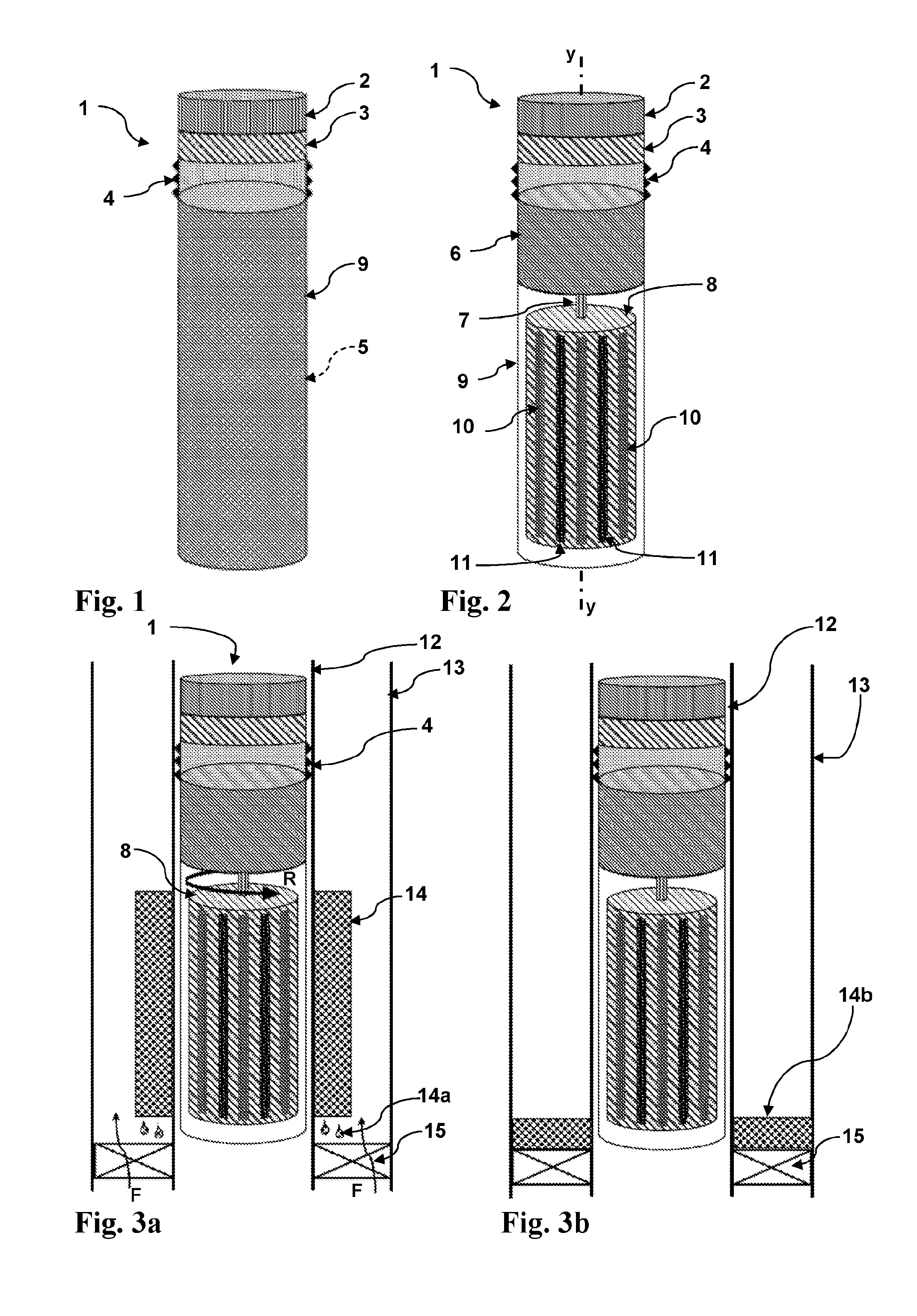
[0071] FIG. 1 is a schematic illustration of a first embodiment of the invented tool 1. The tool is designed and configured for being run in a subterranean wellbore and comprises a cylindrical body with a connection head assembly 2 by means of which the tool may be connected to a running tool (e.g. wireline; not shown) that are well known in the art. The tool furthermore comprises a power, control, and communications module 3 by means of which the tool may be operated. Although not illustrated, the tool comprises sensors, connected to the module 3, configured for monitoring ambient temperatures. It should be understood that the module 3 may have a battery pack, or the tool may be powered from a surface (uphole) location via power cables. Various means for powering and operating downhole tools are known to the skilled person, including wires, cables and connections, and need therefore not be described in detail here. The tool body comprises anchors (e.g. slips) 4, by means of which the tool may be releasably installed in a tubular, for example a production tubing or a casing. Such anchors, and their method of operation, are well known in the art, and need therefore not be described in further detail here. It should be understood that, as FIG. 1 is a schematic drawing, more anchors may be required, for example at the lower end of the tool, in order to sufficiently fixate the tool during operation.
[0072] The tool furthermore comprises a housing 9, of a material that is only negligibly affected by magnetic fields and does not have too high an electrical conductivity (in order to minimize generation of eddy currents in the housing material). Examples of such materials are plastics, carbon fibers and resins. In the following, such materials will be referred to as "non-magnetic materials".
[0073] The tool 1 also comprises a magnetic field generator 5, inside the non-magnetic housing 9. The magnetic field generator 5 may be any device configured to generate a time-varying magnetic field, for example by means of an AC electromagnet or transformer, or by relative motion between a magnet and a nearby conductor. The magnetic field generator is controllable from an uphole (surface) location via communication means that per se are known in the art.
[0074] Referring to FIG. 2, the magnetic field generator comprises in a first embodiment a cylinder 8 which is rotatably connected to a drive unit 6 via an axle 7. A non-magnetic housing 9 encloses the cylinder 8 in order to protect it from physical downhole obstructions (which may prevent rotation), but the invention shall not be limited to the use of such housing.
[0075] In the illustrated embodiment, it is envisaged that the drive unit 6 is an electric motor, but other drive units may also be used. The cylinder rotation is controllable from an uphole (surface) location via communication means that per se are known in the art. The cylinder is arranged to rotate around the tool longitudinal axis y-y. It should be understood that, as FIG. 2 is a schematic drawing, also a lower axle and a corresponding bearing may be required in order to ensure a stable rotation of the cylinder 8. The design and operation of the rotatable cylinder may, however, be accomplished in a number of ways, well known in the art.
[0076] Arranged on the cylinder 8 is a plurality of permanent magnets 10, 11, generally aligned with the tool longitudinal axis y-y. Each magnet has an elongated "stick-like" shape, and may be affixed to the cylinder in a manner which per se is known in the art, but with sufficient adherence to withstand large centrifugal forces. For example, the magnets may be fastened to the cylinder surface by a strong adhesive. In another configuration (not illustrated), the magnets may be arranged and retained by elastic members (e.g. springs) inside respective recesses; from which they are extended by virtue of the centrifugal force when the cylinder is spinning. This configuration may be particularly useful if the tool is operated without a cylinder housing, whereby a greater tool drift is tolerated.
[0077] Each magnet 10, 11 generates a magnetic field pointing radially outwards from the cylinder. The magnets 10, 11 may be of a similar design and have similar magnetic properties, but are assembled on the cylinder with their polarity in alternating directions, such that the magnetic poles shift for every other magnet around the entire cylinder circumference when the cylinder rotates. In FIG. 2 (as well as in the figures following) this is indicated by reference number 10 denoting a first magnet (i.e. having a first orientation) and reference number 11 denoting a second magnet (i.e. having a second orientation). Although not illustrated explicitly in the side view of FIG. 2, it should be understood that the magnets 10, 11 are arranged equally spaced around the cylinder circumference)(360.degree., with alternating orientations. The number of magnets arranged around the cylinder, and their magnetic field strength, may be determined based on the application at hand, but it is envisaged that at least one first magnet 10 and at least one second magnet 11 are required.
[0078] In operation, when the cylinder is rotated, the alternating-magnet configuration will emit an alternating magnetic field. The emitted alternating magnetic field may be augmented by known means and devices, for example by magnets configured in a so-called Halbach array.
[0079] Turning now to FIG. 3a, the tool 1 is installed (via anchors 4) in a tubing, for example a downhole production tubing 12. The production tubing 12 is installed in another tubing, which may be a steel casing 13, by means of production packers 15 (only one shown in FIG. 2). As is well known, such production packers are prone to leaking wellfluid, indicated by arrows F. Arranged on a portion of the outer wall of the production tubing 12, is a sleeve 14 of a bismuth-alloy material. The sleeve has been pre-installed on the tubing, prior to the tubing being installed in the wellbore. When the tool is in operation and the cylinder 8 is rotating (indicated by arrow R) an alternating magnetic field is emitted as explained above, in a manner which is known in the art.
[0080] The bismuth-alloy (or similar) in the sleeve 14 is a eutectic material as described above Bismuth is a diamagnetic element, and has one of the lowest values of thermal conductivity among metals.
[0081] When the cylinder 8 is rotated as described above, the alternating magnetic field emitted by the rotating magnets 10, 11 induces eddy currents in the bismuth-alloy sleeve 14. It is then assumed that the magnetic properties of all layers (steel walls, cement, water, etc.) in sum are favorable for the magnetic field to reach to the location of the bismuth alloy. Eddy currents are loops of electrical current induced within conductors by a changing magnetic field in the conductor, due to Faraday's law of induction. The only requirement for eddy currents to appear in a material exposed to alternating magnetic fields is that the material must be electrically conductive. Eddy currents flow in closed loops within conductors, in planes perpendicular to the magnetic field. As the skilled person knows, eddy currents can be induced within nearby stationary conductors by a time-varying magnetic field (in the illustrated embodiment: by the relative motion between the magnets 10, 11 and the nearby bismuth-alloy sleeve 14). The magnitude of the current in a given loop is proportional to the strength of the magnetic field, the area of the loop, and the rate of change of flux, and inversely proportional to the resistivity of the material. By Lenz's law, an eddy current creates a magnetic field that opposes the magnetic field that created it, and thus eddy currents react back on the source of the magnetic field. For example, a nearby conductive surface will exert a drag force on a moving magnet that opposes its motion, due to eddy currents induced in the surface by the moving magnetic field.
[0082] The current flowing through the resistance of the conductor also dissipates energy as heat in the material. Thus, the eddy currents generated by the alternating magnetic field will heat the sleeve 14. A bismuth alloy has greater electrical conductance compared with the material in the production tubing 12. Thus, the sleeve 14 will be heated to beyond its melting temperature without significantly affecting the tubing, provided that the magnetic field is dimensioned appropriately (e.g. permanent magnet field strength, rotational speed, no magnetic shield layers).
[0083] FIG. 3a illustrates how the eddy currents are used to melt the bismuth-alloy sleeve 14: droplets 14a of molten alloy falls (due to natural gravity) onto the leaking production packer 15, where the alloy cools off and solidifies. This state, with solidified bismuth alloy 14b, is illustrated in FIG. 3b.
[0084] The sleeve 14 material is a metal alloy having a low melting point. For example, the sleeve 14 material may a bismuth-containing alloy, such as indalloy 281 (melting temperature 138.degree. C.) or any materials known in the art that are suitable for down-hole conditions. For example, antimony may be used to form higher temperature melting point alloys. In the down-hole environment to which the present invention relates, once installed the bismuth alloy plug 14b will be a permanent fixture given that the stable temperature of the local environment ensure that it remains in a solid state. As the plugs expand on solidification, they form reliable seals along their entire length. The sleeve is material may also be a germanium/bismuth alloy, which has a higher melting temperature than other bismuth based alloys. The higher melting temperatures of such alloys make them particularly suitable for plugging deeper underground where the subterranean environment is hotter.
[0085] In operation, the cylinder 8 (with the magnets 10, 11) may be spun with rotational speeds ranging between 1000 and 10000 RPM, but the invention shall not be limited to these speeds. Depending on the type of alloy used in the sleeve 14, the sleeve thickness, and the rotational speed of the cylinder, the power generated in the alloy may be on the order of 0.5 to 2 kW and the corresponding times to melt the material between 100 to 24 seconds. These values are, however, examples only, and shall not limit the invention. With the proper design, the apparatus can be configured such that the temperature generated does not substantially affect the magnetization of the magnets, and the production tubing 12 and casing 13 remain relatively cold and thus unaffected by the heat required to melt the sleeve 14 material.
[0086] Turning now to FIG. 4a, a bismuth-alloy sleeve 14 has been pre-installed on a steel casing 13, which in turn has been installed in a formation 16 by means of cement C. The cement C is leaking fluids F. Similar to the application of the tool 1 as shown in FIGS. 3a and 3b, the tool 1 also here generates eddy currents in the sleeve 14 that are sufficient to melt the sleeve. Molten droplets 14a settle on the cement C, where they solidify to form a seal 14b (FIG. 4b). It should be understood that a similar configuration applies when the casing 13 is cemented within another casing (not shown) within the formation 16, i.e. to seal leaking cement between casings.
[0087] An application corresponding to the one illustrated in FIGS. 4a and 4b is illustrated in FIGS. 5a and 5b, where the tool 1 is operated within a production tubing 12, to melt a bismuth-alloy sleeve 14 on the cemented steel casing 13. In this configuration, magnetic field augmentation (using e.g. a Halbach array) may be advantageous.
[0088] As mentioned above with reference to FIG. 2, the drive unit for the rotatable cylinder 7 may be an electric motor, but other drive units may be used. As an example, the rotation may be provided by a remotely operated cartridge (not shown) in which an explosive charge is detonated to propel the cylinder for the required duration, for example 24 to 100 seconds, as described above.
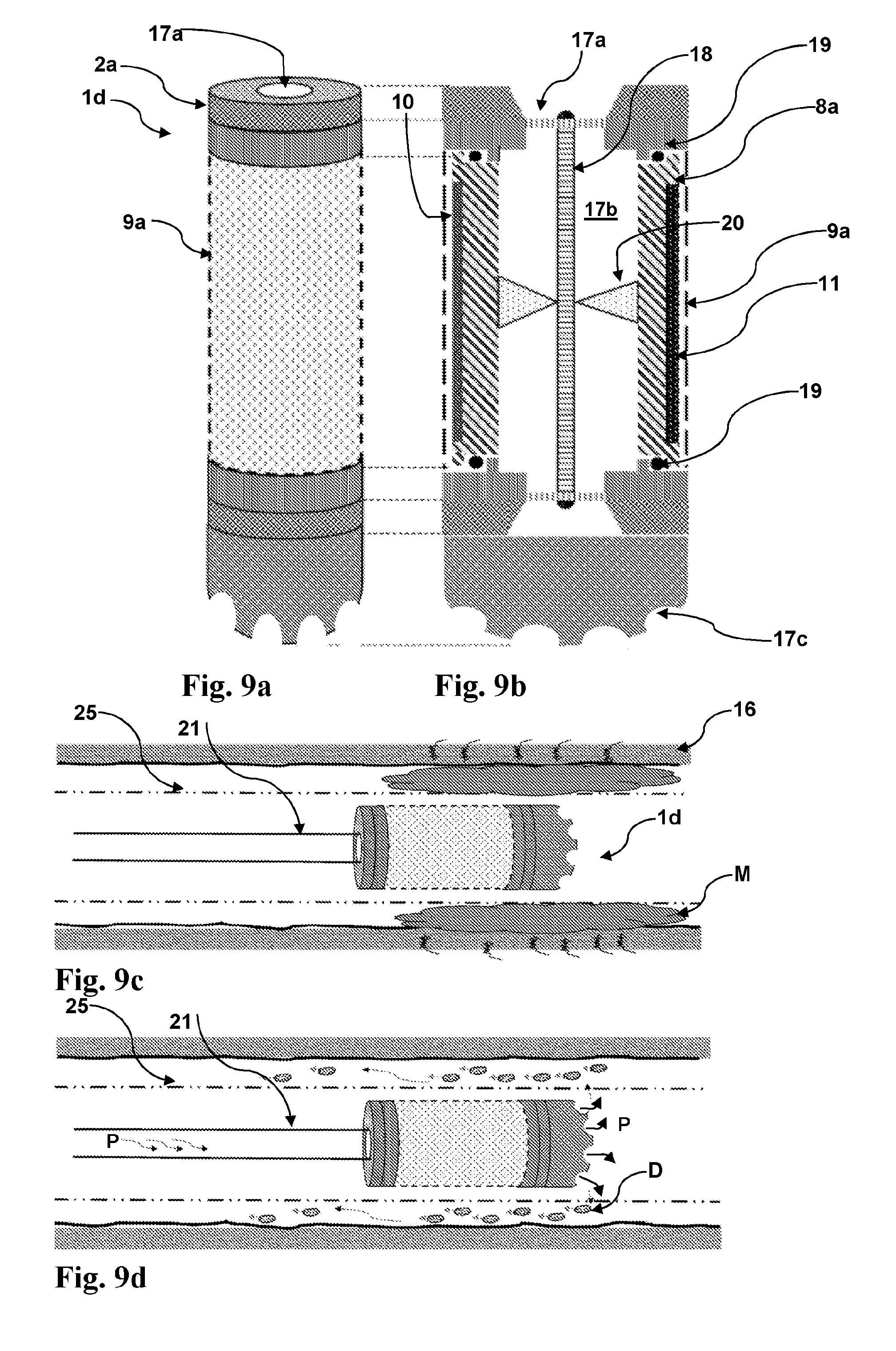
[0089] FIGS. 6a, 6b, 6c and 6d illustrate an alternative embodiment of the tool la, having another cylinder propulsion means. Here, the rotatable cylinder 8a (carrying the magnets 10, 11 as described above) comprises a fluid inlet port 17a and fluid outlet ports 17c, interconnected by an internal, through-going bore 17b. The cylinder 8b is supported by bearings 19 and connected to a turbine axle 18 via turbine blades 20. The turbine axle 18 is rotatably supported by the tool body, whereby the cylinder 8a will rotate on the tool body when a fluid is flowed through the internal bore 17b. The connection assembly 2a is configured for connection to a workstring, e.g. coiled tubing or drillpipe, whereby fluid may be pumped through the tool la to operate it. This mode of operation is illustrated in FIG. 6d, where a fluid P is pumped through the workstring 21, through the tool and out of the outlet nozzles 17c. The rotating cylinder 8a melts the bismuth-alloy sleeve 14 in a manner similar to the process described above, and molten bismuth alloy 14a will form a solidified seal on top of the cement C. This embodiment is useful when hydraulic flushing is required, in addition to the melting of the diamagnetic material.
[0090] FIGS. 7a and 7b illustrate another embodiment of the invented tool. The tool 1b is in principle of a similar design to the tool 1 described above, but comprises in addition a bismuth-alloy sleeve 14 arranged on the outer surface of the non-magnetic housing 9. The tool may be run on e.g. wireline 22. This embodiment is useful when performing for example plug-and-abandon operations in a wellbore. In operation, the rotating cylinder 8 heats the sleeve 14 material as described above, whereby molten material 14a accumulates on a plug foundation 23 to form a plug of solidified material 14b. The molten material may also flow through holes 24 in the casing and into the annulus between the casing 13 and the formation 16, and there settle and solidify on the annular cement A, whereby a full cross-sectional wellbore plug is generated. Although not illustrated, the tool 1b may be furnished with squeezing means, whereby bismuth alloy is forced into the annulus while in the molten state. It should be understood that the tool 1b may use other cylinder propulsion means than an electric motor; for example the turbine configuration described above with reference to FIGS. 6a-d.
[0091] FIGS. 8a and 8b illustrate a further embodiment of the invented tool. The tool 1c comprises magnetic field generator comprising a rotatable cylinder 8b having first and second magnets 10, 11 attached at regular intervals on the cylinder underside (see FIG. 8b). The tool the housing 9a is made of a material with suitable electrical conductivity, such as steel, whereby the housing 9a is heated when the cylinder is rotated and effectively constitutes a "heat cap". The selection of the housing 9a material and wall thickness, as well as cylinder rotational speed, is determined based on the desirable temperature to be achieved. Although not illustrated, it should be understood that the cylinder-magnet configuration described above with reference to FIGS. 2 to 7d, may also be furnished with a housing similar to the housing 9a. When the invented tool is used as a heater per se in this fashion, it may be used to heat selected locations in a flowline or pipe, for example where obstructive substances have formed. This is illustrated in FIGS. 8c and 8d, where the tool 1c has been conveyed (e.g. on wireline 22) to a location in a production tubing 12 where the obstructive materials M (e.g. wax, asphaltenes) are heated and thus melt and/dissolve into smaller, manageable particles D. Although not illustrated, it should be understood that the tool lc may be furnished with a bismuth-alloy sleeve 14, corresponding to the illustration of FIG. 7a, and thus be used to melt the bismuth alloy by controlling the time-varying magnetic field as described above.
[0092] FIGS. 9a and 9b show another embodiment of the tool 1d, which is similar to the embodiment described above with reference to FIGS. 6a-c, but where a housing 9a of a material with diamagnetic properties has been added. The tool 1d thus works similarly to the tool lc described above, as a heater per se. This tool 1d may be used to stimulate wells or in general generate heat where it may be needed in the wellbore, and advantageously connected to a workstring 21 (e.g. drillstring or coiled tubing), as shown in FIG. 9c. The tool can advantageously be operated in conjunction with hydraulic fluid treatment processes. FIGS. 9c and 9d illustrate such process, in which obstructive material M between a slotted liner 25 and a formation 16 is heated and dissolved, and the smaller particles M are flushed out in the annulus by the motive fluid P which is pumped through the workstring 21. The motive fluid may comprise inhibitors and/or dissolving agents.
[0093] FIG. 10 illustrates another embodiment and use of the invented tool. Here, the tool 1e has similar features and function as the tools 1, 1a, 1b, inasmuch as it comprises a magnetic field generator (e.g. a rotatable cylinder 8, 8a or 8b FIG. 10 showing a rotatable cylinder 8b) and an (optional) non-magnetic housing 9. It should be understood that this embodiment may use any of the magnetic field generators described above.
[0094] However, while the main gist of the embodiments described above is to generate heat by inducing eddy currents in diamagnetic materials, either to melt eutectic alloys (such as a bismuth alloy) or to melt and/or dissolve well obstructions (such as was or asphaltenes), the tool 1e utilizes the alternating magnetic field and the resulting eddy current in adjacent materials for detecting changes in such materials.
[0095] As FIG. 10 indicates, the rotating cylinder 8b (with the alternating magnets) generates an alternating magnetic field that penetrates the steel walls and generates eddy currents in the adjacent pipes, tubulars and/or cement. A sensor 27 (which is connected to the control module 3) is configured to measure the rotational moments of the rotating cylinder, or measure the electrical current in the coil array, and thus provide a measure of the energy loss due to any conductive material in the magnetic field. The tool 1e may thus be used for e.g. detecting regions of reduced casing 13 wall thickness, and for verifying cement in the annulus 26 and/or verifying bonding between annulus cement and the casing. Adding granules or fibers of conductive materials in the cement will enhance the detection capabilities.
[0096] Although the invention has been described with reference to bismuth alloys, it should be understood that the invention is equally applicable for eutectic material having similar electrically conducting properties as bismuth.
[0097] The skilled person, having knowledge of well properties such as temperatures and pressures, will select an alloy having suitable properties (e.g. sufficiently high melting temperature) for the applicable well. The skilled person will also have the knowledge to design and operate the invented tool with the magnetic field strength sufficient for the applicable use.
[0098] Although the invention has been described with reference to a rotating member in the is shape of a cylinder, it should be understood that other shapes may be equally applicable. Such shapes may, for example, be conical, frusto-conical or spherical.
[0099] Although the invention has been described with reference to a subterranean wellbores for production of hydrocarbons, it should be understood that the invention is equally applicable to plugs and seals in other tubulars, for example tubulars for water or other fluids.
* * * * *
D00000
D00001
D00002
D00003
D00004
D00005
D00006
D00007
XML
uspto.report is an independent third-party trademark research tool that is not affiliated, endorsed, or sponsored by the United States Patent and Trademark Office (USPTO) or any other governmental organization. The information provided by uspto.report is based on publicly available data at the time of writing and is intended for informational purposes only.
While we strive to provide accurate and up-to-date information, we do not guarantee the accuracy, completeness, reliability, or suitability of the information displayed on this site. The use of this site is at your own risk. Any reliance you place on such information is therefore strictly at your own risk.
All official trademark data, including owner information, should be verified by visiting the official USPTO website at www.uspto.gov. This site is not intended to replace professional legal advice and should not be used as a substitute for consulting with a legal professional who is knowledgeable about trademark law.