Wand For A Blind Assembly
Chua; Shih Yang
U.S. patent application number 16/311270 was filed with the patent office on 2019-06-27 for wand for a blind assembly. The applicant listed for this patent is Rollease Acmeda, Inc.. Invention is credited to Shih Yang Chua.
| Application Number | 20190195014 16/311270 |
| Document ID | / |
| Family ID | 60783586 |
| Filed Date | 2019-06-27 |

| United States Patent Application | 20190195014 |
| Kind Code | A1 |
| Chua; Shih Yang | June 27, 2019 |
WAND FOR A BLIND ASSEMBLY
Abstract
A wand for a blind assembly comprising (a) an elongated member, (b) a rotatable member located at or adjacent one end thereof, (c) guide member located at or adjacent another end thereof; and (d) a cord having a loop, wherein the loop passes from a position remote from the rotating member, engages the rotating member, passes about the guide member and returns to the remote position after reengagement of the rotating member, wherein the loop adjacent to or within the elongated member is retained between the rotating member and the guide to restrict movement of the loop perpendicularly of the elongated member, and wherein the loop remote from the rotating member is adapted to engage and rotate a drive member of a blind assembly.
| Inventors: | Chua; Shih Yang; (Sunshine West, Victoria, AU) | ||||||||||
| Applicant: |
|
||||||||||
|---|---|---|---|---|---|---|---|---|---|---|---|
| Family ID: | 60783586 | ||||||||||
| Appl. No.: | 16/311270 | ||||||||||
| Filed: | June 6, 2017 | ||||||||||
| PCT Filed: | June 6, 2017 | ||||||||||
| PCT NO: | PCT/AU2017/050558 | ||||||||||
| 371 Date: | December 19, 2018 |
| Current U.S. Class: | 1/1 |
| Current CPC Class: | E06B 2009/785 20130101; F16H 7/08 20130101; E06B 9/42 20130101; E06B 9/78 20130101; E06B 9/326 20130101; F16H 2007/0895 20130101; F16H 2007/0806 20130101; F16H 2007/0891 20130101; F16H 2007/0872 20130101 |
| International Class: | E06B 9/78 20060101 E06B009/78; F16H 7/08 20060101 F16H007/08 |
Foreign Application Data
| Date | Code | Application Number |
|---|---|---|
| Jun 21, 2016 | AU | 2016902418 |
Claims
1. A wand for a blind assembly comprising: (a) an elongated member, (b) a rotatable member located at or adjacent one end thereof. (c) a guide member located at or adjacent another end thereof; and (d) a cord having a loop, wherein the loop passes from a position remote from the rotating member, engages the rotating member, passes about the guide member and returns to the remote position after reengagement of the rotating member, wherein the loop adjacent to or within the elongated member is retained between the rotating member and the guide to restrict movement of the loop perpendicularly of the elongated member, and wherein the loop remote from the rotating member is adapted to engage and rotate a drive member of a blind assembly.
2. The wand of claim 1 wherein the rotatable member is a wheel, mounted for rotation in or on the elongated member.
3. The wand of claim 2 wherein the wheel has a plurality of positions to selectively retain the cord.
4. The wand of claim 2 wherein the cord is beaded and at least one of the beads is located at one of the positions which position comprises a depression.
5. The wand of claim 1 wherein the elongated member is substantially tubular and the cord is at least partially located within the elongated member.
6. The wand of claim 1 wherein the guide member comprises a guide pathway to receive at least part of the cord and a biasing member to bias the guide pathway in a direction away from the rotatable member to cause the cord passing therebetween to be under tension.
7. The wand of claim 3 wherein the cord is beaded and at least one of the beads is located at one of the positions which position comprises a depression.
8. The wand of claim 2 wherein the elongated member is substantially tubular and the cord is at least partially located within the elongated member.
9. The wand of claim 3 wherein the elongated member is substantially tubular and the cord is at least partially located within the elongated member.
10. The wand of claim 4 wherein the elongated member is substantially tubular and the cord is at least partially located within the elongated member.
11. The wand of claim 2 wherein the guide member comprises a guide pathway to receive at least part of the cord and a biasing member to bias the guide pathway in a direction away from the rotatable member to cause the cord passing therebetween to be under tension.
12. The wand of claim 3 wherein the guide member comprises a guide pathway to receive at least part of the cord and a biasing member to bias the guide pathway in a direction away from the rotatable member to cause the cord passing therebetween to be under tension.
13. The wand of claim 4 wherein the guide member comprises a guide pathway to receive at least part of the cord and a biasing member to bias the guide pathway in a direction away from the rotatable member to cause the cord passing therebetween to be under tension.
14. The wand of claim 5 wherein the guide member comprises a guide pathway to receive at least part of the cord and a biasing member to bias the guide pathway in a direction away from the rotatable member to cause the cord passing therebetween to be under tension.
Description
FIELD
[0001] The present invention relates generally to a wand for use with a blind assembly. More particularly the invention relates to a wand which may be retrofitted to an existing blind assembly.
BACKGROUND
[0002] In this specification where a document, act or item of knowledge is referred to or discussed, this reference is not an admission that the document, act or item of knowledge or any combination thereof was at the priority date, publicly available, known to the public, part of the common general knowledge; or known to be relevant to an attempt to solve any problem with which this specification is concerned.
[0003] A blind assembly has a blind component (or fitting) that is rotatable to, for example, extend and retract a window covering such as a window blind. Such assemblies typically have a drive mechanism that is rotatable about a spindle, and engages a cord (for example a beaded cord or chain). Operation of the cord causes the drive mechanism to rotate about the spindle. For example, the cord may be pulled in one direction to rotate the fitting in a blind extending direction and the cord may be pulled in an opposite direction to rotate the fitting in a blind retraction direction.
[0004] In cord operated blind assemblies, the cord is usually in the form of a loop which hangs approximately vertically from the assembly to allow easy operation by the user pulling on the cord. However, the problem with a hanging cord loop is that it presents a safety risk especially to small child. In particular, the loop may become entangled around the neck of a child and present a strangulation risk.
[0005] A number of solutions have been proposed to mitigate against this risk. In particular, devices known as wands have been proposed and sold which comprise a device to substantially enclose a cord loop. This minimizes the risks of the loop being accessed to form an expanded loop which may pose the child safety risk.
[0006] A typical wand of this type is described in WO201113402. As described this wand includes a rigid elongated member which has a pair of wheels, one at either end and around which the cord is looped. The relative sizes of the cord loop and the elongated member is selected such that movement of the loop perpendicular to the longitudinal axis of the elongated member is limited. One wheel at one end of the elongated member is rigidly attached to constitute the drive mechanism for the spindle.
[0007] Accordingly such wands require integral rigid fixing to the blind assembly. As such these wands are part of the original blind assembly upon installation or if attempted to be fit retrospectively require the blind assembly to be disassembled and reinstalled. This adds to the cost of the blind assembly and its installation.
[0008] The present invention seeks to provide a simple means to incorporate a wand type safety device into an existing installed blind assembly though of course, if desired, it can be incorporated in the initial blind assembly.
SUMMARY
[0009] According to a first aspect of the invention, there is provided a wand for a blind assembly comprising:
[0010] (a) an elongated member,
[0011] (b) a rotatable member located at or adjacent one end thereof.
[0012] (c) a guide member located at or adjacent another end thereof; and
[0013] (d) a cord having a loop,
[0014] wherein the loop passes from a position remote from the rotating member, engages the rotating member, passes about the guide member and returns to the remote position after reengagement of the rotating member,
[0015] wherein the loop adjacent to or within the elongated member is retained between the rotating member and the guide to restrict movement of the loop perpendicularly of the elongated member, and
[0016] wherein the loop remote from the rotating member is adapted to engage and rotate a drive member of a blind assembly.
[0017] Typically, the rotatable member is a wheel, mounted for rotation in or on the elongated member. The wheel will usually have a plurality of positions to selectively retain the cord in position. So if the cord is beaded, at least one of the beads will be located in a depression at one of the wheel positions.
[0018] Typically, the elongated member is substantially tubular and the cord is at least partially located within the elongated member.
[0019] Typically, the guide member comprises a guide pathway to receive at least part of the cord and a biasing member to bias the guide pathway in a direction away from the rotatable member to cause the cord passing therebetween to be under tension. The guide pathway may be defined by a surface of a cylindrical member which is urged in the desired direction by a mounted spring device.
[0020] This lack of perpendicular slack in the cord loop improves safety by not permitting an undesirable loop to form which may be a hazard to children.
[0021] If the cord is beaded, rotation of the rotatable member will cause the beads and depressions in the rotatable member to engage, such that the beaded coil on one side of the rotatable member will be pulled in the direction of the biasing member, and the coil on the other side of the rotatable member will equally be pulled away from the direction of the biasing member. This feature also improves the safety of the assembly as the amount of cord in the guide member and the biasing member is kept consistent.
[0022] Additionally this arrangement may exhibit less operational nose due to the cord loop adjacent the elongated body being under tension.
[0023] Unlike conventional wands, the wand of the invention may be both installed when installing a new blind assembly or also be a retrofit to an existing blind system. This is possible by reason of not requiring an end of the elongated member to directly engage the drive member of the blind assembly. This means that it is possible to retrofit the wand on an existing blind assembly without having to replace the winder mechanism.
[0024] This means no special attachment device needs to be present. With the wand of the current invention, the cord loop outside the elongated member can be engaged about the drive member simply and easily. The chain wheel in the rotatable member limits the length of cord loop inside or adjacent the elongated member and restricts the movement of the cord perpendicular to the elongated member.
[0025] A detailed description of one or more embodiments of the invention is provided below, along with accompanying figures that illustrate by way of example the principles of the invention. While the invention is described in connection with such embodiments, it should be understood that the invention is not limited to any embodiment. On the contrary, the scope of the invention is limited only by the appended claims and the invention encompasses numerous alternatives, modifications and equivalents.
[0026] For the purpose of example, numerous specific details are set forth in the following description in order to provide a thorough understanding of the present invention. The present invention may be practiced according to the claims without some or all of these specific details. For the purposes of clarity, technical material that is known in the technical fields related to the invention has not been described in detail so that the present invention is not unnecessarily obscured.
[0027] For the purposes of providing a clear description of the present invention, terms such as "up", "down", "left" and "right" are used in the below descriptions. This terminology will be understood to be for illustrative purposes only, and does not limit the scope of the present invention.
BRIEF DESCRIPTION OF THE DRAWINGS
[0028] Various embodiments/aspects of the invention will now be described with reference to the following drawings in which,
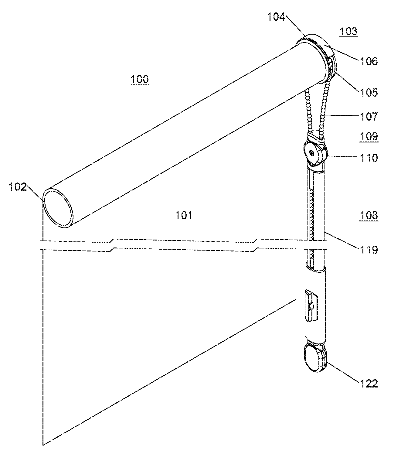
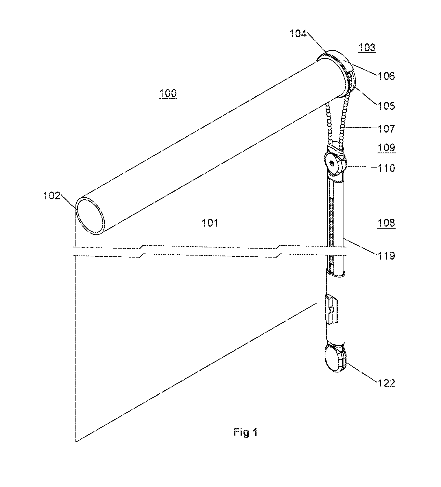
[0029] FIG. 1 depicts a perspective view of a blind assembly with a wand according to one aspect of the invention in the installed position.
[0030] FIG. 2 depicts front, side and perspective views (A, B and C) of a wand accordingly to an aspect of the invention.
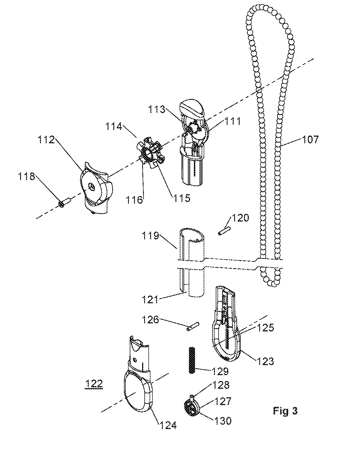
[0031] FIG. 3 depicts a perspective assembly view of the wand of FIG. 2.
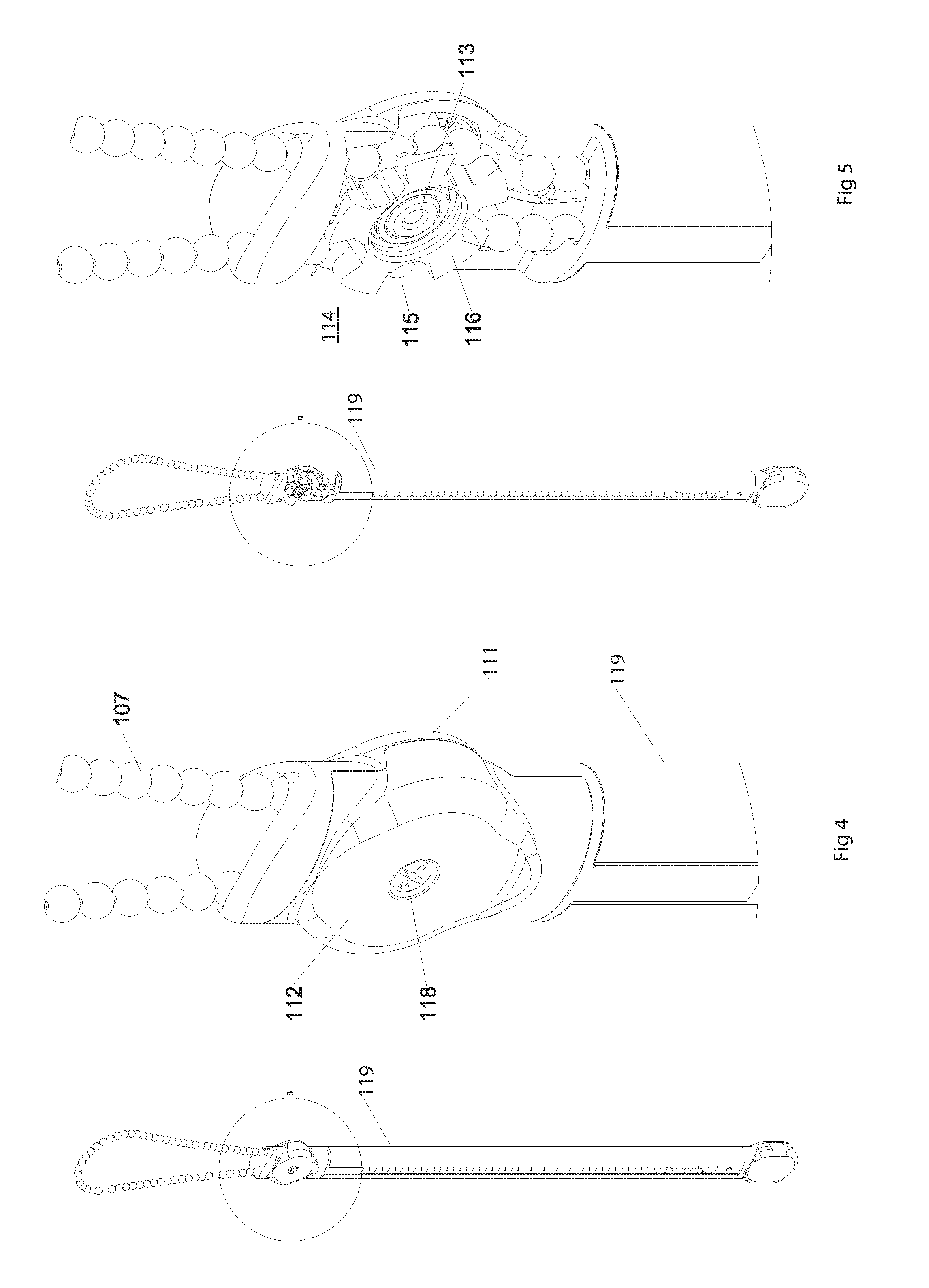
[0032] FIG. 4 is a perspective view and partial view B (circled) of the wand according to FIG. 2.
[0033] FIG. 5 is a perspective view and partial view D (circled) of the wand according to FIG. 2 in a partially disassembled form.
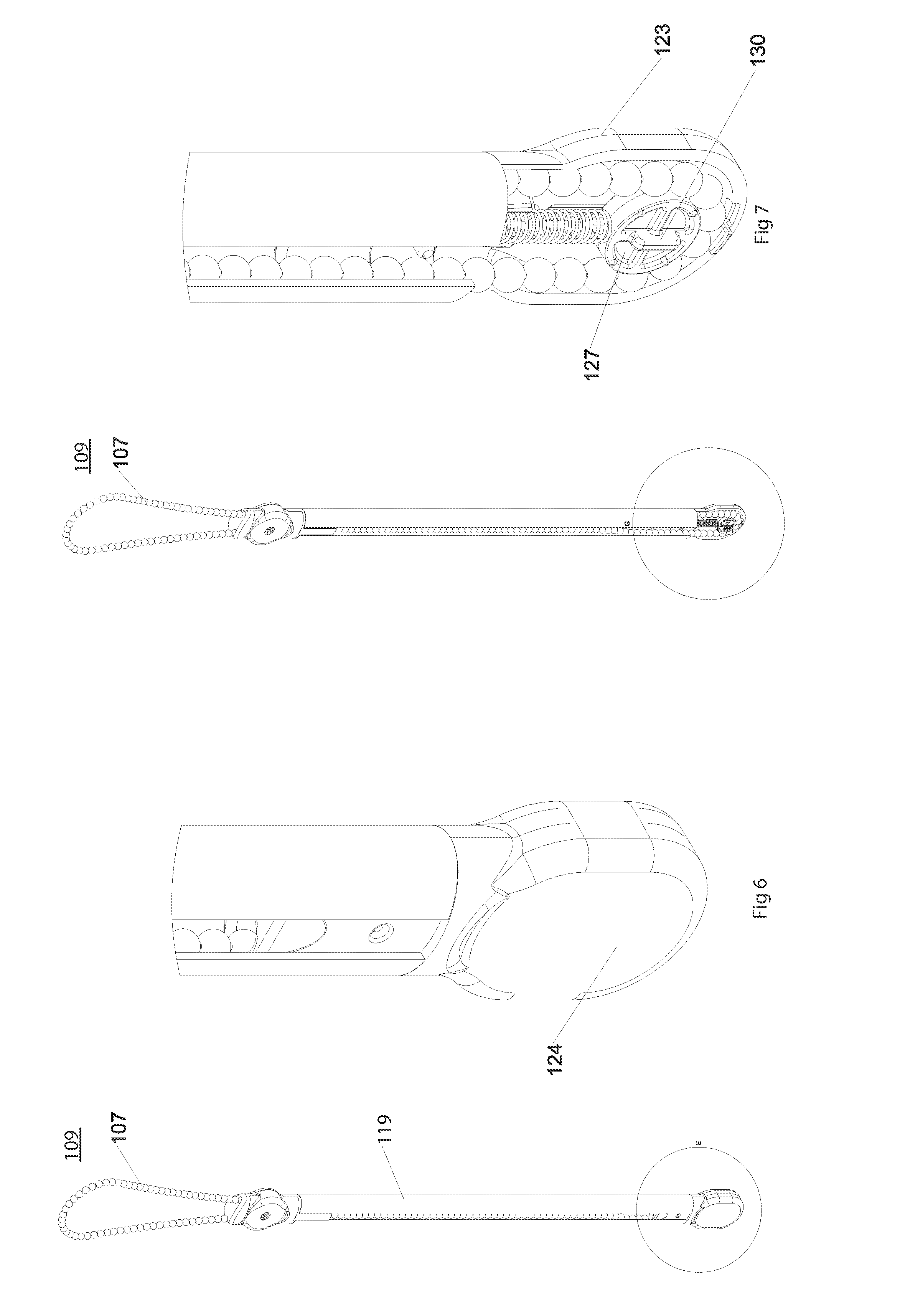
[0034] FIG. 6 is a perspective view and partial view E (circled) of the wand according to FIG. 2.
[0035] FIG. 7 is a perspective view and partial view G (circled) of the wand according to FIG. 2 in a partially disassembled form.
DETAILED DESCRIPTION
[0036] FIG. 1 depicts a blind assembly 100 comprising a blind 101 which is rolled onto a cylinder 102. Rotation of the cylinder 102 in different directions cause the blind 101 to either retract or extend. The cylinder 102 is engaged on a spindle (not shown) which is located at the right end of the cylinder 102. The drive member 103 extends from the spindle with a flange 104, a rotatable wheel 105 and a cover 106. A beaded cord 107 is located about wheel 105. Pulling on portion of the cord 107 causes the wheel 105 to rotate the drive member 103. This cause cylinder 102 to rotate and the blind to extend or retract.
[0037] The wand 108 has a beaded cord loop portion 109 which is located about wheel 105. The other end of this loop portion 109 enters a rotatable member 110. As shown in FIGS. 3, 4 and 5, the rotatable member 110 comprises a housing of two parts 111 and 112. Part housing 111 includes an axle mount 113. Axle mount 113 receives the wheel 114 and permits the wheel 114 to rotate freely thereabout. Wheel 114 (as more clearly shown in FIG. 5) has a number of regularly spaced radial openings 115 and arms 116 which together are able to retain beads 117. The other housing part 112 covers the wheel 114 and may be fastened to the axle mount 113 with screw 118.
[0038] Wheel 114 is located in one end of elongated tubular member 119 and fixed in position by screw 120. Elongated member 119 may be of any suitable length sufficient to enclose the beaded cord 107 over a sufficient length to assist prevention of the formation of a potentially dangerous loop. It is unnecessary that elongated member 119 be completely enclosed as shown in FIG. 2 and may have a longitudinal opening 121.
[0039] At the other end of elongated tubular member 119 is a guide member 122. As more particularly shown in FIGS. 2, 6 and 7 the guide member 122 comprises a housing of two parts 123 and 124. Part housings 123 and 124 includes matching linear slots 125. Located in these slots 125 when the part housings 123 and 124 are connected (via pin 126) is a cylinder member 127. Cylinder member 127 has corresponding arms 130 which when assembled located for sliding movement in linear slots 125.
[0040] Cylinder member 127 has a pin projection 128 extending in the axial direction of elongated tubular member 119. A spring 129 envelops the pin projection 128 at one end. The other end of the spring 129 sits in the parts housing 123 and 124.
[0041] As shown in FIGS. 5 and 7, cord 107 extends from the wheel 114 down both internal surfaces of the elongated tubular member 119 and about part of the circumferential surface of cylinder 127. Cylinder member 127 under the influence of spring 129 is urged away from the rotatable member 110 and places the cord 107 in tension between the rotatable member 110 and the cylindrical member 127.
[0042] Pulling on cord 107 in a blind-extending direction causes the wheel 114 of the rotatable member 110 to rotate. The rotation of wheel 114 engages openings 115 and arms 116 with beads 117 and therefore cord 107 on one side of the wheel 114 to pull that portion of the cord 107 in the direction of cylindrical member 127. The rotation of wheel 114 also causes the openings 115 and arms 116 on the opposite side of the wheel 114 to take up beads 117 and therefore the cord 107 from the direction of the cylindrical member 127.
[0043] In this arrangement, wheel 114 restricts the movement of the cord 107 in a direction perpendicular to the elongated tube 119. Therefore the risk of a loop of the cord 107 forming which would prevent a safety hazard to a child is minimized.
[0044] Modifications and improvements to the invention will be readily apparent to those skilled in the art. Such modifications and improvements are intended to be within the scope of this invention.
[0045] The word `comprising` and forms of the word `comprising` as used in this description and in the claims does not limit the invention claimed to exclude any variants or additions.
* * * * *
D00000
D00001
D00002
D00003
D00004
D00005
XML
uspto.report is an independent third-party trademark research tool that is not affiliated, endorsed, or sponsored by the United States Patent and Trademark Office (USPTO) or any other governmental organization. The information provided by uspto.report is based on publicly available data at the time of writing and is intended for informational purposes only.
While we strive to provide accurate and up-to-date information, we do not guarantee the accuracy, completeness, reliability, or suitability of the information displayed on this site. The use of this site is at your own risk. Any reliance you place on such information is therefore strictly at your own risk.
All official trademark data, including owner information, should be verified by visiting the official USPTO website at www.uspto.gov. This site is not intended to replace professional legal advice and should not be used as a substitute for consulting with a legal professional who is knowledgeable about trademark law.