Ballast Sweeping Installation For Picking Up And Distributing Ballast Located On A Track
LINTZ; Gerard
U.S. patent application number 16/301107 was filed with the patent office on 2019-06-27 for ballast sweeping installation for picking up and distributing ballast located on a track. The applicant listed for this patent is PLASSER & THEURER EXPORT VON BAHNBAUMASCHINEN GESELLSCHAFT M.B.H. Invention is credited to Gerard LINTZ.
| Application Number | 20190194877 16/301107 |
| Document ID | / |
| Family ID | 58579133 |
| Filed Date | 2019-06-27 |

| United States Patent Application | 20190194877 |
| Kind Code | A1 |
| LINTZ; Gerard | June 27, 2019 |
Ballast Sweeping Installation For Picking Up And Distributing Ballast Located On A Track
Abstract
A ballast sweeping installation for picking up and distributing ballast located on a track includes a sweeping brush rotatable about an axis of rotation, a ballast conveyor belt disposed ahead of the sweeping brush relative to a brush rotation direction, and a ballast guiding plate positioned between the sweeping brush and the ballast conveyor belt for passing the ballast on to the ballast conveyor belt. A length of the ballast conveyor belt delimited by two deflection ends is shorter than a length of the sweeping brush along the axis of rotation. Additionally, the ballast conveyor belt is configured to be displaceable in a transport direction relative to the sweeping brush by a drive. Thus, an optimal ballast distribution in tamping zones of the track is made possible.
| Inventors: | LINTZ; Gerard; (BENING-LES-SAINT-AVOLD, FR) | ||||||||||
| Applicant: |
|
||||||||||
|---|---|---|---|---|---|---|---|---|---|---|---|
| Family ID: | 58579133 | ||||||||||
| Appl. No.: | 16/301107 | ||||||||||
| Filed: | April 24, 2017 | ||||||||||
| PCT Filed: | April 24, 2017 | ||||||||||
| PCT NO: | PCT/EP2017/000504 | ||||||||||
| 371 Date: | November 13, 2018 |
| Current U.S. Class: | 1/1 |
| Current CPC Class: | E01B 27/026 20130101; E01B 2203/027 20130101 |
| International Class: | E01B 27/02 20060101 E01B027/02 |
Foreign Application Data
| Date | Code | Application Number |
|---|---|---|
| May 23, 2016 | AT | A 258/2016 |
Claims
1-5. (canceled)
6. A ballast sweeping installation for picking up and distributing ballast located on a track, the ballast sweeping installation comprising: a sweeping brush being rotatable about an axis of rotation in a brush rotation direction, said sweeping brush having length along said axis of rotation; a ballast conveyor belt disposed ahead of said sweeping brush relative to said brush rotation direction, said ballast conveyor belt having a transport direction extending parallel to said axis of rotation; said ballast conveyor belt having two deflection ends and having a length delimited by said two deflection ends being shorter than said length of said sweeping brush; a drive for displacing said ballast conveyor belt in said transport direction relative to said sweeping brush; and a ballast guiding plate positioned between said sweeping brush and said ballast conveyor belt for passing the ballast on to said ballast conveyor belt.
7. The ballast sweeping installation according to claim 6, wherein said drive is configured for selectively reversing a displacement direction of said ballast conveyor belt extending parallel to said axis of rotation.
8. The ballast sweeping installation according to claim 6, wherein said length of said ballast conveyor belt corresponds approximately to a gauge of the track.
9. The ballast sweeping installation according to claim 6, which further comprises a rotation drive configured for reversing said transport direction of said ballast conveyor belt.
10. The ballast sweeping installation according to claim 6, which further comprises two cover plates disposed underneath said ballast conveyor belt for avoiding any ballast discharge upon rails of the track, said two cover plates being spaced apart from one another in said transport direction at a distance corresponding to a gauge of the track.
Description
[0001] The invention relates to a ballast sweeping installation for picking up and distributing ballast located on a track, consisting of a sweeping brush rotatable about an axis of rotation, a ballast conveyor belt arranged in front of the same with regard to a brush rotation direction and having a transport direction extending parallel to the axis of rotation, and with a ballast guiding plate positioned between the sweeping brush and ballast conveyor belt for passing the ballast on to the ballast conveyor belt.
[0002] Ballast sweeping installations of this kind are often used in connection with a ballast plough and are known, for instance, from DE 911 02 31 U1 or EP 2 250 318. In this, excess ballast is swept from the track and fed to a conveyor belt for discharge in the shoulder area of the track.
[0003] Also known, according to WO 2013/189564, is a ballast plough having a ballast silo for intermediate storage of large quantities of ballast. If the ballast silo is full, the same can be discharged into the shoulder area of the track by means of a transversely displaceable conveyor belt.
[0004] It is the object of the present invention to provide a ballast sweeping installation of the type mentioned at the beginning with which an improved ballast distribution is possible.
[0005] According to the invention, this object is achieved with a ballast sweeping installation of the specified kind in that a length of the ballast conveyor belt delimited by two deflection ends is designed to be shorter than a length of the sweeping brush extending in the axis of rotation, and that the ballast conveyor belt is designed to be displaceable in the transport direction by means of a drive.
[0006] With this special design of the ballast conveyor belt, it is now possible in an advantageous manner to discharge excess ballast, picked up by the sweeping brush, in a targeted manner into the tamping zones of the track as needed in order to ultimately enable a qualitatively uniform tamping. Consequently, a heretofore customary disposal of the excess ballast into the shoulder area and a resulting uneconomical ballast accumulation becomes unnecessary.
[0007] Additional advantages of the invention become apparent from the dependent claims and the drawing description.
[0008] The invention will be described in more detail below with reference to an embodiment represented in the drawing in which
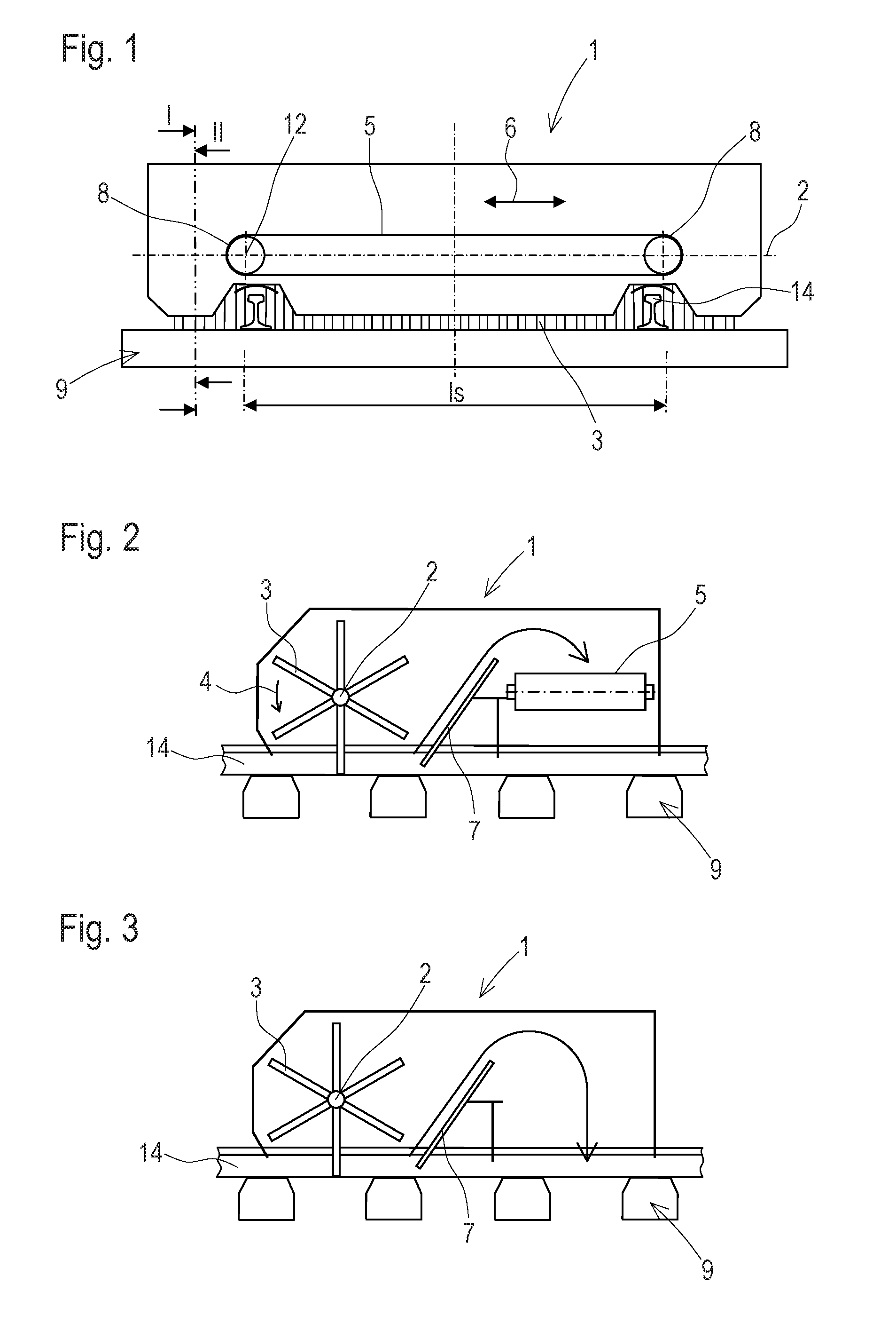
[0009] FIG. 1 shows a view of a ballast sweeping installation in a longitudinal direction of the track,
[0010] FIGS. 2 and 3 each show a cross-section of the ballast sweeping installation,
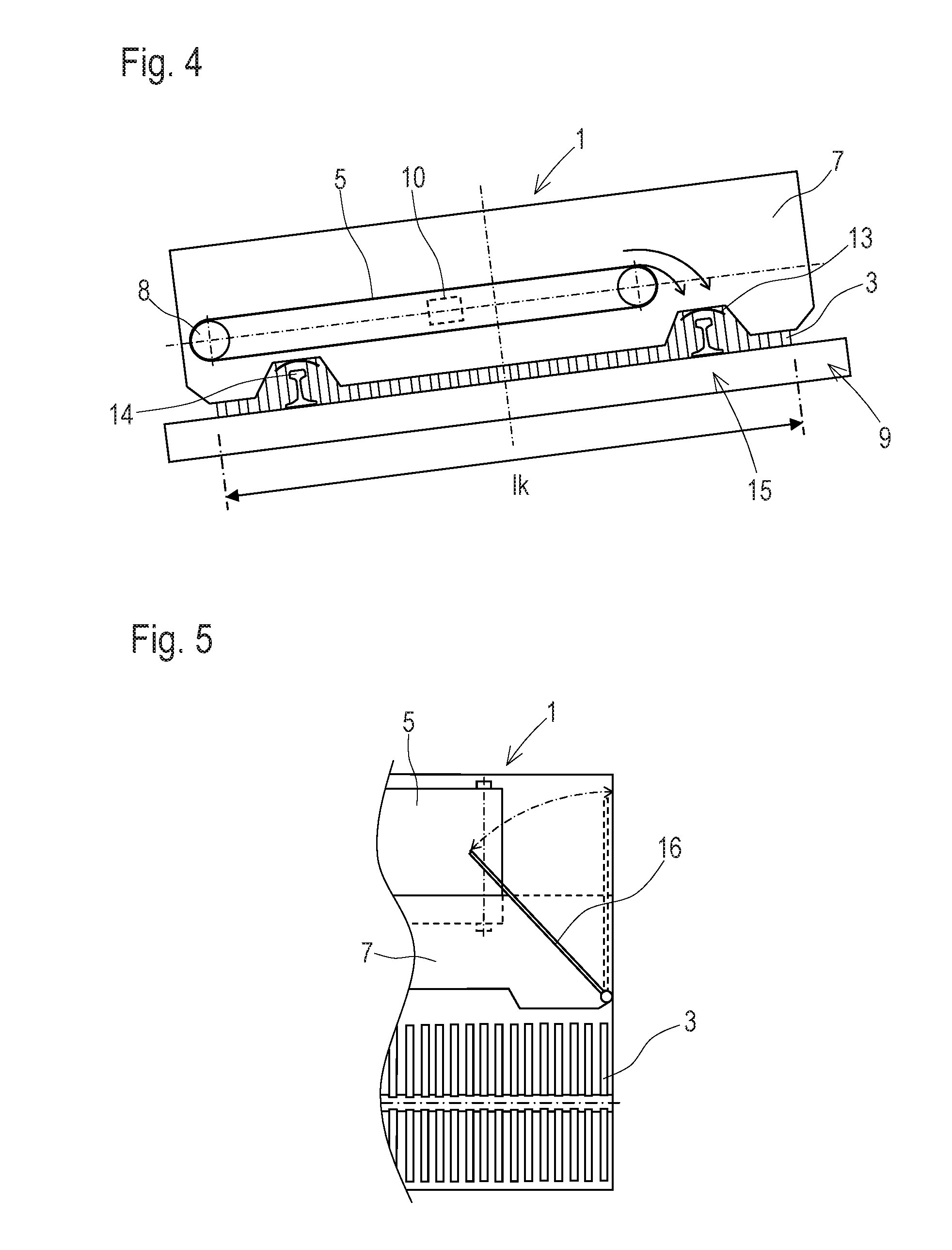
[0011] FIG. 4 shows a maximum displacement of a ballast conveyor belt, and
[0012] FIG. 5 shows a simplified top view of an alternative embodiment of the ballast sweeping installation.
[0013] A ballast sweeping installation 1, represented in FIGS. 1 to 5, for picking up and distributing ballast located on a track consists of a sweeping brush 3 rotatable about an axis of rotation 2, and a ballast conveyor belt 5 arranged ahead of the same with regard to a brush rotation direction 4 and having a transport direction 6 extending parallel to the axis of rotation 2. Located between the sweeping brush 3 and the ballast conveyor belt 5 is a ballast guiding plate 7, arranged inclined, for passing the ballast captured by the sweeping brush 3 on to the ballast conveyor belt 5.
[0014] A length l.sub.S of the ballast conveyor belt 5 delimited by two deflection ends 8 is designed to be shorter than a length l.sub.K of the sweeping brush 3 extending in the axis of rotation 2. Preferably, the length l.sub.S of the ballast conveyor belt 5 is designed to correspond approximately to a gauge of a track 9 to be swept off.
[0015] The ballast conveyor belt 5 is designed to be displaceable by means of a drive 10 in the transport direction 6 relative to the sweeping brush 3 and parallel to the axis of rotation 2 in both directions. Preferably, the displacement path is dimensioned in such a way that each deflection end 8 is movable in each case from the position visible in FIG. 1 to a closer positioned adjoining end of the sweeping brush 3. With the aid of a reversible rotation drive 12, the ballast can be shifted selectively to one or the other deflection end 8 by reversing the transport direction 6.
[0016] Arranged underneath the ballast conveyor belt 5 are two cover plates 13--spaced from one another in the transport direction 6 at a distance corresponding to the gauge of the track 9--for avoiding any ballast discharge upon rails 14 of the track 9. The tamping zones 15 which are essential for a tamping of the track 9 are located adjoining both longitudinal sides of the rail 14.
[0017] Due to the displaceability of the ballast conveyor belt 5, it is possible, for example--in the case of an adjacent track to the left as seen in the track direction in FIG. 4--by maximum displacement towards the neighbouring track to discharge ballast collected by the sweeping brush 3 into the tamping zones 15 of the rail 14 spaced farther from the neighbouring track. This is advantageous particularly if, in the case of a transverse track inclination (see FIG. 4), said rail 14 is positioned higher. In this situation there is often the problem that, in the region of the higher positioned rail, too little ballast is present for an optimal tamping.
[0018] However, it is advantageously also possible in the central basic position of the ballast conveyor belt 5 visible in FIG. 1 to discharge ballast as needed into the tamping zone of the left or right rail 14 by rapid reversal of the transport direction 6.
[0019] As can be seen in FIG. 5, as alternative auxiliary equipment a deflection plate 16 is provided in each case at an end region of the ballast guiding plate 7. Said deflection plate 16 is connected to the ballast guiding plate 7 and pivotable about a pivot axis extending perpendicularly to a plane of the ballast guiding plate 7 from a position represented in a dashed line into a deflection position represented in a full line. In this position, the ballast is deflected for deposit to the ballast conveyor belt 5 if the latter is situated in the maximum left-hand position shown in FIG. 4.
* * * * *
D00000
D00001
D00002
XML
uspto.report is an independent third-party trademark research tool that is not affiliated, endorsed, or sponsored by the United States Patent and Trademark Office (USPTO) or any other governmental organization. The information provided by uspto.report is based on publicly available data at the time of writing and is intended for informational purposes only.
While we strive to provide accurate and up-to-date information, we do not guarantee the accuracy, completeness, reliability, or suitability of the information displayed on this site. The use of this site is at your own risk. Any reliance you place on such information is therefore strictly at your own risk.
All official trademark data, including owner information, should be verified by visiting the official USPTO website at www.uspto.gov. This site is not intended to replace professional legal advice and should not be used as a substitute for consulting with a legal professional who is knowledgeable about trademark law.