Sheet Conveying Apparatus, Image Reading Apparatus And Image Forming Apparatus
Yamaguchi; Takuya
U.S. patent application number 16/223646 was filed with the patent office on 2019-06-27 for sheet conveying apparatus, image reading apparatus and image forming apparatus. The applicant listed for this patent is CANON KABUSHIKI KAISHA. Invention is credited to Takuya Yamaguchi.
| Application Number | 20190193970 16/223646 |
| Document ID | / |
| Family ID | 66949948 |
| Filed Date | 2019-06-27 |


View All Diagrams
| United States Patent Application | 20190193970 |
| Kind Code | A1 |
| Yamaguchi; Takuya | June 27, 2019 |
SHEET CONVEYING APPARATUS, IMAGE READING APPARATUS AND IMAGE FORMING APPARATUS
Abstract
Disclosed is a sheet conveying apparatus including an opening and closing member rotatable; a rotating member provided on the opening and closing member and which is rotatable by a sheet; and an assist member which is provided on the opening and closing member, and is at a first position when the opening and closing member is at the closed position, and is at a second position when the opening and closing member is at the open position, wherein the assist member urges the rotating member toward the opening and closing member side when the assist member is at the second position.
| Inventors: | Yamaguchi; Takuya; (Nagareyama-shi, JP) | ||||||||||
| Applicant: |
|
||||||||||
|---|---|---|---|---|---|---|---|---|---|---|---|
| Family ID: | 66949948 | ||||||||||
| Appl. No.: | 16/223646 | ||||||||||
| Filed: | December 18, 2018 |
| Current U.S. Class: | 1/1 |
| Current CPC Class: | B65H 2402/441 20130101; B65H 3/06 20130101; B65H 2511/51 20130101; B65H 3/0684 20130101; B65H 2553/81 20130101; B65H 2553/612 20130101; B65H 2801/06 20130101; B65H 2601/11 20130101; B65H 2511/528 20130101; B65H 5/062 20130101; B65H 7/04 20130101; B65H 1/14 20130101; B65H 2511/515 20130101 |
| International Class: | B65H 7/04 20060101 B65H007/04; B65H 3/06 20060101 B65H003/06; B65H 5/06 20060101 B65H005/06 |
Foreign Application Data
| Date | Code | Application Number |
|---|---|---|
| Dec 25, 2017 | JP | 2017-247537 |
Claims
1. An apparatus comprising: an opening and closing member configured to be rotatable and configured to be located at a closed position and an open position; a rotating member rotatablely provided on the opening and closing member and configured to be rotatable by a sheet; and an assist member provided on the opening and closing member, the assist member being configured to be located at a first position when the opening and closing member is located at the closed position and configured to be located at a second position when the opening and closing member is located at the open position, wherein the assist member is configured to be displaceable from the first position to the second position by a weight of the assist member with a rotation of the opening and closing member from the close position toward the open position, wherein the assist member is configured to urge the rotating member toward a side of the opening and closing member when the assist member is located at the second position.
2. The apparatus according to claim 1, wherein the assist member is provided on the opening and closing member such that the assist member is rotatable, the assist member being configured to be separated from the rotating member when the assist member is located at the first position, the assist member being configured to rotate from the first position to the second position by the weight of the assist member according to a movement of the opening and closing member from the closed position to the open position so that the assist member presses the rotating member and urges the rotating member toward the side of the opening and closing member.
3. The apparatus according to claim 1, wherein a center of rotation of the rotating member is disposed at a lower portion of the opening and closing member when the opening and closing member is located at the closed position.
4. The apparatus according to claim 1, wherein a direction of a rotational moment by the weight of the assist member is switched while the opening and closing member is moved from the closed position to the open position.
5. The apparatus according to claim 1, wherein the opening and closing portion comprises an accommodating portion configured to accommodate the rotating member.
6. The apparatus according to claim 1, wherein a conveying unit is located in a vicinity of the rotating member, the conveying unit having a conveying member which conveys a sheet, the conveying unit being configured to be detachably attachable to the opening and closing member.
7. The apparatus according to claim 1, wherein an abutting portion of the assist member, which presses the rotating member is of a circular arc shape.
8. The apparatus according to claim 1, wherein, a center of gravity of the rotating member is disposed in a vicinity of a center of rotation of the rotating member when the opening and closing member is located at the closed position.
9. The apparatus according to claim 2, wherein a center of gravity of the assist member is disposed in a vicinity of a center of rotation of the assist member when the opening and closing member is located at the closed position.
10. The apparatus according to claim 2, wherein a center of gravity of the assist member is moved from one side of a center of rotation of the assist member to the other side of the center of the rotation of the assist member in a horizontal direction while the opening and closing member is moved from the closed position to the open position.
11. The apparatus according to claim 2, wherein the assist member rotates in the direction opposite to that of the rotational member to urge the rotational member toward the side of the opening and closing member when the opening and closing member is moved from the closed position to the open position.
12. The apparatus according to claim 2, wherein the assist member rotates in the same direction as that of the rotational member to urge the rotational member toward the side of the opening and closing member when the opening and closing member is moved from the closed position to the open position.
13. The apparatus according to claim 1, further comprising a sheet supporting portion configured to support the sheet to be conveyed; and a sensor configured detect a rotation of the rotating member, the rotating member is rotated by the sheet on the sheet supporting portion.
14. The apparatus according to claim 13, wherein a rotation center of the rotating member is above the sheet supporting portion in a state that the opening and closing member is located at the closed position.
15. The apparatus according to claim 1, wherein the assist member is configured not to act on the rotating member when the assist member is located at the first position.
16. An image reading apparatus which reads an image of a sheet, comprising: an opening and closing member configured to be rotatable and configured to be located at a closed position and an open position; a rotating member rotatablely provided on the opening and closing member and configured to be rotatable by the sheet; an assist member provided on the opening and closing member, the assist member being configured to be located at a first position when the opening and closing member is located at the closed position and configured to be located at a second position when the opening and closing member is located at the open position, wherein the assist member is configured to be displaceable from the first position to the second position by a weight of the assist member with a rotation of the opening and closing member from the close position toward the open position; and a reading portion configured to read an image formed on a sheet, wherein the assist member is configured to urge the rotating member toward a side of the opening and closing member when the assist member is located at the second position.
17. An image forming apparatus which forms an image on a sheet, comprising: an opening and closing member configured to be rotatable and configured to be located at a closed position and an open position; a rotating member rotatablely provided on the opening and closing member and configured to be rotatable by a sheet; an assist member provided on the opening and closing member, the assist member being configured to be located at a first position when the opening and closing member is located at the closed position and configured to be located at a second position when the opening and closing member is located at the open position, wherein the assist member is configured to be displaceable from the first position to the second position by a weight of the assist member with a rotation of the opening and closing member from the close position toward the open position; and an image forming portion configured to form an image on a sheet, wherein the assist member is configured to urge the rotating member toward a side of the opening and closing member when the assist member is located at the second position.
Description
BACKGROUND OF THE INVENTION
Field of the Invention
[0001] The present invention relates to an apparatus having a rotating member for detecting the presence or absence of a sheet.
Description of the Related Art
[0002] An image forming apparatus that performs recording on a sheet using an electro-photographic method, such as an electro-photographic copying machine, has an image reading apparatus having an image reading portion, an image forming portion that forms a toner image on an image bearing member such as a photosensitive drum, and a sheet conveying apparatus for conveying a sheet from a feeding tray or the like.
[0003] Such a sheet conveying apparatus has a mechanism for detecting whether sheets are stacked on the sheet stacking tray. Such sheet detection mechanism has, for example, a detection flag rotatable by its own weight provided in the sheet conveyance path. When a sheet is set on the sheet stacking tray, the sheet detection flag is pushed by the leading end of the sheet and is rotated to release light shielding of the photo interrupter to recognize the presence of the sheet. Conversely, when there are no sheets, the sheet detection flag blocks the light of the photo interrupter to recognize the sheet absence state. In this way it is possible to determine the presence or absence of a sheet.
[0004] Further, in the sheet conveying apparatus as described above, when a situation occurs in which a sheet is jammed during conveyance, the sheet conveying path can be exposed so that the jammed sheet can be removed. For this purpose, the sheet conveying path is configured by the apparatus main body and an opening and closing member rotatable with respect to the apparatus main body. When the sheet is jammed, the jammed sheet can be removed by exposing the conveying path by rotating the opening and closing member.
[0005] In the above configuration, when the opening and closing member is rotated to expose the sheet conveying path, the sheet detection flag rotates by its own weight and retracts to come into contact with the surface of the opening and closing member. However, when the opening and closing member opens excessively, the opening and closing member may collide with peripheral objects such as a wall surface of an installation place. Thus, the rotational angle is limited to a predetermined range. In such a case, even if the opening and closing member is rotated and the sheet conveying path is completely exposed, the sheet detection flag may not be retracted inside the surface of the opening and closing member and may remain projected from the surface of the opening and closing member. In such a state, if a replacement operation or the like of a member located in the vicinity of the sheet detection flag is performed, the sheet detection flag may be damaged.
[0006] In order to solve the above problem, the configuration is proposed by Japanese Patent Application Laid-Open No. 2010-64851, for example, in which a weight portion for generating a rotational moment about a rotational axis is provided in a sheet detection flag. When the sheet conveying path is exposed by rotating the opening and closing member, a rotational moment is generated by the weight portion so that the sheet detection flag abuts against the surface of the opening and closing member to retract the sheet detection flag inside the surface of the opening and closing member.
[0007] However, as disclosed in Japanese Patent Application Laid-Open No. 2010-64851, when the weight portion is provided on the sheet detection flag, it is necessary to adjust the inclination angle of the flag based on the relationship of the rotational moment occurring on the flag, and the angle formed by the sheet detection flag and the sheet stacking tray may become small. In such a case, the reactive force of the sheet detection flag due to its own weight becomes large, and the sheet may easily buckle when the thin sheet is set.
[0008] Another method for preventing the sheet detection flag from protruding from the surface of the opening and closing member at the time of an operation of maintenance may be considered, in which when the opening and closing member is closed, the sheet detection flag is provided such that the center of rotation of the detection flag is located at an upper position of the opening and closing member. In this manner, when the opening and closing member is rotated to expose the conveying path, the sheet detecting flag is easily hidden by the opening and closing member.
[0009] However, when the center of rotation of the sheet detection flag is located at an upper position of the opening and closing member, the distance between the sheet detection flag and the sheet stacking tray becomes large so that it is necessary to lengthen the sheet detection flag. Especially, if the feeding tray has a lift-up configuration, it becomes necessary to further lengthen the sheet detection flag. When the rotating radius of the sheet detection flag becomes large, it is necessary to provide a cutout in the guide member such as the opening and closing member in order to avoid the trajectory of the rotation of the flag, which causes a decrease in strength.
SUMMARY OF THE INVENTION
[0010] According to the present invention,
[0011] an apparatus comprising:
[0012] an opening and closing member configured to be rotatable and configured to be located at a closed position and an open position;
[0013] a rotating member rotatablely provided on the opening and closing member and configured to be rotatable by a sheet; and
[0014] an assist member provided on the opening and closing member, the assist member being configured to be located at a first position when the opening and closing member is located at the closed position and configured to be located at a second position when the opening and closing member is located at the open position, wherein the assist member is configured to be displaceable from the first position to the second position by a weight of the assist member with a rotation of the opening and closing member from the close position toward the open position,
[0015] wherein the assist member is configured to urge the rotating member toward a side of the opening and closing member when the assist member is located at the second position.
[0016] Further features of the present invention will become apparent from the following description of exemplary embodiments with reference to the attached drawings.
BRIEF DESCRIPTION OF THE DRAWINGS
[0017] FIG. 1 is a view schematically showing an overall configuration of an image reading apparatus with a sheet conveying apparatus.
[0018] FIG. 2 is a view schematically showing a configuration of a document tray and a conveying unit of the sheet conveying apparatus.
[0019] FIG. 3 is a plan view of a feeding portion and a separating portion of the sheet conveying apparatus.
[0020] FIG. 4 is a perspective view of a vicinity of a document setting detection sensor of the sheet conveying apparatus.
[0021] FIG. 5 is a cross-sectional view of an assist member in the vicinity of the document setting detection sensor of the sheet conveying apparatus.
[0022] FIG. 6 is a perspective view of an abutting portion of a flag member and an assist abutting portion of an assist member when the opening and closing guide of the sheet conveying apparatus is closed.
[0023] FIGS. 7A, 7B and 7C are views showing movements until a document is set and fed to a document tray of the sheet conveying apparatus.
[0024] FIG. 8 is a view schematically showing a state in which the opening and closing guide of the sheet conveying apparatus is opened.
[0025] FIG. 9A is a view schematically showing the positions of a flag member and an assist member in a state in which the opening and closing guide of the sheet conveying apparatus is closed, and FIG. 9B a view schematically showing the positions of a flag member and an assist member in a state in which the opening and closing guide of the sheet conveying apparatus is opened.
[0026] FIG. 10 is a perspective view showing a positional relationship between a conveying unit and a flag member in a state in which the opening and closing guide of the sheet conveying apparatus is opened.
[0027] FIG. 11A is a view schematically showing the positions of a flag member and an assist member in a state in which the opening and closing guide of the sheet conveying apparatus is closed in the second embodiment, and FIG. 11B is a view schematically showing the positions of a flag member and an assist member in a state in which the opening and closing guide of the sheet conveying apparatus is opened in the second embodiment.
[0028] FIG. 12A is a view schematically showing the positions of a flag member and an assist member in a state in which the opening and closing guide of the sheet conveying apparatus is closed in the third embodiment, and FIG. 12B is a view schematically showing the positions of a flag member and an assist member in a state in which the opening and closing guide of the sheet conveying apparatus is opened in the third embodiment.
DESCRIPTION OF THE EMBODIMENTS
First Embodiment
[0029] In the first embodiment, an image reading apparatus including a sheet conveying apparatus that conveys a document, which is a sheet, will be described by way of an example.
[0030] <Image Reading Apparatus> FIG. 1 schematically shows the overall configuration of the image reading apparatus. This image reading apparatus has the image reading portion 200 and the sheet conveying apparatus 80.
[0031] The sheet conveying apparatus 80 feeds the documents S one by one onto the platen 18 made of transparent glass. Further, the sheet conveying apparatus 80 is configured to be openable and closable with respect to the image reading portion 200, and operates to press a document placed on the platen 18.
[0032] The image reading portion 200 optically reads an image of a document conveyed by the sheet conveying apparatus 80 or an image of a document placed on the platen 18, photo-electrically converts the image, and inputs the image as image information. The image reading unit 200 has the contact image sensor 24 as a first reading portion that reads an image of one side of a moving document conveyed on the platen 18. The contact image sensor 24 is fixed at a predetermined position (the position shown in FIG. 1) on the sheet conveying apparatus 80, and reads an image of one side of a document conveyed on the platen 18.
[0033] Further, the image reading apparatus has a second reading portion that reads an image of the other side of the document. The second reading portion includes the movable scanner unit 204 with the lamp 202, the mirror 203, etc., the mirrors 205 and 206, the lens 207, the image sensor 208, and the like. The second reading portion is provided on the image reading portion 200. The second reading portion stops the scanner unit 204 at a predetermined position (solid line position shown in FIG. 1), and reads an image of the other side of the document conveyed on the platen 18 above the scanner unit 204. Further, while moving the scanner unit 204 along the platen 18, the second reading portion reads an image of the other side of the document placed on the platen 18.
[0034] <Sheet Conveying Apparatus> The sheet conveying apparatus 80 has the document tray 11 at an upper position. The document tray 11 serves as a sheet supporting portion on which documents S are placed, and the documents S placed on the document tray 11 are sequentially fed from the uppermost document by the feeding roller 1. The fed documents S are separated and fed one by one by the conveying roller 3 and the separation roller 4. When separately fed document S passes over the platen 18 of image reading portion 200, an image of document S is read by either or both of the scanner unit 204 and the contact image sensor 24. The document S from which the image has been read is discharged onto the discharge tray 19 by the discharge roller 16.
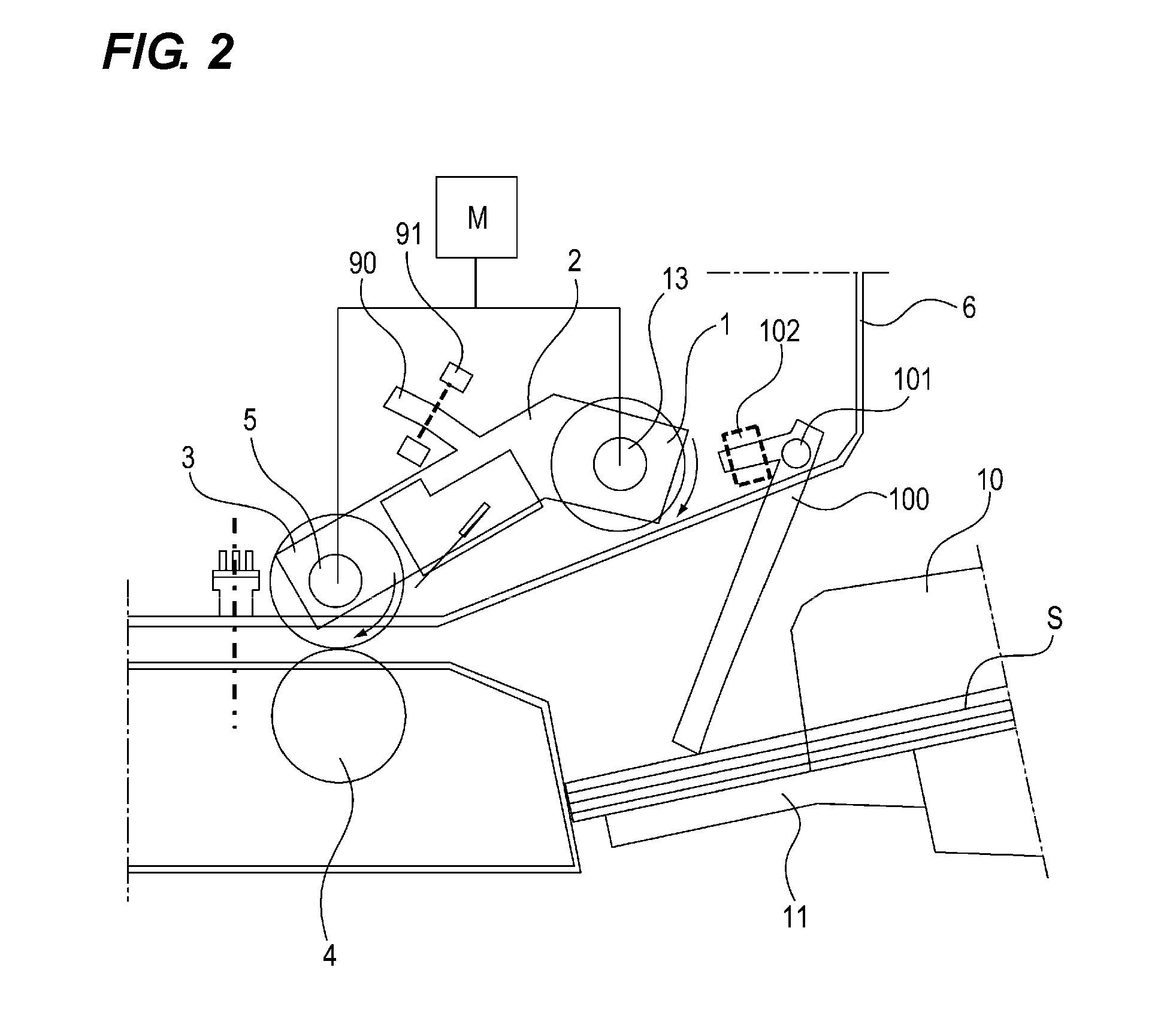
[0035] FIG. 2 schematically shows the configuration of the document tray 11 and the conveying unit. On the document tray 11, the document width regulating plate 10 for regulating the movement of the stacked document S in the width direction of the document S is provided. Further, the document tray 11 is configured to be able to be lifted up and down by a driving portion (not shown). The feeding roller 1 is rotatable around the shaft 13. Further, the roller 1 is also rotatable about the shaft 5 by the arm 2 so as to be capable of being lifted up and down with respect to the document S stacked on the document tray 11.
[0036] The opening and closing guide 6, which is an opening and closing member, is provided with the flag member 100 serving as an actuator of the document setting detection sensor 102 for detecting the presence or absence of a document on the document tray 11. The document setting detection sensor 102 uses a photo interrupter and detects that a sheet has been set on the document tray 11 when the optical axis is blocked by the flag member 100 (hereinafter referred to as sensor ON). Conversely, when the optical axis is not blocked by the flag member 100 (hereinafter referred to as sensor OFF), it is detected that a document is not set on the document tray 11.
[0037] The arm 2 is provided with the actuator 90 of the feeding position detection sensor 91 which determines a lifted position (document feeding position) of the document tray 11. The feed position detection sensor 91 uses a photo interrupter, and when the sensor is ON, the sheet feeding is possible. Conversely, when the sensor is OFF, it is necessary to lift up the document tray 11 by a driving portion (not shown).
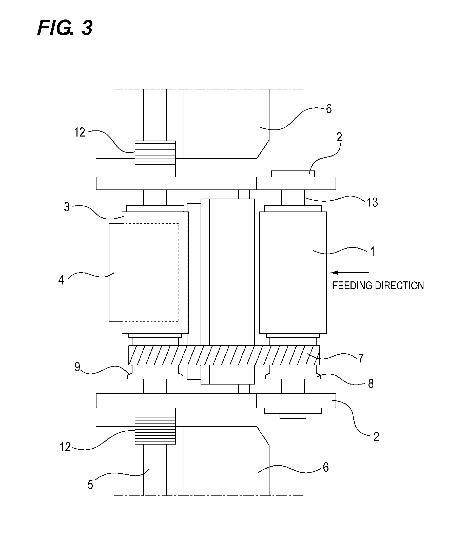
[0038] FIG. 3 is a plan view of the feeding portion and the separating portion. The pulleys 8 and 9 are provided on the feeding roller 1 and the conveying roller 3, respectively. The timing belt 7 is stretched on the pulleys 8 and 9 and transmits the driving force of the motor M (see FIG. 2) to the feeding roller 1. The arm 2 is urged by the spring clutch 12. When the motor M rotates forward, the arm 2 descends and contacts the top surface of the documents on the document tray 11. Further, when the motor M rotates forward, the feeding roller 1 and the conveying roller 3 rotate in the direction for feeding the documents and feed the documents. When the motor M rotates in the reverse direction, the spring clutch 12 is locked to lift up the arm 2.
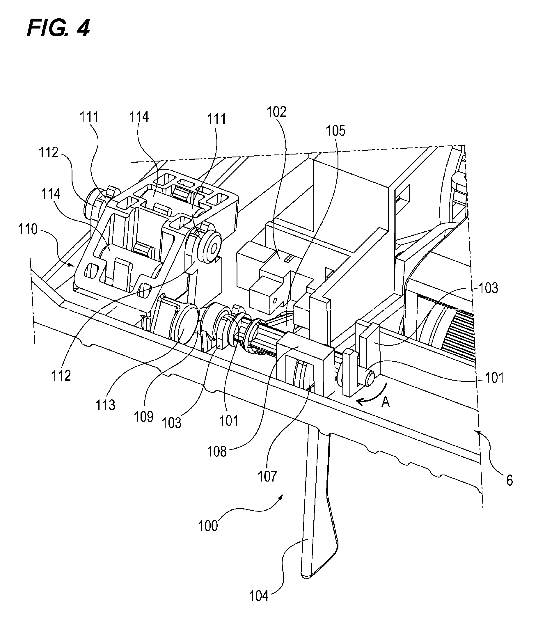
[0039] (Document Setting Detection Mechanism) Next, a document setting detection mechanism provided in the sheet conveying apparatus will be described. FIG. 4 is a perspective view of the vicinity of the document setting detection sensor.
[0040] The document setting detection sensor 102 is held by the opening and closing guide 6. The flag member 100 has two flag shaft portions 101 held by the opening and closing guide 6. The flag shaft portions 101 are held by the bearing portion 103 of the opening and closing guide 6 such that one of the flag shaft portions 101 can freely rotate and the other of the flag shaft portions 101 can freely rotate and move upward. The flag member 100 has the actuator portion 104. When the document S is set, the actuator portion 104 is pressed by the leading end of the document S so that the flag member 100 rotates about the flag shaft portions 101.
[0041] The flag member 100 has the detection portion 105 which detects that the document S has been set by the detection portion 105 blocking the light of the document set detection sensor 102 when the detection portion 105 rotates about the flag shaft portions 101. In addition, the flag member 100 has the protruding portion 107. The position of the center of gravity of the flag member 100 is determined such that a rotational moment is generated around the flag shaft portion 101 in the clockwise direction (direction of arrow A) in FIG. 4 when the opening and closing guide 6 is closed. As a result, the protruding portion 107 contacts the flag stopper portion 108 provided on the opening and closing guide 6, whereby the posture of the flag member 100 in the rotational direction is determined.
[0042] The flag member 100 has the cylindrical flag abutting portion 109. As will be described later, the flag abutting portion 109 is pressed by the assist member 110. Further, the center of gravity position of the flag member 100 is located at a position slightly away (about 0.2 mm) from the flag shaft portions 101 (the center of rotation of the flag member 100) in the horizontal direction. Therefore, the moment generated at the flag member 100 is extremely small.
[0043] The assist member 110 is rotatably attached to the opening and closing guide 6 and the assist member 110 is displaceable between a first position and a second position in accordance with opening and closing operations of the opening and closing guide 6. The assist member 110 has two assist shaft portions 111 held by the opening and closing guide 6. The assist shaft portions 111 are rotatably held by the bearing portions 112 of the opening and closing guide 6. The assist member 110 has the cylindrical assist abutting portion 113. As will be described later, the assist abutting portion 113 has a function of pressing the flag abutting portion 109 when the opening and closing guide 6 is opened.
[0044] Two weights 114 are attached to the assist member 110. The weights 114 in the present embodiment are made of SUM material having a diameter of 6 mm and a length of 12 mm. The two weights 114 are disposed on both sides of the assist shaft portions 111 such that the direction of the rotational moment of the assist member 110 by one of the weights 114 is opposite to that by the other of the weights 114.
[0045] FIG. 5 is a cross-sectional view of the assist member 110 in the vicinity of the document setting detection sensor 102. The position of the center of gravity of the assist member 110 is so determined that a moment is generated in the counterclockwise direction (direction of arrow B) with respect to the assist shaft portion 111 as shown in FIG. 5 when the open and close guide 6 is closed. The assist abutting portion 115 provided on the assist member 110 abuts against the stopper portion 116 provided on the opening and closing guide 6, whereby the posture of the assist member 110 in the rotational direction is determined. At this time, the assist member 110 is located at the first position, and the position of the center of gravity is located at a position slightly away (about 0.2 mm) from the center of rotation of the assist shaft portions 111 in the horizontal direction. As a result, the moment generated to the assist shaft portions 111 is extremely small.
[0046] FIG. 6 is a perspective view of the flag abutting portion 109 of the flag member 100 and the assist abutting portion 113 of the assist member 110 when the opening and closing guide 6 is closed.
[0047] The flag abutting portion 109 is provided at a position distant from the rotational center axis of the flag shaft portions 101. The flag abutting portion 109 has a cylindrical shape with a diameter of 3 mm, and is provided in parallel with the flag shaft portions 101. The assist abutting portion 113 is provided at a position away from the center axis of the assist shaft portions 111. The assist abutting portion 113 has a cylindrical shape with a diameter of 8 mm, and is provided in parallel with the assist shaft portions 111.
[0048] When the opening and closing guide 6 is closed, the flag abutting portion 109 and the assist abutting portion 113 are separated from each other while keeping a constant clearance without coming into contact with each other. In this state, the assist member 110 does not act on the flag member 100. As the opening and closing guide 6 is opened, the relative positional relationship between the flag shaft portions 101 and the assist shaft portions 111 is changed as described later. As a result, the flag abutting portion 109 and the assist abutting portion 113 abut against each other.
[0049] FIGS. 7A, 7B and 7C are schematic views showing movements until a document is set and fed to the document tray 11.
[0050] Before the document S is set, the flag member 100 is held with an inclination of about 83.degree. with respect to the stacking surface of the document tray 11 (FIG. 7A). When the document S is set by a user, the flag member 100 starts to rotate in the clockwise direction about the flag shaft portions 101 by the actuator portion 104 being pressed by the document S.
[0051] When the flag member 100 rotates by about 25.degree., the document S goes under the flag member 100 (FIG. 7B). At this time, the detection portion 105 blocks the light of the document setting detection sensor 102, thereby detecting that the document S has been set. By making the angle of the flag member 100 with respect to the setting direction of the document S as close to 90.degree. as possible, it is easy to detect even a document with low stiffness such as a thin paper without buckling.
[0052] When the document S is detected, the document tray 11 is lifted up by a document tray lifting motor (not shown) and is moved to a predetermined position (FIG. 7C). Thereafter, the feeding operation is performed by the feeding roller 1. After a predetermined number of sheets are fed, the document tray 11 is lifted down by the document tray lifting motor (not shown) and is moved to the initial position. The flag member 100 also returns to the initial position and the operations are completed. During this series of operations, the flag member 100 and the assist member 110 are not brought into contact with each other. The reason is that when the sheet is detected, since the flag member 100 rotates in the clockwise direction in FIG. 7, the flag abutting portion 109 rotates in a direction to retract from the assist abutting portion 113.
[0053] Further, in the present embodiment, as shown in FIG. 7, the flag shaft portions 101, which are the center of rotation of the flag member 100, are positioned at lower positions of the opening and closing guide 6 in the vertical direction in a state where the opening and closing guide 6 is located at the closed position. With this configuration, even if the angle of the flag member 100 with respect to the setting direction of the document is made as close as possible to 90.degree., it is not necessary to lengthen the flag member 100.
[0054] (Operations of Flag Member When Opening and Closing Guide is Opened) Next, the operations of the flag member 100 when the opening and closing guide 6 is opened will be described. For example, when a paper jam occurs in the reading apparatus, or when replacing parts during maintenance, the work is done with the opening and closing guide 6 being opened upward. FIG. 8 is a schematic diagram showing a state in which the opening and closing guide 6 is opened. The opening and closing guide 6 is held so as to be rotatable around the rotational shaft 117 with respect to the reading apparatus main body. When a user rotates the opening and closing guide 6 to open it, the document conveying path is exposed. At this time, the opening angle should be large enough because a certain amount of space is required from the viewpoint of workability, but if the opening angle is too large, the opening and closing guide 6 may collide with peripheral objects such as a wall surface of an installation place. Therefore, the opening angle of the opening and closing guide 6 is set to an angle at which the work is possible and the collision with surrounding objects is avoided. Then, the opening and closing guide 6 is held in a self-standing state for work to be easily done when the opening and closing guide 6 is opened.
[0055] With the opening operations of the opening and closing guide 6, the assist member 110 acts on the flag member 100. When the opening and closing guide 6 is located at the open position, the assist member 110 presses the flag member 100 so that the flag member 100 is urged toward the opening and closing guide 6. Next, the action of the assist member 110 on the flag member 100 when the opening and closing guide 6 is opened and closed will be described in detail.
[0056] FIGS. 9A and 9B are schematic views showing the positions of the flag member 100 and the assist member 110 when the opening and closing guide 6 is closed and opened. FIG. 9A shows a state in which the opening and closing guide 6 is located at a closed position, and FIG. 9B shows a state in which the opening and closing guide 6 is located at an open position.
[0057] In a state where the opening and closing guide 6 is closed, as described above, the flag member 100 and the assist member 110 are held in a state in which a slight moment is generated in the counterclockwise direction (direction of arrow C) due to their own weights without contacting each other.
[0058] As the opening and closing guide 6 is opened, the position of the assist shaft portion 111 with respect to the flag shaft portion 101 relatively moves in the counterclockwise direction, and the position of the assist shaft portion 111 in the vertical direction becomes almost the same as the position of the flag shaft portion 101. On the other hand, the flag member 100 and the assist member 110 try to maintain the posture determined by the position of the center of gravity. Therefore, the assist member rotates in the clockwise direction because of the gravity, and the assist abutting portion 113 abuts against the flag abutting portion 109 to generate a force in the direction perpendicular to each tangent (direction of arrow D). As a result, a moment is generated at the flag member 100 in the clockwise direction (the direction of the arrow E) with respect to the flag shaft portion 101 and the flag member 100 rotates against the moment in the counterclockwise direction (the direction of the arrow F) due to its own weight.
[0059] The flag member 100 continues to rotate until the assist member 110 abuts against the assist stopper portion 118 provided on the top surface of the opening and closing guide 6. At this time, the assist member 110 is located at the second position, and as shown in FIG. 9B, the flag member 100 is completely retracted inside the guide surface of the opening and closing guide 6. Even if the opening and closing guide 6 is opened further, since the rotation of the assist abutting portion 113 is restricted by the assist stopper portion 118, the flag abutting portion 109 is never pushed further. When the opening and closing guide 6 is completely opened and the opening and closing guide 6 becomes in the self-standing state, the operation of opening is completed. When closing the opening and closing guide 6, the opening and closing guide 6 returns to the initial state by the reverse procedure.
[0060] Since both the flag abutting portion 109 of the flag member 100 and the assist abutting portion 113 are formed in a circular arc configuration, the contact points are gradually moved while rotating as the opening and closing guide 6 is opened.
[0061] As described above, when the opening and closing guide 6 is opened, the flag member 100 is pressed and moved by the assist member 110 so that the flag member 100 is completely retracted inside the guide surface of the opening and closing guide 6. Therefore, it is possible to reduce the risk that the worker damages parts by contacting the flag member 100 with hands or other parts during jam recovering or maintenance operations.
[0062] As a specific example, the effect of replacing the conveying unit 121 for conveying a sheet will be described. FIG. 10 is a perspective view showing the positional relationship between the conveying unit 121 and the flag member 100 when the opening and closing guide 6 is opened.
[0063] When the opening and closing guide 6 is opened, the flag member 100 retracts inside the surface of the opening and closing guide 6 as described above. In the embodiment of FIG. 10, an accommodating portion for accommodating the flag member 100 is formed in the opening and closing guide 6 with the groove portion 119 and the protection rib 120. When the opening and closing guide 6 is opened, the flag member 100 is pressed by the assist member 110, so that the flag member 100 is retracted into the groove portion 119 provided in the opening and closing guide 6, and the flag member 100 is protected by the protection rib 120 which surrounds the flag member 100.
[0064] The conveying unit 121 has conveying members such as the feeding roller 1, the arm 2 and the conveying roller 3. The conveying unit 121 requires maintenance when it is used for a long time. Therefore, the conveying unit 121 is detachably attachable to the opening and closing guide 6. At the time of maintenance, the opening and closing guide 6 is opened, the conveying unit 121 is pulled out in the direction substantially perpendicular to the plane of the drawing in the figure, and each roller is exchanged. In pulling out the conveying unit 121, if the flag member 100 protrudes from the guide surface, the flag member 100 may collide with the conveying unit 121 so that the flag member 100 may be damaged. However, in the configuration of the above-described embodiment, since the flag member 100 is retracted inside the guide surface of the opening and closing guide 6, the risk thereof can be reduced. Therefore, in the present embodiment, the flag member 100 is disposed in the vicinity of the conveying unit 121 so as to reduce the size of the apparatus.
[0065] The flag member 100 is retracted inside the guide surface of the opening and closing guide 6 by the assist member 110, and the flag shaft portion 101, which is the center of rotation of the flag member 100, is arranged to a lower position in the vertical direction when the opening and closing guide 6 is closed, so that the length of the flag member 100 can be reduced.
[0066] In the present embodiment, the conveying unit 121 is taken as an example, but the above configuration is also effective when other replacement parts such as other conveying rollers and sensors are present in the vicinity of the flag member 100. The above configuration is also effective not only at the time of maintenance but also when there is an operation to open the opening and closing guide 6 such as jam recovering.
[0067] In this embodiment, the flag member 100 is completely retracted inside the guide surface of the opening and closing guide 6, but a certain effect can be obtained even when the flag member 100 is not completely retracted.
[0068] Further, in the present embodiment, an example in which the document tray 11 has the lift-up configuration is described, but a similar effect can be obtained with a fixed tray which does not have the lift-up configuration.
[0069] Further, in the present embodiment, the assist member 110 has the weight 114. However, a certain effect can be obtained even when the weight is not provided.
[0070] Further, in the present embodiment, the sheet conveying apparatus having the flag member 100 and the assist member 110 is used for the image reading apparatus. However, the sheet conveying apparatus can be used for an image forming apparatus having an image forming portion for forming an image on a sheet.
Second Embodiment
[0071] In the embodiment described above, when the opening and closing guide 6 is opened, the assist member 110 presses the flag member 100 while the assist member 110 and the flag member 100 are rotating in the same direction. However, the flag member 100 can be retracted while the assist member 110 and the flag member 100 are rotating in the opposite directions with each other as described next.
[0072] FIGS. 11A and 11B are schematic views showing the positions of the flag member 100 and the assist member 110 when the opening and closing guide 6 is located at the closed position and at the open position in the second embodiment. FIG. 11A shows a state in which the opening and closing guide 6 is closed, and FIG. 11B shows a state in which the opening and closing guide 6 is opened.
[0073] When the opening and closing guide 6 is closed, the flag member 100 is held by a stopper portion (not shown) in a state in which a slight moment is generated in the counterclockwise direction (direction of arrow C) by its own weight. On the other hand, the assist member 110 is held by the second stopper portion 122 in a state in which a moment is generated in the clockwise direction (direction of arrow G) by its own weight. The flag member 100 and the assist member 110 are held without contacting each other.
[0074] As the opening and closing guide 6 is opened, the relative position of the assist shaft portion 111 in the vertical direction with respect to the position of the center of gravity of the assist member 110 changes. When the opening and closing guide 6 is opened to a predetermined angle, the rotational moment due to the position of the center of gravity of the assist member 110 is switched from the clockwise direction (the direction of the arrow G) to the counterclockwise direction (the direction of the arrow H).
[0075] Therefore, the assist abutting portion 113 abuts against the flag abutting portion 109, so that a force is generated in the direction perpendicular to each tangent (direction of arrow I). As a result, a moment is generated at the flag member 100 in the clockwise direction (the direction of the arrow E) with respect to the flag shaft portion 101 so that the flag member rotates against the moment in the counterclockwise direction (the direction of the arrow F) due to its own weight. The flag member 100 rotates until the assist member 110 abuts against the assist stopper portion 118. At this time, the flag member 100 is completely retracted inside the guide surface of the opening and closing guide 6.
[0076] As described above, similarly to the first embodiment, when the opening and closing guide 6 is opened, the flag member 100 is completely retracted inside the guide surface of the opening and closing guide 6 by being pressed and moved by the assist member 110. With this configuration, it is possible to reduce the risk that the flag member 100 is damaged due to a worker contacting the flag member 100 with a hand or a part during jam recovery or maintenance operations.
Third Embodiment
[0077] In the embodiment described above, the direction of the rotational moment due to the weight of the assist member 110 is switched while the opening and closing guide 6 is moving from the closed position to the open position. However, when the opening and closing guide 6 is opened, the direction of the rotational moment due to the weight of the assist member 110 may continue to be the same.
[0078] FIGS. 12A and 12B are views for explaining the operations of the flag member 100 and the assist member 110 provided in the opening and closing guide 6 in the third embodiment. FIG. 12A shows a state in which the opening and closing guide 6 is located at a closed position, and FIG. 12B shows a state in which the opening and closing guide 6 is located at an open position.
[0079] As shown in FIGS. 12A and 12B, the flag member 100 is configured to be rotatable around the flag shaft portion 101, and the assist member 110 is configured to be rotatable around the assist shaft portion 111. When the opening and closing guide 6 is located at the closed position, the assist abutting portion 113 of the assist member 110, which is suspended by its own weight is located at a position where the assist abutting portion 113 does not act on the flag abutting portion 109 of the flag member 100.
[0080] When the opening and closing guide 6 moves from the closed position of FIG. 12A to the open position of FIG. 12B, both the assist member 110 and the flag member 100 rotate in the clockwise direction, and the assist abutting portion 113 presses the flag abutting portion 109 so that the flag member 100 is retracted inside the guide surface of the opening and closing guide 6. With this configuration, it is possible to obtain the same effect as the above-described embodiment.
[0081] While the present invention has been described with reference to exemplary embodiments, it is to be understood that the invention is not limited to the disclosed exemplary embodiments. The scope of the following claims is to be accorded the broadest interpretation so as to encompass all such modifications and equivalent structures and functions.
[0082] This application claims the benefit of Japanese Patent Application No. 2017-247537, filed Dec. 25, 2017, which is hereby incorporated by reference herein in its entirety.
* * * * *
D00000
D00001
D00002
D00003
D00004
D00005
D00006
D00007
D00008
D00009
D00010
D00011
D00012

XML
uspto.report is an independent third-party trademark research tool that is not affiliated, endorsed, or sponsored by the United States Patent and Trademark Office (USPTO) or any other governmental organization. The information provided by uspto.report is based on publicly available data at the time of writing and is intended for informational purposes only.
While we strive to provide accurate and up-to-date information, we do not guarantee the accuracy, completeness, reliability, or suitability of the information displayed on this site. The use of this site is at your own risk. Any reliance you place on such information is therefore strictly at your own risk.
All official trademark data, including owner information, should be verified by visiting the official USPTO website at www.uspto.gov. This site is not intended to replace professional legal advice and should not be used as a substitute for consulting with a legal professional who is knowledgeable about trademark law.