Cushioning Apparatus
ZHANG; Zi-Yao ; et al.
U.S. patent application number 16/226733 was filed with the patent office on 2019-06-27 for cushioning apparatus. The applicant listed for this patent is Maintek Computer (Suzhou) Co., Ltd, PEGATRON CORPORATION. Invention is credited to Hsin-Chang LU, Jian WANG, Zi-Yao ZHANG.
| Application Number | 20190193910 16/226733 |
| Document ID | / |
| Family ID | 63421976 |
| Filed Date | 2019-06-27 |


| United States Patent Application | 20190193910 |
| Kind Code | A1 |
| ZHANG; Zi-Yao ; et al. | June 27, 2019 |
CUSHIONING APPARATUS
Abstract
A cushioning apparatus includes a substrate, a first folding plate extending from the substrate, a second folding plate extending from the substrate, an annular wall, a first clamping portion, and a second clamping portion. The substrate has a first surface and a second surface opposite to each other and has an accommodation space concave towards the second surface from the first surface. The annular wall is disposed around the accommodation space. The first clamping portion is disposed on the first folding plate and is located on a same side as the second surface. The second clamping portion is disposed on the second folding plate and is located on a same side as the second surface. When the first folding plate and the second folding plate are both folded towards the second surface, the first clamping portion and the second clamping portion are clamped with each other.
| Inventors: | ZHANG; Zi-Yao; (JiangSu, CN) ; LU; Hsin-Chang; (TAIPEI CITY, TW) ; WANG; Jian; (JiangSu, CN) | ||||||||||
| Applicant: |
|
||||||||||
|---|---|---|---|---|---|---|---|---|---|---|---|
| Family ID: | 63421976 | ||||||||||
| Appl. No.: | 16/226733 | ||||||||||
| Filed: | December 20, 2018 |
| Current U.S. Class: | 1/1 |
| Current CPC Class: | B65D 81/025 20130101; B65D 5/5038 20130101; B65D 85/30 20130101; B65D 81/133 20130101 |
| International Class: | B65D 81/133 20060101 B65D081/133; B65D 5/50 20060101 B65D005/50 |
Foreign Application Data
| Date | Code | Application Number |
|---|---|---|
| Dec 22, 2017 | CN | 201721824366.6 |
Claims
1. A cushioning apparatus, comprising: a substrate having a first surface and a second surface opposite to each other and having an accommodation space concave towards the second surface from the first surface; a first folding plate extending from the substrate; a second folding plate extending from the substrate and adjacent to the first folding plate; an annular wall disposed around the accommodation space; a first clamping portion disposed on the first folding plate and located on a same side as the second surface; and a second clamping portion disposed on the second folding plate and located on a same side as the second surface, wherein when the first folding plate and the second folding plate are both folded towards the second surface of the substrate, the first clamping portion and the second clamping portion are clamped with each other.
2. The cushioning apparatus according to claim 1, wherein the substrate has a first edge and a second edge intersecting with each other, the first edge and second edge respectively extend in a first direction and a second direction, the first folding plate is disposed at the first edge, the second folding plate is disposed at the second edge, the first clamping portion comprises a first sidewall and a protruding portion, the first sidewall is connected to the first folding plate, the protruding portion protrudes from the first sidewall and protrudes towards the second edge in the first direction, the second clamping portion has a trench concave towards the second folding plate.
3. The cushioning apparatus according to claim 1, wherein when the first folding plate and the second folding plate are respectively folded towards the second surface of the substrate, a gap is formed respectively between the first clamping portion and the annular wall and between the second clamping portion and the annular wall.
4. The cushioning apparatus according to claim 1, further comprising: two pressing portions disposed on the first folding plate and the second folding plate respectively, wherein one of the two pressing portions is located on a side, far away from the second clamping portion, of the first clamping portion, the other pressing portion is located on a side, far away from the first clamping portion, of the second clamping portion, when the first folding plate and the second folding plate are folded respectively towards the second surface of the substrate, the two pressing portions press against the annular wall respectively.
5. The cushioning apparatus according to claim 4, wherein each of the two pressing portions has a top surface far away from the first folding plate and the second folding plate, the top surface of each of the pressing portion is configured to press against the annular wall, and a contour of the top surface of each of the two pressing portion is complementary to a partial outer surface of the annular wall.
6. The cushioning apparatus according to claim 4, further comprising a first supporting portion disposed on the first folding plate and located on a same side as the second surface, wherein the first supporting portion is connected with the first clamping portion and a corresponding one of the two pressing portions.
7. The cushioning apparatus according to claim 6, further comprising a second supporting portion disposed on the second folding plate and located on a same side as the second surface, wherein the second supporting portion is connected with the second clamping portion and the other one of the two pressing portions.
8. The cushioning apparatus according to claim 1, wherein the first folding plate is concave towards the second surface to form a first cushioning space, the second folding plate is concave towards the second surface to form a second cushioning space, and the first cushioning space and the first cushioning space are respectively aligned with the first clamping portion and the second clamping portion.
Description
CROSS-REFERENCE TO RELATED APPLICATIONS
[0001] This Non-provisional application claims priority under 35 U.S.C. .sctn. 119(a) on Patent Application No(s). 201721824366.6 filed in People's Republic of China on Dec. 22, 2017, the entire contents of which are hereby incorporated by reference.
BACKGROUND
Technical Field
[0002] The present disclosure relates to a cushioning apparatus, and in particular, to a cushioning apparatus having a clamping structure.
Related Art
[0003] People usually use cushioning materials in packaging boxes to protect items to prevent the items from damage due to impact or compression during shipment. To obtain a relatively strong cushioning effect, a material thickness usually needs to be increased, resulting in an increase in costs.
SUMMARY
[0004] An objective of the present disclosure is to provide a cushioning apparatus, so as to improve a cushioning effect without increasing costs.
[0005] According to an implementation of the present disclosure, a cushioning apparatus includes a substrate, a first folding plate, a second folding plate, an annular wall, a first clamping portion, and a second clamping portion. The substrate has a first surface and a second surface opposite to each other and has an accommodation space concave towards the second surface from the first surface. The first folding plate extends from the substrate. The second folding plate extends from the substrate and is adjacent to the first folding plate. The annular wall is disposed around the accommodation space. The first clamping portion is disposed on the first folding plate and is located on a same side as the second surface of the substrate. The second clamping portion is disposed on the second folding plate and is located on a same side as the second surface of the substrate. When the first folding plate and the second folding plate are both folded towards the second surface of the substrate, the first clamping portion and the second clamping portion are clamped with each other.
[0006] In one or more implementations of the present disclosure, the substrate may have a first edge and a second edge intersecting with each other. The first edge and the second edge of the substrate may respectively extend in a first direction and a second direction. The first folding plate may be disposed at the first edge of the substrate. The second folding plate may be disposed at the second edge of the substrate. The first clamping portion may include a first sidewall and a protruding portion. The first sidewall of the first clamping portion may be connected to the first folding plate. The protruding portion of the first clamping portion may protrude from the first sidewall and protrude towards the second edge of the substrate in the first direction. The second clamping portion may have a trench concave towards the second folding plate.
[0007] In one or more implementations of the present disclosure, when the first folding plate and the second folding plate are respectively folded towards the second surface of the substrate, a gap may be respectively formed between the first clamping portion and the annular wall and between the second clamping portion and the annular wall.
[0008] In one or more implementations of the present disclosure, the cushioning apparatus may further include two pressing portions. The pressing portions may be disposed on the first folding plate and the second folding plate respectively. One of the pressing portions may be located on a side, far away from the second clamping portion, of the first clamping portion. The other pressing portion may be located on a side, far away from the first clamping portion, of the second clamping portion. When the first folding plate and the second folding plate are folded respectively towards the second surface of the substrate, the pressing portions may press against the annular wall respectively.
[0009] In one or more implementations of the present disclosure, each pressing portion may have a top surface far away from the first folding plate and the second folding plate. The top surface of the pressing portion may be configured to press against the annular wall. A contour of the top surface of the pressing portion may be complementary to a partial outer surface of the annular wall.
[0010] In one or more implementations of the present disclosure, the cushioning apparatus may further include a first supporting portion. The first supporting portion may be disposed on the first folding plate and located on a same side as the second surface of the substrate. The first supporting portion may be connected with the first clamping portion and a corresponding one of the two pressing portions.
[0011] In one or more implementations of the present disclosure, the cushioning apparatus may further include a second supporting portion. The second supporting portion may be disposed on the second folding plate and located on a same side as the second surface of the substrate. The second supporting portion may be connected with the second clamping portion and the other one of the two pressing portions.
[0012] In one or more implementations of the present disclosure, the first folding plate may be concave towards the second surface to form a first cushioning space. The second folding plate may be concave towards the second surface to form a second cushioning space. The first cushioning space and the second cushioning space may be respectively aligned with the first clamping portion and the second clamping portion.
[0013] In conclusion, the first clamping portion on the first folding plate and the second clamping portion on the second folding plate of the present disclosure may be clamped with each other after the first folding plate and the second folding plate are folded, so that folded states of the first folding plate and the second folding plate can be kept and the structural stability of the cushioning apparatus can be improved. In this way, the first folding plate and the second folding plate may be perpendicular to the substrate to suffer impact in at least a first direction and/or a second direction, so as to ensure that the cushioning apparatus can achieve a cushioning effect.
BRIEF DESCRIPTION OF THE DRAWINGS
[0014] FIG. 1A and FIG. 1B are respectively a top view and a bottom view of a cushioning apparatus in a deployed state according to an implementation of the present disclosure;
[0015] FIG. 2A and FIG. 2B are respectively three-dimensional diagrams of a cushioning apparatus in a folding process according to an implementation of the present disclosure; and
[0016] FIG. 2C is a three-dimensional diagram of the structure in FIG. 2B from another angle.
DETAILED DESCRIPTION
[0017] The following descriptions provide various different implementations or embodiments to implement the subject of the present disclosure. Specific examples of elements or arrangements are discussed below to simplify the present disclosure. Certainly, the plurality of descriptions is only some examples and the present disclosure is not limited thereto. For example, a description that a first feature is formed on or above a second feature includes an implementation in which the first feature and the second feature directly contact and also includes an implementation in which another feature is formed between the first feature and the second feature and the first feature and the second feature do not directly contact in this case. In addition, numerals or texts may be repeated in different examples in the present disclosure. The objective of repetition is to simplify and clarify descriptions rather than to define a relationship between the discussed different implementations and configurations.
[0018] In addition, the terms "under", "below", "lower", "on", "above", and other similar terms representing spatial relativity are used herein to easily describe a relationship between an element or a feature and another element or feature in the drawings. The terms representing spatial relativity should cover orientations depicted in the drawings and further cover other orientations during the use or operation of an apparatus. That is, when the orientation of the apparatus is different from that in the accompanying drawings (rotation by 90 degrees or in another orientation), the terms representing spatial relativity used in this specification may also be correspondingly explained.
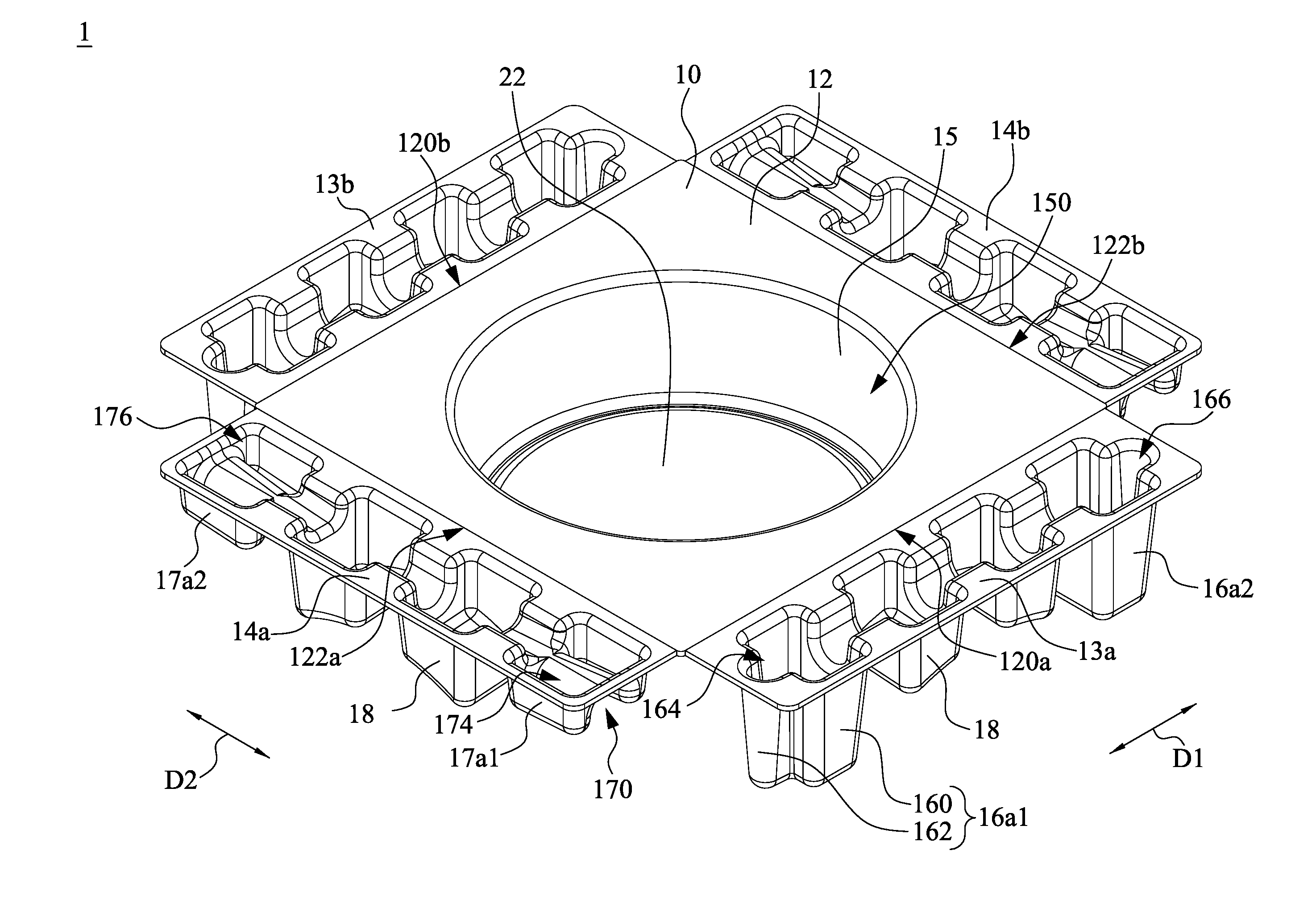
[0019] FIG. 1A and FIG. 1B are respectively a top view and a bottom view of a cushioning apparatus 1 in a deployed state according to an implementation of the present disclosure. As shown in FIG. 1A and FIG. 1B, in this implementation, the cushioning apparatus 1 includes a substrate 12, a first folding plate 13a, a second folding plate 14a, a third folding plate 13b, a fourth folding plate 14b, an annular wall 15, first clamping portions 16a1 and 16a2, second clamping portions 17a1 and 17a2, pressing portions 18, a first supporting portion 19 (see FIG. 1B), a second supporting portion 20, and a supporting bottom plate 22. In addition, in some implementations, a material of the cushioning apparatus 1 is a plastic material. In other implementations, the cushioning apparatus 1 has a paper plastic structure. The structures and functions of the elements and connection relationships between the elements are described below in detail.
[0020] In FIG. 1A and FIG. 1B, the substrate 12 has a rectangular plate body and has a first surface 10 and a second surface 11 opposite to each other. Further, the substrate 12 has a first edge 120a, a second edge 122a, a third edge 120b, and a fourth edge 122b. The first edge 120a and/or the third edge 120b of the substrate 12 intersects with the adjacent second edge 122a and fourth edge 122b and respectively extends in a first direction D1. The second edge 122a and the fourth edge 122b of the substrate 12 respectively extend in a second direction D2. In some implementations, the first direction D1 intersects with the second direction D2. In this implementation, the first direction D1 is perpendicular to the second direction D2.
[0021] In some implementations, the annular wall 15 and the supporting bottom plate 22 are formed through molding of a plastic material. In some implementations, the annular wall 15 and the supporting bottom plate 22 are formed by stamping the substrate 12. Furthermore, the annular wall 15 and the supporting bottom plate 22 are concave in the substrate 12 towards the second surface 11 from the first surface 10. In other words, the annular wall 15 protrudes from the second surface 11 from the substrate 12 (see FIG. 1B). An outer edge of the supporting bottom plate 22 contacts and is connected with an end, far away from the substrate 12, of the annular wall 15. In this implementation, the supporting bottom plate 22 has a circular plate body, but the present utility model is not limited thereto. The annular wall 15 and the supporting bottom plate 22 form an accommodation space 150 together (see FIG. 1A). In other words, the substrate 12 further has the accommodation space 150. The accommodation space 150 is concave towards the second surface 11 from the first surface 10. The annular wall 15 is disposed around the accommodation space 150. The accommodation space 150 in this implementation is used to accommodate an item (not shown) that requires shock absorption.
[0022] In FIG. 1A and FIG. 1B, the first folding plate 13a and the third folding plate 13b respectively extend in a direction away from the substrate 12 from the first edge 120a and the third edge 120b and are configured to respectively rotate with respect to the substrate 12 towards the annular wall 15 based on the first edge 120a and the third edge 120b of the substrate 12. Specifically, the first folding plate 13a and the third folding plate 13b are respectively disposed at the first edge 120a and the third edge 120b of the substrate 12. The first folding plate 13a is adjacent to and located between the second folding plate 14a and the fourth folding plate 14b. The third folding plate 13b is adjacent to and located between the second folding plate 14a and the fourth folding plate 14b. Similarly, the second folding plate 14a and the fourth folding plate 14b respectively extend in a direction away from the substrate 12 from the second edge 122a and the fourth edge 122b and are configured to respectively rotate with respect to the substrate 12 towards the annular wall 15 based on the second edge 122a and the fourth edge 122b of the substrate 12. In detail, the second folding plate 14a and the fourth folding plate 14b are respectively disposed at the second edge 122a and the fourth edge 122b of the substrate 12. The second folding plate 14a is adjacent to and located between the first folding plate 13a and the third folding plate 13b. The fourth folding plate 14b is adjacent to and located between the first folding plate 13a and the third folding plate 13b. In this implementation, folding lines are disposed at positions of the first edge 120a, the second edge 122a, the third edge 120b, and the fourth edge 122b. However, the present disclosure is not limited thereto. For example, in other implementations, all structural configurations are applicable to the present disclosure provided that the first folding plate 13a can rotate towards the annular wall 15 with respect to the substrate 12.
[0023] In FIG. 1A and FIG. 1B, the first clamping portions 16a1 and 16a2, a plurality of pressing portions 18 (where two pressing portions 18 are shown in the figures), and a plurality of first supporting portions 19 (where three first supporting portions 19 are shown in the figures) are disposed on the first folding plate 13a. The first clamping portions 16a1 and 16a2, the plurality of pressing portions 18, and the plurality of first supporting portions 19 are located on a same side of the first folding plate 13a as the second surface 11 of the substrate 12. Furthermore, the first folding plate 13a is concave towards the second surface 11 to form a first cushioning space 164 (see FIG. 1A) and a first cushioning space 166 (see FIG. 1A), and forms the first clamping portions 16a1 and 16a2. The first cushioning space 164 is aligned with the first clamping portion 16a1, and the first cushioning space 166 is aligned with the first clamping portion 16a2. In some implementations, the first clamping portions 16a1 and 16a2, the pressing portions 18, and the first supporting portions 19 are formed through molding of a plastic material. In some implementations, the first clamping portions 16a1 and 16a2, the pressing portions 18, and the first supporting portions 19 that are located on the first folding plate 13a are formed by stamping the first folding plate 13a. Similarly, the pressing portions 18 and the first supporting portions 19 are formed by concaving the first folding plate 13a.
[0024] Specifically, the first clamping portion 16a1 and the first clamping portion 16a2 are respectively located at two ends of the first folding plate 13a in the first direction D1. Furthermore, the first clamping portion 16a1 includes a first sidewall 160 and a protruding portion 162. The first sidewall 160 of the first clamping portion 16a1 is connected to and protrudes from the first folding plate 13a. The protruding portion 162 of the first clamping portion 16a1 protrudes from the first sidewall 160, and protrudes towards the second edge 122a of the substrate 12 in the first direction D1. The first clamping portion 16a2 in this implementation is substantially the same as the first clamping portion 16a1. Accordingly, the structure and function of the first clamping portion 16a2 and the connections between the first clamping portion 16a2 and other elements can be understood with regard to the related descriptions of the first clamping portion 16a1. Details are not described herein again.
[0025] In this implementation, each pressing portion 18 has a top surface 180 (see FIG. 1B) far away from the first folding plate 13a. The top surface 180 of the pressing portion 18 is configured to press against the annular wall 15. In some implementations, a contour of the top surface 180 of the pressing portion 18 is complementary to a partial outer surface of the annular wall 15. On the first folding plate 13a, the pressing portion 18 is located between the first clamping portion 16a1 and the first clamping portion 16a2. In other words, on the first folding plate 13a, one of the pressing portions 18 is located on a side, far away from the second clamping portion 17a1, of the first clamping portion 16a1. In addition, on the first folding plate 13a, one of the first supporting portions 19 is connected between the first clamping portion 16a1 and the pressing portion 18. Another one of the first supporting portions 19 is connected between the first clamping portion 16a2 and the pressing portion 18. The third one of the first supporting portions 19 is connected between two adjacent pressing portions 18. In this way, the first supporting portion 19 can improve the overall structural strength.
[0026] It should be noted that the third folding plate 13b in this implementation and the elements located on the third folding plate 13b are substantially the same as the first folding plate 13a and the first clamping portions 16a1 and 16a2, the pressing portions 18, and the first supporting portions 19 that are located on the first folding plate 13a. The structures and functions of the plurality of elements and the connections between the elements can be understood with regard to the foregoing related descriptions. Details are not described herein again.
[0027] In FIG. 1A and FIG. 1B, the second clamping portions 17a1 and 17a2, a plurality of pressing portions 18 (where two pressing portions 18 are shown in the figures), and a plurality of second supporting portions 20 (where three second supporting portions 20 are shown in the figures) are disposed on the second folding plate 14a. The second clamping portions 17a1 and 17a2, the plurality of pressing portions 18, and the plurality of second supporting portions 20 are located on a same side of the second folding plate 14a as the second surface 11 of the substrate 12. In some implementations, the second clamping portions 17a1 and 17a2, the pressing portions 18, and the second supporting portions 20 are formed through molding of a plastic material. In some implementations, the second clamping portions 17a1 and 17a2, the pressing portions 18, and the second supporting portions 20 that are located on the second folding plate 14a are formed by stamping the second folding plate 14a. Furthermore, the second folding plate 14a is concave towards the second surface 11 to form a second cushioning space 174 (see FIG. 1A) and a second cushioning space 176 (see FIG. 1A) and to form the second clamping portions 17a1 and 17a2. The second cushioning space 174 is aligned with the second clamping portion 17a1, and the second cushioning space 176 is aligned with the second clamping portion 17a2. Similarly, the pressing portions 18 and the second supporting portions 20 are formed by concaving the second folding plate 14a.
[0028] Specifically, the second clamping portion 17a1 and the second clamping portion 17a2 are respectively located at two ends of the second folding plate 14a in the second direction D2. Furthermore, the second clamping portion 17a1 has a trench 170. The trench 170 of the second clamping portion 17a1 is concave towards the second folding plate 14a. The second clamping portion 17a2 in this implementation is substantially the same as the second clamping portion 17a1. Accordingly, the structure and function of the second clamping portion 17a2 and the connections between the second clamping portion 17a2 and other components can be understood with regard to the related descriptions of the second clamping portion 17a1. Details are not described herein again.
[0029] In this implementation, the pressing portions 18 located on the second folding plate 14a is substantially the same as the pressing portions 18 located on the first folding plate 13a. Accordingly, the structure and function of the pressing portion 18 located on the second folding plate 14a and the connections between the elements can be understood with regard to the foregoing related descriptions. Details are not described herein again. It needs to be described herein that on the second folding plate 14a, the pressing portions 18 is located between the second clamping portion 17a1 and the second clamping portion 17a2. In other words, on the second folding plate 14a, one of the pressing portions 18 is located on a side, far away from the first clamping portion 16a1, of the second clamping portion 17a1. In addition, on the second folding plate 14a, one of the second supporting portions 20 is connected between the second clamping portion 17a1 and the pressing portion 18. Another one of the second supporting portions 20 is connected between the second clamping portion 17a2 and the pressing portion 18. The third one of the second supporting portions 20 is connected between two adjacent pressing portions 18. In this way, the second supporting portions 20 can improve the overall structural strength.
[0030] It should be noted that, the fourth folding plate 14b in this implementation and the elements located on the fourth folding plate 14b are substantially the same as the second folding plate 14a and the second clamping portions 17a1 and 17a2, the pressing portions 18, and the second supporting portions 20 that are located on the second folding plate 14a. The structures and functions of the plurality of elements and the connections between the elements can be understood with regard to the foregoing related descriptions. Details are not described herein again.
[0031] FIG. 2A and FIG. 2B are respectively three-dimensional diagrams of a cushioning apparatus 1 in a folding process according to an implementation of the present disclosure.
[0032] In FIG. 2A, in some implementations, when the first folding plate 13a is folded towards the second surface 11 of the substrate 12, the first clamping portion 16a1 located on the first folding plate 13a is clamped to the second clamping portion 17a1 located on the second folding plate 14a. Specifically, in this implementation, the first folding plate 13a rotating towards the annular wall 15 with respect to the substrate 12 makes the first clamping portion 16a1 located on the first folding plate 13a clamped to the second clamping portion 17a1 located on the second folding plate 14a that is already folded. In some implementations, when the first folding plate 13a is folded towards the second surface 11 of the substrate 12, the pressing portions 18 located on the first folding plate 13a respectively press against the annular wall 15, and a gap is formed between the first clamping portion 16a1 and the annular wall 15. Specifically, the first folding plate 13a rotates 12 towards the annular wall 15 with respect to the substrate until the pressing portions 18 presses against the annular wall 15. In this case, a gap is formed between the first clamping portion 16a1 and the annular wall 15.
[0033] Next, in FIG. 2B, in some implementations, when the second folding plate 14a is folded towards the second surface 11 of the substrate 12, the second clamping portion 17a1 located on the second folding plate 14a is clamped to the first clamping portion 16a1 located on the first folding plate 13a. Specifically, in this implementation, the second folding plate 14a rotating towards the annular wall 15 with respect to the substrate 12 makes the second clamping portion 17a1 located on the second folding plate 14a clamped to the first clamping portion 16a1 on the first folding plate 13a that is already folded. In some implementations, when the second folding plate 14a is folded towards the second surface 11 of the substrate 12, the pressing portions 18 located on the second folding plate 14a respectively press against the annular wall 15, and a gap is formed between the second clamping portion 17a1 and the annular wall 15. Specifically, the second folding plate 14a rotates towards the annular wall 15 with respect to the substrate 12 until the pressing portions 18 press against the annular wall 15. In this case, the trench 170 (see FIG. 2A) of the second clamping portion 17a1 is clamped to the protruding portion 162 (see FIG. 2A) of the first clamping portion 16a1 to allow the protruding portion 162 to be located in the trench 170, so that the protruding portion 162 and the trench 170 are fixed to each other. In this implementation, a gap is formed between the second clamping portion 17a1 and the annular wall 15 to form a cushioning space. In this way, when the cushioning apparatus 1 takes impact, the second clamping portion 17a1 and the first clamping portion 16a1 may maintain the clamping state, thereby improving the structural stability of the cushioning apparatus 1.
[0034] FIG. 2C is a three-dimensional diagram of the structure in FIG. 2B from another angle. In FIG. 2C, in this implementation, an accommodated item (not shown) may be disposed in the accommodation space 150 in the annular wall 15. Because a concave groove structure is provided on a lateral surface of the folded cushioning apparatus 1, cushioning distances when the accommodated item takes impact in at least the first direction D1 and/or the second direction D2 may be increased. Accordingly, the structural strength of the cushioning apparatus 1 can be improved without increasing a material thickness of the cushioning apparatus 1, so as to prevent the accommodated item from damage due to impact.
[0035] In addition, the first clamping portion 16a1 (see FIG. 2B) on the first folding plate 13a and the second clamping portion 17a1 (see FIG. 2B) on the second folding plate 14a may be clamped to each other after the first folding plate 13a and the second folding plate 14a are folded, so that the first folding plate 13a and the second folding plate 14a can maintain the folded states, and the structural stability of the cushioning apparatus 1 is improved. Accordingly, the first folding plate 13a and the second folding plate 14a may be substantially perpendicular to the substrate 12 to take impact in at least the first direction D1 and/or the second direction D2, so as to ensure that the cushioning apparatus 1 can achieve a cushioning effect.
[0036] Moreover, a force may be transferred between the first folding plate 13a and the second folding plate 14a by clamping the first clamping portion 16a1 and the second clamping portion 17a1, so as to improve a cushioning capability of the cushioning apparatus 1 under impact. For example, when an external force is applied to the first folding plate 13a, a stress from the external force may be transferred to the second folding plate 14a through the connection between the first clamping portion 16a1 (see FIG. 2B) and the second clamping portion 17a1 (see FIG. 2B). Accordingly, excessive bending of the first folding plate 13a due to the concentration of the stress on the first folding plate 13a can be prevented, so that a cushioning effect of the cushioning apparatus 1 can be improved.
[0037] In addition, because the first clamping portions 16a1 and 16a2 and the second clamping portions 17a1 and 17a2 (see FIG. 2B) respectively contain cushioning spaces 164, 166, 174, and 176, and the cushioning spaces 164, 166, 174, and 176 can improve the structural flexibility of the first clamping portions 16a1 and 16a2 and the second clamping portions 17a1 and 17a2, the first clamping portions 16a1 and 16a2 and the second clamping portions 17a1 and 17a2 can absorb a relatively large amount of impact energy under impact, so as to protect the accommodated item located in the cushioning apparatus 1.
[0038] Moreover, the pressing portions 18 (see FIG. 2B) in this implementation press against the annular wall 15 after folded. Accordingly, when the cushioning apparatus 1 is impacted, the pressing portions 18 may help to transfer a stress from the first folding plate 13a, the third folding plate 13b (see FIG. 2B), the second folding plate 14a, and/or the fourth folding plate 14b to the annular wall 15, and further to transfer the stress to the substrate 12. In addition, a contour of the pressing portions 18 is complementary to a partial outer surface of the annular wall 15 for complete contact, so that the efficiency of stress transfer can be improved, thereby further improving the cushioning effect of the cushioning apparatus 1.
[0039] The features in the foregoing implementations may enable a person of ordinary skill in the art to better understand various aspects of the present utility model. The person of ordinary skill in the art should understand that to achieve the same advantages of the implementations of the present utility model and/or the same objective, the person of ordinary skill in the art may further design or modify other processes and structures based on the present utility model. The person of ordinary skill in the art should understand that such equivalent structures do not depart from the spirit and scope of the present utility model. The person of ordinary skill in the art may make various changes, replacements and modifications herein without departing from the spirit and scope of the present utility model.
* * * * *
D00000
D00001
D00002
D00003
D00004
D00005
XML
uspto.report is an independent third-party trademark research tool that is not affiliated, endorsed, or sponsored by the United States Patent and Trademark Office (USPTO) or any other governmental organization. The information provided by uspto.report is based on publicly available data at the time of writing and is intended for informational purposes only.
While we strive to provide accurate and up-to-date information, we do not guarantee the accuracy, completeness, reliability, or suitability of the information displayed on this site. The use of this site is at your own risk. Any reliance you place on such information is therefore strictly at your own risk.
All official trademark data, including owner information, should be verified by visiting the official USPTO website at www.uspto.gov. This site is not intended to replace professional legal advice and should not be used as a substitute for consulting with a legal professional who is knowledgeable about trademark law.