Combination structure for a hose connected between an air compressor and a tire
CHOU; Wen-San
U.S. patent application number 16/221216 was filed with the patent office on 2019-06-27 for combination structure for a hose connected between an air compressor and a tire. The applicant listed for this patent is UNIK WORLD INDUSTRIAL CO., LTD.. Invention is credited to Wen-San CHOU.
| Application Number | 20190193349 16/221216 |
| Document ID | / |
| Family ID | 65235082 |
| Filed Date | 2019-06-27 |


View All Diagrams
| United States Patent Application | 20190193349 |
| Kind Code | A1 |
| CHOU; Wen-San | June 27, 2019 |
Combination structure for a hose connected between an air compressor and a tire
Abstract
A combination structure for a hose connected between a tire and an air compressor is disclosed. The air compressor includes a box in which a compressor unit and a sealant bottle are installed. The sealant bottle has an inlet and an outlet. The inlet of the sealant bottle is connected to one outlet tube of the compressor unit. The hose has a first end and a second end. The first end of the hose is adapted to be connected to the outlet tube of the sealant bottle. The second end of the hose can be connected to the combination structure, which generally includes a cap, a core element, and a plug. With the combination structure, the chemical sealant contained in the sealant bottle can be prevented from flowing out to contaminate objects due to incorrect operation or negligence.
| Inventors: | CHOU; Wen-San; (Tainan, TW) | ||||||||||
| Applicant: |
|
||||||||||
|---|---|---|---|---|---|---|---|---|---|---|---|
| Family ID: | 65235082 | ||||||||||
| Appl. No.: | 16/221216 | ||||||||||
| Filed: | December 14, 2018 |
| Current U.S. Class: | 1/1 |
| Current CPC Class: | F04B 15/00 20130101; B29L 2030/00 20130101; F04B 41/02 20130101; F04B 23/02 20130101; B60S 5/04 20130101; F04B 39/123 20130101; F04F 1/18 20130101; F04B 39/0016 20130101; B29C 73/166 20130101; B60C 29/062 20130101; F04B 39/121 20130101 |
| International Class: | B29C 73/16 20060101 B29C073/16; F04B 39/00 20060101 F04B039/00; B60S 5/04 20060101 B60S005/04; B60C 29/06 20060101 B60C029/06 |
Foreign Application Data
| Date | Code | Application Number |
|---|---|---|
| Dec 25, 2017 | TW | 106145580 |
Claims
1. A combination structure for a hose connected between an air compressor and a tire, the air compressor including a box, in which a compressor unit and a sealant bottle are installed, the compressor unit capable of being electrically started to generate compressed air; the sealant bottle contains therein a chemical sealant and has an inlet connected to an outlet tube of the compressor unit and has an outlet through which the chemical sealant is delivered; the hose has a first end adapted to be connected to the outlet of the sealant bottle, and a second end capable of being connected with the combination structure, the combination structure comprising: a cap defining an inner space which opens out at one end and defining a threaded hole which communicates with the inner space and opens out at an opposite end for threaded engagement with an air valve of the tire, wherein an inwardly extending projection is formed in the cap, between the inner space and the threaded hole, the inwardly extending projection having an annular peripheral surface defining a central opening which allows the inner space to communicate with the threaded hole; a core element fitted into the cap via an opening of the cap where the inner space opens out, the core element having a cylindrical body and a connection stem defining therein a passage and extending from the cylindrical body, beyond the opening of the cap for connection with the second end of the hose, the cylindrical body defining an inner space therein and an annular groove at its outer surface, the inner space of the cylindrical body communicating with the passage of the connection stem and having a diameter greater than the passage of the connection stem, thus forming a step therebetween; a sealing ring being fitted into the annular groove of the cylindrical body of the core element; a gasket fitted in the threaded hole against a bottom of the inwardly extending projection and defining a central opening; and a plug fitted in the cap and having a head and a column which has a diameter less than the head and extends from the head and is fitted with an sealing envelope and is inserted through the central opening of the gasket to enter the threaded hole of the cap, a spring located between the head of the plug and the step of the core element; whereby the spring normally forces the sealing envelope to seal the central opening of the inwardly extending projection of the cap, thus preventing the chemical sealant from flowing out due to incorrect operation even as the compressor unit is running.
2. The combination structure of claim 1, wherein the box is provided thereon with a rocker-type switch and a recessed connection socket, the outlet tube of the compressor unit is exposed to the recessed connection socket, and the sealant bottle is inverted to be installed on the recessed connection socket of the box such that a bottom of the sealant bottle faces up while an open end of the sealant bottle faces down.
3. The combination structure of claim 1, wherein the cap is further provided with a step above the inwardly extending projection to be in contact with a bottom of the core element where the inner space opens out; the outwardly extending projection has a conical surface at its top, between the step and the annular peripheral surface.
4. The combination structure of claim 3, wherein the connection stem of the core element is provided at its outer surface with serrated teeth to facilitate connecting with the second end of the hose.
5. The combination structure of claim 4, wherein the head of the plug is formed with an annular protrusion, which is urged against by one end of the spring; the column defines at its outer surface a plurality of parallel troughs extending along a predetermined length, thus forming a plurality of ribs between the troughs, and has a cylindrical neck portion formed between the head and a location from which the troughs extend; the sealing envelope is fitted around the cylindrical neck portion of the plug and has an outer surface being tapered off to form as a conical surface capable of being urged against an intersection of the conical surface of the cap and the annular peripheral surface of the cap.
6. The combination structure of claim 3, wherein a C-shaped ring having two opposite tongues is fitted in the cap, over the cylindrical body of the core element, around the connection stem, such that the two opposite tongues are snapped into the two through holes of the cap, so that the core element is firmly fixed to the cap.
7. The combination structure of claim 1, further comprising a fixing coil capable of fitting over the second end of the hose, so that the hose can be firmly connected with the connection stem of the core element.
8. A combination structure for a hose connected between an air compressor and a tire, the air compressor including a box, in which a compressor unit and a sealant bottle are installed, the compressor unit capable of being electrically started to generate compressed air; the sealant bottle contains therein a chemical sealant and has an inlet connected to an outlet tube of the compressor unit and has an outlet through which the chemical sealant is delivered; the hose has a first end adapted to be connected to the outlet of the sealant bottle, and a second end capable of being connected with the combination structure, the combination structure comprising: a cap defining an inner space which opens out at one end and provided with a molded-in copper nut which defines a threaded hole communicating with the inner space and opening out at an opposite end for threaded engagement with an air valve of the tire and is provided therein with a gasket defining a central opening, wherein an inwardly extending projection is formed in the cap, between the inner space and the threaded hole, the inwardly extending projection having an annular peripheral surface defining a central opening which allows the inner space to communicate with the threaded hole, the gasket being placed against a bottom of the inwardly extending projection; a core element fitted into the cap via an opening of the cap where the inner space opens out, the core element having a cylindrical body and a connection stem defining therein a passage and extending from the cylindrical body, beyond the opening of the cap for connection with the second end of the hose, the cylindrical body defining an inner space therein and an annular groove at its outer surface, the inner space of the cylindrical body communicating with the passage of the connection stem and having a diameter greater than the passage of the connection stem, thus forming a step therebetween; a sealing ring being fitted into the annular groove of the cylindrical body of the core element; and a plug fitted in the cap and having a head and a column which has a diameter less than the head and extends from the head and is fitted with an sealing envelope and is inserted through the central opening of the gasket to enter the threaded hole of the molded-in copper nut, a spring located between the head of the plug and the step of the core element; whereby the spring normally forces the sealing envelope to seal the central opening of the inwardly extending projection of the cap, thus preventing the chemical sealant from flowing out due to incorrect operation even as the compressor unit is running.
Description
(a) TECHNICAL FIELD OF THE INVENTION
[0001] The present invention relates to a combination structure for a hose connected between an air compressor and a tire, wherein the compressor includes a box in which a compressor unit and a sealant bottle having an inlet and an outlet is installed; the inlet of the sealant bottle is connected to one outlet tube of the compressor unit; the hose has a first end adapted to be connected to the outlet of the sealant bottle, and a second end connected with the combination structure which is in turn connected to an air valve of the tire; whereby the chemical sealant contained in the sealant bottle can be prevented from flowing out to contaminate the user or other objects due to incorrect operation or negligence.
(b) DESCRIPTION OF THE PRIOR ART
[0002] The inventor of the present application has dedicated a long time to development of air compressors for repairing and inflating punctured tires. For a conventional air compressor installed with a sealant bottle for repairing a tire, if a hose is not properly connected between the air compressor and the tire, when the switch of the air compressor is turned on, the chemical sealant contained in the sealant bottle may be ejected out to contaminate the user or other objects. In view of the disadvantage of conventional air compressors, the inventor of the present invention has developed an invention that can prevent the chemical sealant from flowing out due to incorrect operation or negligence. For a better performance in repairing tires, the inventor further improves the invention.
SUMMARY OF THE INVENTION
[0003] One object of the present invention is to provide a combination structure for a hose connected between a tire and an air compressor including a box in which a compressor unit and a sealant bottle are installed. The sealant bottle has an inlet and an outlet. The inlet of the sealant bottle is connected to one outlet tube of the compressor unit. The hose has a first end and a second end. The first end of the hose is adapted to be connected to the outlet of the sealant bottle. The second end of the hose can be connected to the combination structure, which generally includes a cap, a core element, and a plug. With the combination structure, the chemical sealant contained in the sealant bottle can be prevented from flowing out to contaminate objects due to incorrect operation or negligence.
[0004] Other objects, advantages, and novel features of the present invention will become more apparent from the following detailed description when taken in conjunction with the accompanying drawings.
BRIEF DESCRIPTION OF THE DRAWINGS
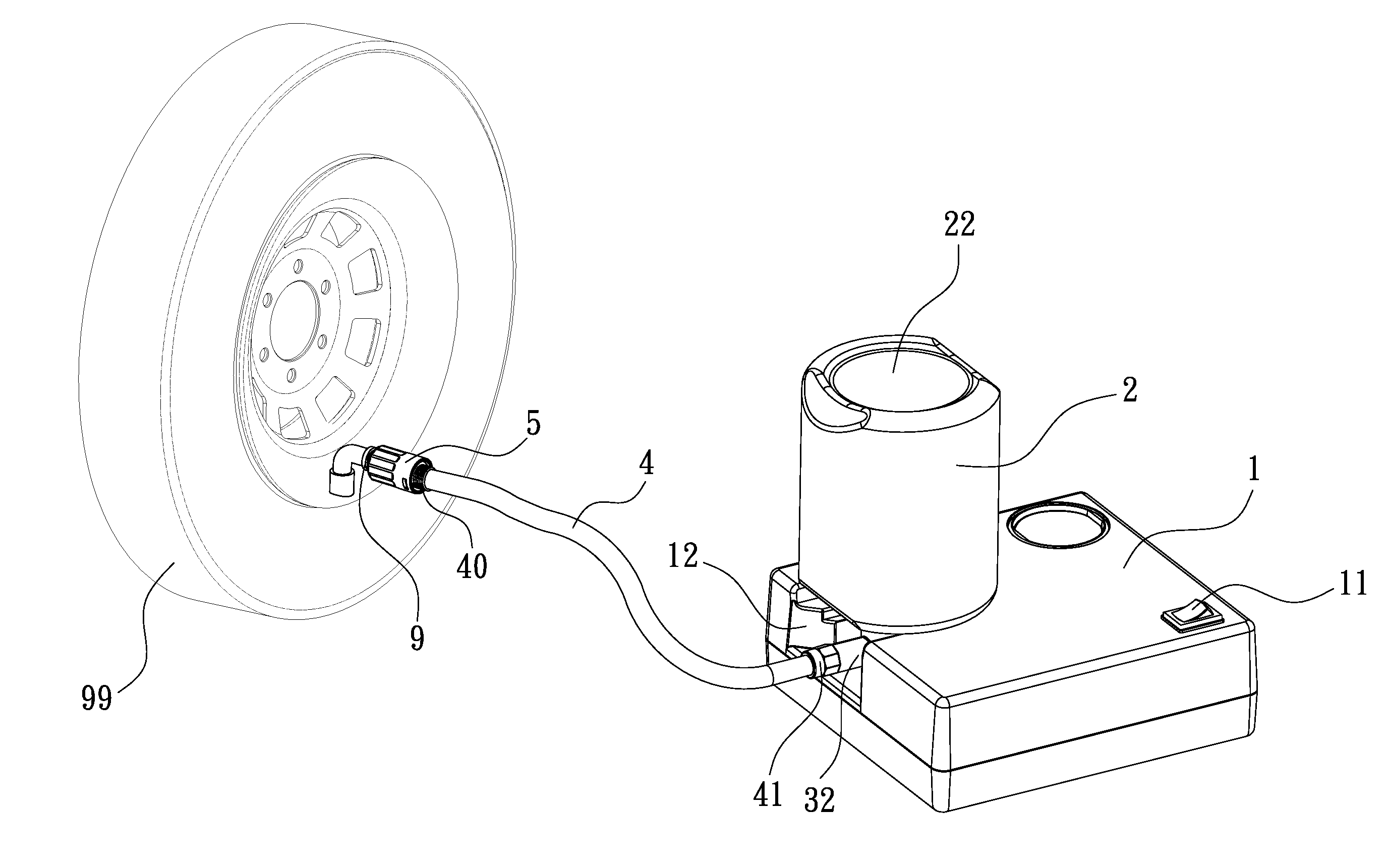
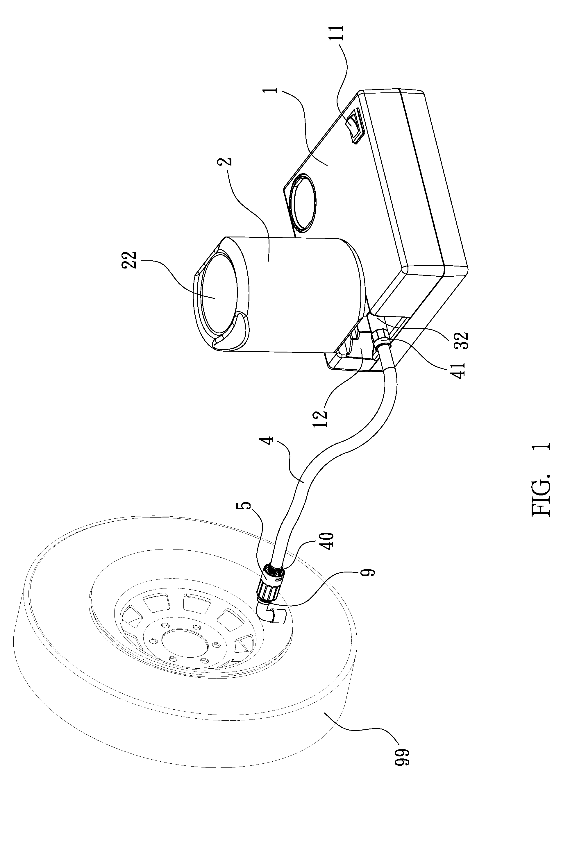
[0005] FIG. 1 shows a schematic view, wherein a box installed with a compressor unit and a sealant bottle is used to repair a tire.
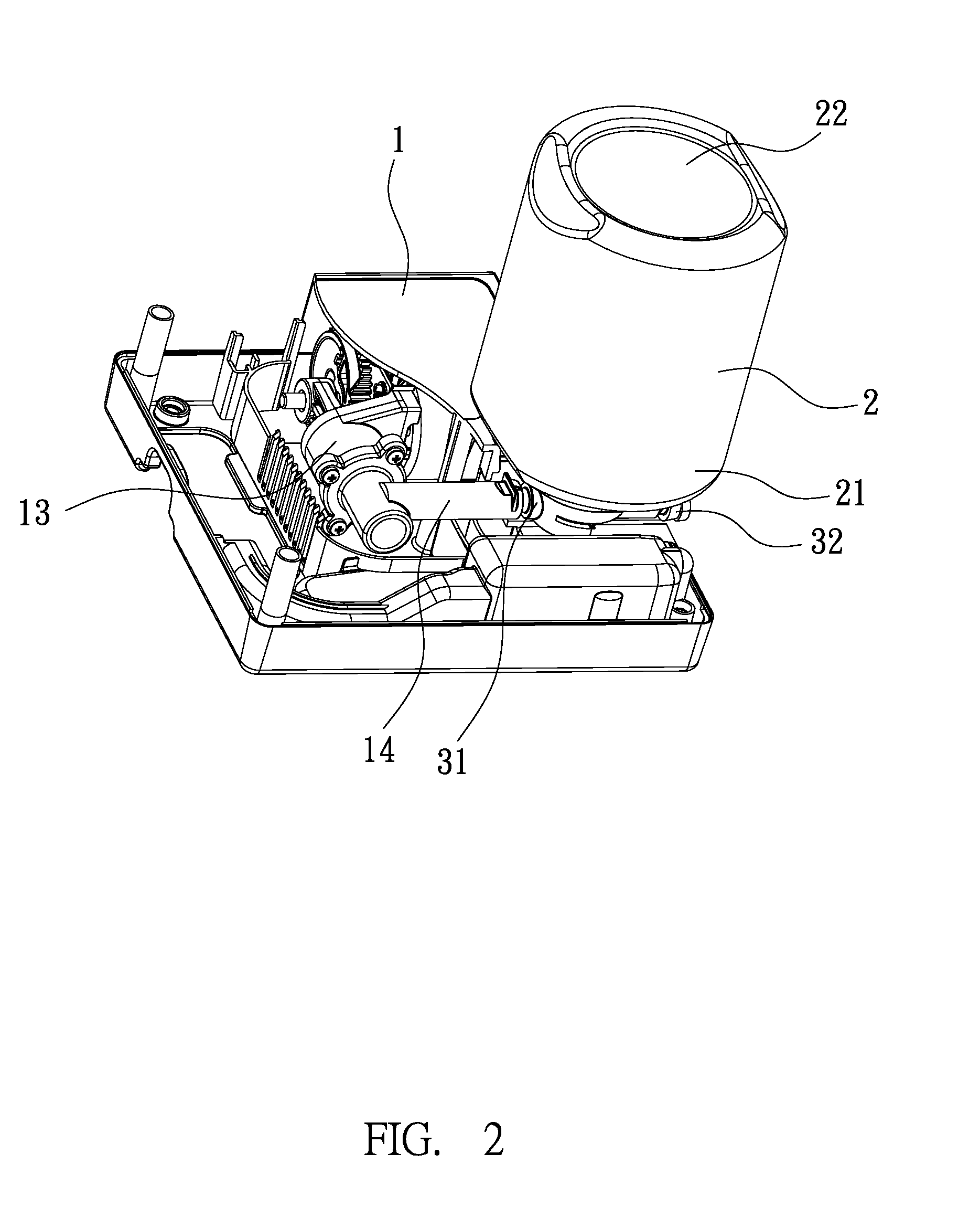
[0006] FIG. 2 shows a perspective sectional view of the box, wherein one outlet tube of the compressor unit is connected with an inlet of the sealant bottle.
[0007] FIG. 3 shows an exploded view, wherein a combination structure according to the present invention is disposed between a hose and an air valve of a tire.
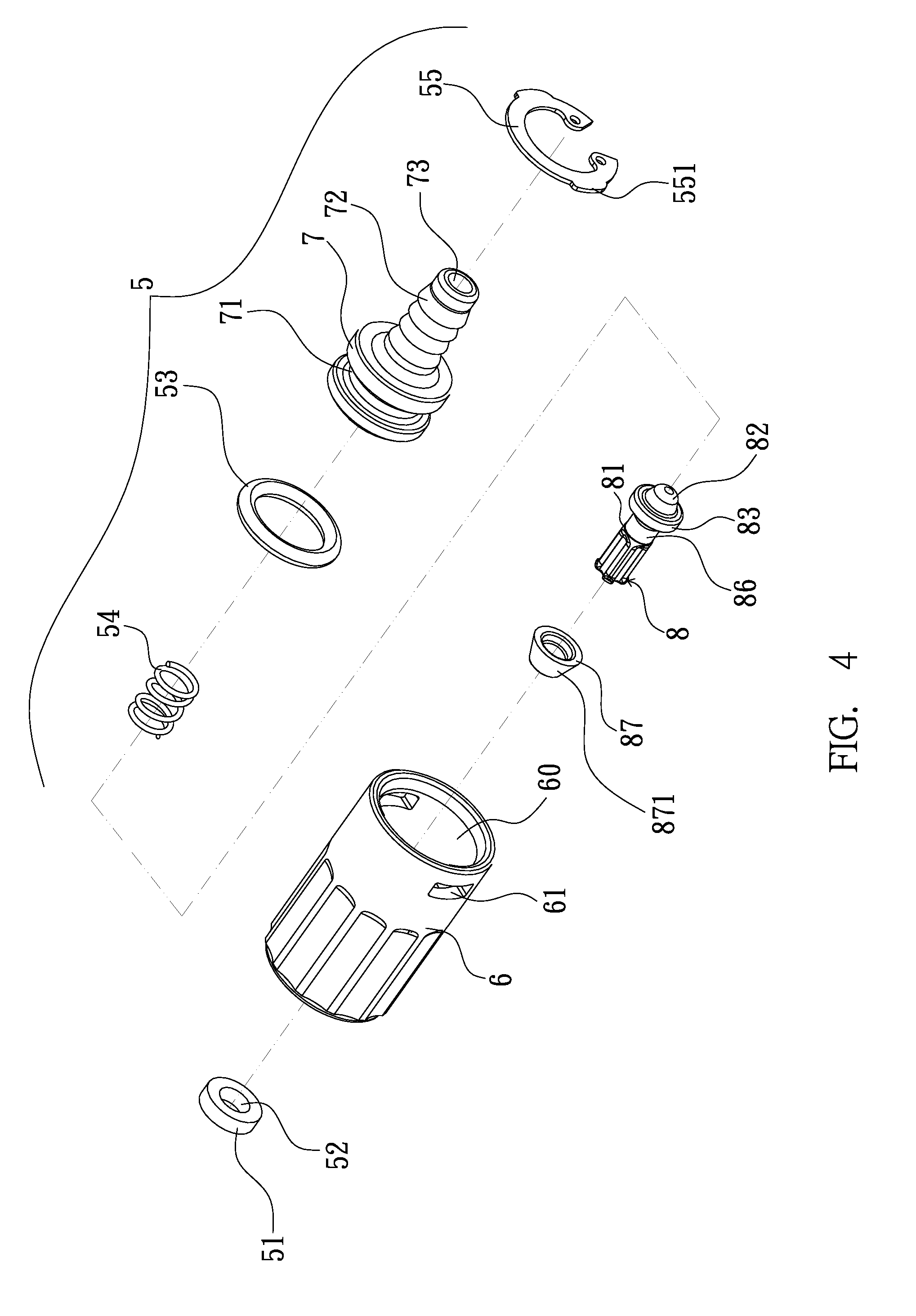
[0008] FIG. 4 shows an exploded view of one embodiment of the combination structure.
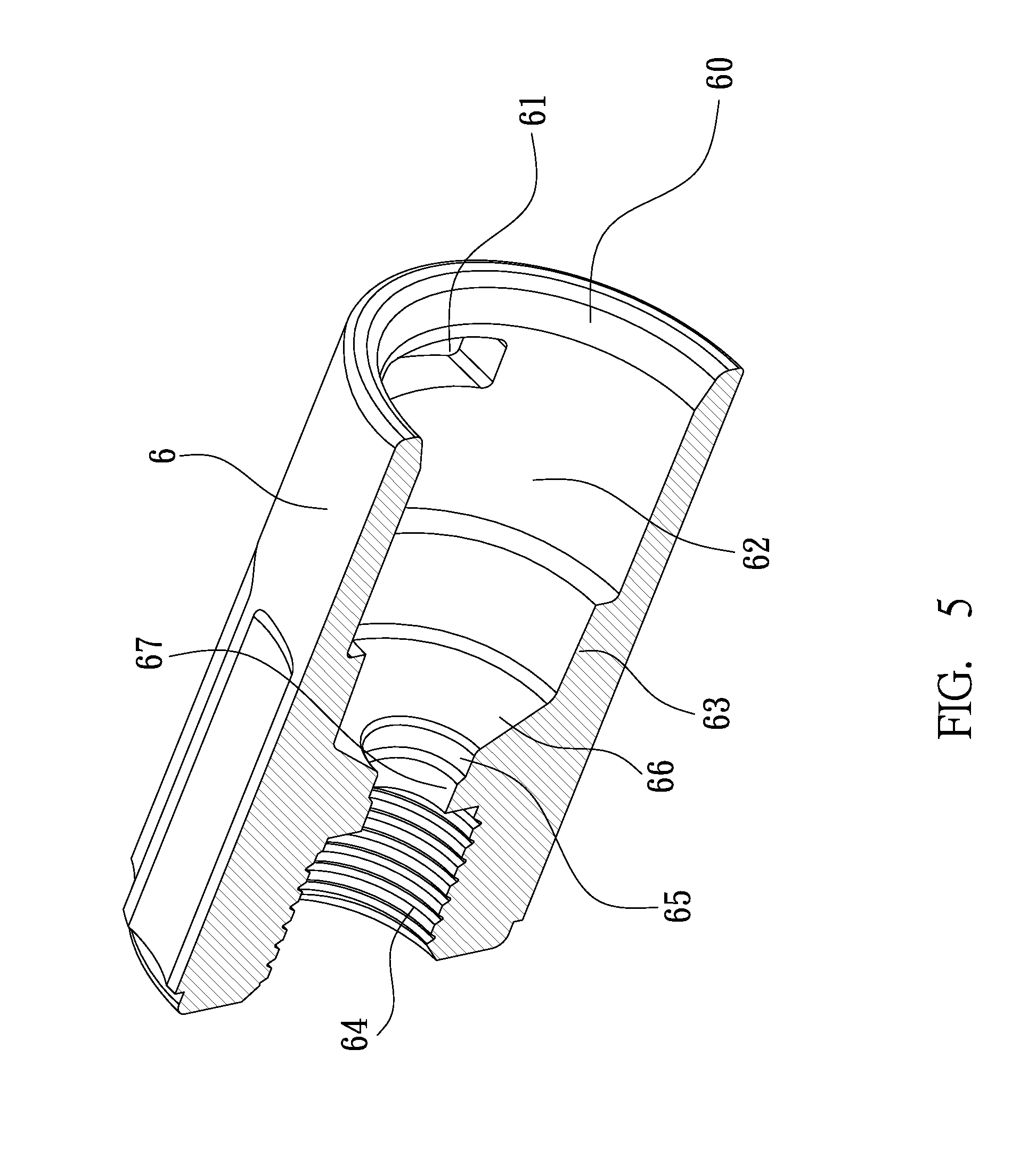
[0009] FIG. 5 shows an enlarged sectional view of a cap used in the combination structure of the embodiment.
[0010] FIG. 6 shows an enlarged sectional view of a core element used in the combination structure of the embodiment.
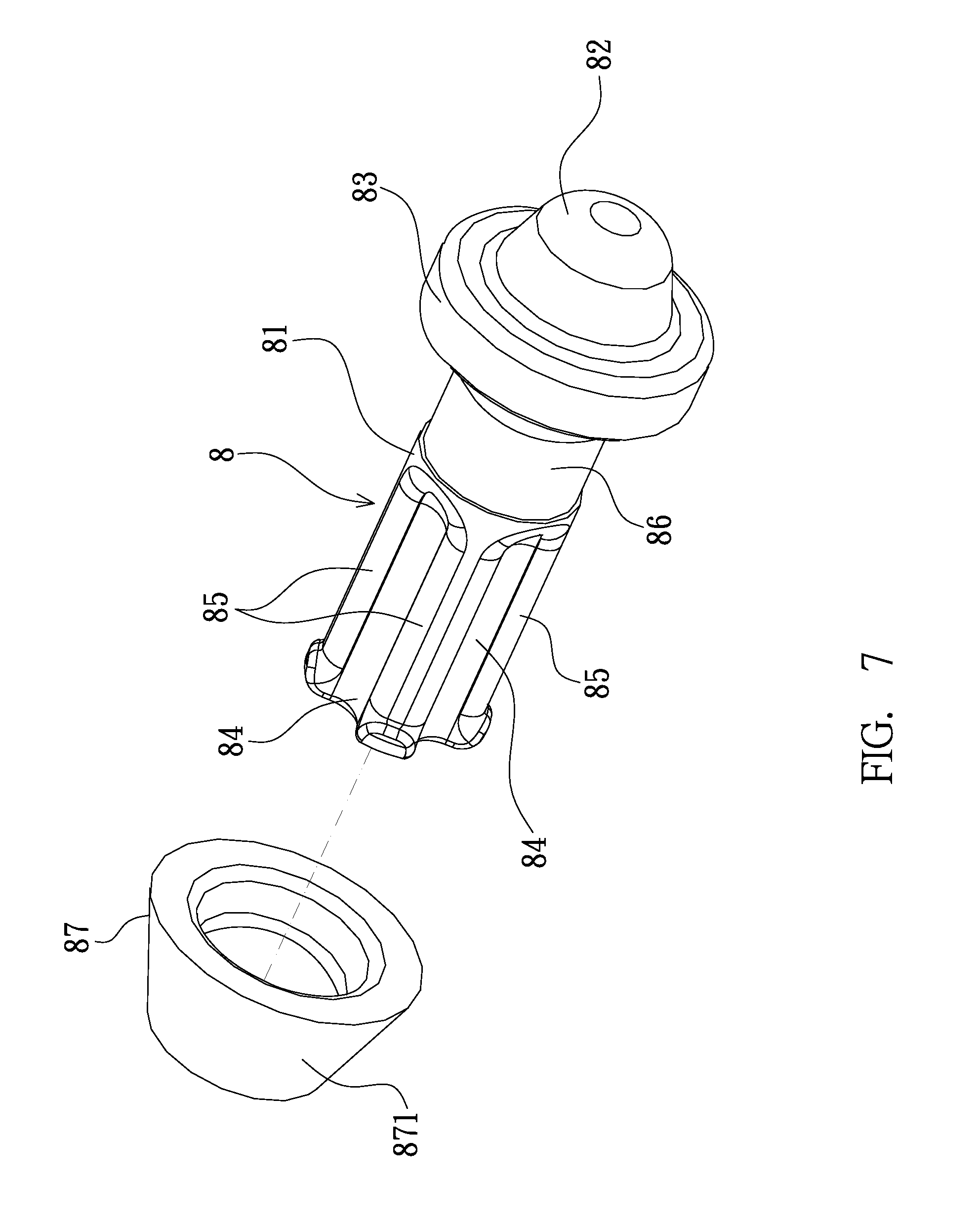
[0011] FIG. 7 shows an enlarged sectional view of a plug used in the embodiment of the combination structure.
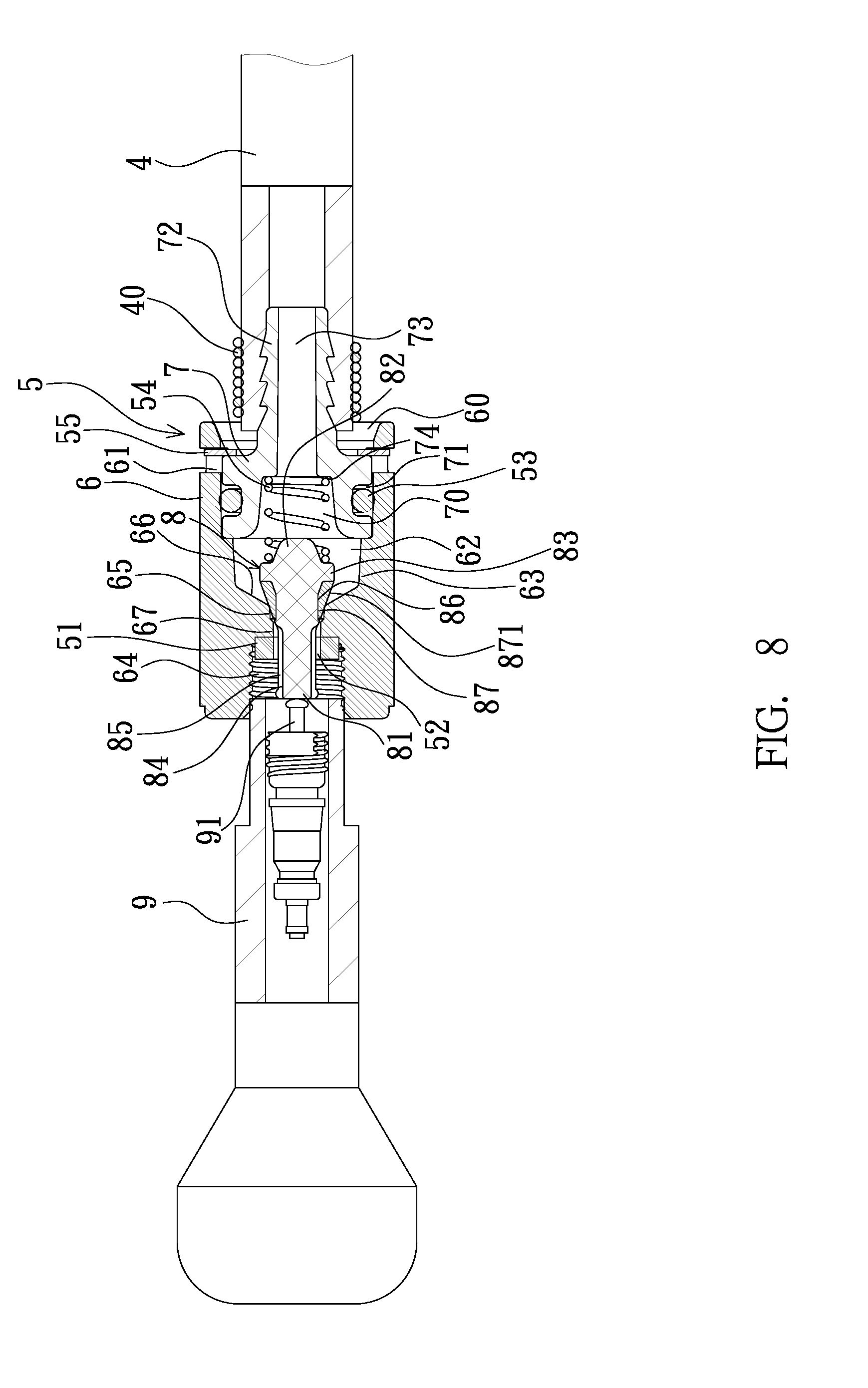
[0012] FIG. 8 shows a sectional view of the combination structure connected between a hose and an air valve of a tire, wherein the air valve is in slight threaded engagement with the combination structure.
[0013] FIG. 9 shows a sectional view of the combination structure connected between a hose and an air valve of a tire, wherein the air valve is in further threaded engagement with the combination structure, so that the air inlet of the air valve can be opened.
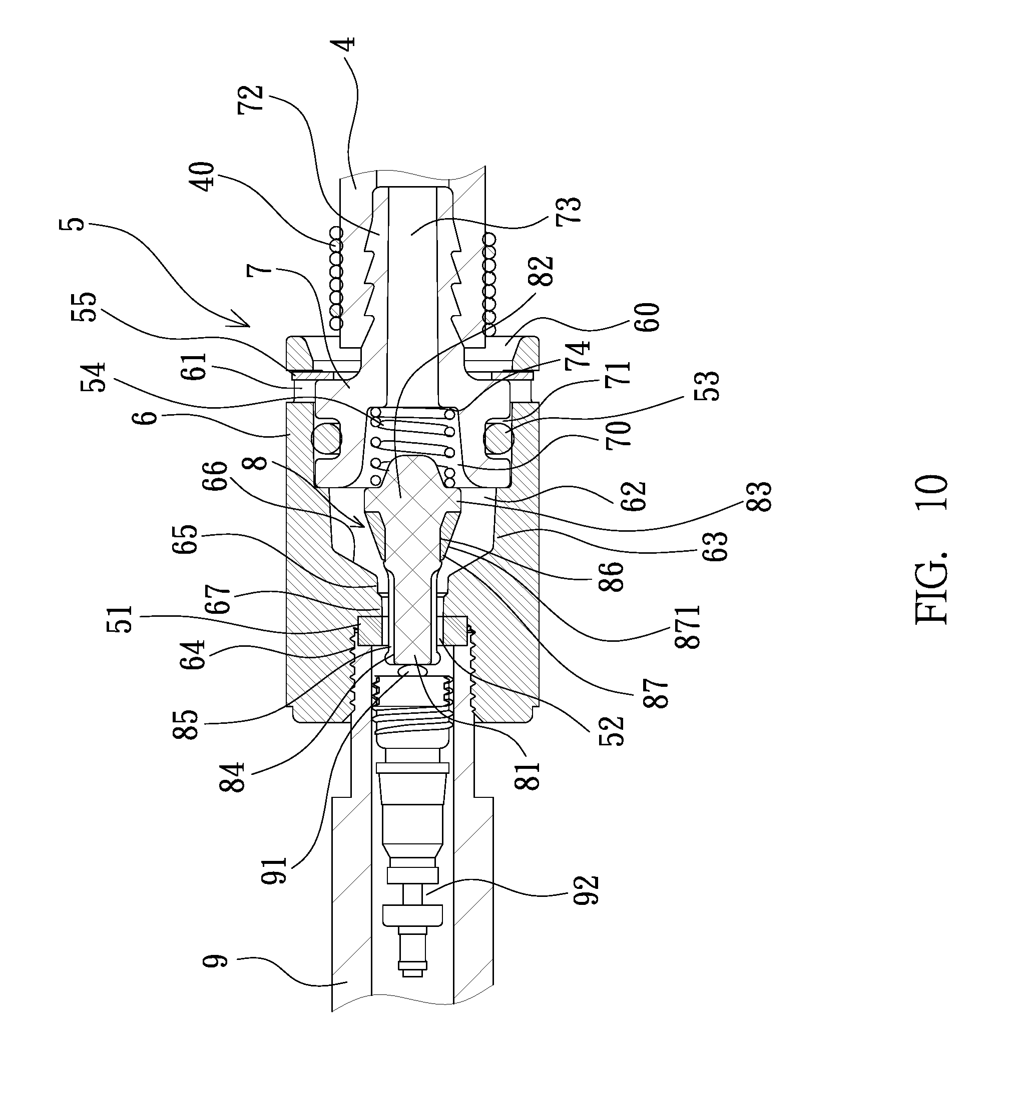
[0014] FIG. 10 shows a sectional view of the combination structure connected between a hose and an air valve of a tire, wherein the air valve is in full threaded engagement with the combination structure, so that a plug of the combination structure can be pushed to open the combination structure to allow the chemical sealant to enter the tire.
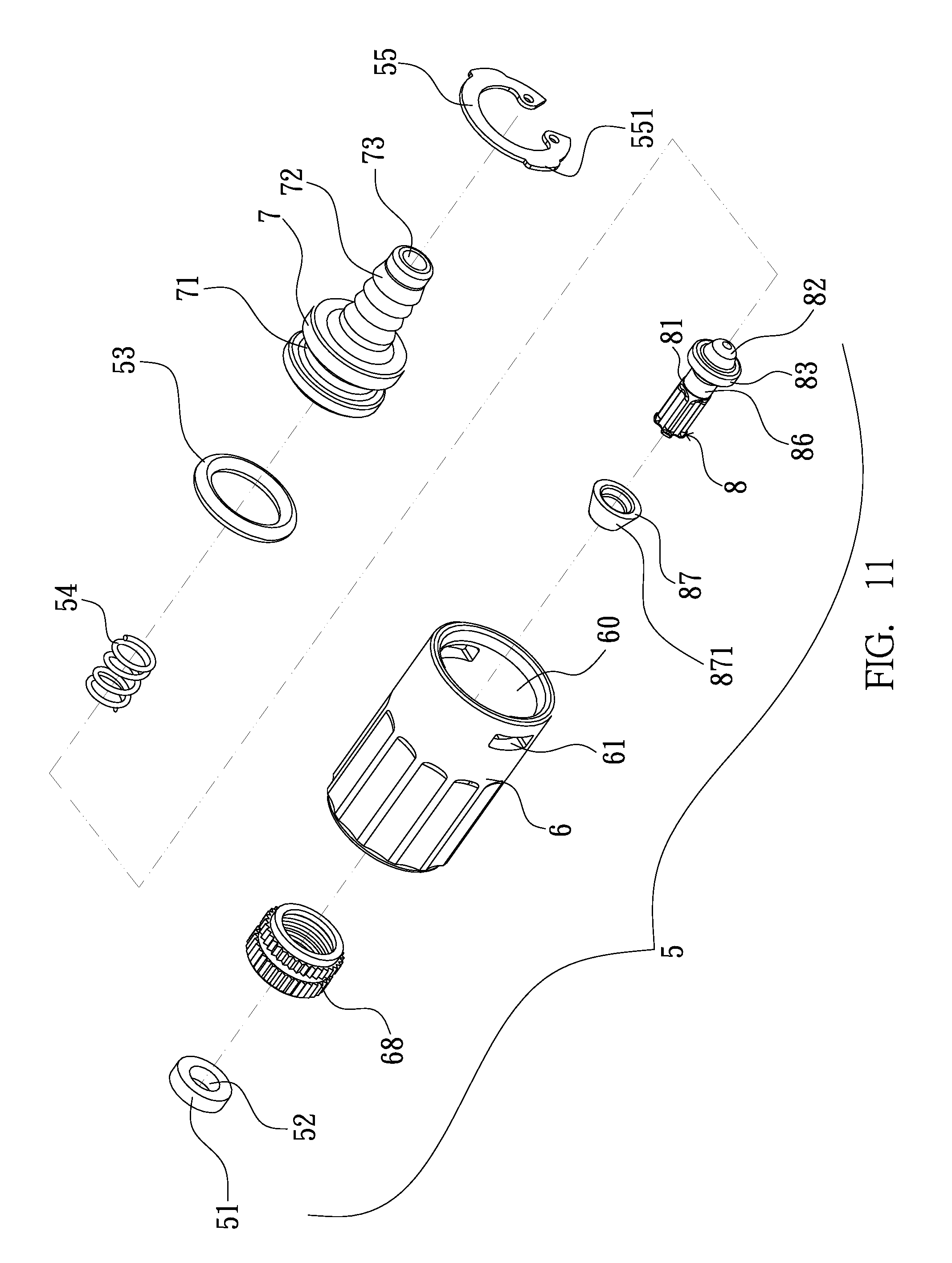
[0015] FIG. 11 shows an exploded view of a second embodiment of the combination structure.
[0016] FIG. 12 shows a sectional view of the combination structure of the second embodiment.
DETAILED DESCRIPTION OF THE PREFERRED EMBODIMENTS
[0017] Referring to FIGS. 1 through 3, an air compressor for vehicles generally includes a box 1, in which a compressor unit 13 and a sealant bottle 2 are installed, wherein the box 1 is provided thereon with a rocker-type switch 11 and a recessed connection socket 12. The compressor unit 13 can be started by turning on the switch 11. An outlet tube 14 of the compressor unit 13 can be exposed to the recessed connection socket 12. The sealant bottle 2 contains therein a chemical sealant and has an inlet 31 and an outlet 32 at its open end 21. The inlet 31 of the sealant bottle 2 can be connected to the outlet tube 14 of the compressor unit 13. The outlet 32 of the sealant bottle 2 allows the chemical sealant to be delivered from the bottle. The sealant bottle 2 is inverted to be installed on the recessed connection socket 12 of the box 1 such that the bottom of the sealant bottle 2 faces up while the open end 21 of the sealant bottle 2 faces down. A hose 4 can be connected between the compressor unit 13 and a tire 99. The hose 4 has a first end 41 adapted to be connected to the outlet 32 of the sealant bottle 2, and a second end connected with a combination structure 5, which is in turn connected with an air valve 9 of the tire. Using electrical power from a vehicle or other DC power supplies, the compressor unit 13 can be started to generate compressed air, which can force the chemical sealant to pass through the hose 4 and the air valve 9 to enter the tire 99 to achieve the purpose of repairing and inflating the tire.
[0018] FIGS. 4 through 10 show one embodiment of the combination structure 5 of the present invention, which generally includes a cylindrical cap 6, a core element 7, and a plug 8. The cylindrical cap 6 defines an inner space 62 which opens out at one end to form an opening 60 and defines a threaded hole 64 which communicates with the inner space 62 and opens out at an opposite end (see FIG. 5). Furthermore, the cap 6 defines two opposite through holes 61 at a location close to the opening 60. An inwardly extending projection 67 is formed in the cap 6 between the inner space 62 and the threaded hole 64. The inwardly extending projection 67 has an annular peripheral surface 65 defining a central opening which allows the inner space 62 to communicate with the threaded hole 64. A step 63 is formed at a surface of the inner space 62, above the inwardly extending projection 67. The inwardly extending projection 67 has a conical surface 66 at its top, between the step 63 and the annular peripheral surface 65. The core element 7, which are roughly cylindrical in shape (see FIG. 6), has a cylindrical body (not labeled) and a connection stem 72. The cylindrical body of the core element 7 defines an inner space 70 therein and an annular groove 71 at its outer surface. The connection stem 72 extends from the cylindrical body and defines therein a passage 73 communicating with the inner space 70 and is provided with serrated teeth (not labeled) at its outer surface to facilitate connecting with the second end of the hose 4. The inner space 70 has a diameter greater than the passage 73, thus forming a step 74 therebetween. The core element 7 can be fitted into the cap 6 via the opening 60 to be in contact with the step 63. A sealing ring 53 can be fitted into the annular groove 71 of the cylindrical body of the core element 7 to keep airtight. A gasket 51 is fitted in the threaded hole 64 against a bottom of the inwardly extending projection 67 and defines a central opening 52 (see FIGS. 4 and 8). The plug 8 can be fitted in the cap 6 via the opening 60 for normally closing a flow path which is partly formed by the inner space 62 and the threaded hole 64. The plug 8 has a head 82 and a column 81 extending from the head 82 (see FIG. 7). The head 82 is formed with an annular protrusion 83, so that the head 82 has a diameter greater than the column 81. The column 81 is fitted with an sealing envelope 87 and inserted through the central opening 52 of the gasket 51 to enter the threaded hole 64 of the cap 6. More specifically, the column 81 defines a plurality of parallel troughs 84 at its outer surface, along a predetermined length of the column, thus forming a plurality of ribs 85 between the troughs 84. Also, the column 81 has a cylindrical neck portion 86 formed between the head 82 and a location from which the troughs 84 extend. As the column 81 is inserted into the threaded hole 64 of the cap 6, the troughs 84 along with the column 81 extends through the central opening 52 of the gasket 51 located in the threaded hole 64 of the cap 6. The sealing envelope 87 can be fitted around the cylindrical neck portion 86 of the plug 8. The sealing envelope 87 has an outer surface 871 being tapered off in the direction of the column's end to form as a conical surface which can be urged against the intersection of the conical surface 66 of the cap 6 and the annular peripheral surface 65 of the cap 6 (see FIG. 8). A compression spring 54 is located between the head 82 of the plug 8 and the step 74 of the core element 70.
[0019] More specifically, one end of the spring 54 is urged against the annular protrusion 83 of the head 82, while an opposite end of the spring 54 is urged against the step 74. A C-shaped ring 55 having two opposite tongues 551 is fitted in the cap 6, over the cylindrical body of the core element 7, around the connection stem 72, such that the two opposite tongues 551 are snapped into the two through holes 61 of the cap 6, so that the core element 7 can be firmly fixed to the cap 6. The second end of the hose 4 can be fitted over the connection stem 72 of the core element 7 of the combination structure 5. A fixing coil 40 can be fitted over the second end of the hose 4 to have the hose 4 firmly connected with the connection stem 72 of the combination structure 5.
[0020] FIG. 8 shows a state of the combination structure 5, wherein the threaded hole 64 of the combination structure 5 is in slight threaded engagement with the air valve 9 of the tire 99. Under this circumstance, the sealing envelope 87 is urged by the spring 54 to have its conical surface 871 against the intersection of the conical surface 66 and the annular peripheral surface 65, thus sealing the central opening of the inwardly extending projection 67, so that the chemical sealant cannot flow through the central opening 52 of the gasket 51 located in the threaded hole 64 and thus can prevent the chemical sealant from passing through the combination structure 5 even as the switch 11 of the compressor unit 13 is turned on.
[0021] When the threaded hole 64 of the combination structure 5 is in further threaded engagement with the air valve 9 of the tire 99, the plug 8 can push a central pin 91 of the air valve 9 to open an air inlet 92 of the valve (see FIG. 9). As the threaded hole 64 is in full thread engagement with the air valve 9, as shown in FIG. 10, the plug 8 can be pushed by the central pin 91 of the air valve 9 to move towards the core element 7, so that the conical surface 871 can be clear of the intersection of the conical surface 66 and the annular peripheral surface 65 of the cap 6, and thus a flow path for the chemical sealant can be formed. Specifically, the chemical sealant being forced by the compressed air can pass through the passage 73, the inner space 70, the central opening 52 of the gasket 51 (with the assistance of the troughs 84 of the plug 8), the threaded hole 64, and the air inlet 92 of the valve 9 to enter the tire 99 to repair and inflate the tire until a normal pressure within the tire is reached.
[0022] FIGS. 11 and 12 show a second embodiment of the combination structure, wherein the cap 6 is provided with a molded-in copper nut 68 at one end opposite to the opening 60. The copper nut 68 defines a threaded hole communicating with the inner space 62 and opening out at the end opposite to the opening 60. The gasket 51, which defines a central opening 52 coaxial with the threaded hole of the copper nut 68, is provided in molded-in copper nut 68, in contact with a bottom of the inwardly extending projection 67.
[0023] As a summary, the present invention provides a combination structure for a hose connected between an air compressor and a tire for repairing and inflating the tire. With the combination structure, the problem of chemical sealant flowing out due to incorrect operation of an air compressor or negligence can be prevented.
* * * * *
D00000
D00001
D00002
D00003
D00004
D00005
D00006
D00007
D00008
D00009
D00010
D00011
D00012

XML
uspto.report is an independent third-party trademark research tool that is not affiliated, endorsed, or sponsored by the United States Patent and Trademark Office (USPTO) or any other governmental organization. The information provided by uspto.report is based on publicly available data at the time of writing and is intended for informational purposes only.
While we strive to provide accurate and up-to-date information, we do not guarantee the accuracy, completeness, reliability, or suitability of the information displayed on this site. The use of this site is at your own risk. Any reliance you place on such information is therefore strictly at your own risk.
All official trademark data, including owner information, should be verified by visiting the official USPTO website at www.uspto.gov. This site is not intended to replace professional legal advice and should not be used as a substitute for consulting with a legal professional who is knowledgeable about trademark law.