Multifunctional Wheel Burr Removing Device
XUE; Bowen ; et al.
U.S. patent application number 15/938641 was filed with the patent office on 2019-06-27 for multifunctional wheel burr removing device. This patent application is currently assigned to CITIC Dicastal CO.,LTD. The applicant listed for this patent is CITIC Dicastal CO.,LTD. Invention is credited to Jiandong Guo, Xuesong Wang, Bowen XUE.
| Application Number | 20190193231 15/938641 |
| Document ID | / |
| Family ID | 62210676 |
| Filed Date | 2019-06-27 |


| United States Patent Application | 20190193231 |
| Kind Code | A1 |
| XUE; Bowen ; et al. | June 27, 2019 |
MULTIFUNCTIONAL WHEEL BURR REMOVING DEVICE
Abstract
Disclosed in the application are a multifunctional wheel burr removing device, which includes a lower brush system, a turnover system, a synchronous clamping and rotating system, an upper brush system and the like. The multifunctional wheel burr removing device may be used for removing burrs from a riser, a cap seam allowance, a valve hole, bolt holes and bolt counter bores of a wheel, and has the characteristics of high automation degree, high removal efficiency, advanced process, strong universality, and safe and stable performance at the same time.
| Inventors: | XUE; Bowen; (Qinhuangdao, CN) ; Wang; Xuesong; (Qinhuangdao, CN) ; Guo; Jiandong; (Qinhuangdao, CN) | ||||||||||
| Applicant: |
|
||||||||||
|---|---|---|---|---|---|---|---|---|---|---|---|
| Assignee: | CITIC Dicastal CO.,LTD Qinhuangdao CN |
||||||||||
| Family ID: | 62210676 | ||||||||||
| Appl. No.: | 15/938641 | ||||||||||
| Filed: | March 28, 2018 |
| Current U.S. Class: | 1/1 |
| Current CPC Class: | B24B 27/0076 20130101; B24B 9/00 20130101; B24B 41/005 20130101; B24B 41/02 20130101; B24B 41/06 20130101; B24B 41/067 20130101; B24B 27/0069 20130101; B24B 29/005 20130101; B24B 47/12 20130101; B24B 9/04 20130101 |
| International Class: | B24B 9/00 20060101 B24B009/00; B24B 41/00 20060101 B24B041/00; B24B 41/02 20060101 B24B041/02; B24B 41/06 20060101 B24B041/06; B24B 47/12 20060101 B24B047/12 |
Foreign Application Data
| Date | Code | Application Number |
|---|---|---|
| Dec 21, 2017 | CN | 2017113943483 |
Claims
1. A multifunctional wheel burr removing device, comprising a frame, cylinders I, a lower fixed plate, belt pulleys I, shafts I, bearing seats I, a synchronous belt I, a lower lifting plate, gears I, racks I, guide rails I, sliding supports, servo motors I, shafts II, bearing seats II, springs, shafts III, brush heads, a servo motor II, a turnover support I, a belt pulley II, a cylinder II, a synchronous belt II, a left bearing seat I, a belt pulley III, a shaft IV, guide rails II, a left sliding plate, racks II, left shafts, left bearing seats II, V-shaped rollers, a gear II, a brush disc, a belt pulley IV, a shaft V, a synchronous belt III, a rotating support, a belt pulley V, a servo motor III, a shaft VI, a bearing seat III, a servo motor IV, a turnover support II, a servo motor V, a servo electric cylinder, an upper sliding plate, an upper lifting plate, a guide rail III, upper guide posts, upper guide sleeves, cylinders III, a brush shaft, right shafts, right bearing seats I, a right sliding plate, a servo motor VII, a right bearing seat II, a shaft VII, a servo motor VII, lower guide posts and lower guide sleeves, a lower lifting system comprises: the two cylinders I and the four lower guide sleeves are all fixed on the lower fixed plate, and the four lower guide posts matched with the lower guide sleeves are fixed below the lower lifting plate; and the output ends of the cylinders I are articulated with the lower part of the lower lifting plate; a burr brushing unit comprises: the bearing seat I is fixed below the lower lifting plate, and the shaft I is mounted inside the bearing seat I via bearings; the gear I is fixed at the upper end of the shaft I, and the belt pulley I is fixed at the lower end of the shaft I; the bottom of the sliding support is mounted above the lower lifting plate via the guide rail I; the rack I is fixed below the sliding support, and engaged with the gear I; the bearing seat II is fixed above a top plate of the sliding support; the shaft II is mounted inside the bearing seat II via bearings; the shaft III is in sliding fit with the upper end of the shaft II; the spring is mounted inside the shaft II, and arranged below the shaft III; the brush head is fixed at the top of the shaft III; the servo motor I is fixed below the top of the sliding support, and the output end of the servo motor I is connected with the lower part of the shaft II; a lower brush system comprises five burr brushing units, which are uniformly distributed in the circumferential direction; the synchronous belt I is connected with the belt pulleys I in the five burr brushing units; the servo motor VII is fixed below the lower lifting plate, and the output end of the servo motor VII is connected with the lower part of the shaft I in one burr brushing unit; a turnover system comprises: the servo motor II is fixed at the lower part of the left side of the frame, and the belt pulley II is fixed at the output end of the servo motor II; the left bearing seat I is fixed on the left side of the frame, and arranged above the servo motor II; the shaft IV is mounted inside the left bearing seat I via bearings; the belt pulley III is fixed on the right side of the shaft IV; the right end of the shaft IV is fixed at the left end of the turnover support I; the belt pulley II is connected with the belt pulley III via the synchronous belt II; the right bearing seat II is fixed on the right side of the frame; the shaft VII is mounted inside the right bearing seat II via bearings, and the left end of the shaft VII is fixed at the right end of the turnover support I; a synchronous clamping and rotating system comprises: the gear II is fixed above a bottom plate of the turnover support I; the left sliding plate is mounted above the bottom plate of the turnover support I via a guide rail II; the cylinder II is also fixed above the bottom plate of the turnover support I, and the output end of the cylinder II is connected with the lower part of the left sliding plate; a rack II is fixed below the left sliding plate, and the two left bearing seats II are fixed above the left sliding plate; the two left shafts are mounted inside the left bearing seats II via bearings; two V-shaped rollers are respectively mounted above the two left shafts; the right sliding plate is mounted above the bottom plate of the turnover support I via a guide rail II; a rack II is fixed below the right sliding plate, and the two right bearing seats I are fixed above the right sliding plate; the rack II below the left sliding plate and the rack II below the right sliding plate are simultaneously engaged with the gear II; the two right shafts are mounted inside the right bearing seats I via bearings; two V-shaped rollers are respectively mounted above the two right shafts; the servo motor VII is fixed below the right sliding plate, and the output end of the servo motor VII is connected with the lower end of one right shaft; an upper brush system comprises: the shaft V is mounted below the rotating support via bearings; the brush disc is fixed at the leftmost end of the shaft V; the belt pulley IV is fixed at the left end of the shaft V, and arranged between the brush disc and the rotating support; the brush shaft is mounted at the right end of the shaft V; the servo motor III is fixed on the left side of the rotating support, and the belt pulley V is fixed at the output end of the servo motor III; the belt pulley IV is connected with the belt pulley V via the synchronous belt III; the bearing seat III is fixed below a bottom plate of the turnover support II; the shaft VI is mounted inside the bearing seat III via bearings; the servo motor IV is fixed above the bottom plate of the turnover support II, and the output end of the servo motor IV is connected with the top of the shaft VI; the top of the rotating support is fixed below the shaft VI; the turnover support II is mounted below the upper sliding plate via a pin roll; the servo motor V is fixed on a side plate below the upper sliding plate, and the output end of the servo motor V is connected with the pin roll for connecting the turnover support II; the upper sliding plate is mounted below the upper lifting plate via the guide rail III; the servo electric cylinder is fixed below the upper lifting plate, and the output end of the servo electric cylinder is connected with the upper sliding plate; an upper lifting system comprises: the two cylinders III and the four upper guide sleeves are fixed at the top of the frame; the four upper guide posts matched with the four upper guide sleeves are fixed at the top of the upper lifting plate; and the output ends of the two cylinders III are articulated with the upper part of the upper lifting plate.
Description
CROSS-REFERENCE TO RELATED APPLICATIONS
[0001] This application claims priority to Chinese Patent Application No. 201711394348.3 filed on Dec. 21, 2017, which is hereby incorporated by reference in its entirety.
TECHNICAL FIELD
[0002] The present application relates to burr removing device, and specifically, to multifunctional wheel burr removing device.
BACKGROUND ART
[0003] In the machining process of an aluminum alloy wheel, burrs will definitely be produced at the machined positions of a riser, a cap seam allowance, a valve hole, bolt holes, bolt hole counter bores and the like. If the produced burrs are not removed in time, the subsequent coating effect will be seriously affected, and even the wheel is corroded in advance during use.
SUMMARY OF THE INVENTION
[0004] The aim of the present application is to provide multifunctional wheel burr removing device, which may be used for removing burrs from a riser, a cap seam allowance, a valve hole, bolt holes and bolt counter bores of a wheel.
[0005] In order to fulfill the above aim, the technical solution of the present application is: multifunctional wheel burr removing device, includes a frame, cylinders I, a lower fixed plate, belt pulleys I, shafts I, bearing seats I, a synchronous belt I, a lower lifting plate, gears I, racks I, guide rails I, sliding supports, servo motors I, shafts II, bearing seats II, springs, shafts III, brush heads, a servo motor II, a turnover support I, a belt pulley II, a cylinder II, a synchronous belt II, a left bearing seat I, a belt pulley III, a shaft IV, guide rails II, a left sliding plate, racks II, left shafts, left bearing seats II, V-shaped rollers, a gear II, a brush disc, a belt pulley IV, a shaft V, a synchronous belt III, a rotating support, a belt pulley V, a servo motor III, a shaft VI, a bearing seat III, a servo motor IV, a turnover support II, a servo motor V, a servo electric cylinder, an upper sliding plate, an upper lifting plate, a guide rail III, upper guide posts, upper guide sleeves, cylinders III, a brush shaft, right shafts, right bearing seats I, a right sliding plate, a servo motor VII, a right bearing seat II, a shaft VII, a servo motor VII, lower guide posts, lower guide sleeves and the like.
[0006] A lower lifting system includes: the two cylinders I and the four lower guide sleeves are all fixed on the lower fixed plate, and the four lower guide posts matched with the lower guide sleeves are fixed below the lower lifting plate; and the output ends of the cylinders I are articulated with the lower part of the lower lifting plate.
[0007] A burr brushing unit includes: the bearing seat I is fixed below the lower lifting plate, and the shaft I is mounted inside the bearing seat I via bearings; the gear I is fixed at the upper end of the shaft I, and the belt pulley I is fixed at the lower end of the shaft I; the bottom of the sliding support is mounted above the lower lifting plate via the guide rail I; the rack I is fixed below the sliding support, and engaged with the gear I; the bearing seat II is fixed above a top plate of the sliding support; the shaft II is mounted inside the bearing seat II via bearings; the shaft III is in sliding fit with the upper end of the shaft II; the spring is mounted inside the shaft II, and arranged below the shaft III; the brush head is fixed at the top of the shaft III; the servo motor I is fixed below the top of the sliding support, and the output end of the servo motor I is connected with the lower part of the shaft II.
[0008] A lower brush system includes five burr brushing units, which are uniformly distributed in the circumferential direction; the synchronous belt I is connected with the belt pulleys I in the five burr brushing units; the servo motor VII is fixed below the lower lifting plate, and the output end of the servo motor VII is connected with the lower part of the shaft I in one burr brushing unit.
[0009] A turnover system includes: the servo motor II is fixed at the lower part of the left side of the frame, and the belt pulley II is fixed at the output end of the servo motor II; the left bearing seat I is fixed on the left side of the frame, and arranged above the servo motor II; the shaft IV is mounted inside the left bearing seat I via bearings; the belt pulley III is fixed on the right side of the shaft IV; the right end of the shaft IV is fixed at the left end of the turnover support I; the belt pulley II is connected with the belt pulley III via the synchronous belt II; the right bearing seat II is fixed on the right side of the frame; the shaft VII is mounted inside the right bearing seat II via bearings, and the left end of the servo motor VII is fixed at the right end of the turnover support I.
[0010] A synchronous clamping and rotating system includes: the gear II is fixed above a bottom plate of the turnover support I; the left sliding plate is mounted above the bottom plate of the turnover support I via a guide rail II; the cylinder II is also fixed above the bottom plate of the turnover support I, and the output end of the cylinder II is connected with the lower part of the left sliding plate; a rack II is fixed below the left sliding plate, and the two left bearing seats II are fixed above the left sliding plate; the two left shafts are mounted inside the left bearing seats II via bearings; two V-shaped rollers are respectively mounted above the two left shafts; the right sliding plate is mounted above the bottom plate of the turnover support I via a guide rail II; a rack II is fixed below the right sliding plate, and the two right bearing seats I are fixed above the right sliding plate; the rack II below the left sliding plate and the rack II below the right sliding plate are simultaneously engaged with the gear II; the two right shafts are mounted inside the right bearing seats I via bearings; two V-shaped rollers are respectively mounted above the two right shafts; the servo motor VII is fixed below the right sliding plate, and the output end of the servo motor VII is connected with the lower end of one right shaft.
[0011] An upper brush system includes: the shaft V is mounted below the rotating support via bearings; the brush disc is fixed at the leftmost end of the shaft V; the belt pulley IV is fixed at the left end of the shaft V, and arranged between the brush disc and the rotating support; the brush shaft is mounted at the right end of the shaft V; the servo motor III is fixed on the left side of the rotating support, and the belt pulley V is fixed at the output end of the servo motor III; the belt pulley IV is connected with the belt pulley V via the synchronous belt III; the bearing seat III is fixed below a bottom plate of the turnover support II; the shaft VI is mounted inside the bearing seat III via bearings; the servo motor IV is fixed above the bottom plate of the turnover support II, and the output end of the servo motor IV is connected with the top of the shaft VI; the top of the rotating support is fixed below the shaft VI; the turnover support II is mounted below the upper sliding plate via a pin roll; the servo motor V is fixed on a side plate below the upper sliding plate, and the output end of the servo motor V is connected with the pin roll for connecting the turnover support II; the upper sliding plate is mounted below the upper lifting plate via the guide rail III; the servo electric cylinder is fixed below the upper lifting plate, and the output end of the servo electric cylinder is connected with the upper sliding plate.
[0012] An upper lifting system includes: the two cylinders III and the four upper guide sleeves are fixed at the top of the frame; the four upper guide posts matched with the four upper guide sleeves are fixed at the top of the upper lifting plate; and the output ends of the two cylinders III are articulated with the upper part of the upper lifting plate.
[0013] In the working process, the cylinder II drives the four V-shaped rollers via the gear II and the racks II to synchronously clamp a wheel, and the servo motor VII drives the clamped wheel to rotate; the servo motor III drives the brush disc via the synchronous belt III to rotate; the cylinders III drive the brush disc via the upper guide posts to descend, and when the brush disc contacts a riser of the wheel, burrs thereon may be removed; the angle of the brush shaft in the horizontal direction may be adjusted under the drive of the servo motor IV via the shaft VI, the included angle between the brush shaft and the vertical direction may be adjusted under the drive of the servo motor V via the turnover support II, and the position of the brush shaft in the horizontal direction may be adjusted under the drive of the servo electric cylinder via the guide rail III; after the angle and position of the brush shaft are adjusted to be proper, burrs may be removed from a cap seam allowance and a valve hole of the wheel with the use of the brush shaft; the five brush heads are adjusted to pitch circles of bolt holes of the wheel under the drive of the servo motor VII via the synchronous belt I, the gears I, the racks I and the like; the servo motor VII drives the wheel to rotate till the center of each bolt hole is just concentric with the axis of each brush head; the cylinders I drive the brush heads via the lower guide posts to ascend, and when the brush heads contact the bolt holes of the wheel, burrs may be simultaneously removed from the bolt holes; the servo motor II drives the turnover support I and the wheel via the synchronous belt II to turn over 180 degrees, and burrs may also be removed from bolt hole counter bores by the same method.
[0014] The present application may be used for removing burrs from a riser, a cap seam allowance, a valve hole, bolt holes and bolt counter bores of a wheel, and has the characteristics of high automation degree, high removal efficiency, advanced process, strong universality, and safe and stable performance at the same time.
BRIEF DESCRIPTION OF DRAWINGS
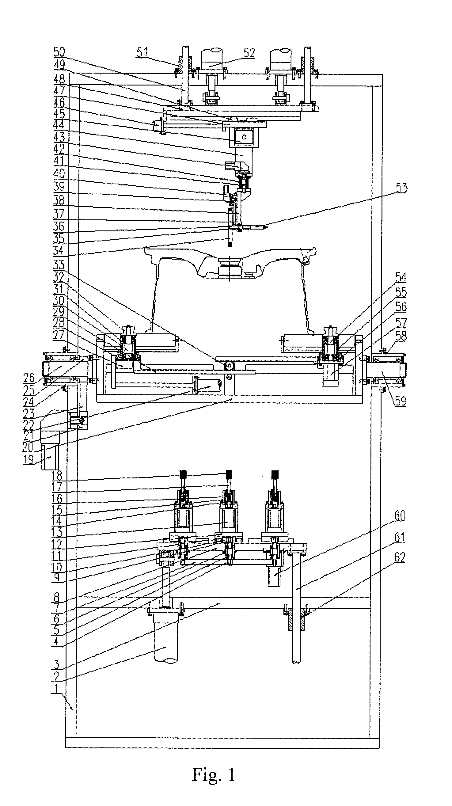
[0015] FIG. 1 is a front view of multifunctional wheel burr removing device of the present application.
[0016] FIG. 2 is a left view of the multifunctional wheel burr removing device of the present application.
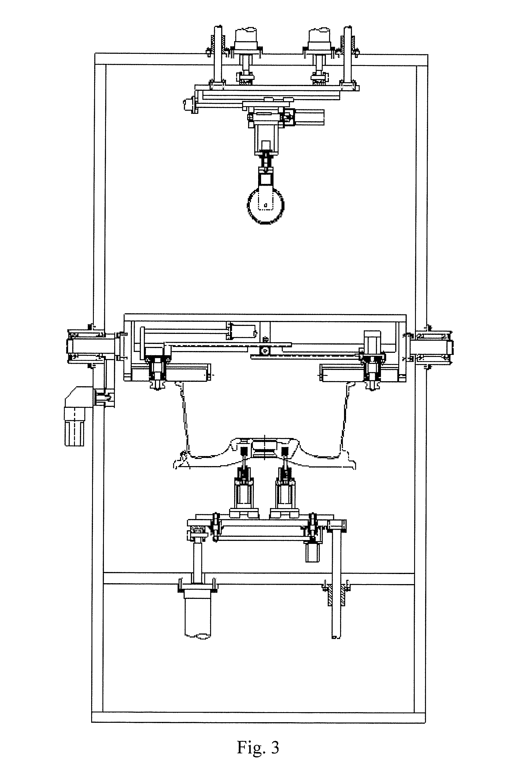
[0017] FIG. 3 is a front view of the multifunctional wheel burr removing device of the present application after a wheel is turned over.
[0018] FIG. 4 is a partial top view of the multifunctional wheel burr removing device of the present application.
[0019] In which, 1-frame, 2-cylinder I, 3-lower fixed plate, 4-belt pulley I, 5-shaft I, 6-bearing seat I, 7-synchronous belt I, 8-lower lifting plate, 9-gear I, 10-rack I, 11-guide rail I, 12-sliding support, 13-servo motor I, 14-shaft II, 15-bearing seat II, 16-spring, 17-shaft III, 18-brush head, 19-servo motor II, 20-turnover support I, 21-belt pulley II, 22-cylinder II, 23-synchronous belt II, 24-left bearing seat I, 25-belt pulley III, 26-shaft IV, 27-guide rail II, 28-left sliding plate, 29-rack II, 30-left shaft, 31-left bearing seat II, 32-V-shaped roller, 33-gear II, 34-brush disc, 35-belt pulley IV, 36-shaft V, 37-synchronous belt III, 38-rotating support, 39-belt pulley V, 40-servo motor III, 41-shaft VI, 42-bearing seat III, 43-servo motor IV, 44-turnover support II, 45-servo motor V, 46-servo electric cylinder, 47-upper sliding plate, 48-upper lifting plate, 49-guide rail III, 50-upper guide post, 51-upper guide sleeve, 52-cylinder III, 53-brush shaft, 54-right shaft, 55-right bearing seat I, 56-right sliding plate, 57-servo motor VII, 58-right bearing seat II, 59-shaft VII, 60-servo motor VII, 61-lower guide post, 62-lower guide sleeve.
DETAILED DESCRIPTION OF THE INVENTION
[0020] Specific details and working conditions of equipment provided by the present application will be described below in combination with the accompanying drawings.
[0021] The device includes a frame 1, cylinders I 2, a lower fixed plate 3, belt pulleys I 4, shafts I 5, bearing seats I 6, a synchronous belt I 7, a lower lifting plate 8, gears I 9, racks I 10, guide rails I 11, sliding supports 12, servo motors I 13, shafts II 14, bearing seats II 15, springs 16, shafts III 17, brush heads 18, a servo motor II 19, a turnover support I 20, a belt pulley II 21, a cylinder II 22, a synchronous belt II 23, a left bearing seat I 24, a belt pulley III 25, a shaft IV 26, guide rails II 27, a left sliding plate 28, racks II 29, left shafts 30, left bearing seats II 31, V-shaped rollers 32, a gear II 33, a brush disc 34, a belt pulley IV 35, a shaft V 36, a synchronous belt III 37, a rotating support 38, a belt pulley V 39, a servo motor III 40, a shaft VI 41, a bearing seat III 42, a servo motor IV 43, a turnover support II 44, a servo motor V 45, a servo electric cylinder 46, an upper sliding plate 47, an upper lifting plate 48, a guide rail III 49, upper guide posts 50, upper guide sleeves 51, cylinders III 52, a brush shaft 53, right shafts 54, right bearing seats I 55, a right sliding plate 56, a servo motor VII 57, a right bearing seat II 58, a shaft VII 59, a servo motor VII 60, lower guide posts 61, lower guide sleeves 62 and the like.
[0022] A lower lifting system includes: the two cylinders I 2 and the four lower guide sleeves 62 are all fixed on the lower fixed plate 3, and the four lower guide posts 61 matched with the lower guide sleeves 62 are fixed below the lower lifting plate 8; and the output ends of the cylinders I 2 are articulated with the lower part of the lower lifting plate 8.
[0023] A burr brushing unit includes: the bearing seat I 6 is fixed below the lower lifting plate 8, and the shaft I 5 is mounted inside the bearing seat I 6 via bearings; the gear I 9 is fixed at the upper end of the shaft I 5, and the belt pulley I 4 is fixed at the lower end of the shaft I 5; the bottom of the sliding support 12 is mounted above the lower lifting plate 8 via the guide rail I 11; the rack I 10 is fixed below the sliding support 12, and engaged with the gear I 9; the bearing seat II 15 is fixed above a top plate of the sliding support 12; the shaft II 14 is mounted inside the bearing seat II 15 via bearings; the shaft III 17 is in sliding fit with the upper end of the shaft II 14; the spring 16 is mounted inside the shaft II 14, and arranged below the shaft III 17; the brush head 18 is fixed at the top of the shaft III 17; the servo motor I 13 is fixed below the top of the sliding support 12, and the output end of the servo motor I 13 is connected with the lower part of the shaft II 14.
[0024] A lower brush system includes five burr brushing units, which are uniformly distributed in the circumferential direction; the synchronous belt I 7 is connected with the belt pulleys I 4 in the five burr brushing units; the servo motor VII 60 is fixed below the lower lifting plate 8, and the output end of the servo motor VII 60 is connected with the lower part of the shaft I 5 in one burr brushing unit.
[0025] A turnover system includes: the servo motor II 19 is fixed at the lower part of the left side of the frame 1, and the belt pulley II 21 is fixed at the output end of the servo motor II 19; the left bearing seat I 24 is fixed on the left side of the frame 1, and arranged above the servo motor II 19; the shaft IV 26 is mounted inside the left bearing seat I 24 via a bearings; the belt pulley III 25 is fixed on the right side of the shaft IV 26; the right end of the shaft IV 26 is fixed at the left end of the turnover support I 20; the belt pulley II 21 is connected with the belt pulley III 25 via the synchronous belt II 23; the right bearing seat II 58 is fixed on the right side of the frame 1; the shaft VII 59 is mounted inside the right bearing seat II 58 via bearings, and the left end of the shaft VII 59 is fixed at the right end of the turnover support I 20.
[0026] A synchronous clamping and rotating system includes: the gear II 33 is fixed above a bottom plate of the turnover support I 20; the left sliding plate 28 is mounted above the bottom plate of the turnover support I 20 via a guide rail II 27; the cylinder II 22 is also fixed above the bottom plate of the turnover support I 20, and the output end of the cylinder II 22 is connected with the lower part of the left sliding plate 28; a rack II 29 is fixed below the left sliding plate 28, and the two left bearing seats II 31 are fixed above the left sliding plate 28; the two left shafts 30 are mounted inside the left bearing seats II 31 via bearings; two V-shaped rollers 32 are respectively mounted above the two left shafts 30; the right sliding plate 56 is mounted above the bottom plate of the turnover support I 20 via a guide rail II 27; a rack II 29 is fixed below the right sliding plate 56, and the two right bearing seats I 55 are fixed above the right sliding plate 56; the rack II 29 below the left sliding plate 28 and the rack II 29 below the right sliding plate 56 are simultaneously engaged with the gear II 33; the two right shafts 54 are mounted inside the right bearing seats I 55 via bearings; two V-shaped rollers 32 are respectively mounted above the two right shafts 54; the servo motor VII 57 is fixed below the right sliding plate 56, and the output end of the servo motor VII 57 is connected with the lower end of one right shaft 54.
[0027] An upper brush system includes: the shaft V 36 is mounted below the rotating support 38 via bearing; the brush disc 34 is fixed at the leftmost end of the shaft V 36; the belt pulley IV 35 is fixed at the left end of the shaft V 36, and arranged between the brush disc 34 and the rotating support 38; the brush shaft 53 is mounted at the right end of the shaft V 36; the servo motor III 40 is fixed on the left side of the rotating support 38, and the belt pulley V 39 is fixed at the output end of the servo motor III 40; the belt pulley IV 35 is connected with the belt pulley V 39 via the synchronous belt III 37; the bearing seat III 42 is fixed below a bottom plate of the turnover support II 44; the shaft VI 41 is mounted inside the bearing seat III 42 via bearings; the servo motor IV 43 is fixed above the bottom plate of the turnover support II 44, and the output end of the servo motor IV 43 is connected with the top of the shaft VI 41; the top of the rotating support 38 is fixed below the shaft VI 41; the turnover support II 44 is mounted below the upper sliding plate 47 via a pin roll; the servo motor V 45 is fixed on a side plate below the upper sliding plate 47, and the output end of the servo motor V 45 is connected with the pin roll for connecting the turnover support II 44; the upper sliding plate 47 is mounted below the upper lifting plate 48 via the guide rail III 49; the servo electric cylinder 46 is fixed below the upper lifting plate 48, and the output end of the servo electric cylinder 46 is connected with the upper sliding plate 47.
[0028] An upper lifting system includes: the two cylinders III 52 and the four upper guide sleeves 51 are fixed at the top of the frame 1; the four upper guide posts 50 matched with the four upper guide sleeves 51 are fixed at the top of the upper lifting plate 48; and the output ends of the two cylinders III 52 are articulated with the upper part of the upper lifting plate 48.
[0029] In the working process, the cylinder II 22 drives the four V-shaped rollers 32 via the gear II 33 and the racks II 29 to synchronously clamp a wheel, and the servo motor VII 57 drives the clamped wheel to rotate; the servo motor III 40 drives the brush disc 34 via the synchronous belt III 37 to rotate; the cylinders III 52 drive the brush disc 34 via the upper guide posts 50 to descend, and when the brush disc 34 contacts a riser of the wheel, burrs thereon may be removed; the angle of the brush shaft 53 in the horizontal direction may be adjusted under the drive of the servo motor IV 43 via the shaft VI 41, the included angle between the brush shaft 53 and the vertical direction may be adjusted under the drive of the servo motor V 45 via the turnover support II 44, and the position of the brush shaft 53 in the horizontal direction may be adjusted under the drive of the servo electric cylinder 46 via the guide rail III 49; after the angle and position of the brush shaft 53 are adjusted to be proper, burrs may be removed from a cap seam allowance and a valve hole of the wheel with the use of the brush shaft 53; the five brush heads 18 are adjusted to pitch circles of bolt holes of the wheel under the drive of the servo motor VII 60 via the synchronous belt I 7, the gears I 9, the racks I 10 and the like; the servo motor VII 57 drives the wheel to rotate till the center of each bolt hole is just concentric with the axis of each brush head 18; the cylinders I 2 drive the brush heads 18 via the lower guide posts 61 to ascend, and when the brush heads 18 contact the bolt holes of the wheel, burrs may be simultaneously removed from the bolt holes; the servo motor II 19 drives the turnover support I 20 and the wheel via the synchronous belt II 23 to turn over 180 degrees, and burrs may also be removed from bolt hole counter bores by the same method.
[0030] The foregoing descriptions of specific exemplary embodiments of the present invention have been presented for purposes of illustration and description. They are not intended to be exhaustive or to limit the invention to the precise forms disclosed, and obviously many modifications and variations are possible in light of the above teachings. The exemplary embodiments were chosen and described in order to explain certain principles of the invention and their practical application, to thereby enable others skilled in the art to make and utilize various exemplary embodiments of the present invention, as well as various alternatives and modifications thereof. It is intended that the scope of the invention be defined by the Claims appended hereto and their equivalents.
* * * * *
D00000
D00001
D00002
D00003
D00004
XML
uspto.report is an independent third-party trademark research tool that is not affiliated, endorsed, or sponsored by the United States Patent and Trademark Office (USPTO) or any other governmental organization. The information provided by uspto.report is based on publicly available data at the time of writing and is intended for informational purposes only.
While we strive to provide accurate and up-to-date information, we do not guarantee the accuracy, completeness, reliability, or suitability of the information displayed on this site. The use of this site is at your own risk. Any reliance you place on such information is therefore strictly at your own risk.
All official trademark data, including owner information, should be verified by visiting the official USPTO website at www.uspto.gov. This site is not intended to replace professional legal advice and should not be used as a substitute for consulting with a legal professional who is knowledgeable about trademark law.