Grinding Machine With Transverse Moving Unit
CHUANG; PO CHANG
U.S. patent application number 15/864133 was filed with the patent office on 2019-06-27 for grinding machine with transverse moving unit. The applicant listed for this patent is YEON CHUAN MACHINERY CO., LTD.. Invention is credited to PO CHANG CHUANG.
| Application Number | 20190193228 15/864133 |
| Document ID | / |
| Family ID | 63256668 |
| Filed Date | 2019-06-27 |

| United States Patent Application | 20190193228 |
| Kind Code | A1 |
| CHUANG; PO CHANG | June 27, 2019 |
GRINDING MACHINE WITH TRANSVERSE MOVING UNIT
Abstract
A grinding machine includes a base having a plate and a movable device which is connected to the plate. A driving unit is connected to one end of the base and includes having a first motor which has a hollow shaft. An oval hole is defined in the hollow shaft. A grinding unit is located across the top of the plate and includes a body and a grinding part. The grinding part is slidably connected to a slot of the body and has a shaft unit which is located in the oval hole of the hollow shaft. A transverse moving unit is connected to the grinding part and has a second driving motor. A cam link is connected between the driving motor and the grinding part. The grinding part is moved transversely relative to the plate by the cam link driven by the second driving motor.
| Inventors: | CHUANG; PO CHANG; (TAICHUNG CITY, TW) | ||||||||||
| Applicant: |
|
||||||||||
|---|---|---|---|---|---|---|---|---|---|---|---|
| Family ID: | 63256668 | ||||||||||
| Appl. No.: | 15/864133 | ||||||||||
| Filed: | January 8, 2018 |
| Current U.S. Class: | 1/1 |
| Current CPC Class: | B24B 41/068 20130101; B24B 7/075 20130101; B24B 7/07 20130101; B24B 47/12 20130101; B24B 41/047 20130101; B24B 7/08 20130101 |
| International Class: | B24B 7/07 20060101 B24B007/07; B24B 41/047 20060101 B24B041/047; B24B 41/06 20060101 B24B041/06 |
Foreign Application Data
| Date | Code | Application Number |
|---|---|---|
| Dec 21, 2017 | TW | 106218937 |
Claims
1. A grinding machine comprising: a base having a plate on a top thereof, a movable device connected to the plate; a driving unit connected to one end of the base and having a first motor, the first motor having a hollow shaft which includes an oval hole; a grinding unit located across a top of the plate and including a body and a grinding part, the grinding part slidably connected to a slot of the body, the grinding part having a shaft unit which is located in the oval hole of the hollow shaft, and a transverse moving unit connected to the grinding part of the grinding unit and having a second driving motor and a cam link, the cam link connected between the second driving motor and the grinding part, the transverse moving unit being movable within the slot of the body to move the grinding part transversely relative to the plate.
2. The grinding machine as claimed in claim 1, wherein the shaft unit includes a shaft and a grinding wheel, two blocks are respectively connected to the shaft.
3. The grinding machine as claimed in claim 1, wherein the second driving motor is a variable-speed motor or a fixed-speed motor.
4. The grinding machine as claimed in claim 1, wherein the driving unit includes a frame to which the first motor is connected to the frame.
5. The grinding machine as claimed in claim 4, wherein the frame includes a hook on one side thereof.
6. The grinding machine as claimed in claim 1, wherein the plate includes a main plate and two secondary plates which are respectively and pivotably connected to two sides of the main plate.
Description
BACKGROUND OF THE INVENTION
1. Fields of the Invention
[0001] The present invention relates to a grinding machine, and more particularly, to a transverse moving unit of a grinding machine so as to grind a larger area of an object.
2. Descriptions of Related Art
[0002] The conventional grinding machine is mainly used to grind metal or wood objects, and generally comprises a plate on which the object is positioned. In other words, the conventional grinding machine cannot grind the object that is wider than the plate. Besides, the conventional plate cannot be folded so that it occupies a lot space.
[0003] The present invention intends to provide a grinding machine that has a transverse moving unit so as to grind a larger area of an object.
SUMMARY OF THE INVENTION
[0004] The present invention relates to a grinding machine and comprises a base having a plate installed on top thereof, and a movable device is connected to the plate. A driving unit is connected to one end of the base and has a first motor which includes a hollow shaft with an oval hole. A grinding unit is located across top of the plate and includes a body and a grinding part. The grinding part is slidably connected to a slot of the body. The grinding part has a shaft unit which is located in the oval hole of the hollow shaft. A transverse moving unit is connected to the grinding part of the grinding unit and has a second driving motor and a cam link. The cam link is connected between the driving motor and the grinding part. The transverse moving unit is movable within the slot of the body to move the grinding part transversely relative to the plate.
[0005] Preferably, the shaft unit includes a shaft and a grinding wheel. Two blocks are respectively connected to the shaft.
[0006] Preferably, the second driving motor is a variable-speed motor or a fixed-speed motor.
[0007] Preferably, the driving unit includes a frame to which the first motor is connected to the frame.
[0008] Preferably, the frame includes a hook on one side thereof.
[0009] Preferably, the plate includes a main plate and two secondary plates which are respectively and pivotably connected to two sides of the main plate.
[0010] The primary object of the present invention is to provide a grinding machine that has a transverse moving unit so as to grind a larger area of an object.
[0011] Another object of the present invention is to provide a grinding machine wherein the plate can be folded.
[0012] The present invention will become more obvious from the following description when taken in connection with the accompanying drawings which show, for purposes of illustration only, a preferred embodiment in accordance with the present invention.
BRIEF DESCRIPTION OF THE DRAWINGS
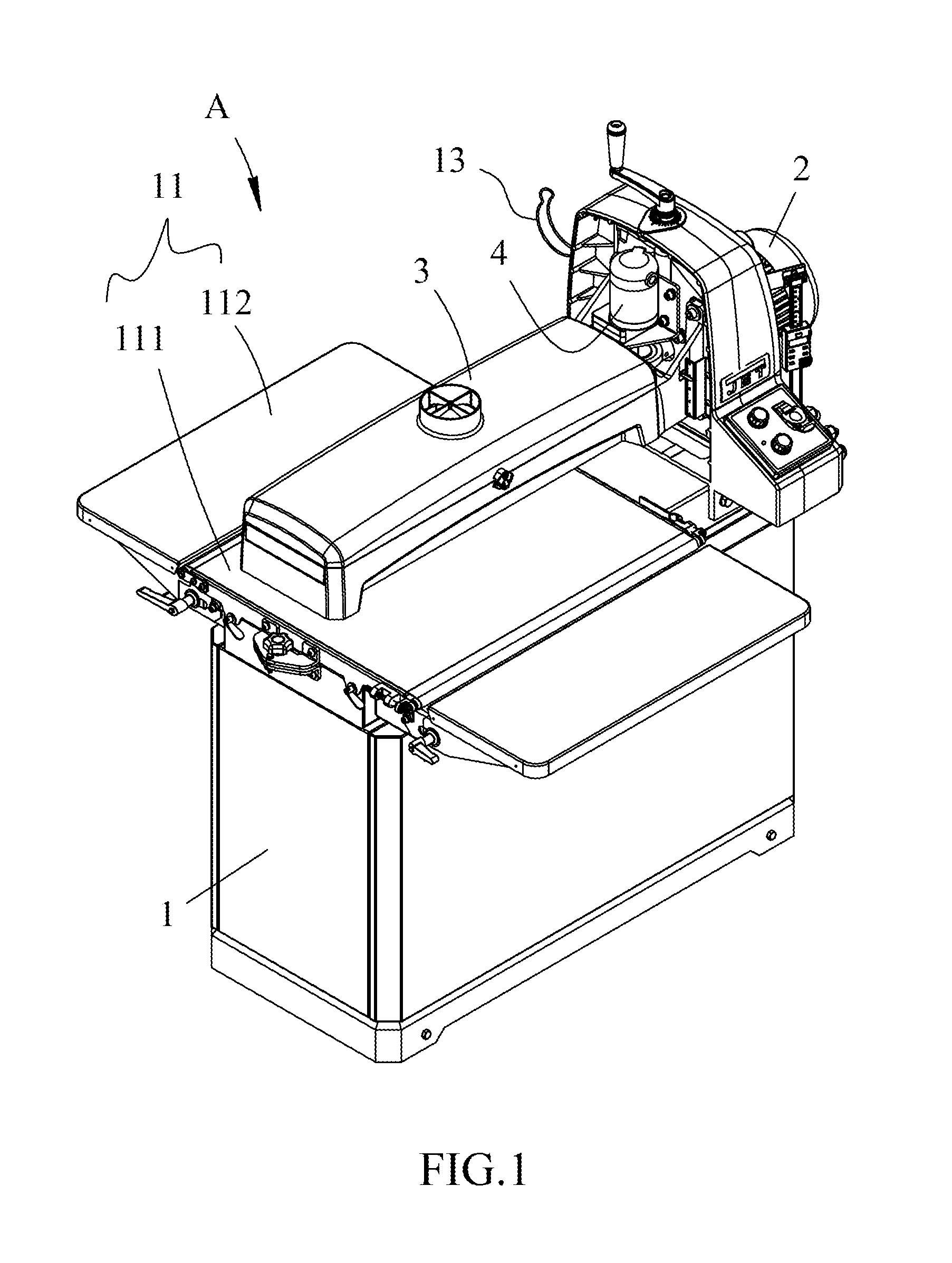
[0013] FIG. 1 is a perspective view to show the grinding machine of the present invention;
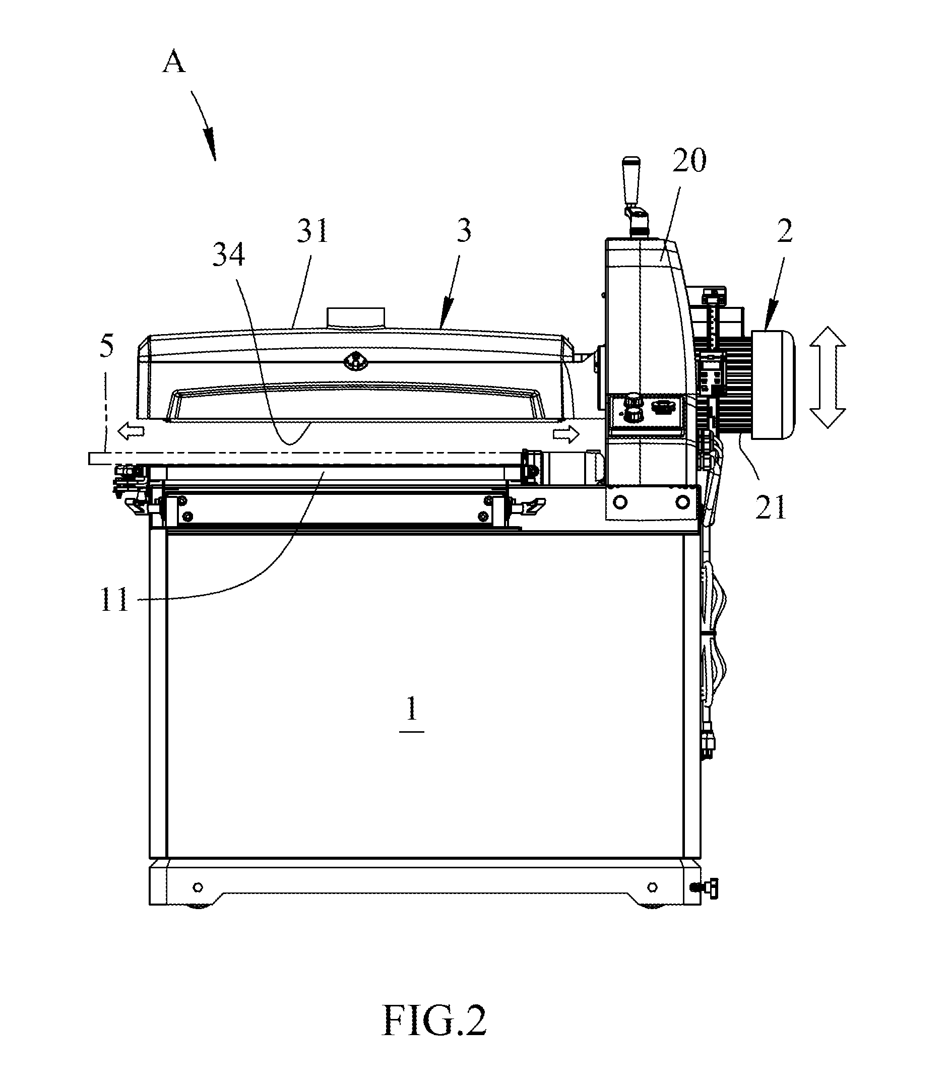
[0014] FIG. 2 is a side view to show the grinding machine of the present invention;
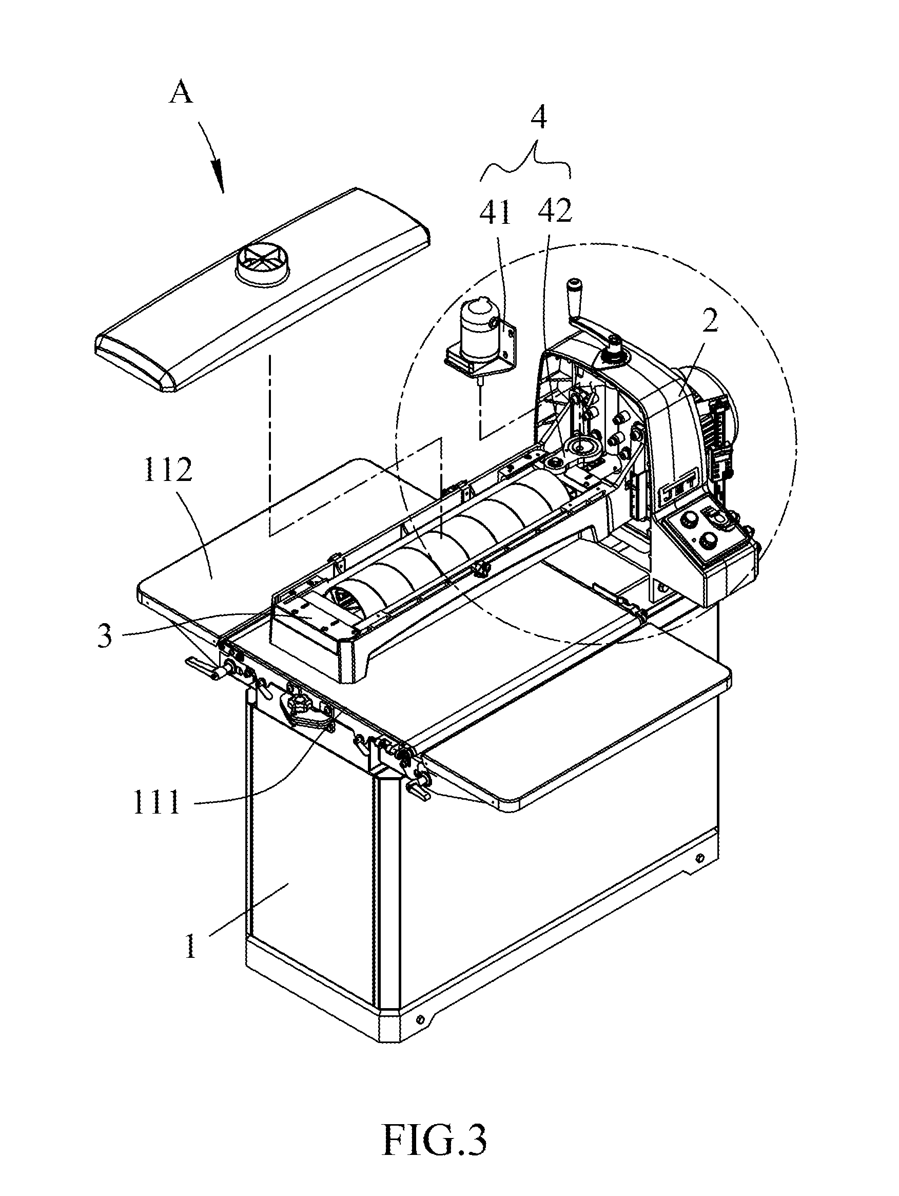
[0015] FIG. 3 is an exploded view of the grinding machine of the present invention;
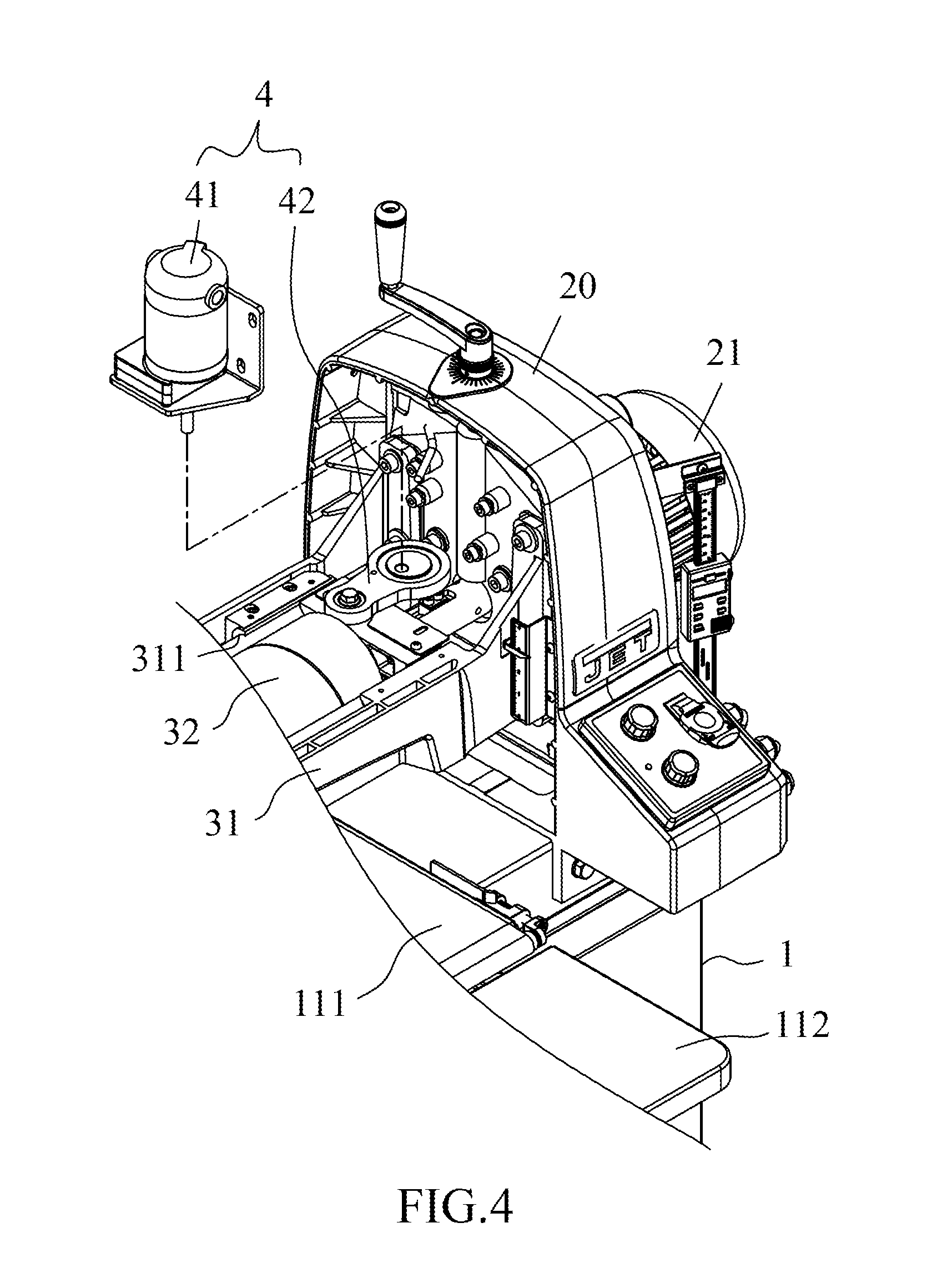
[0016] FIG. 4 is an enlarged view of a portion of the grinding machine of the present invention in FIG. 2;
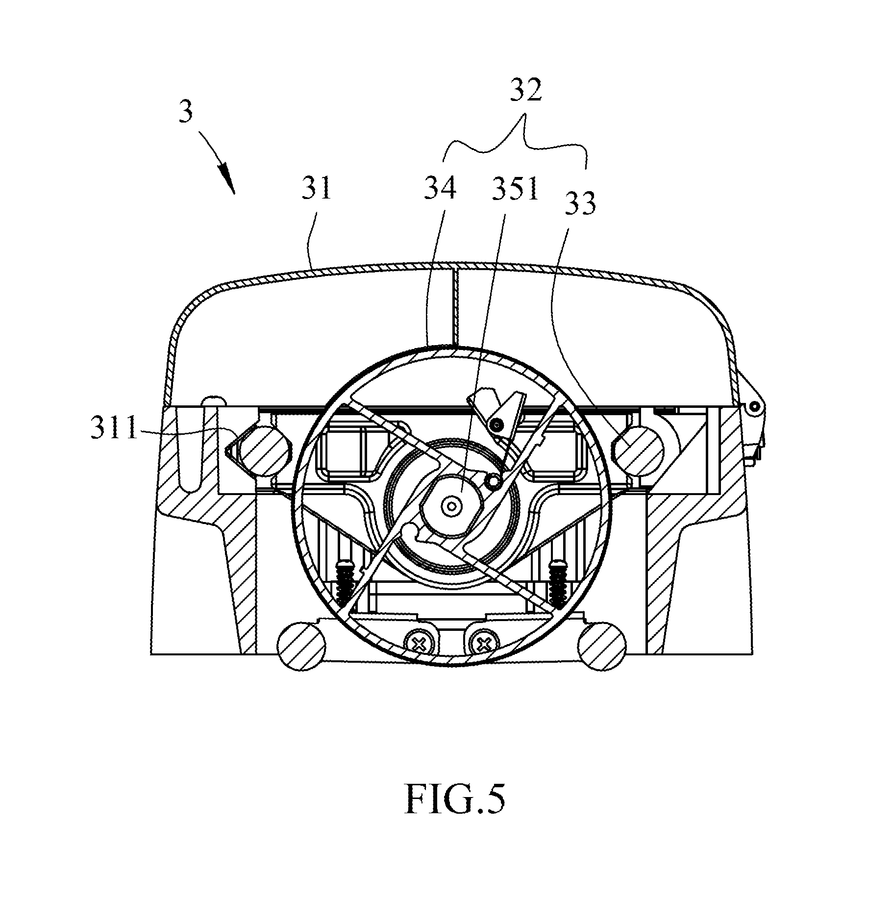
[0017] FIG. 5 shows the end cross sectional view of the transverse moving unit of the grinding machine of the present invention;
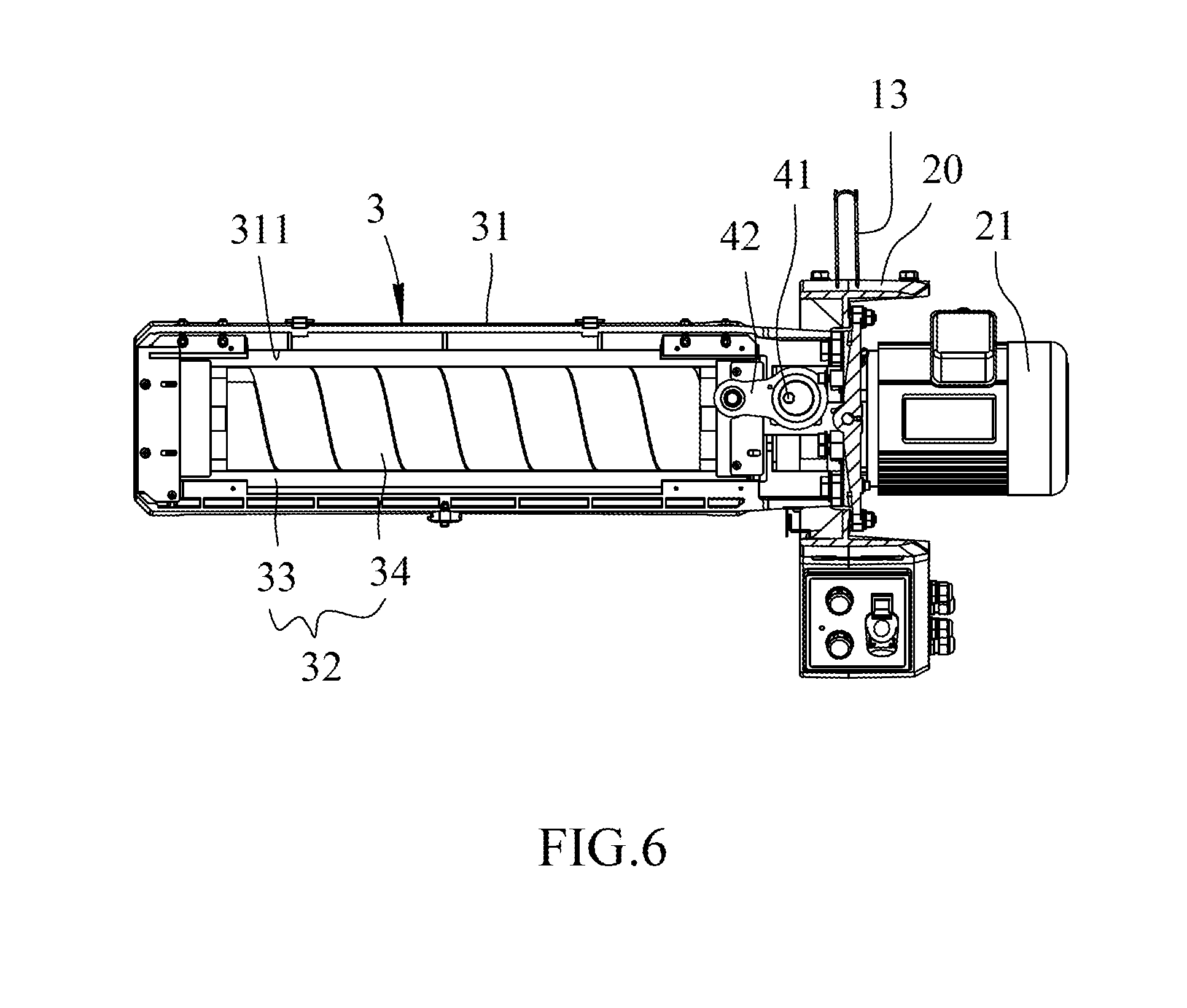
[0018] FIG. 6 is a top view of the transverse moving unit of the grinding machine of the present invention;
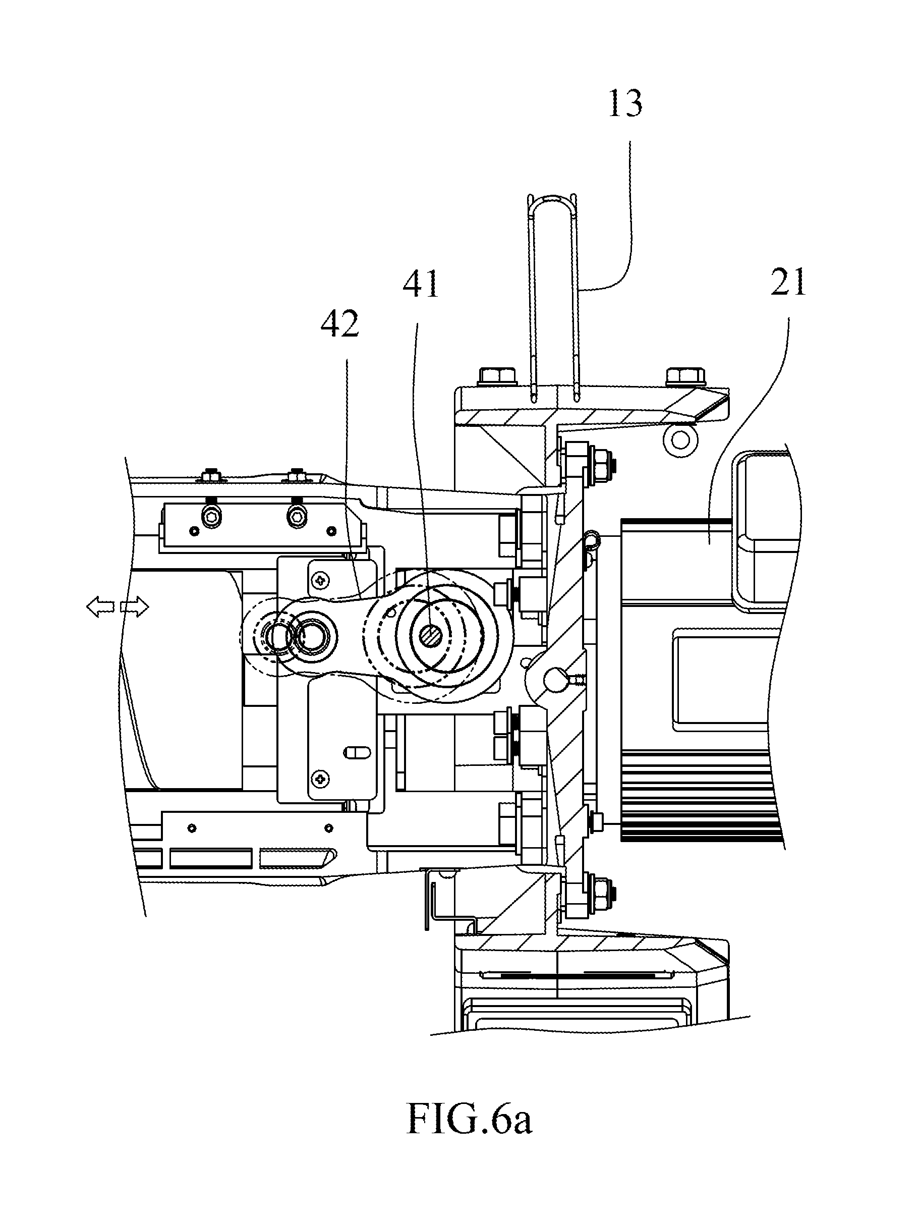
[0019] FIG. 6a shows the operational status of the transverse moving unit of the grinding machine of the present invention;
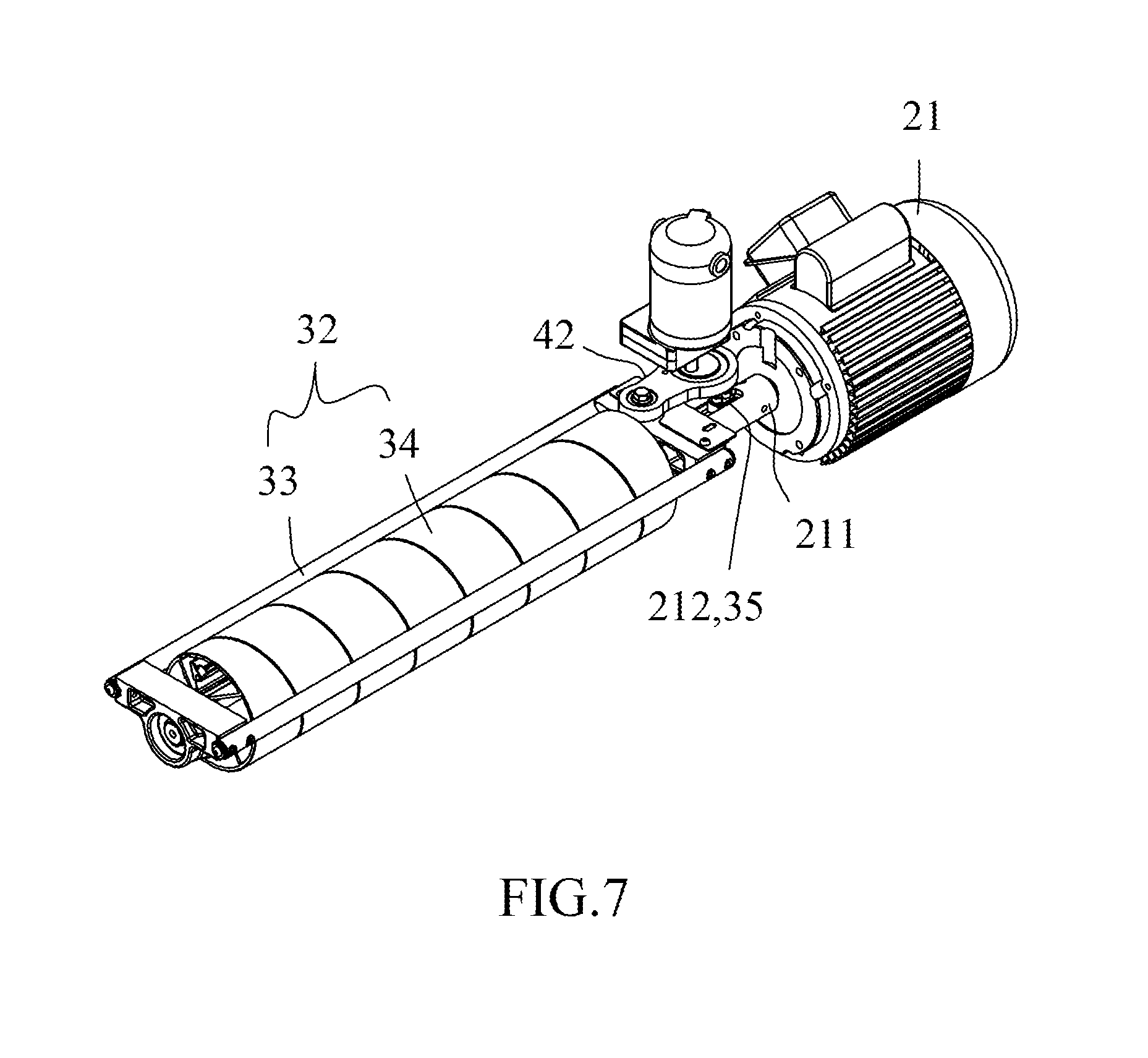
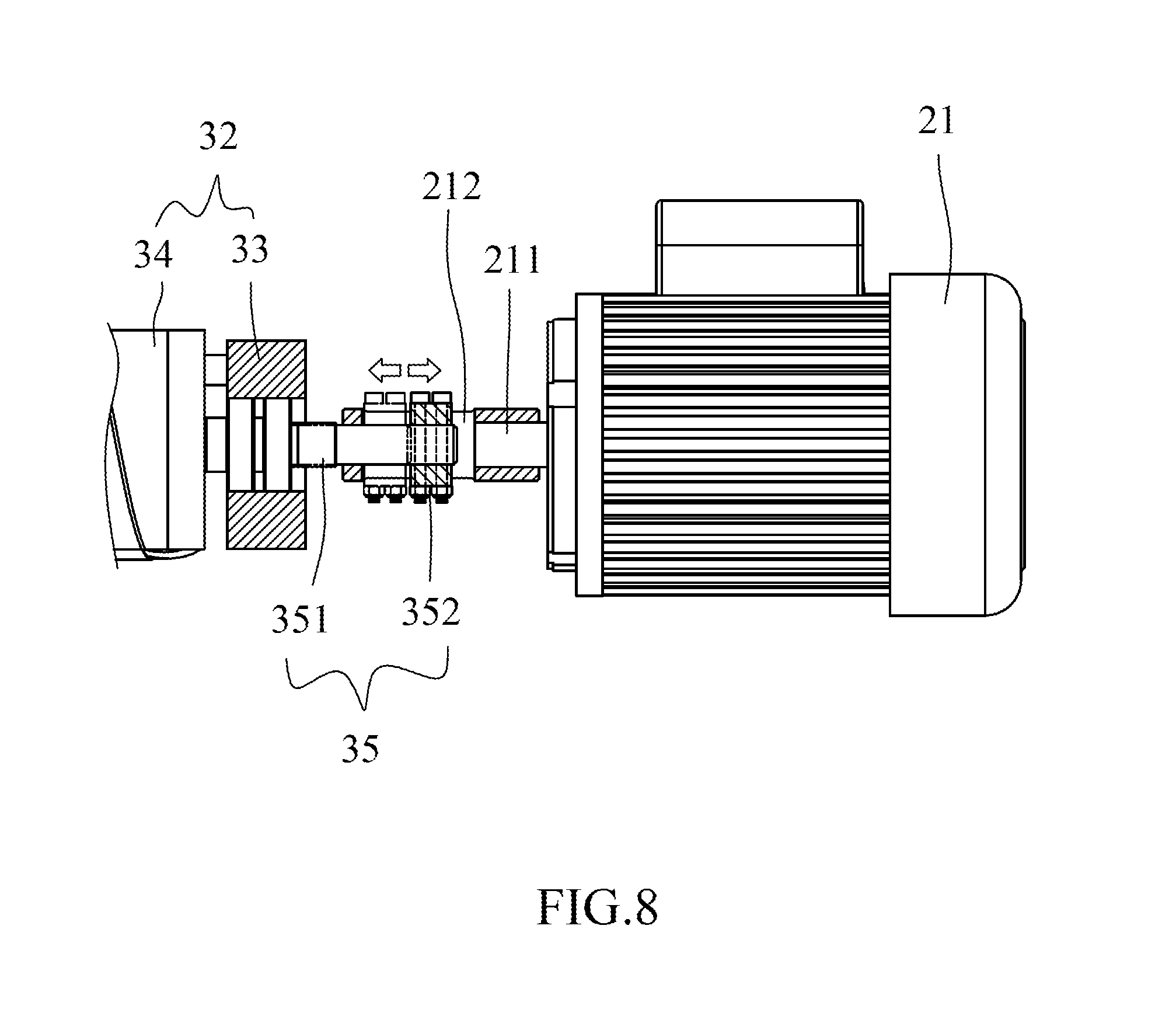
[0020] FIG. 7 shows that the grinding part of the transverse moving unit is connected to the first driving motor;
[0021] FIG. 8 shows another view of the grinding part of the transverse moving unit connected to the first driving motor, and
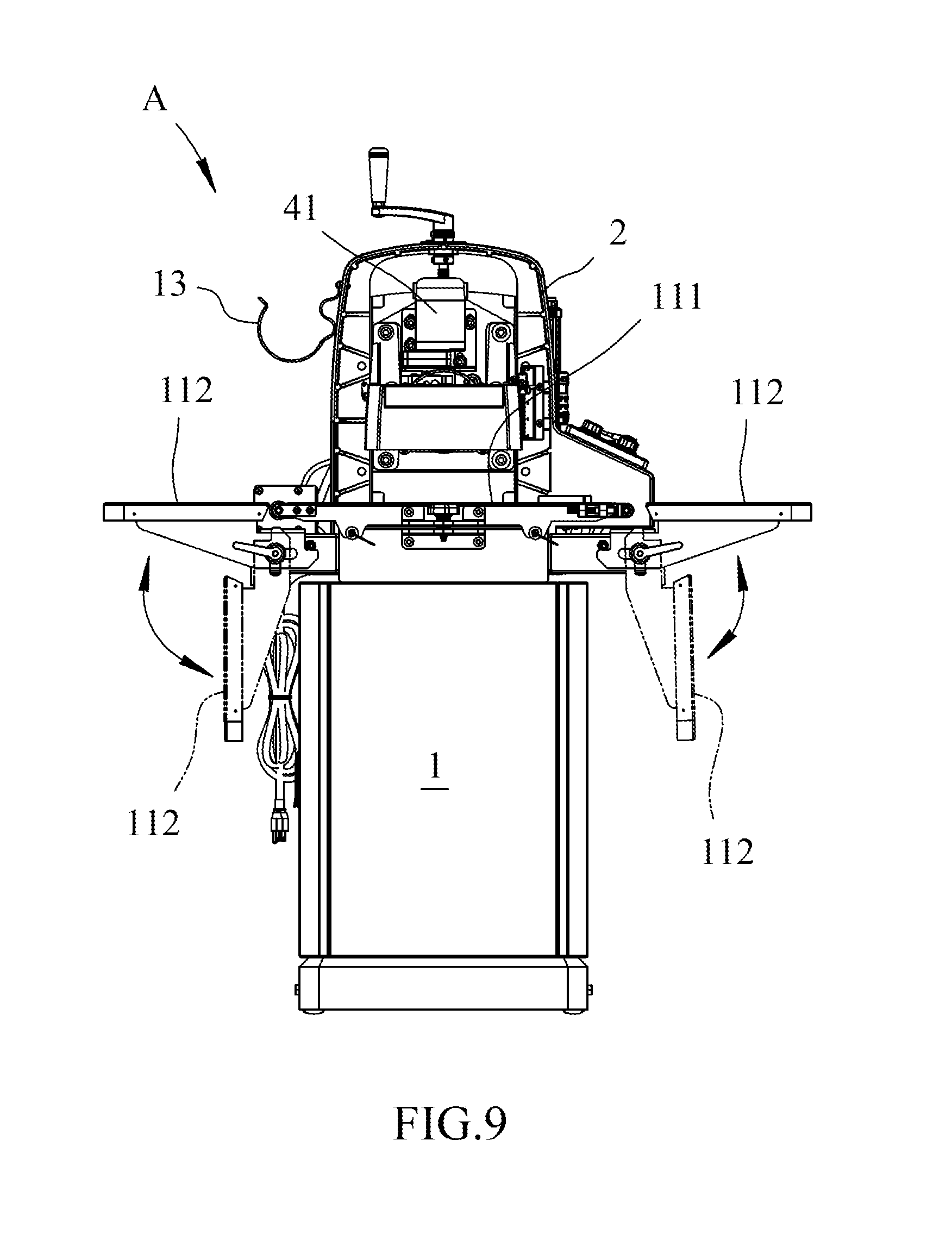
[0022] FIG. 9 shows that the secondary plate is foldable relative to the main plate.
DETAILED DESCRIPTION OF THE PREFERRED EMBODIMENT
[0023] Referring to FIGS. 1 to 8, the grinding machine "A" of the present invention is designed to grind a wider object 5, and comprises a base 1 which includes a plate 11 on the top thereof, and a movable device 12 is connected to the plate 11 as shown in FIG. 1. The movable device 12 moves the object on the plate. The plate 11 includes a main plate 111 and two secondary plates 112 which are respectively and pivotably connected to two sides of the main plate 111.
[0024] A driving unit 2 is connected to one end of the base 1 and has a frame 20 to which a first motor 21 is connected. The frame 20 includes a hook 22 on one side thereof as shown in FIG. 1 so as to hang other parts or tools. The frame 20 is able to adjust height of the first driving motor 21. The first motor 21 has a hollow shaft 211 which includes an oval hole 212 defined radially through the hollow shaft 211.
[0025] A grinding unit 3 is located across the top of the plate 11 and includes a body 31 and a grinding part 32. The grinding part 32 is slidably connected to a slot 311 of the body 31. The grinding part 32 includes a bracket 33 and a grinding wheel 34 which his located in the bracket 33. A shaft unit 35 is located in the oval hole 212 of the hollow shaft 211, and the shaft unit 35 includes a shaft 351 and two blocks 352 are respectively connected to the shaft 351.
[0026] A transverse moving unit 4 is connected to the grinding part 32 of the grinding unit 3 and includes a second driving motor 41 and a cam link 42. The cam link 42 is a cam link and connected between the second driving motor 41 and the grinding part 32. Specifically, the cam link 42 performs as a cam to which the second driving motor 41 drives. The transverse moving unit 4 is movable within the slot 311 of the body 31 to move the grinding part 32 transversely relative to the plate 11. It is noted that the second driving motor 41 is a variable-speed motor or a fixed-speed motor.
[0027] The second driving motor 41 drives the cam link 42, and the cam link 42 further drives the grinding part 32 to be movable in the slot 311 of the body 31 as shown in FIGS. 2 and 6a, so that the object having a larger width can be ground on the plate 11.
[0028] The second driving motor 41 is a variable-speed motor such that the speed that the transverse moving unit 4 moves transversely across the plate 11 can be controlled. When grinding a wider object 5 on the plate 11, the grinding part 32 can be controlled to be moved back and forth in the slot 311 by the transverse moving unit 4 to grind the wider object 5.
[0029] Furthermore, as shown in FIGS. 2 and 9, the two secondary plates 111 can be folded relative to the main plate 112 to save storage space. When the two secondary plates 111 are expanded, the wider object 5 can be well supported.
[0030] While we have shown and described the embodiment in accordance with the present invention, it should be clear to those skilled in the art that further embodiments may be made without departing from the scope of the present invention.
* * * * *
D00000
D00001
D00002
D00003
D00004
D00005
D00006
D00007
D00008
D00009
D00010
XML
uspto.report is an independent third-party trademark research tool that is not affiliated, endorsed, or sponsored by the United States Patent and Trademark Office (USPTO) or any other governmental organization. The information provided by uspto.report is based on publicly available data at the time of writing and is intended for informational purposes only.
While we strive to provide accurate and up-to-date information, we do not guarantee the accuracy, completeness, reliability, or suitability of the information displayed on this site. The use of this site is at your own risk. Any reliance you place on such information is therefore strictly at your own risk.
All official trademark data, including owner information, should be verified by visiting the official USPTO website at www.uspto.gov. This site is not intended to replace professional legal advice and should not be used as a substitute for consulting with a legal professional who is knowledgeable about trademark law.