Bubble Making Device
Kelly; Joshua C. ; et al.
U.S. patent application number 15/854159 was filed with the patent office on 2019-06-27 for bubble making device. The applicant listed for this patent is LightUpToys.com LLC. Invention is credited to Max Armendariz Lalama, Macaulay Bruton, Joshua C. Kelly.
| Application Number | 20190192989 15/854159 |
| Document ID | / |
| Family ID | 66949810 |
| Filed Date | 2019-06-27 |


View All Diagrams
| United States Patent Application | 20190192989 |
| Kind Code | A1 |
| Kelly; Joshua C. ; et al. | June 27, 2019 |
BUBBLE MAKING DEVICE
Abstract
The invention is a bubble making device for producing air bubbles from bubble solution, and contains a fan and a fan shroud for producing and channeling a stream of air through a dispensing ring into an ambient environment. Compression of a trigger or switch activates an electric circuit that energizes a motor that operates the fan and, in some embodiments, a pump. The pump delivers bubble solution to the dispensing ring, and a trigger or switch activated film producing mechanism attached to the air channel creates a film of bubble solution across the dispensing ring during interaction with an application bar. A separate internal sealed, waterproof, water resistant, and/or anti-corrosive container with external contacts serves as a battery compartment for containment of removably-insertable batteries. The invention can comprise of LED lights, a lighting system, sound producing device, sound producing system, speaker system and/or connection jack or device to connect to a smart device.
| Inventors: | Kelly; Joshua C.; (Sellersburg, IN) ; Armendariz Lalama; Max; (Georgetown, IN) ; Bruton; Macaulay; (Louiville, KY) | ||||||||||
| Applicant: |
|
||||||||||
|---|---|---|---|---|---|---|---|---|---|---|---|
| Family ID: | 66949810 | ||||||||||
| Appl. No.: | 15/854159 | ||||||||||
| Filed: | December 26, 2017 |
| Current U.S. Class: | 1/1 |
| Current CPC Class: | A63H 33/28 20130101; A63H 33/22 20130101; A63H 5/00 20130101 |
| International Class: | A63H 33/28 20060101 A63H033/28; A63H 5/00 20060101 A63H005/00 |
Claims
1. A bubble making device for producing bubbles from bubble solution, comprising: at least one housing with at least one handle; a battery compartment located on the side of the at least one handle of the at least one housing and electrical connection system; wherein said battery compartment is at least one of a sealed, waterproof, water resistant, and/or anti-corrosive container with external contacts that can hold at least one removably-insertable battery; wherein said at least one of a sealed, waterproof, water resistant, and/or anti-corrosive container has a cover that is attached and separated or opened by use of an attaching and removing device or fastener or screw to be tightened to close and loosened or removed to open; a trigger or switch that operates at least one mechanism and causes at least one electrical closure to be made; a motor that operates a fan and an electromechanical pump; said fan produces an air stream from the bubble making device to an ambient environment; a fan shroud containing an air channel that directs said air stream to the ambient environment; a movable dispensing ring with a dispensing aperture provided therein; at least one tube from the ambient or a bubble solution container for carrying bubble solution; said electromechanical pump comprising a mechanism for pumping bubble solution through said at least one tube, said at least one tube delivering bubble solution to said movable dispensing ring; and a film producing mechanism operated by said trigger or switch and pivotally attached to said air channel, with said movable dispensing ring that engages bubble solution on a stationary application bar and spreads bubble solution across said dispensing aperture, and said air stream passes through said dispensing aperture.
2. The bubble making device of claim 1 further comprising at least one of the following: LED lights and/or a lighting system; at least one of a sound producing device, a sound producing system, a speaker system and/or a connection jack or device to connect to a smart device; wherein said at least one of a sealed, waterproof, water resistant, and/or anti-corrosive container is designed so as to allow insertion and removal of batteries from the side of the at least one handle; wherein said stationary application bar is diagonally oriented; wherein said at least one housing in whole or in part has an animal, character, or creature style and/or is a molded shell of an animal, character, or creature; wherein a drip channel is attached to a threaded base, and is captured within said housing when said housing is assembled;
3. The bubble making device of claim 1, wherein said trigger is not present and said switch is a connection between the skin of the user of the bubble making device and the at least one handle.
4. The bubble making device of claim 2 wherein light is transmitted into a removably-attachable bubble solution container if present.
5. A bubble making device for producing bubbles from bubble solution, comprising: at least one housing; a battery compartment and electrical connection system; wherein said battery compartment is at least one of a sealed, waterproof, water resistant, and/or anti-corrosive container with external contacts that can hold at least one removably-insertable battery; wherein said at least one of a sealed, waterproof, water resistant, and/or anti-corrosive container has a cover that is attached and separated or opened by use of an attaching and removing device or fastener or screw to be tightened to close and loosened or removed to open; a trigger or switch that operates at least one mechanism and causes at least one electrical closure to be made; a motor that operates a fan; said fan produces an air stream from the bubble making device to an ambient environment; a fan shroud containing an air channel that directs said air stream to the ambient environment; a dispensing ring with a dispensing aperture provided therein; said at least one mechanism is a mechanical pump that is operated by said trigger or switch; at least one tube from the ambient or a bubble solution container for carrying bubble solution; said mechanical pump comprising a mechanism for pumping bubble solution through said at least one tube, said at least one tube delivering bubble solution to said dispensing ring; and a film producing mechanism operated by said trigger or switch and pivotally attached to said air channel, with an application bar that engages bubble solution on said dispensing ring and spreads bubble solution across said dispensing aperture, and said air stream passes through said dispensing aperture.
6. The bubble making device of claim 5, further comprising an electromechanical sequence whereby: two displacement regimes are sequentially activated by the displacement of said trigger or switch, and the entire displacement range of said trigger or switch is divided into said two displacement regimes, with a first displacement regime occurring when said trigger or switch is first displaced by squeezing said trigger or switch, and a second displacement regime occurring after said first displacement regime, and said second displacement regime continues as said trigger or switch is increasingly displaced by continued squeezing until said trigger or switch is maximally displaced; the closure of an electrical switch is caused by a small initial displacement of said trigger or switch and remains closed during the said entire displacement range of motion of said trigger or switch; and said film producing mechanism is activated during said first displacement regime and said mechanical pump is activated during said second displacement period.
7. The bubble making device of claim 6, further comprising an operation whereby said film producing mechanism is operated during said first displacement regime independently of said mechanical pump and said mechanical pump is operated during said second displacement regime independently of said film producing mechanism.
8. The bubble making device of claim 5, further comprising at least one of the following: LED lights and/or a lighting system; at least one of a sound producing device, a sound producing system, a speaker system and/or a connection jack or device to connect to a smart device; at least one of a sealed, waterproof, water resistant, and/or anti-corrosive container is designed so as to allow insertion and removal of batteries from a side of a handle; said battery compartment is located above said fan shroud; at least one of a sealed, waterproof, water resistant, and/or anti-corrosive container is designed so as to allow insertion and removal of batteries from the top and/or side; said application bar is diagonally oriented; at least one housing in whole or in part has an animal, character, or creature style and/or is a molded shell of an animal, character, or creature; a drip channel is attached to a threaded base, and is captured within said housing when said housing is assembled;
9. The bubble making device of claim 8, wherein light is transmitted into a removably-attachable bubble solution container;
10. A bubble making device for producing bubbles from bubble solution, comprising: at least one housing with at least one handle; a battery compartment located on the side of the at least one handle of the at least one housing and electrical connection system; wherein said battery compartment is at least one of a sealed, waterproof, water resistant, and/or anti-corrosive container with external contacts that can hold at least one removably-insertable battery; wherein said at least one of a sealed, waterproof, water resistant, and/or anti-corrosive container has a cover that is attached and separated or opened by use of an attaching and removing device or fastener or screw to be tightened to close and loosened or removed to open; a trigger or switch that operates at least one mechanism and causes at least one electrical closure to be made; a motor that operates a fan; said fan produces an air stream from the bubble making device to an ambient environment; a fan shroud containing an air channel that directs said air stream to the ambient environment; a moveable dispensing ring with a dispensing aperture provided therein; said at least one mechanism is a mechanical pump that is operated by said trigger or switch; at least one tube from the ambient or a bubble solution container for carrying bubble solution; said mechanical pump comprising a mechanism for pumping bubble solution through said at least one tube, said at least one tube delivering bubble solution to said moveable dispensing ring; and a film producing mechanism operated by said trigger or switch and pivotally attached to said air channel, with a stationary application bar that engages bubble solution on said moveable dispensing ring and spreads bubble solution across said dispensing aperture, and said air stream passes through said dispensing aperture.
11. The bubble making device of claim 10, further comprising an electromechanical sequence whereby: two displacement regimes are sequentially activated by the displacement of said trigger or switch, and the entire displacement range of said trigger or switch is divided into said two displacement regimes, with a first displacement regime occurring when said trigger or switch is first displaced by squeezing said trigger or switch, and a second displacement regime occurring after said first displacement regime, and said second displacement regime continues as said trigger or switch is increasingly displaced by continued squeezing until said trigger or switch is maximally displaced; the closure of an electrical switch is caused by a small initial displacement of said trigger or switch and remains closed during the said entire displacement range of motion of said trigger or switch; and said film producing mechanism is activated during said first displacement regime and said mechanical pump is activated during said second displacement period.
12. The bubble making device of claim 11, further comprising an operation whereby said film producing mechanism is operated during said first displacement regime independently of said mechanical pump and said mechanical pump is operated during said second displacement regime independently of said film producing mechanism.
13. The bubble making device of claim 10, further comprising LED lights and/or a lighting system.
14. The bubble making device of claim 10, further comprising at least one of a sound producing device, a sound producing system, a speaker system and/or a connection jack or device to connect to a smart device.
15. The bubble making device of claim 10, wherein said at least one of a sealed, waterproof, water resistant, and/or anti-corrosive container is designed so as to allow insertion and removal of batteries from a side of at least one handle.
16. The bubble making device of claim 10, wherein said stationary application bar is diagonally oriented.
17. The bubble making device of claim 10, wherein said at least one housing in whole or in part has an animal, character, or creature style and/or is a molded shell of an animal, character, or creature.
18. The bubble making device of claim 10, wherein a drip channel is attached to a threaded base, and is captured within said housing when said housing is assembled.
19. The bubble making device of claim 13, wherein light is transmitted into a removably-attachable bubble solution container.
Description
CROSS-REFERENCE TO RELATED APPLICATIONS
[0001] This is a continuation in part and claims priority to and the benefit of application Ser. No. 15/599,351 filed on May 18, 2017 which application is a continuation-in-part of U.S. Nonprovisional patent application Ser. No. 14/204,285, filed Mar. 11, 2014, which claims priority to U.S. Provisional Patent Application No. 61/831,143, filed Jun. 5, 2013.
BACKGROUND OF THE INVENTION
[0002] The present invention relates generally to toys, and more specifically to a battery powered toy device that produces bubbles from a liquid solution.
[0003] There have been many bubble toys over the years that operate in various ways. However, most bubble toys are hand-held rings that are either blown through or hand waved by the user to produce a small amount of bubbles. It is desired to provide a toy that produces a steady stream of bubbles and a safe entertainment for a child. The present invention is an improved battery powered toy device that produces bubbles from a liquid solution. In the present invention, the battery compartment can be a sealed container with external contacts, which prevents fluid from penetrating the interior of such container and the battery. The present invention also has an improved access to the battery compartment interior. Additionally, the present invention improves the quality of play pattern with the addition of lights and/or sounds in a cost-effective manner.
SUMMARY OF THE INVENTION
[0004] The present invention is a bubble making device that produces bubbles by pulling a trigger or switch, which causes power to be applied to an electrical circuit and/or system that activates a pump, or pump mechanism, and a fan, or fan mechanism. In one embodiment, the pump can be electromechanical and driven by an electric motor. In other embodiments, the pump can be purely mechanical and activated by a trigger or switch mechanism in a similar manner as mechanical water pistols are trigger, or switch activated.
[0005] One embodiment of the present invention has a separate sealed internal battery compartment with external (i.e., exteriorly connected) electrical contacts within the bubble making device. If the pump is electromechanical and driven by an electric motor, such separate sealed internal battery compartment with external electrical contacts provides the source of power that drives an electrical motor, which operates the pump and the fan that produces a moving stream of air, or air stream that flows through an air channel within the fan shroud. Such moving stream of air originates as stationary or near-stationary ambient air outside the housing of the invention, which enters the housing through holes, and is subsequently accelerated by the fan to produce the moving stream of air. The air channel within the fan shroud directs the air stream towards a secondary opening of the bubble making device housing through a generally circular-shaped dispensing aperture defined within a movable dispensing ring, which directs the air stream back to the ambient.
[0006] The sealed battery compartment of the present invention can have a cover that is attached, and separated or opened by the use of an attaching and removing device, fastener or screw, which is to be tightened to close, and loosened or removed to open. The sealed battery compartment is designed to allow insertion and removal of batteries from the side of a handle on said compartment. The sealed battery compartment can also be located above the fan shroud on the top of the bubble making device. If the sealed battery compartment is located above the fan shroud on the top of the bubble making device, the batteries can be inserted and removed from the top and/or side of said compartment.
[0007] In one embodiment of the present invention the moveable dispensing ring defines a dispensing surface upon which liquid bubble solution adheres to the moveable dispensing ring across a dispensing aperture. The liquid bubble solution utilized in the present embodiment may be obtained or sold separately, or in conjunction with the bubble making device in the same packaging or box. The bubble making device may have threads defined in the walls of a primary opening to which a typical, commercially sold bubble solution container may be removeably-attached by mating said threads in the walls of the primary opening with complimentary threads defined on the outside walls of said typical, commercially sold bubble solution container. The bubble making device pump, whether electromechanical or mechanical, causes movement of the bubble solution through at least one tube, which causes the bubble solution to be delivered to the moveable dispensing ring, or stationary dispensing ring in another embodiment. Pulling the trigger or switch of the present invention activates the electromechanical pump, the fan, and initiates an up-and-down motion of a film producing mechanism. The film producing mechanism moves the dispensing ring in an up-and-down motion across a stationary application bar, which can be horizontally or diagonally oriented, thus sweeping a layer of bubble solution over the dispensing aperture of the moveable dispensing ring, or the stationary dispensing ring in another embodiment. At the same time that the bubble solution is swept over the dispensing ring, the air stream generated by the fan travels through the air channel within the fan shroud and expels one or more bubbles from the secondary opening of the bubble making device.
[0008] If excess bubble solution accumulates on the moveable dispensing ring, a drip flange located at the base of the moveable dispensing ring directs the excess bubble solution downward into a drip channel attached to a threaded base. The drip channel can direct the excess bubble solution into the ambient or a bubble container when a bubble container is so attached. It is preferable for the drip channel to be funnel-shaped, being wider at the top facing the dispensing aperture and narrower at the bottom.
[0009] In embodiments of the present invention employing a mechanical pump, all the basic components of the embodiments using an electromechanical pump are present. Therefore, only the added features need be explained and are discussed below.
[0010] When employing a mechanical pump, there can be an electromechanical sequence whereby two displacement regimes are sequentially activated by the displacement of the trigger or switch, and the entire displacement range of the trigger or switch is divided into two displacement regimes, with a first displacement regime occurring when the trigger or switch is first displaced by squeezing the trigger or switch, and a second displacement regime occurring after the first displacement regime, which continues as the trigger or switch is increasingly displaced by continued squeezing until the trigger or switch is maximally displaced. When the trigger or switch is first squeezed, there can be a closure of an electrical switch caused by a small initial displacement of the trigger or switch, and the switch can remain closed during the entire displacement range of motion of the trigger or switch. The film producing mechanism can be activated during the first displacement regime and the mechanical pump can be activated during the second displacement regime. The ability to activate the film producing mechanism during the first displacement regime and the mechanical pump during the second displacement regime enables a very useful feature whereby the film producing mechanism can be operated during the first displacement regime independently of the mechanical pump and the mechanical pump can be operated during said second displacement regime independently of the film producing mechanism. Such independent operation can be utilized by squeezing the trigger or switch all the way, partially releasing the trigger or switch, re-squeezing the trigger or switch several times in order to pump bubble solution to the dispensing ring, releasing the trigger or switch all the way, and partially operating the trigger or switch so as to only actuate the film producing mechanism. During the aforementioned independent operation sequence, the fan can produce an air stream to continue to blow bubbles so long as there is sufficient bubble solution on the dispensing ring. When the bubble solution supply is exhausted, the trigger or switch can be depressed all the way to pump more bubble solution on the dispensing ring.
[0011] In embodiments employing a mechanical pump, such as the embodiment(s) just described above, one embodiment can employ a movable dispensing ring on a film producing mechanism that is pivotally attached to the fan shroud, and a stationary application bar can be attached to a drip channel. Another embodiment can employ a moving application bar on a film producing mechanism that is pivotally attached to the fan shroud, and a stationary dispensing ring can be positioned such that the center of the air stream is directed through the dispensing aperture.
[0012] In one embodiment, the bubble making device of the present invention may also have one or more light-emitting diode (LED) lights or lighting system(s) that are activated by manually pulling the trigger or switch, or by a switch. The bubble making device of the present invention may also have a sound-producing device that is also activated by pulling the trigger or switch, or by a switch. Such LED lights and sound-producing features taken together or individually increase the overall enjoyment of the bubble making device and make the bubble making device more appealing to children.
[0013] Further appeal can be realized when light can be transmitted into the removably-attachable container that can contain bubble solution, which can occur when a flexible or rigid light pipe that can be made from any material that can transmit light is utilized.
[0014] The bubble making device housing can, in whole or in part, have an animal, character, or creature style and/or is a molded shell of an animal, character, or creature.
[0015] In at least one embodiment, the bubble making device is trigger or switch free.
[0016] Although preferred embodiments of the present invention have been described it will be understood by those skilled in the art that the present invention should not be limited to the described preferred embodiments. Rather, various changes and modifications can be made within the spirit and scope of the present invention.
BRIEF DESCRIPTION OF THE SEVERAL VIEWS OF THE DRAWING
[0017] The drawings constitute a part of this specification and include exemplary embodiments to the invention, which may be embodied in various forms. It is to be understood that in some instances various aspects of the invention may be shown exaggerated or enlarged to facilitate an understanding of the invention.
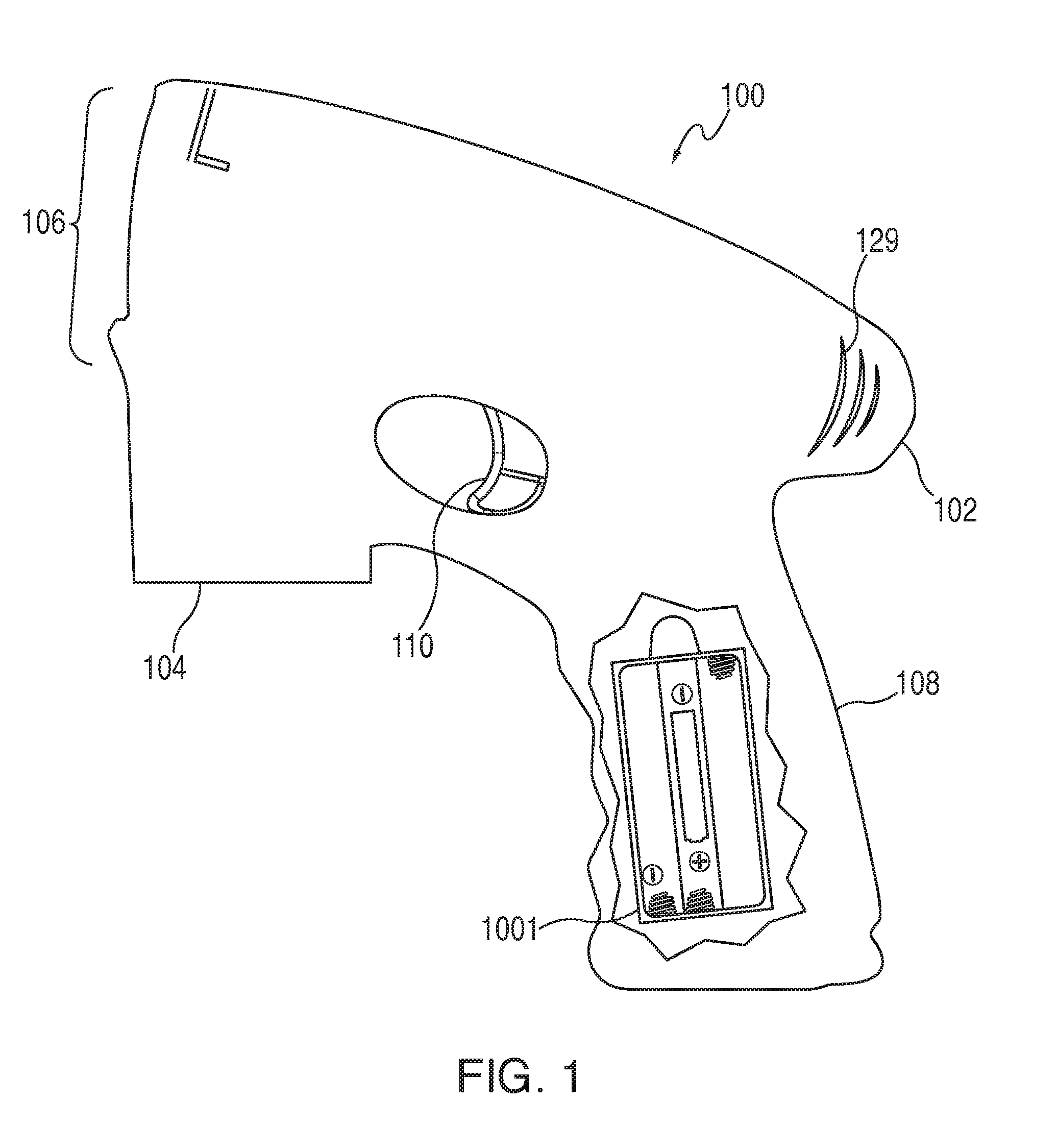
[0018] FIG. 1 is a side view of the bubble making device of the present invention.
[0019] FIG. 2 is a perspective view of the bubble making device of the present invention, showing the inner workings of the basic parts of the bubble making device of the present invention.
[0020] FIG. 3 is a detailed view showing the trigger or switch-handle subassembly of the bubble making device of the present invention when the trigger or switch is depressed.
[0021] FIG. 4 is a detailed view showing the trigger or switch-handle subassembly of the bubble making device of the present invention when the trigger or switch is not depressed.
[0022] FIG. 5 shows a front view of the bubble toy with the film producing mechanism shown in a "down" position.
[0023] FIG. 6 shows a front view of the bubble toy with the film producing mechanism shown in an "up" position.
[0024] FIG. 7 is a schematic diagram of a power circuit for the bubble making device of the present invention.
[0025] FIG. 8 shows an alternate embodiment of a battery compartment of one embodiment of the present invention.
[0026] FIG. 9 shows the mechanical linkage between the trigger or switch and the film producing mechanism of one embodiment of the present invention.
[0027] FIG. 10 shows a perspective view of an alternate embodiment with an animal, character, creature or other styled or molded into the shell or outside or housing.
[0028] FIG. 11 shows a side view schematic representation for a moving application bar and stationary dispensing ring embodiment, showing the trigger or switch, the film producing mechanism, and the mechanical pump.
[0029] FIG. 12 shows the extension and details of the two-regime slot.
[0030] FIG. 13 shows three key positions in the two-regime slot.
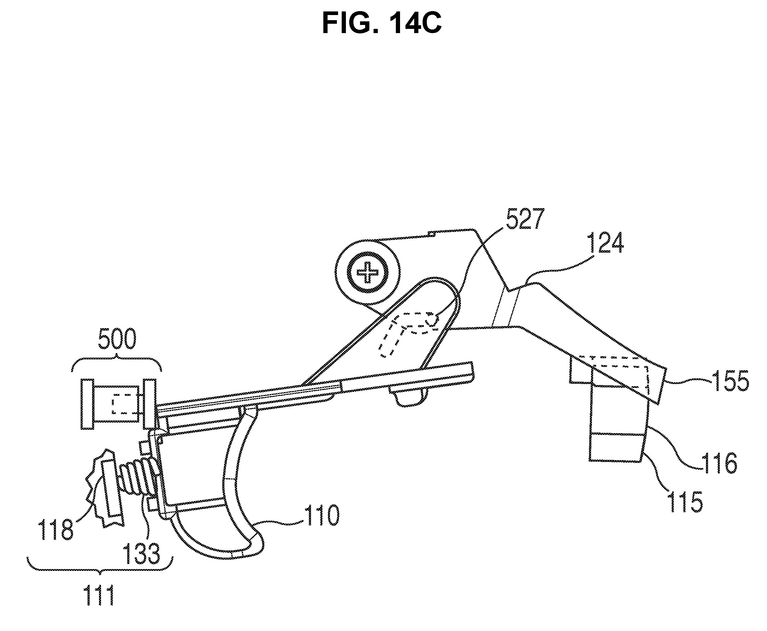
[0031] FIGS. 14A, 14B, and 14C each show a side view of a schematic representation of one of three key trigger or switch positions in the two-regime slot for a moving application bar and stationary dispensing ring embodiment, including of the trigger or switch, the film producing mechanism, and the mechanical pump in each one of the three trigger or switch positions.
[0032] FIGS. 15A, 15B, and 15 C each show a side view of a schematic representation of one of the three key trigger or switch positions in the two-regime slot for a movable dispensing ring and stationary application bar embodiment, including of the trigger or switch, the film producing mechanism, and the mechanical pump in each one of the three trigger or switch positions.
[0033] FIG. 16 shows a side view of the out shell styled as a gun.
[0034] FIG. 17 shows a perspective view with internal components of one embodiment.
[0035] FIG. 18 shows a side view of a light and light pipe for illuminating bubble solution.
[0036] FIG. 19 shows one embodiment of the the claimed invention with the sealed container/battery oriented above the fan shroud.
[0037] FIG. 20 shows one embodiment of the claimed invention with a diagonal orientation of the application bar.
DETAILED DESCRIPTION OF THE INVENTION
[0038] Detailed descriptions of particular embodiment are provided herein. It is to be understood, however, that the present invention may be embodied in various forms. Therefore, specific details disclosed herein are not to be interpreted as limiting, but rather as a basis for the claims and as a representative basis for teaching one skilled in the art to employ the present invention in virtually any appropriately detailed system, structure or manner.
[0039] FIG. 1 shows a side view of the bubble making device 100. The bubble making device 100 has a bubble making device housing 102, a primary opening 104 with threads defined in walls of the primary opening 104, and a secondary opening 106 from which air bubbles will emanate. The bubble making device 100 also has a handle 108 and a trigger or switch mechanism or trigger or switch 110. In this embodiment, the handle 108 may include a battery compartment 136 (labeled in FIG. 2), which can be in the form of a sealed container, and is shown with a transparent door 1001. Other than the door 1001, the bubble making device housing 102 shown in FIG. 1 is opaque though it can be any color. Also, although the door 1001 is shown as being transparent in the figures, it can also be opaque or partially transparent and/or partially opaque, or any color.
[0040] FIG. 2 shows a side perspective view of the bubble making device 100, in which bubble making device housing 102 is transparent. In FIG. 2, delivery tube 112 extends downward for receiving bubble solution from the exterior, and is usually from a reservoir source or container through the primary opening 104 which may have a mechanism for attaching to opening 103, and, when a separate (not permanently attached) removably-attachable bubble solution container 170 (not claimed as part of the invention bubble making device 100 herein, but shown in FIGS. 2 and 10) is attached to opening 104 using mechanism for attaching to opening 103. The delivery tube 112 extends into the bubble solution from an exterior source, which is usually from an exterior reservoir source or container. The bubble making device 100 has the secondary opening 106 and a moveable dispensing ring 114 with a dispensing aperture 116. The dispensing aperture 116 provides a path for egress of air and of soap bubbles.
[0041] Referring to FIG. 7, a power circuit 8 provides electrical power to activate mechanisms of the bubble making device 100, including an electric motor 121 for operating an electromechanical pump 120 and a fan 122. The fan 122 has a fan shroud 123 that helps to direct air towards the secondary opening 106 and the dispensing aperture 116 of moveable dispensing ring 114. The delivery tube 112 extends from the electromechanical pump 120 via the electromechanical pump input 156 to bubble solution from the exterior, which usually comes from a reservoir source or container (removably-attachable bubble solution container 170 shown in FIGS. 2 and 10) through the primary opening 104 to provide a convenient source of bubble solution to the electromechanical pump input 156 of the electromechanical pump 120.
[0042] Many types of electrically driven pumps may be used for the electromechanical pump 120, such as a gear pump, a screw pump or a plunger pump or other positive displacement pump. In the electromechanical pump 120 shown in FIG. 2, rotation is caused by the drive gear 119. The electromechanical pump 120 receives the bubble solution at the electromechanical pump input 156 and outputs the bubble solution at the electromechanical pump output 158 of the electromechanical pump 120 at a sufficiently increased pressure to deliver bubble solution to the dispensing ring 114.
[0043] Bubble solution exits the electromechanical pump 120 through the electromechanical pump output 158 and is transported through a feed tube 125 and exits the feed tube 125 near the moveable dispensing ring 114. The fan 122 produces moving air that is expelled through an air channel 126 defined in the fan shroud 123 and subsequently exits through the dispensing aperture 116. Inlet air is provided to the fan 122 through a hole and/or series of holes in fan shroud 129 at the top of the fan shroud 123. A film producing mechanism 124 is pivotally attached to the air channel 126.
[0044] The film producing mechanism 124 moves the moveable dispensing ring 114 in an up-and-down motion next to the stationary application bar 154 to deposit a thin film of bubble solution on the moveable dispensing ring 114. The film producing mechanism 124 is mechanically linked to the trigger or switch 110 such that pulling the trigger or switch 110 raises the film producing mechanism 124 and releasing the trigger or switch 110 lowers the film producing mechanism 124. In other embodiments, pulling the trigger or switch 110 lowers the film producing mechanism 124 and releasing the trigger or switch 110 raises the film producing mechanism 124.
[0045] When air moves through the air channel 126 and past the moveable dispensing ring 114, the flowing air creates a bubble or many bubbles that float away from the bubble making device 100. If there is any excess bubble solution on the moveable dispensing ring 114, this solution drips down a drip flange 128, into a drip channel 130 attached to or defined within an interior of the bubble making device housing 102, and eventually returns to primary opening 104 which can lead to the ambient, any type of reservoir, source of liquid, or a removably-attachable bubble solution container (not shown).
[0046] FIGS. 3 and 4 show a trigger or switch/handle subassembly for the bubble making device 100 of the present invention. As shown in FIGS. 3 and 4, the trigger or switch 110 is attached to an electrically conductive metal spring 133, which is further attached to and fed by a spring feed wire 113. When the trigger or switch 110 is being pulled or depressed, as shown in FIG. 3, the switch 111 (depicted schematically in FIG. 7) is in a closed position, thus conducting electricity. The switch 111 is formed by the metal spring 133 and the contact zone 118 on electric motor 121, thus utilizing the electrically conductive metal casing of the electric motor 121 as one of the electrical contacts of the switch 111. FIG. 4 shows the trigger or switch/handle subassembly when trigger or switch 110 is not being pulled or depressed, and thus the switch 111 is in the open position because the metal spring 133 and the contact zone 118 on electric motor 121 are not in contact with each other, and are not conducting electricity.
[0047] FIGS. 5 and 6 show and end view looking into where the bubbles exit the bubble making device 100. FIG. 5 shows the invention with the film producing mechanism 124 (shown in FIGS. 2, 9, and 17) in a lower position when the trigger or switch 110 is not being pulled. FIG. 6 shows the invention with the film producing mechanism 124 (shown in FIGS. 2, 9, and 17) in a raised position when the trigger or switch 110 is being pulled. In this embodiment the stationary application bar 154 is attached to the drip channel 130. When the trigger or switch 110 is not pulled as shown in FIG. 5, the moveable dispensing ring 114 of the film producing mechanism 124 (shown in FIGS. 2, 9, and 17) rests at or near the bottom of its travel, and thus the stationary application bar 154 rests across and touches the top of the moveable dispensing ring 114. When the trigger or switch 110 is pulled all the way as shown in FIG. 6, the moveable dispensing ring 114 of the film producing mechanism 124 (shown in FIGS. 2, 9, and 17) rests at or near the top of its travel, and the stationary application bar 154 rests across and touches the bottom of the moveable dispensing ring 114, thus spreading a thin film of a bubble producing liquid across the dispensing aperture 116 when the moveable dispensing ring 114 executes a full range of motion from the bottom to the top, which causes the stationary application bar 154 to smear bubble producing liquid from the top to the bottom of the moveable dispensing ring 114.
[0048] FIG. 9 shows a schematic side view of the film producing mechanism 124, which is operated by the trigger or switch 110. The trigger or switch 110 is rigidly attached to or integrally formed with a flat plate 142. Extension 144 is attached to or integrally formed with the flat plate 142 and extends upward (at an angle in this embodiment) from the flat plate 142. Extension 144 includes elongated slot 148. Horizontal post 146, which extends perpendicularly out of the plane of the drawing in FIG. 9, fits in the elongated slot 148, and thus moves up or down as the extension 144 moves left or right with the trigger or switch 110 being pulled or released.
[0049] The film producing mechanism 124 is pivotally connected to the air channel 126. A first end 150 of the film producing mechanism 124 has a U-shaped portion which is attached to the air channel 126 using fastener 151 (shown in FIG. 2) which projects from the air channel 126. Other methods of connection are possible, and the method of retention is not limited to use of one or more screws or other fasteners or attachment device(s). The moveable dispensing ring 114 is attached to or formed integrally with the film producing mechanism 124 at the second end 152 of the film producing mechanism 124.
[0050] A center portion of torsion spring 160 is attached to rod 162 with a first spring end 164 attached to the flat plate 142 or its extension 144. A second spring end 166 is secured rigidly in place at or leans against a shoulder 168 defined in the bubble making device housing 102. With this arrangement, the pulling of the trigger or switch 110 by a user causes the flat plate 142 to slide against and displace the torsion spring 160, thus causing the torsion spring 160 to exert a restoring force on first spring end 164, and this in turn will cause the trigger or switch 110 to return to its original position as the trigger or switch 110 is released by the user.
[0051] Furthermore, the pulling of the trigger or switch 110 causes the horizontal post 146 to move in the elongated slot 148 such that the horizontal post 146 engages walls of the elongated slot 148 and causes the second end 152 of the film producing mechanism 124 to pivotally move upward, thus causing the moveable dispensing ring 114 to swipe against the stationary application bar 154. With the release of the trigger or switch 110, the torsion spring 160 causes the flat plate 142 to return to its original position, which in turn causes the second end 152 of the film producing mechanism 124 to return to a down position, which in turn causes the moveable dispensing ring 114 to return to a down position. This up-and-down movement of the moveable dispensing ring 114 causes the bubble solution delivered to the moveable dispensing ring 114 to be spread across the dispensing aperture 116 by the stationary application bar 154. Also shown in FIG. 9 are the metal spring 133 and spring feed wire 113 that move with the motion of the trigger or switch 110.
[0052] Also depicted in FIG. 2 are LED lights 131 contained within or on the bubble making device 100. Some or all of the LED lights 131 may be configured to flash on and off while the trigger or switch 110 is being pulled, and some or all of the LED lights 131 may be configured to remain lit as long as the trigger or switch 110 is being pulled. The LED lights 131 can also be lit by a manually operated switch (not shown).
[0053] FIG. 7 shows an electrical schematic for the bubble making device 100. When the trigger or switch 110 is pulled, the switch 111 is closed to provide electrical current from the voltage source 139, which is produced by a battery or batteries 134 (shown in FIG. 8) which can be inserted into the sealed container 136 (shown in FIG. 8) of the invention, and the various electrical components of the bubble making device 100 thus receive power. In FIG. 7, switch 111 schematically represents the metal spring 133 that contacts the contact zone on electrical motor 118 when the trigger or switch 110 is pulled, as shown in FIG. 3. When the switch 111 closes, power is applied to the electric motor 121 that powers the electromechanical pump 120 and the fan 122, and also the LED lights 131, and a sound producing device 132 if these are present. The sound-producing device 132 produces any provided audio such as a noise, music and/or other sounds appealing to children when the trigger or switch 110 is pulled. Electrical connections between the various electrical components may be provided by electrical wires or by electrical contacts provided within the bubble making device housing 102.
[0054] FIG. 8 shows an embodiment of a battery compartment formed from a sealed container 136 to contain a battery or batteries 134. The embodiment of the sealed container 136 depicted in FIG. 8 displays three AA batteries, which could be inserted and lined up next to each other. However, the sealed container 136 can be designed to hold any number or type of batteries. Also, when three AA batteries are used, the sealed container 136 does not need to be configured such that the batteries are lined up next to each other. Instead, any configuration is possible. For example, three AA batteries can be arranged as shown in FIG. 4 with two of the batteries lined up next to each other and the third battery behind them. In preferred embodiments of the invention the battery or batteries 134 are located in a sealed container such as sealed container 136 to minimize or eliminate contact between the battery or batteries 134 and any liquid.
[0055] In FIG. 8, the battery or batteries 134 are inserted into a sealed container 136 with external contacts 138. The external contacts 138 engage ordinary battery contacts to provide electrical energy to the power circuit 8 upon closure of switch 111 when trigger or switch 110 is depressed, as shown schematically FIG. 7 (though in FIG. 7 the switch is depicted in the open position).
[0056] The battery compartment is designed with three main goals. The first goal is to limit the amount of moisture and bubble liquid that can flow into the battery compartment, which is accomplished in this embodiment through the use of a sealed battery compartment, which is sealed to keep out liquids and moisture. The second goal is to have a safe chamber to house batteries. The third goal is to have the ability to insert batteries into the bubble making device from the side rather than through the bottom.
[0057] In general, batteries have the ability to rapidly discharge and sometimes heat up. The kind of batteries used for the bubble making device 100 are small and limited in power but still have the ability to overheat and/or rupture for chemical or electrochemical reasons. If a battery ruptures and bursts open, it can push into the ends of a battery compartment. Because the design of the battery compartment has the door on the side rather than the top or bottom, this design helps control and contain a battery failure where internal expansion occurs axially, thus not applying excess force to the battery door, but rather to the internal walls of the battery compartment. The batteries are small so that the impact of any break up can be contained within the bubble making device 100.
[0058] The battery compartment has a side door that opens with a securing device 137, such as, for example, a screw (shown in FIGS. 2 and 17). This allows the cover to be removed and the battery or batteries 134 accessed from the side. By inserting the battery or batteries 134 from the side, a user may better identify the proper polarity of the battery terminals and thereby minimize the possibility of incorrect insertion. A clear image of the proper battery polarity is imprinted (not shown) in the battery cover door 1001 to further minimize the probability of improper insertion of the battery or batteries 134. The battery or batteries 134 may be replaced by taking each battery out individually. When a battery compartment has a door on the top or bottom, the batteries can fall out on the ground during changing. The side battery cover also closes on the battery or batteries 134 making a good tight fit. This design helps the electrical connections to be good and tight.
[0059] FIG. 10 is an alternate embodiment with an animal, character, creature or other image styled or molded into the shell, or outside, or bubble making device housing 102 of the bubble making device 100.
[0060] FIG. 16 shows a side view styled as a gun with the handle specifically showing the door 1001, as well as the bubble making device housing 102 and the trigger or switch 110.
[0061] FIG. 17 shows a perspective view of inside components of an embodiment styled as a gun, showing the electromechanical pump 120, the electric motor 121, the fan 122, and the air channel 126. The film producing mechanism 124 is pivotally attached to the air channel 126 via fastener 151. Trigger or switch 110 is attached to flat plate 142 from which emanates extension 144. A portion of the elongated slot 148 can also be seen. Attached to the film producing mechanism 124 is the moveable dispensing ring 114, and the dispensing aperture 116 can also be seen. The stationary application bar 154 is attached to the drip channel 130, and this is more clearly shown in FIG. 17 where the moveable dispensing ring 114 is shown in an upper position relative to the stationary application bar 154. The drip channel 130 is attached to and supported from a threaded base 117.
[0062] FIG. 18 shows an internal view of an LED box 181 in which a source of light is located, and from this LED box 181 emanates a light pipe 182 to transmit light into a removeably-attachable bubble solution container 170, should one be connected. The light pipe 182 can be fiber optic or PVC or other material that can transmit light, and can be flexible or rigid.
[0063] In another embodiment of this invention, the electromechanical pump 120, which is operated by the electric motor 121, is replaced by a purely mechanical pump 500 as shown in FIG. 11. A mechanical pump that is operated by the mechanical action of the trigger or switch 110 is a more efficient use of electric power because only the fan 122 need be operated (in addition to any lights and/or sounds). Also, the user will squeeze the trigger or switch 110 to deliver bubble solution only when necessary whereas with any electrically operated pump a surplus of bubble solution must be continuously delivered to the dispensing ring, whether a moveable dispensing ring 114 in one embodiment (with a stationary application bar 154) or a stationary dispensing ring 115 (with a moving application bar 155) in different embodiments. Further, by decreasing the current drain from any electric power source, less power is lost due to power transmission or internal resistive losses within the battery or batteries.
[0064] FIG. 11 depicts one embodiment of a mechanical pump 500 that can be activated by the motion of the trigger or switch 110, and also depicted is the film producing mechanism 124, the horizontal post 146, and the two-regime slot 520 that the horizontal post 146 is captured within. The mechanical pump 500 is typical of what might be found in a water pistol, and this mechanical pump is only representative of many different mechanical pumps that can perform the same mechanical function when a plunger is linearly displaced. In this depiction, moving plunger 511 (not in contact with the trigger or switch 110) is a piston within the mechanical pump body 510. The pump 500 is fed by a mechanical pump input tube 504 that connects to the mechanical pump input 503. The pump 500 discharges liquid through mechanical pump output 501 into mechanical pump output tube 502 when the moving plunger 511 is depressed into the mechanical pump body 510 as a result of displacement of the trigger or switch 110. When the trigger or switch 110 is released, the plunger spring 512 returns the moving plunger 511 to the starting position as depicted in FIG. 11. Not shown are the internal one-way valves that would enable liquid to only exit the mechanical pump output 501 when the moving plunger 511 compresses into the mechanical pump body 510 or to enable liquid to only enter the mechanical pump body 510 through the mechanical pump input 503 when the moving plunger 511 retracts from the mechanical pump body 510 under the influence of the plunger spring 512. Also depicted in FIG. 11 is the conductive metal spring 133 and the contact zone on electric motor 118 which collectively form the switch 111. Also shown is the spring feed wire 113 that brings electrical power to the metal spring 133. As shown in FIG. 11, the switch 111 is in the electrically open position. Slight displacement of trigger or switch 110 will bring the metal spring 133 into contact with the contact zone on electric motor 118, thus closing switch 111. Further compression of the trigger or switch 110 continues to keep the switch 111 closed.
[0065] FIG. 12 shows an enlarged view of the extension 144. Two regime slot 520 is composed of the film producing mechanism regime 521 and the mechanical pump regime 522.
[0066] FIG. 13 shows three key positions throughout the travel of horizontal post 146 within the two-regime slot 520, and these positions are schematically represented in FIGS. 14A, 14B, and 14C. In FIG. 14A the trigger or switch is not depressed and the film producing mechanism 124 is in the film producing mechanism low position 525. In this position, switch 111 (also shown in FIG. 11) is in the open position. After a slight depression of the trigger or switch 110, switch 111 closes and power is applied to the electric motor 121, which operates the fan 122 and other circuits depicted in FIG. 7. The horizontal post 146 is now traveling within the film producing mechanism regime 521 shown in FIGS. 12 and 13. The trigger or switch 110 continues to displace as pressure is applied, and the film producing mechanism regime 521 terminates at the film producing mechanism high position 526 (shown in FIGS. 13 and 14B). Closure of switch 111 is maintained, and in the film producing mechanism high position 526 the trigger or switch 110 is now in contact with the moving plunger 511 of the mechanical pump 500. Continued depression of trigger or switch 110 now begins to operate the mechanical pump 500, and horizontal post 146 is now in the mechanical pump regime 522 as shown in FIG. 12. Further depression of the trigger or switch 110 finally terminates at the mechanical pump fully depressed position 527 (FIGS. 13 and 14C), and the trigger or switch 110 is at the position of maximum displacement. Also, switch 111 remains closed, with the metal spring 133 at maximum compression against the contact zone on electric motor 118. During trigger or switch 110 displacement in the mechanical pump regime 522, the film producing mechanism 124 remains in the same elevated position as in the film producing mechanism high position 526, and further, in all positions within the mechanical pump regime 522 (shown in FIG. 12), the film producing mechanism 124 remains at constant elevation.
[0067] In FIG. 14A the moving application bar 155 is at the bottom of the stationary dispensing ring 115 in the film producing mechanism low position 525. As trigger or switch 110 is depressed, the moving application bar 155 moves across the stationary dispensing ring 115, spreading a thin film of bubble solution over the dispensing aperture 116 until at the film producing mechanism high position 526, and the moving application bar 155 is now at the top of the stationary dispensing ring 115, as depicted in FIG. 14B. Further depression of the trigger or switch 110 operates the mechanical pump 500 without any change in the position of the film producing mechanism 124 or the moving application bar 155 against the stationary dispensing ring 115, with the trigger or switch 110 terminating in the mechanical pump fully depressed position 527 as shown in FIG. 14C.
[0068] The following refers to FIGS. 12, 13, and 15. In FIG. 15A the top of the moveable dispensing ring 114 is in contact with the stationary application bar 154 in the film producing mechanism low position 525. As trigger or switch 110 is depressed, the moveable dispensing ring 114 moves across the stationary application bar 154, spreading a thin film of bubble solution over the dispensing aperture 116 until at the film producing mechanism high position 526, and the stationary application bar 154 is now in contact with the bottom of moveable dispensing ring 114, as depicted in FIG. 15B. Further depression of the trigger or switch 110 operates the mechanical pump 500 without any change in the position of the film producing mechanism 124 or the moveable dispensing ring 114 against the stationary application bar 154, with the trigger or switch 110 terminating in the mechanical pump fully depressed position 527 as shown in FIG. 15C.
[0069] It must be noted that a unique feature of these embodiments (moving application bar 155 and stationary dispensing ring 115 of FIG. 14 or moveable dispensing ring 114 and stationary application bar 154 of FIG. 15) is that the film producing mechanism 124 can be operated independently of the mechanical pump 500 while in the film producing mechanism regime 521, and the mechanical pump 500 can be operated independently of the film producing mechanism 124 while in the mechanical pump regime 522.
[0070] FIG. 19 shows one embodiment of the the claimed invention with the sealed container/battery 136 oriented above the fan shroud 123.
[0071] FIG. 20 shows one embodiment of the claimed invention with a diagonal orientation of the application bar 154.
[0072] It is to be understood that even though numerous characteristics and advantages of various embodiments of the present invention have been set forth in the foregoing description, together with details of the structure and function of the various embodiments of the invention, this detailed description is illustrative only, and changes may be made in detail, and especially in matters of structure and arrangement of parts within the principles of the present invention to the full extent indicated by the broad general meaning of the terms in which the appended claims are expressed.
[0073] Although various embodiments of the present invention have been described it will be understood by those skilled in the art that the present invention should not be limited to the described embodiments. Rather, various changes and modifications can be made within the spirit and scope of the present invention.
[0074] While the instant invention has been shown and described in accordance with preferred and practical embodiments thereof, it is recognized that departures from the instant disclosure are contemplated within the spirit and scope of the present invention. Therefore, the true scope of the invention should not be limited since other modifications will become apparent to those skilled in the art upon a study of the claims, drawings, descriptions, explanations, and specifications herein.
[0075] A portion of the disclosure of this patent document contains material to which a claim for copyright is made. The copyright owner has no objection to the facsimile reproduction by anyone of the patent document or the patent disclosure, as it appears in the Patent and Trademark Office patent file or records, but reserves all other copyright rights whatsoever.
COMPONENT LIST FOR DRAWINGS
[0076] Following is a partial list of the components depicted in the drawings:
TABLE-US-00001 Component Number Component Description 8 Power circuit 100 Bubble making device 102 Bubble making device housing 103 Mechanism for attaching to opening 104 Primary opening 106 Secondary opening 108 Handle 110 Trigger or switch 111 Switch (formed by metal spring 133 and Contact zone on electric motor 118) 112 Delivery tube 113 Spring feed wire 114 Moveable dispensing ring 115 Stationary dispensing ring 116 Dispensing aperture 117 Threaded base 118 Contact zone on electric motor 119 Drive gear 120 Electromechanical pump 121 Electric motor 122 Fan 123 Fan shroud 124 Film producing mechanism 125 Feed tube 126 Air channel 128 Drip flange 129 Hole and/or series of holes in fan shroud 130 Drip channel 131 LED Lights 132 Sound producing device 133 Metal spring 134 Battery or batteries (one is pointed to) 136 Sealed container 137 Securing device 138 External contacts 139 Voltage source 142 Flat plate 144 Extension 146 Horizontal post 148 Elongated slot 150 Film producing mechanism first end 151 Fastener 152 Film producing mechanism second end 154 Stationary application bar 155 Moving application bar 156 Electromechanical pump input 158 Electromechanical pump output 160 Torsion spring 162 Rod 164 First spring end 166 Second spring end 168 Shoulder 170 Removably-attachable bubble solution container 181 LED box 182 Optic fiber string 500 Mechanical pump 501 Mechanical pump output 502 Mechanical pump output tube 503 Mechanical pump input 504 Mechanical pump input tube 510 Mechanical pump body 511 Moving plunger 512 Plunger spring 520 Two regime slot 521 Film producing mechanism regime 522 Mechanical pump regime 525 Film producing mechanism low position 526 Film producing mechanism high position 527 Mechanical pump fully depressed position 1001 Door
Definitions
[0077] These definitions are in addition to the words and phrases specifically defined in the body of this application.
[0078] As used herein, the term "and/or," when used in a list of two or more items, means that any one of the listed items can be employed by itself, or any combination of two or more of the listed items can be employed. For example, if a device is described as containing components A, B, and/or C, the composition can contain A alone; B alone; C alone; A and B in combination; A and C in combination; B and C in combination; or A, B, and C in combination.
* * * * *
D00000
D00001
D00002
D00003
D00004
D00005
D00006
D00007
D00008
D00009
D00010
D00011
D00012

D00013

D00014
D00015

D00016

D00017

D00018

D00019

D00020

D00021

D00022

XML
uspto.report is an independent third-party trademark research tool that is not affiliated, endorsed, or sponsored by the United States Patent and Trademark Office (USPTO) or any other governmental organization. The information provided by uspto.report is based on publicly available data at the time of writing and is intended for informational purposes only.
While we strive to provide accurate and up-to-date information, we do not guarantee the accuracy, completeness, reliability, or suitability of the information displayed on this site. The use of this site is at your own risk. Any reliance you place on such information is therefore strictly at your own risk.
All official trademark data, including owner information, should be verified by visiting the official USPTO website at www.uspto.gov. This site is not intended to replace professional legal advice and should not be used as a substitute for consulting with a legal professional who is knowledgeable about trademark law.