Golf Ball
KOMATSU; Atsushi
U.S. patent application number 16/166229 was filed with the patent office on 2019-06-27 for golf ball. This patent application is currently assigned to BRIDGESTONE SPORTS CO., LTD.. The applicant listed for this patent is BRIDGESTONE SPORTS CO., LTD.. Invention is credited to Atsushi KOMATSU.
| Application Number | 20190192919 16/166229 |
| Document ID | / |
| Family ID | 66949424 |
| Filed Date | 2019-06-27 |


| United States Patent Application | 20190192919 |
| Kind Code | A1 |
| KOMATSU; Atsushi | June 27, 2019 |
GOLF BALL
Abstract
The present invention provides a golf ball capable of achieving a further decrease of the spin rate in the driver shot, and capable of more improving the flight distance, while maintaining high durability. The golf ball 1 of the present invention includes a core located in the center of the golf ball, a cover located outside the core and having a plurality of dimples on the surface thereof, and a metal mesh layer located between the core and the cover, wherein the metal mesh layer has a wire diameter falling within a range from 0.01 to 0.5 mm, and a mesh count falling within a range from 16 to 1000.
| Inventors: | KOMATSU; Atsushi; (Chichibu-shi, JP) | ||||||||||
| Applicant: |
|
||||||||||
|---|---|---|---|---|---|---|---|---|---|---|---|
| Assignee: | BRIDGESTONE SPORTS CO.,
LTD. Tokyo JP |
||||||||||
| Family ID: | 66949424 | ||||||||||
| Appl. No.: | 16/166229 | ||||||||||
| Filed: | October 22, 2018 |
| Current U.S. Class: | 1/1 |
| Current CPC Class: | A63B 37/0076 20130101; A63B 1/00 20130101; A63B 37/0039 20130101; A63B 37/0004 20130101; A63B 37/0038 20130101; A63B 37/0031 20130101; A63B 37/0023 20130101; A63B 37/0096 20130101; A63B 37/0074 20130101; A63B 37/0077 20130101; A63B 37/02 20130101; A63B 37/0075 20130101 |
| International Class: | A63B 37/00 20060101 A63B037/00 |
Foreign Application Data
| Date | Code | Application Number |
|---|---|---|
| Dec 21, 2017 | JP | 2017-245169 |
Claims
1. A golf ball comprising a core located in the center of the golf ball, a cover located outside the core and having a plurality of dimples on the surface thereof, and a metal mesh layer located between the core and the cover, wherein the metal mesh layer has a wire diameter falling within a range from 0.01 to 0.5 mm, and a mesh count falling within a range from 16 to 1000.
2. The golf ball according to claim 1, wherein when the wire diameter is represented by d and the mesh count is represented by M, the metal mesh layer has a value of d.times.M falling within a range from 5 to 12.
3. The golf ball according to claim 1, further comprising an intermediate layer located between the core and the cover, wherein the metal mesh layer is located between the intermediate layer and the cover.
4. The golf ball according to claim 1, wherein the hardness of the cover is 56 or less in terms of the Shore D hardness.
5. The golf ball according to claim 1, wherein the .mu. hardness of the golf ball is 2.0 mm or more.
Description
CROSS-REFERENCE TO RELATED APPLICATION
[0001] This Application claims priority from Japanese Patent Application No. 2017-245169 filed Dec. 21, 2017, which is incorporated herein by reference in its entirety.
BACKGROUND OF THE INVENTION
[0002] The present invention relates to a golf ball, and more specifically, to a golf ball with further improved flight distance in a driver shot, while maintaining durability.
[0003] In order to improve the flight distance of a golf ball in a driving shot, it is advantageous to reduce the spin rate of the golf ball in the driver shot. As a structure of a golf ball to reduce the spin rate, for example, Japanese Patent Application Publication No. 2013-220353 states that by using a predetermined ionomer resin, as a material of a cover of a golf ball and an intermediate layer between a core and the cover of the golf ball, the resilience of the cover or the intermediate layer is improved, and accordingly the spin rate of the golf ball in the driver shot can be suppressed.
[0004] On the other hand, Japanese Patent Application Publication No. H11-76458 states that by providing a metal layer having a weight of 0.2 to 4.0 g, at a position separated from the center of the core of a golf ball by 17 mm or more, between the core and the cover, or between a plurality of cover layers, the moment of inertia of the golf ball is increased, and thus a low spin rate in the driver shot can be achieved.
SUMMARY OF THE INVENTION
[0005] The predetermined ionomer resin currently used in a golf ball as described in Japanese Patent Application Publication No. 2013-220353 is a material having superior resilience and durability; however, when an ionomer resin having a higher resilience was used to satisfy a demand for further lower spin rate, there occurred a problem in that the golf ball produced had significantly poor durability and was difficult to use in practice. On the other hand, when a metal layer is provided as in Japanese Patent Application Publication No. Hei 11-76458, although the spin rate was certainly decreased from the viewpoint of the moment of inertia, there was a problem in that the strength of a golf ball against the flexure of the golf ball at the time of a shot is also increased, the golf ball itself is too hard, no large decrease in spin rate is obtained, and the shot feeling is also poor.
[0006] Accordingly, in view of the above-mentioned problems, an object of the present invention is to provide a golf ball capable of achieving a further decrease in spin rate in the driver shot, is capable of further improving flight distance, and maintains high durability.
[0007] In order to achieve the abovementioned object, the golf ball according to the present invention includes a core located in the center of the golf ball, a cover located outside the core and having a plurality of dimples on the surface thereof, and a metal mesh layer located between the core and the cover, wherein the metal mesh layer has a wire diameter falling within a range from 0.01 to 0.5 mm, and a mesh count falling within a range from 16 to 1000.
[0008] When the wire diameter is represented by d and the mesh count is represented by M, the metal mesh layer preferably has a value of d.times.M falling within a range from 5 to 12.
[0009] The golf ball according to the present invention may further include an intermediate layer located between the core and the cover, and in this case, the metal mesh layer is preferably located between the intermediate layer and the cover.
[0010] The hardness of the cover is preferably 56 or less in terms of the Shore D hardness.
[0011] The .mu. hardness of the golf ball is preferably 2.0 mm or more.
[0012] As described above, according to the present invention, by providing a metal mesh layer having a predetermined wire diameter and a predetermined mesh count between the core and the cover, the golf ball is allowed to appropriately flex, and the golf ball is allowed to have an elastic force in the flexural direction required for the golf ball, and the rigidity in the tensile direction required for the golf ball; and thus, a further decrease of the spin rate in the driver shot can be achieved, and at the same time, high durability can also be maintained.
BRIEF DESCRIPTION OF THE DRAWINGS
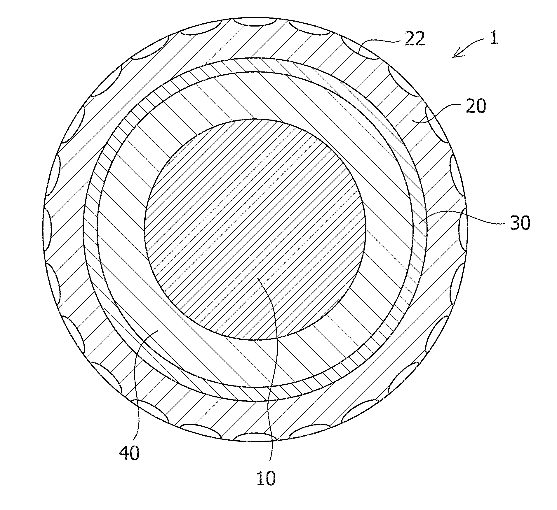
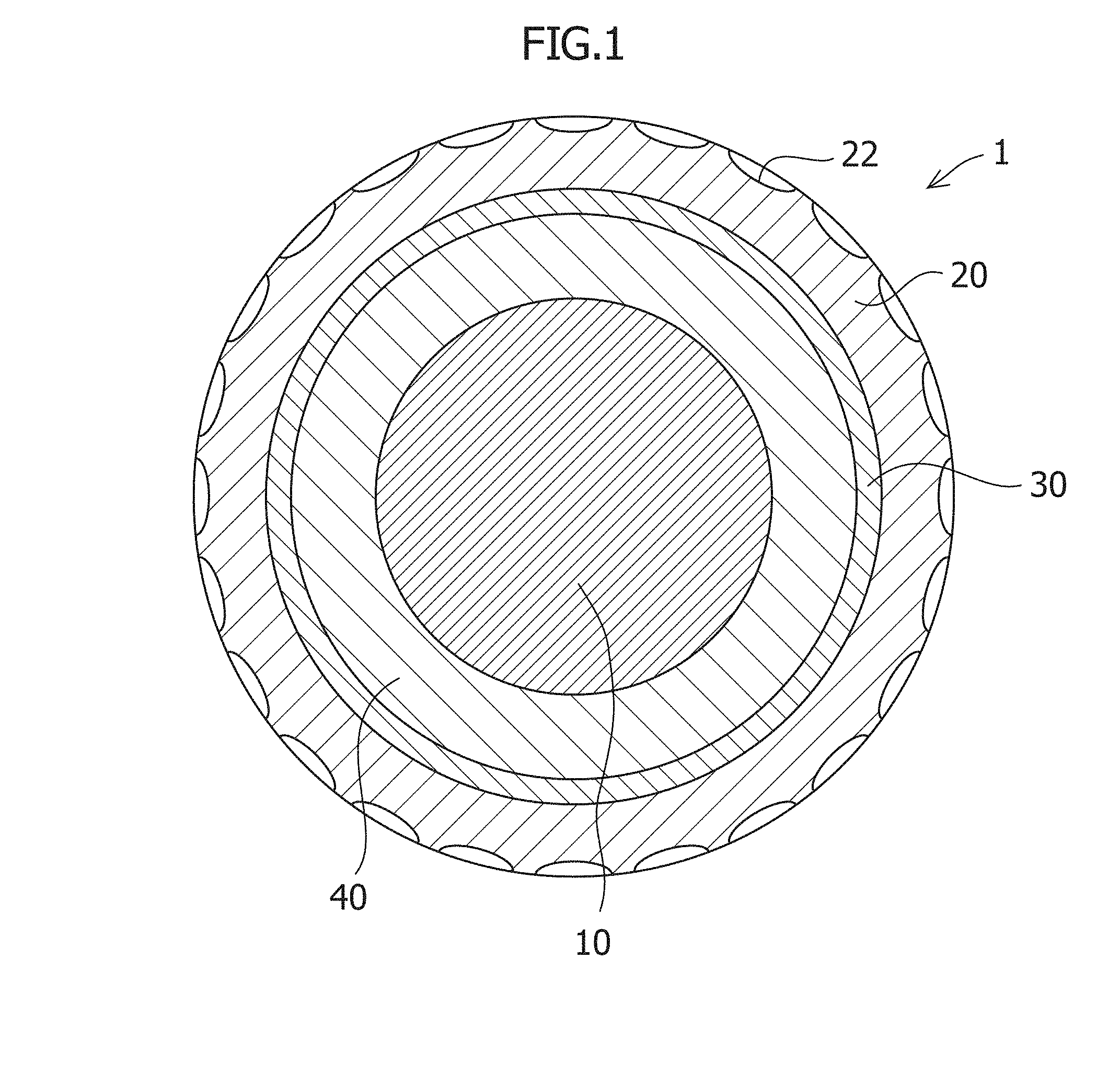
[0013] FIG. 1 is a cross-sectional view schematically illustrating an embodiment of the golf ball according to the present invention;
[0014] FIG. 2 is an enlarged diagram illustrating an example of the metal mesh layer used in the golf ball of FIG. 1; and
[0015] FIG. 3 is a photograph showing the state of covering the intermediate layer with the metal mesh layer in the preparation process of the golf ball according to the present invention.
DESCRIPTION OF PREFERRED EMBODIMENTS
[0016] Hereinafter, an embodiment of the golf ball according to the present invention is described with reference to the accompanying drawings.
[0017] As shown in FIG. 1, the golf ball 1 of the present embodiment mainly includes the core 10 located in the center of the ball, the cover 20 surrounding the outer circumference of the core 10, and the metal mesh layer 30 located between the core 10 and the cover 20. On the surface of the cover 20, a plurality of dimples 22 are formed. In addition, the golf ball 1 of the present embodiment includes the intermediate layer 40 between the core 10 and the metal mesh layer 30. It is to be noted that in the present embodiment, a golf ball having a three-piece structure composed of the core 10, the intermediate layer 40, and the cover 20 is described; however, the present invention is not limited to this, and a two-piece structure composed of the core 10 and the cover 20 may also be adopted, the intermediate layer 40 may adopt a structure having a plurality of layers further having a core-like function and/or a cover-like function, or the core 10 may have a structure having a plurality of layers.
[0018] The core 10 can be formed of a rubber composition containing a rubber as a main component. As the rubber (base material rubber) to be the main component, a wide variety of synthetic rubbers and natural rubbers can be used; the following rubbers can be used, without being limited to the following rubbers: polybutadiene rubber (BR), styrene-butadiene rubber (SBR), natural rubber (NR), polyisoprene rubber (IR), polyurethane rubber (PU), butyl rubber (IIR), vinyl polybutadiene rubber (VBR), ethylene-propylene rubber (EPDM), nitrile rubber (NBR), and silicone rubber. As the polybutadiene rubber (BR), for example, 1,2-polybutadiene and cis-1,4-polybutadiene can be used.
[0019] To the core 10, in addition to such base material rubbers, for example, a co-cross-linking material, a cross-linking initiator, a filler, an antiaging agent, an isomerization agent, a peptizer, sulfur, and an organosulfur compound can be optionally added. A resin may also be used as the main component, in place of a rubber; for example, a thermoplastic elastomer, an ionomer resin, and a mixture of these can also be used.
[0020] As the co-cross-linking material, without being limited to the following, for example, .alpha.,.beta.-unsaturated carboxylic acid or a metal salt thereof is preferably used. Examples of the .alpha.,.beta.-unsaturated carboxylic acid or a metal salt thereof include acrylic acid and methacrylic acid; and zinc salts, magnesium salts and calcium salts of these. The mixing amount of the co-cross-linking material is not limited to the following, but is preferably, for example, approximately 5 parts by weight or more, and more preferably approximately 10 parts by weight or more, in relation to 100 parts by weight of the base material rubber. In addition, the mixing amount of the co-cross-linking material is preferably approximately 70 parts by weight or less, and more preferably approximately 50 parts by weight or less.
[0021] As the cross-linking initiator, it is preferable to use an organic peroxide, and examples of the cross-linking initiator include, without being limited to, organic peroxides such as dicumyl peroxide, t-butyl peroxybenzoate, di-t-butyl peroxide, and 1,1-bis(t-butylperoxy)3,3,5-trimethylcyclohexane. The mixing amount of the cross-linking initiator is not limited to the following, but is preferably, for example, approximately 0.10 part by weight or more, more preferably approximately 0.15 part by weight or more, and further preferably approximately 0.30 part by weight or more, in relation to 100 parts by weight of the base material rubber. In addition, the mixing amount of the cross-linking initiator is preferably approximately 8 parts by weight or less, and more preferably approximately 6 parts by weight or less.
[0022] The filler is not limited to the following, but the following can be used as the filler: silver, gold, cobalt, chromium, copper, iron, germanium, manganese, molybdenum, nickel, lead, platinum, tin, titanium, tungsten, zinc, zirconium, barium sulfate, zinc oxide, manganese oxide, and the like. The filler is preferably in a powder form. The mixing amount of the filler is not limited to the following, but is preferably, for example, approximately 1 part by weight or more, more preferably approximately 2 parts by weight or more, and further preferably approximately 3 parts by weight or more, in relation to 100 parts by weight of the base material rubber. In addition, the mixing amount of the filler is preferably approximately 100 parts by weight or less, more preferably approximately 80 parts by weight or less, and further preferably approximately 70 parts by weight or less.
[0023] As the antiaging agent, without being limited to the following, for example, commercially available products such as Nocrac NS-6 (manufactured by Ouchi Shinko Chemical Industrial Co., Ltd.) can be used. The mixing amount of the antiaging agent is not limited to the following, but is preferably approximately 0.1 part by weight or more, and more preferably approximately 0.15 part by weight or more, in relation to 100 parts by weight of the base material rubber. In addition, the mixing amount of the antiaging agent is preferably approximately 1.0 part by weight or less, and more preferably approximately 0.7 part by weight or less.
[0024] The addition of an organic sulfur compound (peptizing material) allows the resilience of the core 30 to be improved. The organic sulfur compound is selected from thiophenols, thiocarboxylic acids and the metal salts thereof. Examples of the thiophenols and the thiocarboxylic acids include thiophenols such as pentachlorothiophenol, 4-t-butyl-o-thiophenol, 4-t-butylthiophenol, and 2-benzamidethiophenol; and thiocarboxylic acids such as thiobenzoic acid. In addition, as the metal salts of these, zinc salts and the like are preferable. The mixing amount of the organic sulfur compound is not limited to the following, but is preferably approximately 0.05 part by weight or more and more preferably approximately 0.1 part by weight or more. In addition, the mixing amount of the organic sulfur compound is preferably approximately 2 parts by weight or less, and more preferably approximately 1 part by weight or less.
[0025] The deflection hardness of the core 10 means the deformation magnitude (mm) of the core in the loading direction from a state in which the core is applied an initial load of 10 kgf (approximately 98 N) to a state in which the core is applied a final load of 130 kgf (approximately 1275 N). It means that the higher the deflection hardness of the core 10, the softer the core is. The deflection hardness of the core 10 is preferably within a range from 2.5 to 4.5, and further preferably within a range from 3.0 to 4.0.
[0026] The core 10 substantially has a spherical shape. The upper limit of the outer diameter of the core 10 is preferably 42 mm or less, more preferably 41 mm or less, and further preferably 40 mm or less. The lower limit of the outer diameter of the core 10 is preferably 5 mm or more, more preferably 15 mm or more, and most preferably 25 mm or more. As the core 10, FIG. 1 shows a solid core, but the core 10 is not limited to this, but may also be a hollow core. In addition, in FIG. 1, the core 10 is shown to have a single layer, but the core 10 is not limited to this and may be a core composed of a plurality of layers such as a center core and a layer surrounding the core.
[0027] As the method for molding the core 10, it is possible to adopt a heretofore known method for molding a core of a golf ball. For example, a core can be obtained by kneading a material containing a base material rubber with a kneading machine, and by pressure vulcanization molding of the resulting kneaded product with a spherical mold, although the method for obtaining a core is not limited to this. As a method for molding a core having a plurality of layers, it is possible to adopt a heretofore known method for molding a solid core having a multilayer structure. For example, a multilayer core can be obtained as follows: a center core is obtained by kneading materials with a kneading machine, and by pressure vulcanization molding of the resulting kneaded product with a spherical mold; then materials for a surrounding layer are kneaded with a kneading machine, and the resulting kneaded product is molded into a sheet shape to obtain a sheet for the surrounding layer; the center core is covered with the sheet to prepare a covered center core; then, the covered center core is subjected to a pressure vulcanization molding to prepare a multilayer core.
[0028] As shown in FIG. 2, the metal mesh layer 30 is a layer constituted with metal wires 32 arranged in a network, having a mesh structure with a plurality of longitudinal wires 32a and the transverse wires 32b being at right angles to each other. A mesh structure is represented, as a common specification, with the wire diameter d of the metal wire 32 and the mesh count M, the number of the mesh per 1 inch (25.4 mm). In the metal mesh layer 30, the wire diameter d is within a range from 0.01 to 0.5 mm, and the mesh count M is within a range from 16 to 1000. By setting the wire diameter d and the mesh count M within these ranges respectively, the elastic force in the flexural direction and the rigidity in the tensile direction required for the golf ball 1 can be given. The wire diameter is within a range preferably from 0.02 to 0.40 mm, and more preferably from 0.04 to 0.20 mm. The mesh count is within a range preferably from 20 to 250, and more preferably from 50 to 200.
[0029] In addition, when the wire diameter is represented by d and the mesh count is represented by M, the metal mesh layer 30 preferably has a value of d.times.M falling within a range from 5 to 12. By setting the value of d.times.M so as to be 5 or more, it is possible to sufficiently impart to the golf ball 1 a required rigidity in the tensile direction. In addition, by setting the value of d.times.M so as to be 12 or less, it is possible to sufficiently impart to the golf ball 1 a required elasticity in the flex direction. The value of d.times.M is more preferably within a range from 8 to 12.
[0030] In addition, the opening A, that is, the distance between the metal wires 32, can be represented by the following formula when the wire diameter is represented by d and the mesh count is represented by M. The opening A is within a range preferably from 0.05 to 1.10 mm, more preferably from 0.07 to 0.60 mm, and further preferably from 0.10 to 0.20 mm.
A = 25.4 M - d ##EQU00001##
[0031] As the metal material of the metal wire 32, stainless steel, steel, nickel alloys, aluminum, aluminum alloys, copper, copper alloys and the like can be used; among these, stainless steel is particularly preferable because of its rust resistant property.
[0032] An example of the method for forming the metal mesh layer 30 on the surface of the core 10 or the intermediate layer is as follows: two pieces of metal mesh materials each having a planar calabash shape are prepared, the two pieces of the metal mesh materials are assembled in such a way that around the constricted portion of one of the two pieces of metal mesh materials, both end portions of the other metal mesh material are connected, and thus, a spherical metal mesh layer 30 can be formed. The metal mesh materials are preferably pressured and bonded while being heated to the surface of the core 10 or the intermediate layer.
[0033] The materials for forming the cover 20 are not limited to the following, but the cover 20 can be formed by using the following: thermoplastic polyurethane, ionomer resins, or the mixtures of these. In addition, in the cover 20, in addition to the abovementioned main component, other thermoplastic elastomers, polyisocyanate compounds, fatty acids or derivatives thereof, basic inorganic metal compounds, fillers and the like can be added.
[0034] The structure of the thermoplastic polyurethane material is composed of a soft segment composed of a polymer polyol (polymeric glycol) and a chain extender and polyisocyanate constituting the hard segment. Here, the polymer polyol to be a raw material is not particularly limited, but is preferably, in the present invention, a polyester-based polyol and a polyether-based polyol. Specific examples of the polyester-based polyol include: adipate-based polyols such as polyethylene adipate glycol, polypropylene adipate glycol, polybutadiene adipate glycol, and polyhexamethylene adipate glycol; and lactone-based polyols such as polycaprolactone polyol. Examples of the polyether polyol include poly(ethylene glycol), poly(propylene glycol), and poly(tetramethylene glycol).
[0035] The chain extender is not particularly limited; in the present invention, it is possible to use as a chain extender a low molecular weight compound having two or more active hydrogen atoms that can react with isocyanate groups in the molecule thereof, and having a molecular weight of 2,000 or less; in particular, an aliphatic diol having 2 to 12 carbon atoms is preferable. Specific examples of the chain extender may include 1,4-butylene glycol, 1,2-ethylene glycol, 1,3-butanediol, 1,6-hexanediol, and 2,2-dimethyl-1,3-propanediol; in particular, 1,4-butylene glycol is preferable.
[0036] The polyisocyanate compound is not particularly limited, but in the present invention, for example, it is possible to use one or two or more selected from the group consisting of 4,4'-diphenylmethane diisocyanate, 2,4-toluene diisocyanate, 2,6-toluene diisocyanate, p-phenylene diisocyanate, xylylene diisocyanate, naphthylene 1,5-diisocyanate, tetramethylxylene diisocyanate, hydrogenated xylylene diisocyanate, dicyclohexylmethane diisocyanate, tetramethylene diisocyanate, hexamethylene diisocyanate, isophorone diisocyanate, norbornene diisocyanate, trimethylhexamethylene diisocyanate, and dimeric acid diisocyanate. However, some isocyanate species make it difficult to control the cross-linking reaction during injection molding, and accordingly, in the present invention, 4,4'-diphenylmethane diisocyanate, an aromatic diisocyanate, is preferable from the viewpoint of the balance between the stability during production and the developed physical properties.
[0037] As the ionomer resin, it is possible to use a resin containing, as the base resin(s), the following (a) component and/or the following (b) component, but the ionomer resin is not limited to this. In addition, to the one or more base resins, the following (c) component can be optionally added. The (a) component is a ternary random olefin-unsaturated carboxylic acid-unsaturated carboxylic acid ester copolymer and/or a metal salt thereof, the (b) component is an olefin-unsaturated carboxylic acid binary random copolymer and/or a metal salt thereof, and the (c) component is a thermoplastic block copolymer having a crystalline polyolefin block, and polyethylene/butylene random copolymer.
[0038] In addition, in the cover 20, in addition to the main component of the above-mentioned thermoplastic polyurethane or ionomer resin, thermoplastic resins or elastomers other than the thermoplastic polyurethane can be mixed. Specifically, it is possible to use one or two or more of such thermoplastic resins or elastomers selected from polyester elastomer, polyamide elastomer, ionomer resin, styrene block elastomer, hydrogenated styrene butadiene rubber, styrene-ethylene/butylene-ethylene block copolymer or the modified products thereof, ethylene-ethylene/butylene-ethylene block copolymer or the modified product thereof, styrene-ethylene/butylene-styrene block copolymer or the modified product thereof, ABS resin, polyacetal, polyethylene and nylon resin. In particular, for example, because the resilience and the abrasion resistance are improved due to the reaction with the isocyanate group while the productivity is being satisfactorily maintained, it is suitable to adopt polyester elastomer, polyamide elastomer and polyacetal. When the abovementioned components are mixed, the mixing amounts thereof are appropriately selected, without being particularly limited, according to the regulation of the hardness, improvement of the resilience, the improvement of the fluidity, the improvement of the adhesiveness and the like of the cover material; however, the mixing amount(s) of the above-mentioned component(s) can be set preferably to be 5 parts by weight or more in relation to 100 parts by weight of the thermoplastic polyurethane component. In addition, the upper limit of the mixing amount(s) is also not particularly limited, but can be set to be preferably 100 parts by weight or less, more preferably 75 parts by weight or less, and further preferably 50 parts by weight or less, in relation to 100 parts by weight of the thermoplastic polyurethane component. In addition, polyisocyanate compounds, fatty acids or derivatives thereof, basic inorganic metal compounds, fillers and the like can also be added.
[0039] The hardness of the cover 20 is preferably 56 or less in terms of the Shore D hardness, for the purpose of securing the approach spin and exhibiting the effect of the metal mesh. The upper limit of the hardness of the cover 20 is more preferably 53 or less, and further preferably 48 or less. The lower limit of the hardness of the cover 20 is preferably 30 or more and more preferably 40 or more, in terms of the Shore D hardness.
[0040] The lower limit of the thickness of the cover 20 is preferably 0.2 mm or more and more preferably 0.4 mm or more, without being limited to these values. In addition, the upper limit of the thickness of the cover 20 is preferably 4 mm or less, more preferably 3 mm or less, and further preferably 2 mm or less. On the surface of the cover 20, a plurality of dimples 22 are formed. The size, shape and number of the dimples can be appropriately designed according to the desired aerodynamic properties of the golf ball 1.
[0041] As the method for forming the cover 20, a heretofore known method for forming a cover of a golf ball can be adopted. For example, the cover 20 is formed by injection molding the material for the cover in a mold, without being particularly limited to this. The mold for forming the cover has a cavity for molding the cover, and has a plurality of projections for forming the dimples on the wall surface of the cavity. By arranging the core 10 in the center of the cavity, the cover 20 is formed so as to cover the core 10.
[0042] The intermediate layer 40 can be formed by using, as the material for the intermediate layer 40, the same materials as the abovementioned materials for the cover 20, namely, thermoplastic polyurethane, an ionomer resin, or a mixture of these. In addition, in the intermediate layer 40, in addition to the abovementioned main component, other thermoplastic elastomers, polyisocyanate compounds, fatty acids or the derivatives thereof, basic inorganic metal compounds, fillers and the like can be added.
[0043] The lower limit of the material hardness of the intermediate layer 40 is preferably 50 or more, and further preferably 55 or more, in terms of the Shore D hardness, without being limited to these values. In addition, the upper limit of the hardness of the intermediate layer 40 is preferably 70 or less, and further preferably 65 or less, in terms of the Shore D hardness.
[0044] The thickness of the intermediate layer 40 is preferably 0.5 mm or more, and more preferably 1 mm or more, without being limited to these values. In addition, the thickness of the intermediate layer 40 is preferably 10 mm or less, more preferably 5 mm or less, and further preferably 3 mm or less.
[0045] The golf ball 1 obtained by the abovementioned constitution preferably has a .mu., hardness of 2.0 mm or more. The .mu., hardness of a golf ball means the compression deformation magnitude (deflection magnitude) when a load is applied to the golf ball from an initial load of 98 N (10 kgf) to a load of 1275 N (130 kgf). The unit of the .mu., hardness is given in mm. When an object has a low numerical value of the .mu., hardness, the object is hard, and when an object has a high numerical value of the .mu., hardness, the object is soft. The lower limit of the .mu., hardness is more preferably 1.5 mm or more, and further preferably 2.3 mm or more. In addition, the upper limit of the .mu., hardness is preferably 5.0 mm or less, more preferably 4.0 mm or less, and further preferably 3.2 mm or less.
EXAMPLES
[0046] The golf balls of Examples and Comparative Examples having the constitutions shown in Table 1 were prepared, and the tests for measuring the performances of the prepared golf balls were performed. The compositions of the materials of the cores shown in Table 1 are shown in Table 2, and the compositions of the materials of the intermediate layers and the covers are shown in Table 3. It is to be noted that the mixing amounts of the individual components in Table 2 and Table 3 are represented in terms of parts by weight. The metal mesh layers of Examples were all made of the same metal, stainless steel. In addition, in all of Examples and Comparative Examples, the covers having the same dimple arrangement were formed. In addition, each of the golf balls was prepared by regulating the core composition in such a way that the deflection hardness was 2.5 mm, the outer diameter was 42.7 mm, the weight was 45.4 g, and the USGA initial velocity was 77 m/s.
TABLE-US-00001 TABLE 1 Examples Comparative Examples 1 2 3 4 1 2 3 4 Core Material a b c d e b c f Diameter 38.2 38.2 38.2 41.1 38.2 38.2 38.2 38.2 (mm) Intermediate Material B B B -- B B B C layer Shore D 62 62 62 -- 62 62 62 68 hardness Outer 41.1 41.1 41.1 -- 41.1 41.1 41.1 41.1 diameter (mm) Thickness 1.45 1.45 1.45 -- 1.45 1.45 1.45 1.45 (mm) Metal Mesh count M 100 250 20 100 -- 500 10 -- mesh Wire 0.1 0.04 0.25 0.1 -- 0.025 0.45 -- layer diameter (mm) d .times. M 10 10 5 10 -- 12.5 4.5 -- Cover Material A A A A A A A A Shore D 47 47 47 47 47 47 47 47 hardness Thickness 0.8 0.8 0.8 0.8 0.8 0.8 0.8 0.8 (mm) Spin rate (rpm) 2530 2620 2680 2610 2850 2860 3020 2640 Durability Superior Superior Good Superior Superior Superior Good Inferior
TABLE-US-00002 TABLE 2 A b c d e f Polybutadiene 100 100 100 100 100 100 Peroxide (1) 0.6 0.6 0.6 0.6 0.6 0.6 Peroxide (2) 0.6 0.6 0.6 0.6 0.6 0.6 Zinc oxide 10.0 15.0 9.5 4.0 20.0 21.0 Tungsten 0 0 0 0 0 0 Antiaging agent 0.1 0.1 0.1 0.1 0.1 0.1 Zinc acrylate 28.5 29.1 28.0 33.0 27.5 25.5 Pentachlorothiophenol zinc 1.0 1.0 1.0 1.0 0.1 0.1 salt
[0047] The following were used for the respective components in Table 2 showing the compositions of the core materials.
[0048] The peroxide (1) was Percumyl D (trade name), dicumyl peroxide, manufactured by NOF Corp.
[0049] The peroxide (2) was Perhexa C-40 (trade name), a mixture of 1,1-di(t-butylperoxy)cyclohexane and silica, manufactured by NOF Corp.
[0050] The antiaging agent was Nocrac NS-6 (trade name), 2,2'-methylenebis(4-methyl-6-tert-butylphenol), manufactured by Ouchi Shinko Chemical Industrial Co., Ltd.
TABLE-US-00003 TABLE 3 A B C Surlyn S8150 -- -- 100 Himilan 1706 -- 35 -- Himilan 1557 -- 15 -- Himilan 1605 -- 50 -- Himilan 1601 -- -- -- T-8290 75 -- -- T-8283 25 -- -- Hytrel 4001 11 -- -- Polyethylene wax 1.2 -- -- Isocyanate compound 7.5 -- -- Titanium oxide 3.9 -- -- Trimethylol propane (TMP) -- 1.1 --
[0051] The following were used for the respective components in Table 3 showing the compositions of the materials of the cover and the intermediate layer.
[0052] Surlyn S8150 is an ionomer resin manufactured by Du Pont Corp.
[0053] Himilan 1706, Himilan 1557, Himilan 1605, and Himilan 1601 are ionomer resins of binary copolymers manufactured by Du Pont-Mitsui Polychemicals Co., Ltd.
[0054] T-8290 and T-8283 are MDI-PTMG type thermoplastic polyurethanes manufactured by DIC Bayer Polymer Ltd.; trademark: Pandex.
[0055] Hytrel 4001 is a thermoplastic polyether ester elastomer manufactured by Du Pont-Toray Co., Ltd.
[0056] The polyethylene wax is Sanwax 161P (trade name) manufactured by Sanyo Chemical Industries, Ltd.
[0057] The isocyanate compound is 4,4'-diphenylmethane diisocyanate.
[0058] Titanium oxide is Tipaque R-550 (trade name) manufactured by Ishihara Sangyo Kaisha, Ltd.
[0059] Trimethylol propane is a low molecular weight polyol manufactured by Toyo Chemicals Co., Ltd.
[0060] The USGA initial velocity is a value measured by using a USGA drum rotation type initial velocity meter and a same type initial velocity measurement device, authorized by R&A. A golf ball was temperature regulated in an environment at 23.9.+-.1.degree. C. for 3 hours or more, and then tested in a room at room temperature, 23.+-.2.degree. C. By using a head of 250 pounds (113.4 kg), each of sample balls was hit at a hitting speed of 143.8 ft/s (43.83 m/s); specifically, 30 balls of each of the samples were each twice hit, the times passing through 6.28 ft (1.91 m) were measured, and thus, the initial velocity (m/s) was calculated.
[0061] The spin rates shown in Table 1 are the spin rates (rpm) obtained by photographing golf balls, by using a high speed camera, immediately after the hitting of the golf balls when a driver (W#1) was mounted in a swing robot (manufactured by Miyamae Co., Ltd.) and the balls were hit. The driver used was the TourStage X-Drive Type 455 9.5.degree., and the hitting was performed with a head speed of 45 m/s.
[0062] The durabilities in Table 1 are the durabilities of the golf balls evaluated by using the ADC Ball COR Durability Tester manufactured by Automated Design Corporation, in United States. This testing machine has a function to allow a golf ball to continuously collide with two sheets of metal plates arranged in parallel with each other after the golf ball has been discharged with an air pressure. The incident velocity to the metal plate was set to be 43 m/s. Thus, the average value of the numbers of the discharges required for breaking the golf balls was determined. The average value was obtained by averaging the numbers of the discharges required for breaking the golf balls when ten golf balls were prepared for each of the samples, and the golf balls were discharged. The evaluations are as follows: the case where the average value is 200 or more is marked with "Superior"; the case where the average value is 100 or more and less than 200 is marked with "Good"; and the case where the average value is less than 100 is marked with "Inferior".
[0063] As shown in Table 1, Examples 1 to 3 each providing inside the cover a metal mesh layer having a predetermined wire diameter and a predetermined mesh count was able to drastically decrease the spin rate in the driver shot, as compared with Comparative Example 1 without such a metal mesh layer. In addition, the durabilities of the golf balls of Examples 1 to 3 were excellent and comparable with the durability of the golf ball of Comparative Example 1. On the other hand, compared with Comparative Example 1, Comparative Example 4 in which the material for the intermediate layer was altered to increase the hardness of the intermediate layer was able to drastically decrease the spin rate in the driver shot due to such an intermediate layer, but resulted in a durability that was unable to withstand practical use.
[0064] Example 4 in which no intermediate layer was provided, and a metal mesh layer having a predetermined wire diameter and a predetermined mush count was provided between the core and the cover was able to drastically decrease the spin rate in the driver shot, in the same manner as in Examples 1 to 3. The durability was also free from problems. On the other hand, with a structure in which a solid metal layer is provided in place of the metal mesh layer, a golf ball was not able to be prepared with a predetermined .mu. hardness, and the .mu. hardness was not able to be measured because the golf ball was deformed due to hitting. Comparative Examples 2 and 3 in which the wire diameters and the mesh counts of the metal mesh layers were not within the predetermined ranges were also not able to drastically decrease the spin rates in the driver shot.
* * * * *
uspto.report is an independent third-party trademark research tool that is not affiliated, endorsed, or sponsored by the United States Patent and Trademark Office (USPTO) or any other governmental organization. The information provided by uspto.report is based on publicly available data at the time of writing and is intended for informational purposes only.
While we strive to provide accurate and up-to-date information, we do not guarantee the accuracy, completeness, reliability, or suitability of the information displayed on this site. The use of this site is at your own risk. Any reliance you place on such information is therefore strictly at your own risk.
All official trademark data, including owner information, should be verified by visiting the official USPTO website at www.uspto.gov. This site is not intended to replace professional legal advice and should not be used as a substitute for consulting with a legal professional who is knowledgeable about trademark law.